US7963085B2 - Multifunctional periodic cellular solids and the method of making same - Google Patents
Multifunctional periodic cellular solids and the method of making same Download PDFInfo
- Publication number
- US7963085B2 US7963085B2 US10/479,833 US47983303A US7963085B2 US 7963085 B2 US7963085 B2 US 7963085B2 US 47983303 A US47983303 A US 47983303A US 7963085 B2 US7963085 B2 US 7963085B2
- Authority
- US
- United States
- Prior art keywords
- dimensional space
- space filling
- truss
- sheet
- filling layers
- Prior art date
- Legal status (The legal status is an assumption and is not a legal conclusion. Google has not performed a legal analysis and makes no representation as to the accuracy of the status listed.)
- Active, expires
Links
Images


Classifications
-
- B—PERFORMING OPERATIONS; TRANSPORTING
- B29—WORKING OF PLASTICS; WORKING OF SUBSTANCES IN A PLASTIC STATE IN GENERAL
- B29D—PRODUCING PARTICULAR ARTICLES FROM PLASTICS OR FROM SUBSTANCES IN A PLASTIC STATE
- B29D24/00—Producing articles with hollow walls
-
- E—FIXED CONSTRUCTIONS
- E04—BUILDING
- E04C—STRUCTURAL ELEMENTS; BUILDING MATERIALS
- E04C2/00—Building elements of relatively thin form for the construction of parts of buildings, e.g. sheet materials, slabs, or panels
- E04C2/30—Building elements of relatively thin form for the construction of parts of buildings, e.g. sheet materials, slabs, or panels characterised by the shape or structure
- E04C2/34—Building elements of relatively thin form for the construction of parts of buildings, e.g. sheet materials, slabs, or panels characterised by the shape or structure composed of two or more spaced sheet-like parts
- E04C2/3405—Building elements of relatively thin form for the construction of parts of buildings, e.g. sheet materials, slabs, or panels characterised by the shape or structure composed of two or more spaced sheet-like parts spaced apart by profiled spacer sheets
- E04C2002/3411—Dimpled spacer sheets
- E04C2002/3422—Dimpled spacer sheets with polygonal dimples
-
- E—FIXED CONSTRUCTIONS
- E04—BUILDING
- E04C—STRUCTURAL ELEMENTS; BUILDING MATERIALS
- E04C2/00—Building elements of relatively thin form for the construction of parts of buildings, e.g. sheet materials, slabs, or panels
- E04C2/30—Building elements of relatively thin form for the construction of parts of buildings, e.g. sheet materials, slabs, or panels characterised by the shape or structure
- E04C2/34—Building elements of relatively thin form for the construction of parts of buildings, e.g. sheet materials, slabs, or panels characterised by the shape or structure composed of two or more spaced sheet-like parts
- E04C2002/3488—Building elements of relatively thin form for the construction of parts of buildings, e.g. sheet materials, slabs, or panels characterised by the shape or structure composed of two or more spaced sheet-like parts spaced apart by frame like structures
-
- Y—GENERAL TAGGING OF NEW TECHNOLOGICAL DEVELOPMENTS; GENERAL TAGGING OF CROSS-SECTIONAL TECHNOLOGIES SPANNING OVER SEVERAL SECTIONS OF THE IPC; TECHNICAL SUBJECTS COVERED BY FORMER USPC CROSS-REFERENCE ART COLLECTIONS [XRACs] AND DIGESTS
- Y10—TECHNICAL SUBJECTS COVERED BY FORMER USPC
- Y10T—TECHNICAL SUBJECTS COVERED BY FORMER US CLASSIFICATION
- Y10T428/00—Stock material or miscellaneous articles
- Y10T428/24—Structurally defined web or sheet [e.g., overall dimension, etc.]
- Y10T428/24174—Structurally defined web or sheet [e.g., overall dimension, etc.] including sheet or component perpendicular to plane of web or sheet
-
- Y—GENERAL TAGGING OF NEW TECHNOLOGICAL DEVELOPMENTS; GENERAL TAGGING OF CROSS-SECTIONAL TECHNOLOGIES SPANNING OVER SEVERAL SECTIONS OF THE IPC; TECHNICAL SUBJECTS COVERED BY FORMER USPC CROSS-REFERENCE ART COLLECTIONS [XRACs] AND DIGESTS
- Y10—TECHNICAL SUBJECTS COVERED BY FORMER USPC
- Y10T—TECHNICAL SUBJECTS COVERED BY FORMER US CLASSIFICATION
- Y10T428/00—Stock material or miscellaneous articles
- Y10T428/24—Structurally defined web or sheet [e.g., overall dimension, etc.]
- Y10T428/24273—Structurally defined web or sheet [e.g., overall dimension, etc.] including aperture
- Y10T428/24298—Noncircular aperture [e.g., slit, diamond, rectangular, etc.]
- Y10T428/24314—Slit or elongated
Definitions
- the present invention relates generally to improved structural/multifunctional material designs and methods for their manufacture. More particularly, the invention is directed to the use of trusses, plates, strips, sheets and bonding techniques to form periodic cellular solids.
- the properties of a cellular solid are sensitive to both the topology of the cell material and its properties.
- the main obstacle to obtaining superior properties has involved gaining good control over the distribution of material at the cell level in a cost effective way.
- the most common and least expensive synthetic cellular solids remain stochastic in nature; made by variants of foaming in the liquid, solid or semi-solid state [1].
- Other methods involve the solidification of liquids containing dissolved gases, bonding of hollow spheres, vapor deposition onto sacrificial templates, or investment casting using a stochastic cellular structure mold. These types of manufacturing approaches lead to cellular architectures with open, closed or mixed types of porosity.
- Open cell stochastic foams are used for sound attenuation and impact energy absorption.
- Open cell stochastic foams can be made using reticulated polymer foam templates. In one approach, the template is used as the pattern for an investment casting mold which is then filled with a liquid (e.g. molten metal) and solidified. In others, a vapor or fine powder slurry is deposited directly on to the template. In the latter, a subsequent heat treatment removes the organic compounds and densifies the structure.
- Open cell stochastic metal foams are used for lightweight heat exchangers and as the electrodes in nickel metal hydride batteries.
- trusses Small polymeric, ceramic and metallic trusses of this type are currently manufactured using rapid proto-typing or injection molding techniques. For example, by fabricating a polymer or wax pattern of the appropriate truss architecture, miniature metal trusses follow by investment casting. The resulting structures are known as lattice block or truss materials. Individual cells can be small (a few mm). By manipulating the truss architecture, properties can be widely modified.
- both stochastic and periodic cellular metals have attracted interest as alternatives to honeycomb when used as the cores of sandwich structures designed to support in-plane compressive or bending loads [1].
- these cellular metal based approaches must compete against established panel stiffening and strengthening concepts.
- Conventional panel stiffening involves the attachment of stringers that increase the polar and second moment of cross-section area with modest added weight [1].
- Panels of this type are often made by machining stiffeners from thick blanks and fastening to a sheet. When fabricated in this way, the panels can be quite light and stiff however, they also show substantial anisotropy in the bending plane and are relatively expensive due to the poor utilization of material and high machining cost.
- waffling or sandwich construction [1-4].
- thin strong skins are bonded to the sides of a lightweight core 3 as shown in FIG. 1 .
- the skins 4 provide support in bending with one skin in compression and the other in tension.
- the core functions in a manner similar to the web of an I-beam. That is, it resists shear and compressive loads while separating the skins far apart to generate a high second moment cross-section area and therefore high rigidity.
- Honeycomb core sandwich structures 2 are the current state-of-the-art choice for weight sensitive applications such as aircraft and satellite structures [2]. But there are difficulties with forming them into complex (non-planar) shapes due to induced anticlastic curvature [2]. Also, the closed nature of the porosity can trap moisture leading to corrosion. In space applications, their skins are susceptible to interfacial debonding.
- Open cell cores based upon tetrahedral truss concepts [5,6] allow fluids to readily pass through which could make them less susceptible to internal corrosion and depressurization induced delamination. When used as sandwich cores, they are more amenable to shaping into complex shapes. They are also attractive for multifunctional applications such as cross flow heat exchangers due to the interconnected nature of the porosity [1].
- FIG. 2 is a graphical representation that summarizes the Young's and shear moduli relative density relationships for various cellular concepts.
- the present invention truss-based cellular solids provides a host of new and interesting multifunctional structures that could be made.
- the present invention provides cost effective ways of making high quality truss-based cellular solids of this type that overcomes many obstacles of the prior art.
- the present inventors have recently suggested a textile-based approach—as shown in pending co-assigned PCT International Application No.
- PCT/US01/17363 entitled “Multifunctional Periodic Cellular Solids And The Method Of Making Thereof,” filed on May 29, 2001, of which is hereby incorporated by reference herein—and now provide with the present invention another way that includes closed and mixed types of porosity along with the open type.
- Metals, ceramics, glasses, polymers, composites and even semiconductors can all be fabricated by the present invention method.
- metals there is provided a perforation and deformation process followed by transient liquid phase bonding.
- miniature truss-like structures with exceptional strength/weight ratios for multifunctional structural applications are readily made at acceptable cost.
- the cores of these structures are bonded to thin metal facesheets using the transient liquid phase approach.
- These structures can be planar or curved and can be bonded to themselves, facesheets or other structures using the transient liquid phase or other bonding approaches.
- the present invention provides methods of making truss-based periodic cellular solids that have improved structural properties and multifunctional design.
- the present invention provides many materials (metals, ceramics, glasses, polymers, composites and even semiconductors) that can be shaped into cellular, truss-like architectures with open, closed or mixed types of porosity and then very uniformly arranged in controlled, three-dimensional space-filling arrays.
- the truss-like elements do not necessarily have a constant cross-section, nor are they necessarily straight or solid throughout (they could be hollow). Their cross sections can be circular, square, triangular, I-beam or other shapes of interest depending on multifunctional needs.
- the present invention provides a truss structure comprising:
- the present invention provides a method of making a truss structure comprising:
- the present invention provides a plate or strip structure comprising:
- the present invention provides a method of making a truss structure comprising:
- one or more embodiments provide a method for punching or stamping the truss sheets or the like that shapes the sheet and punches the hole(s) during the same operation (e.g., CNC machines) at ambient or elevated temperature conditions.
- one or more embodiments provide a method for fabricating truss sheets.
- the method includes bending and punching operations that can be combined by using appropriately shaped dies and CNC machines, wherein the processes can be performed either under ambient or hot temperature conditions, and in the latter, superplastic conditions can be utilized.
- FIG. 1 is a schematic perspective view of a honeycomb core sandwich structure.
- FIG. 2 is a graphical representation that summarizes the Young's and shear moduli relative density relationships for various cellular concepts.
- FIG. 3 shows a schematic representation of triad or truss unit 120 of the present invention.
- FIG. 4 is a graphical representation of the material dependent relative density relationships for minimum mass tetrahedral truss cores.
- FIG. 5 illustrates a press apparatus used for deforming the shape of truss cores.
- FIG. 6(A) photographically depicts the tetrahedral truss core after shaping.
- FIG. 6(B) photographically depicts enlarged view of the a preferred core/facesheet bond.
- FIG. 7 is the graphical representation of the measured load-deflection data obtained during the beam-flexure test.
- FIGS. 9 (A)-(B) are graphical representations demonstrating relative property comparisons for honeycomb and tetrahedral truss core systems for shear modulus and shear strength, respectively.
- FIGS. 10(A)-10(B) show a schematic representation of a hollow cubic or rectangular shaped structure 271 in a partially constructed status and a fully constructed status, respectively.
- FIGS. 11(A) and 12(A) are schematic representations of a second aspect of the present invention wherein prior to shaping there is shown a sheet 401 containing hexagonal perforations 402 and a sheet 403 containing square perforations 404 , respectively.
- FIGS. 11(B) and 12(B) are schematic representations of truss structures 405 , 406 , formed from the hexagonal perforated 401 and square perforated sheets 403 , respectively.
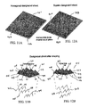
- FIGS. 13(A) and 14(A) are schematic representations of a third aspect of the present invention, wherein prior to shaping there is shown a sheet 501 containing hexagonal apertures 502 and a sheet 503 containing square apertures 504 .
- the cell shapes can be varied using an appropriately shaped tool.
- FIGS. 13(B) and 4(B) are schematic representations of truss structures 505 , 506 , formed from the hexagonal perforated 501 and square perforated sheets 503 , respectively.
- FIGS. 15(A) and 15(B) are schematic representations of a rolling system and a stamping system, respectively.
- a layer-oriented solid face sheet 701 having an inner surface 702 and an outer surface 703 can be bonded to the three-dimensional space layer 710 (i.e. core).
- FIG. 16(B) there is shown a layer-oriented solid face sheet 706 that is bonded to the three-dimensional space layer 710 (i.e. core) wherein the face sheet 706 is a sheet having triangular shaped apertures therein.
- FIG. 17(A) illustrate the sheets 715 , 716 , 717 having spot bonds 718 prior to expansion.
- FIG. 17(B) illustrate the structure 719 after sheet has been-expanded and bonded to the face sheets 715 , 717
- FIGS. 18 (A)-(F) schematically show various methods of bonding of metal trusses to solid or porous facesheets.
- FIGS. 19(A) and 19 (B) shows a photographic depiction of an the apparatus 720 for an exemplary process to be used to fabricate sheets 720 of miniature wrought metal trusses from a perforated metal sheet.
- FIGS. 20 (A)-(D) are photographic depictions of the resultant three dimensional layer 722 , showing the side view, first perspective view, second perspective view, respectively.
- FIG. 21 is photographic depiction of the resultant miniature tetragonal truss 722 having individual tetrahedral truss units.
- FIGS. 22 (A)-(C) show exemplary truss units 731 , 732 , 733 that are tetrahedral, pyramidal, and kagome shaped, respectively.
- FIG. 23(A) schematically show a side view of the truss structure illustrating that, three-dimensional arrays, truss units, or sandwich structures 741 may be curved, bent, or shaped.
- FIG. 23(B) schematically show a perspective view of a hollow cubic or rectangular structures 742 illustrating that it may be curved, bent, or shaped.
- FIG. 24 is photographic depiction of a tetrahedral truss core 751 with facesheets 752 containing hexagonal holes 753 .
- the present invention provides constructed cellular solids structures—and method of manufacturing the same—for multifunctional applications (e.g., mechanical impact/blast absorption, thermal management capacity, noise attenuation, catalytic activity, filtration efficiency, electrical energy storage, retardation of chemical reactions and/or fire or act as a host for the in-growth of biological tissue, etc.) in addition to load support.
- multifunctional applications e.g., mechanical impact/blast absorption, thermal management capacity, noise attenuation, catalytic activity, filtration efficiency, electrical energy storage, retardation of chemical reactions and/or fire or act as a host for the in-growth of biological tissue, etc.
- An example of electrical energy storage technology is provided in co-assigned PCT International Application No. PCT/US01/25158, entitled “Multifunctional Battery and Method of Making the Same,” filed Aug. 10, 2001, of which is hereby incorporated by reference herein in its entirety.
- thermal management technology is provided in co-assigned PCT International Application No. PCT/US01/22266, entitled “He
- the performance of the present invention cellular solid as a thermal management system, a catalyst support, a current collector, a noise damping system, a fire retarding structure. etc. depends on the topology of the porosity.
- the present invention cellular solid may be interconnected (as intrusses) or closed (as in many foams or honeycomb in the form of sandwich panels).
- the present invention provides porosity in the form of open, closed and combinations of these mixed together, as well as intermixing multiple materials to create these structures.
- the invention provides optimally designed cellular solids with multifunctional possibilities.
- the present invention provides small elements of a chosen material that can be very uniformly arranged in controlled, three-dimensional space-filling arrays.
- the ligaments defining the cell walls do not necessarily have a constant cross section, nor need they be solid throughout or straight.
- a cellular structure of highly repeatable cell geometry and few imperfections is the result.
- the bonds hold the elements together in a desired configuration and allow load to be efficiently transferred amongst them such that the structure is significantly more rigid when bent, compressed or sheared.
- the present invention space filling cellular structure provides simple, cost effective manufacturing methods applicable to a wide variety of materials.
- the truss-like or facesheet elements are made or formed from a wide variety of materials (e.g., metals, ceramics, glasses, polymers, composites and even semiconductors).
- the arranged elements are bonded together at points of contact by solid state, liquid phase, pressing or other methods.
- Various gluing processes also work.
- liquid phase bonding of metals can be accomplished through transient liquid phase bonding, brazing and soldering while for polymers and ceramics, this could be achieved by cementing. If a liquid phase bonding agent is involved, it tends to get preferentially drawn by capillary action to points of element contact resulting in a fillet of large curvature radius.
- Transient liquid phase bonding is a preferred means of bonding metal truss core systems because the bonding agent diffuses into the ligaments and facesheets and creates a bond whose mechanical strength is comparable to that of the parent materials. Bonding via a braze results in bond strengths that can be significantly less than that of the parent material. Similar considerations apply to cements.
- FIGS. 10(A)-10(B) show a schematic representation of a hollow cubic or rectangular shaped structure 271 in a partially constructed status and a fully constructed status, respectively.
- the hollow cubic structure 271 is a plate or strip structure comprising one or more vertically stacked three-dimensional space filling layers 272 .
- Each of the three-dimensional space filing layers 272 comprise an array of elongated plates or strips 273 that are substantially planar.
- the plates/strips may be curved or bend as well.
- the elongated plates or strips 273 including a first side 274 and second side 275 , a first lateral edge 276 and a second lateral edge 277 , and a first longitudinal edge 278 and a second longitudinal edge 279 , and wherein some of the plates or strips have slotted apertures 280 or the like that at least partially extend across the sides in a lateral direction.
- the plates or strips 273 intersect with other respective plates or strips 273 , wherein said slotted apertures at least partially allow the intersecting plates or strips 273 to intersect there through so as to define an intersection segment 281 . At least some of the intersection segments 281 are discretely bonded. The discrete bonds are formed between said intersecting plates or strips 273 .
- the bonds are formed by a bonding method selected from at least one of the following: transient liquid phase bonding, solid-state diffusion bonding, brazing, soldering, chemical welding (e.g. solvents), pressing, welding, gluing, cementing or other means, or any combination thereof.
- FIG. 10(B) illustrates a cut away view on one of its cells or pors.
- the three-dimensional space filling layers 272 include a top side 282 and a bottom side 283 and a perimeter with at least three perimeter sides 284 . At least a portion of said top side 282 of each of said three-dimensional space filling layers 272 for the (i th ) through (N th ⁇ 1) layers comprise a top adjoining region 285 . At least a portion of said bottom side of each of said three-dimensional space filling layers for the (i th +1) through (N th ) layers comprise a bottom adjoining region 286 .
- the three-dimensional space filling layers 272 are discretely bonded to immediate vertically adjacent to the three-dimensional space filling layers 272 , wherein the discrete bonds are formed between the top adjoining region 285 and bottom adjoining region 286 .
- the bonds are formed by a bonding method selected from at least one of the following methods: transient liquid phase bonding, solid-state diffusion bonding, brazing, soldering, chemical welding (e.g. solvents), pressing, welding, gluing, cementing or other means.
- the structure 271 comprises one or more perimeter-oriented face sheets 287 having an inner surface 288 and an outer surface 289 , wherein said inner surface 288 is fixedly bonded to one of said perimeter sides 284 of at least a minority of each of the three-dimensional space filling layers 272 .
- the structure 271 comprises a layer-oriented face sheet 290 having an inner surface 291 and an outer surface 292 , wherein the inner surface is fixedly bonded to at least a portion of the bottom side of first three-dimensional space filling layer 272 .
- the structure 271 comprises a second layer-oriented face sheet 293 having an inner surface 294 and an outer surface 295 , wherein said inner surface 294 is fixedly bonded to at least a portion of the top side of N th said three-dimensional space filling layer 272 .
- the cells may be formed by a variety of shapes besides a square as depicted in FIGS. 10(A)-10(B) , such as quadrilateral, parallelogram, rectangular, triangular, hexagonal, octagonal, and other desired shapes.
- the three-dimensional space filling layers 272 and sheets appear substantially planar, they may be formed or provided as curved or bent shape.
- the three-dimensional space filling layers 272 may be rotated at different orientations relative to other respective three-dimensional space filling layers 272 .
- the materials of the three-dimensional space filling layers 272 may be comprise of different materials or a combination of different materials relative to other three-dimensional space filling layers 272 .
- some of the three-dimensional space filling layers 272 or perimeter-oriented face sheet or layer-oriented face sheets may comprise of solid materials or porous materials so as to provide a structure 271 that is open, closed, or partially opened or closed.
- additional face plates may be interspersed between the various space filling layers 272 .
- the method of making the structure 271 involves cladding rectilinear sheets with a bonding agent, slitting them in desired locations and then arranging within solid sheets to construct a cubic closed cell structure.
- a catalyst e.g. heat
- the bonding agent joins the elements at their points of contact such that the final structure is rigid and impenetrable to fluids.
- FIGS. 11(A) and 12(A) are schematic representations of a second aspect of the present invention wherein prior to shaping there is shown a sheet 401 containing hexagonal perforations 402 and a sheet 403 containing square perforations 404 , respectively.
- Note the dotted lines are not necessarily perforations, rather these lines may indicate where the bending occurs, if the sheets do not have existing perforated lines.
- the sheets may be solid or porous or mixed (open and closed).
- the cell shapes can be varied using an appropriately shaped tool. Rolling corrugation and stamping approaches work. When bonded to facesheets, controlled fractions of open and closed cells can be achieved.
- FIGS. 11(B) and 12(B) are schematic representations of truss structures 405 , 406 , formed from the hexagonal designated 401 and square designated sheets 403 , respectively.
- the truss structures 405 , 406 include N number (N ⁇ 1) of vertically stacked three-dimensional space filling layers 407 (here two layers are vertically aligned in an exploded position), wherein each of the three-dimensional space filling layers 407 comprise an array of out-of-plane truss units 408 .
- the truss units 408 comprising three leg members 409 for the tetrahedral shaped truss units of FIG. 11(B) and four leg members for the pyramidal truss units of FIG. 12(B) .
- leg members 409 are triangular-shaped and have generally planar surface.
- the leg members intersecting at an upper node 410 , and distal from said upper node are lower nodes 411 .
- the truss units connecting to nearest laterally adjacent truss units at lower nodes 411 and the upper nodes 410 are vertically aligned with respective lower nodes of corresponding immediate adjacent (in vertical direction) three-dimensional space filling layers 407 .
- the three-dimensional space filling layers having a top side 412 and a bottom side 413 .
- the three-dimensional space filling layers also have a perimeter with at least three perimeter sides 414 .
- each of the three-dimensional space filling layers for the (i th ) through (N th ⁇ 1) layers comprise a top adjoining region 415 .
- At least a portion of said bottom side of each of said three-dimensional space filling layers for the (i th +1) through (N th ) layers comprise a bottom adjoining region 416 .
- Each of the three-dimensional space filling layers are discretely bonded to immediate vertically adjacent said three-dimensional space filling layers. The discrete bonds are formed between the top adjoining region and bottom adjoining region. The bonds are formed by at least one of the following bonding methods: transient liquid phase bonding, solid-state diffusion bonding, brazing, soldering, chemical welding (e.g. solvents), pressing, welding, gluing, cementing or other means, or a combination thereof.
- FIGS. 13(A) and 14(A) are schematic representations of a third aspect of the present invention, wherein prior to shaping there is shown a sheet 501 containing hexagonal apertures 502 and a sheet 503 containing square apertures 504 .
- the cell shapes can be varied using an appropriately shaped tool.
- FIGS. 13(B) and 14(B) are schematic representations of truss structures 505 , 506 , formed from the hexagonal perforated 501 and square perforated sheets 503 , respectively.
- the truss structures 505 , 506 include N number (N ⁇ 1) of vertically stacked three-dimensional space filling layers 507 (here two layers are vertically aligned in an exploded position), wherein each of the three-dimensional space filling layers 507 comprise an array of out-of-plane truss units 508 .
- the truss units 508 comprising three leg members 509 for the tetrahedral shaped truss units of FIG. 13(B) and four leg members for the pyramidal truss units of FIG.
- leg members 509 are more narrow than the legs shown in FIG. 11 or 12 , supra.
- the leg members intersecting at an upper node 510 , and distal from said upper node are lower nodes 511 .
- the truss units connecting to nearest laterally adjacent truss units at lower nodes 511 and the upper nodes 510 are vertically aligned with respective lower nodes of corresponding immediate adjacent three-dimensional space filling layers 507 .
- the three-dimensional space filling layers having a top side 512 and a bottom side 513 .
- the three-dimensional space filling layers also have a perimeter with at least three perimeter sides 514 .
- each of the three-dimensional space filling layers for the (i th ) through (N th ⁇ 1) layers comprise a top adjoining region 515 .
- At least a portion of the bottom side of each of said three-dimensional space filling layers for the (i th +1) through (N th ) layers comprise a bottom adjoining region 516 .
- Each of the three-dimensional space filling layers are discretely bonded to immediate vertically adjacent said three-dimensional space filling layers. The discrete bonds are formed between the top adjoining region and bottom adjoining region. The bonds are formed by at least one of the following bonding methods: transient liquid phase bonding, solid-state diffusion bonding, brazing, soldering, chemical welding (e.g. solvents), pressing, welding, gluing, cementing or other means.
- hexagonal netting can also be shaped in such a way to create a very inexpensive tetragonal truss.
- Square weaves and expanded sheets e.g. expanded metals
- the open porosity makes them particularly well suited for multifunctional applications.
- Planar objects can be interspersed amongst the trusses to create complex cellular topologies whose multifunctional performance varies from place to place within the structure.
- the shape of the perforation e.g., here either hexagonal or square-like
- the ligament or leg member cross section is an important choice and various cross-sectional shapes can be made including circular, square, triangular, I-beam, H-beam and hollow forms.
- a rolling process can be used including rolling gears 140 .
- FIG. 15(B) another way involves a stamping process (here hot pressing is shown but the method can be alternative pressing as well) using a hot press system 141 .
- a layer-oriented solid face sheet 701 having an inner surface 702 and an outer surface 703 can be bonded to the three-dimensional space layer 710 (i.e. core).
- the inner surface is fixedly bonded to at least a portion of the bottom side of first three-dimensional space filling layer 710 .
- the inner surface is fixedly bonded to at least a portion of the top side of the last or N th three dimensional space filling layer 710 .
- the face plates may be interspersed between any of the plurality three-dimensional array layers.
- just single truss layer is shown but multiple combinations of truss/facesheet layers (hierarchical cellular solids) can also be fabricated.
- perimeter-oriented face sheets 704 that is bonded to the three-dimensional space layer 710 (i.e., core) having its inner surface 705 that may be fixedly bonded to one of said perimeter sides of at least a minority of each of said three-dimensional space filling layers 710 (or bonded directly to at least a portion of layer-oriented solid face sheet 701 ).
- FIG. 16(B) there is shown a layer-oriented solid face sheet 706 that is bonded to the three-dimensional space layer 710 (i.e. core) wherein the face sheet 706 is a sheet having triangular shaped apertures therein.
- any of the face plates or sheets may be any of the following: a solid sheet, a porous sheet, a sheet containing circular apertures, a sheet containing triangular apertures, a sheet containing hexagonal apertures, a sheet containing square apertures, a sheet containing triangular perforations, a sheet containing hexagonal perforations, a sheet containing square perforations or any appropriately aperture/perforated sheet whose nodes align with those of the truss.
- FIG. 17(A) and (B) another way to construct cellular solids involves selective bonding of a solid or porous sheet within solid or porous sheets followed by internal expansion. This could occur within the confines of a tool to produce near net shape parts.
- FIG. 17(A) illustrate the sheets 715 , 716 , 717 having spot bonds 718 prior to expansion.
- FIG. 17(B) illustrate the structure 719 after sheet has been expanded and bonded to the face sheets 715 , 717 .
- various methods of bonding of metal trusses to solid or porous facesheets can be achieved using solid state (e.g. diffusion bonding), liquid phase method, braze alloy powder method (FIG. 18 (A)), clad braze allow method (FIG. 18 (B)), or pressing methods ( FIG. 18(C) ) to create a bonded metal panel ( FIG. 18(D) ).
- solid state e.g. diffusion bonding
- liquid phase method e.g. diffusion bonding
- braze alloy powder method e.g. diffusion bonding
- FIG. 18 (B) clad braze allow method
- pressing methods FIG. 18(C)
- FIG. 18(D) bonded metal panel
- FIG. 18(D) bonded metal panel
- the press bond FIG. 18
- the metal fillet bond FIG. 18(F)
- the out of plane deformation can pre or post-cede the bonding step. If a wetting liquid phase is used, it gets drawn by capillary action to contact points and solidifies to form
- FIGS. 22 (A)-(C) show exemplary truss units 731 , 732 , 733 that are tetrahedral, pyramidal, and kagome shaped, respectively. It is contemplated that unit cells with members having a variety of tubular cross-section geometries can be used including hollow circles, rectangles, squares, hexagons, triangles, ellipses, hexagons, etc. Non-tubular section geometries include circles, rectangles, squares, hexagons, triangles, ellipses, hexagons, etc. Semi-tubular section geometries include I-beams, Z-sections, C-sections, etc.
- sandwich structures can be made by bonding the truss cores within facesheets (that are not necessarily solid). For example, they could have porosity within them or contain holes of circular, square, rectangular, hexagonal, triangular, ellipsoidal or other shape.
- the bar intersections within sheets having holes of appropriate shape, size and spacing can be made to align with the truss core nodes creating truss networks. For pyramidal cores, square perforations are effective. For tetrahedral and Kagome cores, triangular or hexagonal holes are suitable. Like the core members, these bars could be hollow too. Multiple stacking of sandwich layers create hierarchical structures.
- any of the truss structures, three-dimensional arrays, truss units, or sandwich structures 741 may be curved (including a variety of curve shapes and combinations thereof) rather than planar.
- any of the hollow cubic or rectangular structures 742 may be curved (including a variety of curved shapes and combinations thereof) rather than planar.
- a tetrahedral truss core 751 with facesheets 752 containing hexagonal holes 753 is provided.
- a Kagome truss core also can be used with hexagonal facesheets.
- the core and facesheet materials can have a wide variety of cross-section shapes including hollow forms.
- FIGS. 19(A) and 19(B) shows the apparatus 720 for an exemplary process to be used to fabricate sheets 720 of miniature wrought metal trusses from a perforated metal sheet (hexagonal perforations).
- the hexagonal perforated 304 stainless steel sheet was obtained (Woven Metal Products, Alvin, Tex.). It was 0.028′′ thick and contained 7/16′′ hexagonal perforations of 1 ⁇ 2′′ staggered centers spacing. The open area percentage was approximately 81%.
- the perforated sheet was first annealed in vacuum at 1100° C. and then stretched at its intersections using dowel pins within a die of the apparatus 720 .
- FIGS. 20 (A)-(D) are photographic depictions of the resultant three dimensional layer 722 , showing the side view, first perspective view, second perspective view, respectively.
- An intermediate annealing treatment was used midway through the stretching to soften the structure and reduce cracking at the dowel pin contact points. Some methods may exclude the annealing steps.
- mechanical properties would compete with those of the best commercially available structures but at reduced cost.
- this miniature tetragonal truss 722 having individual tetrahedral truss units 724 was then bonded to 304 stainless steel facesheets 723 (0.025 in thick) using a transient liquid phase method.
- one side of each facesheet 723 was first coated with a mixture of Nicrobraz® Cement 520 (Wall Colmonoy Corp., Madison Heights, Mich.) and fine ( ⁇ 140 mesh) Nicrobraz® 51 braze alloy powder (Wall Colmonoy Corp., Madison Heights, Mich.) of composition; Ni-25Cr-10P.
- the facesheet-core assembly was then assembled and slowly heated under weak vacuum to 550° C. to completely volatilize the cement.
- the braze alloy powders After volatilization, the braze alloy powders remained adhered to the facesheets. After the vacuum had achieved a level less than 10 ⁇ 4 torr, the temperature was ramped at a rate of 10° C./min to 1120° C. and held there for 1 hr followed by a furnace cool. During heating, the braze alloy powder melted and easily flowed to be preferentially drawn by capillary action to points of facesheet-core contact. This procedure, along with variations of sequence and combinations, results in strong, but ductile joints of large curvature radius, as demonstrated, for example, by the metal fillets 725 .
- Cellular geodesic domes [5] are amongst the most structurally efficient cellular structures. Their favorable strength-to-weight geometry was extended to rectangular prismatic forms by way of the octahedral-tetrahedral truss [6]. These stiff, strong designs are based upon a triangulated architecture wherein truss members are elastically loaded in tension or compression only with no bending. Under this mode of deformation, the stiffness and strength have a linear dependence upon density making them a favored cellular topology for open cell structures intended for lightweight load support applications.
- Several studies have investigated the manufacture and performance of miniaturized versions of similar tetrahedral truss based structures as the cores of all metal sandwich panels [13-15]. They were made with legs of circular cross-section by investment casting.
- FIG. 3 there is provided a schematic representation of the present invention design of a tetrahedral truss core made up of triad units or prongs 120 with leg members 122 of length 109 , as referenced as L, and rectangular cross-section dimensions having a width 110 , as referenced as w, and height 111 , as referenced as h.
- each leg member makes with a line, referenced as CL, extending from the center of the triad or prong base to its peak is a cos( ⁇ square root over (2/3) ⁇ ), the triad or prong 120 height is about L ⁇ square root over (2/3) ⁇ and it provides support over a planar area ⁇ square root over ( 3 ) ⁇ L 2 /2.
- the relative density of the core is close to
- ⁇ c ⁇ s 3 ⁇ 2 ⁇ w ⁇ ⁇ h L 2 ( 1 )
- ⁇ c the density of the core
- ⁇ s the density of its base material.
- the base material will be treated as elastic-perfectly plastic.
- Point loading of a single tetrahedral triad unit can be used to establish core mechanical performance.
- the elastic behavior of a pin-connected tetrahedral truss core is isotropic with relative moduli given by [14]
- E c E s 4 9 ⁇ ( ⁇ c ⁇ s ) ( 2 )
- G c E s 1 9 ⁇ ( ⁇ c ⁇ s ) ( 3 )
- E c and G c are the Young's and shear moduli for the core while E s is the Young's modulus of its base material.
- the relative yield strengths are [14]
- ⁇ cy ⁇ ys 2 3 ⁇ ( ⁇ c ⁇ s ) ( 4 ) 1 3 ⁇ 2 ⁇ ( ⁇ c ⁇ s ) ⁇ ⁇ cy ⁇ ys ⁇ 6 9 ⁇ ( ⁇ c ⁇ s ) ( 5 )
- ⁇ cy and ⁇ cy are the compressive and shear yield strengths for the core while ⁇ ys is the yield strength of its base material.
- the minimum shear strength occurs when shearing is parallel to the projection of one set of members onto the base-plane (1-direction). The maximum occurs when shearing is oriented 30 to this projection (2-direction).
- Equating member buckling stress to compressive yield strength, ⁇ ys , the member cross-section dimension for the lightest (pin-connected) truss core is given by
- h min L ⁇ ⁇ ( 12 ⁇ ⁇ ⁇ ys E s ) 1 / 2 ( 7 ) Since elastic or plastic buckling occur about the thinnest cross-section dimension, square (circular or other equiaxed) sections are preferable to rectangular sections. Provided h>h min , failure initiates by yielding. The corresponding minimum relative density for the tetrahedral truss core (with square cross-section members) is then
- FIG. 4 there is plotted minimum mass core relative density ranges for several common engineering alloys whose representative properties are given in Table 1 [17].
- FIG. 4 graphically indicates that the preferred relative density range is material specific. Tetrahedral truss cores with relative densities in the 0.1-0.5% range are optimal for type 304 stainless steel but cores with relative densities in the 1-5% range are optimal for Ti-6Al-4V.
- the present invention provides a variety of approaches used to create miniature trusses with characteristics similar to those described herein. Bending at the nodes of suitably perforated metal sheets provides one approach. Simple punching at alternate nodes provides another. Bending and punching operations can be combined by using appropriately shaped dies and CNC machines. The processes can be performed either under ambient or hot temperature conditions. In the latter, superplastic conditions can be utilized.
- FIG. 5 illustrates a press apparatus used for deforming the shape of truss cores.
- bars were stretched by pushing (screw driven testing instrument at 5 mm/min) at their intersections (nodes) using hardened steel dowel pins of 1.6 mm diameter.
- Two intermediate annealing treatments (1100° C. for 15 min) were needed to soften the strain-hardened bars and prevent dowel pin punch through at the nodes.
- the final core heights were 10.0 mm (measured) and their relative densities were about 1.7% (before sandwich construction).
- Truss cores were lightly sprayed with a mix of a polymer based cement (Nicrobraz® Cement 520) and ⁇ 140 mesh (diameter ⁇ 106 mm) Ni-25Cr-10P braze alloy powder (Nicrobraz® 51) both supplied by Wal Colmonoy Corp. (Madison Heights, Mich.).
- the solidus and liquidus of this alloy are 880° C. and 950° C. whereas the solidus of type 304 stainless steel is approximately 1400° C.
- the coated cores were then placed between solid 0.75 mm thick type 304 stainless steel facesheets (the thickness, t, was chosen to promote failure by core shearing) and a small compressive pressure was applied.
- Perforated facesheets can also be used and when bonded to multiple core layers, multi-laminate and/or hierarchical structures are readily made.
- Flexure panel cores were oriented for shearing to occur parallel to the projection of one set of members onto the facesheet (base-plane).
- the assemblies were then heated in a vacuum of better than 10 ⁇ 2 torr at 15° C./min to 550° C. for 1 hr to volatilize the polymer cement.
- An important feature of this cement/braze combination is that the braze alloy powders remain adhered after volatilization.
- the system was then evacuated to a vacuum level below 10 ⁇ 3 torr and the temperature was ramped at a rate of 15° C./min to 1100° C. and held there for 1 hr (for joint ductility enhancement).
- the braze alloy powders melted to coat the members (this seals microscopic defects) and the melt was drawn by capillary forces to points of core/facesheet contact. Interdiffusion then changed the contact composition and elevated its melting point causing solidification at the brazing temperature. Filleted joints of large curvature radius (to resist cracking) were obtained, as photographically shown in FIG. 6 (B).
- the measured load-deflection curve is shown in FIG. 7 .
- a quasistatic unload-reload scheme was used to measure a beam stiffness, F/ ⁇ 2500 N/mm, where F and ⁇ are the midspan load and deflection. The deflection was expected to be about [1]
- Hexcel Composites (Pleasanton, Calif.) 5056-H39 aluminum honeycomb shear properties (plate shear test data) [2] are compared with measurements for the type 304 stainless steel tetrahedral truss core and model predictions, Eqs. (3) and (5).
- the present invention provides an improved structural/multifunctional material designs to form periodic cellular solids, and methods for their manufacture.
- Another advantage of the present invention is that it provides constructed cellular solids structures—and method of manufacturing the same—for multifunctional applications (e.g. mechanical impact/blast absorption, thermal management capacity, noise attenuation, catalytic activity, filtration efficiency, electrical energy storage, retardation of chemical reactions and/or fire or act as a host for the in-growth of biological tissue, etc.) in addition to load support.
- multifunctional applications e.g. mechanical impact/blast absorption, thermal management capacity, noise attenuation, catalytic activity, filtration efficiency, electrical energy storage, retardation of chemical reactions and/or fire or act as a host for the in-growth of biological tissue, etc.
- the performance of the present invention cellular solid may include inter alia a thermal management system, a catalyst support, a current collector, a noise damping system, a fire retarding structure, etc., depending on the topology of the porosity.
- the present invention cellular solid may be interconnected (as intrusses) or closed (as in many foams or honeycomb when it is in sandwich panels).
- the present invention provides porosity in the form of open, closed and combinations of these mixed together, as well as intermixing multiple materials to create these structures.
- the invention provides optimally designed cellular solids with multifunctional possibilities.
- an advantage of the present invention is that it may encompass a wide variety of materials wherein the fabricated truss core system materials include ceramics, glasses, polymers, composites and even semiconductors.
- another advantage of the present invention is that it provides a method of bonding by transient liquid phase approaches including brazing.
- the bonding through brazing, soldering, transient liquid phase bonding, solid-state diffusion bonding (i.e. materials are placed in contact and heated), chemical welding (e.g. acetone for plastics) pressing or other means are possible.
- Gluing and cementing are feasible as well.
- the bonding agents can be applied in a number of ways through cladding, powder spraying, liquid infiltration, etc.
- a further advantage of the present invention is attributed to liquid phase bonding, wherein when liquid phase is used for bonding, it gets drawn by capillary forces to contact points and solidifies to form a mechanically desirable fillet of large curvature radius (resists cracking). This is an excellent way to join miniature engineering type structures and create strong durable bonds. All of the bonds take at once making it very efficient and economical.
- Another advantage of the present invention is due to the fact that when the bonding agent is in the liquid state, it flows over the constructed materials in addition to bonding them. This seals microscopic defects created by the prior deformation steps and is an efficient coating method.
- the thin surface coating left behind by the TLP/Brazing method has a different composition and properties to the base metal. For example, low carbon steels and copper alloys can be made corrosion resistant by bonding and coating with high chromium containing TLP alloys.
- an advantage of the present invention is due to the feature that the truss-like elements do not necessarily have to have a constant cross-section, nor are they necessarily straight or solid throughout (they could be hollow). However, straight is a preferred embodiment. They can have circular, square, triangular, I-beam or other cross-section shapes of interest. These have higher moments and are therefore more structurally efficient.
- an advantage of the present invention is that closed cell structures can be made by bonding arranged sheets.
- the three-dimensional space filling structures with rectangular and triangular pores are efficiently made in this way. These would have the highest per unit weight stiffness and strengths of any known closed cell structures.
- the hollow cube structure could be isotropic (i.e. mechanical properties are the same in all directions).
- hexagonal netting can be shaped into trusses as well as expanded metals (both are inexpensive and worth pursuing even if properties are less than theoretical estimates). TLP/brazing of this material improves its performance.
- slits are made into a metal sheet and the metal is pulled apart. Unlike perforated sheets or sheets with apertures, there is no waste of metal due to throwing away of the punched out hole material.
Abstract
Description
-
- N number (N≧1) of vertically stacked three-dimensional space filling layers, wherein each of said three-dimensional space filling layers comprise:
- an array of out-of-plane truss units, said units comprising at least three leg members, said legs intersecting at an upper node, and distal from said upper node are lower nodes;
- said truss units connecting to nearest laterally adjacent units at lower nodes;
- said upper nodes are vertically aligned with respective lower nodes of corresponding immediate adjacent said three-dimensional space filling layers;
- said three-dimensional space filling layers having a top side and a bottom side;
- said three-dimensional space filling layers having a perimeter with at least three perimeter sides; wherein:
- at least a portion of said top side of each of said three-dimensional space filling layers for the (ith) through (Nth−1) layers comprise a top adjoining region;
- at least a portion of said bottom side of each of said three-dimensional space filling layers for the (ith+1) through (Nth) layers comprise a bottom adjoining region; and
- wherein each of said three-dimensional space filling layers are discretely bonded to immediate vertically adjacent said three-dimensional space filling layers, wherein said discrete bonds are formed between the said top adjoining region and bottom adjoining region, wherein said bonds are formed by a bonding method selected from the group consisting of transient liquid phase bonding, solid-state diffusion bonding, brazing, soldering, chemical welding (e.g. solvents), pressing, welding, gluing, cementing or other means.
-
- providing N number (N≧1) of three-dimensional space filling layers, wherein each of said three-dimensional space filling layers comprise:
- an array of out-of-plane truss units, said units comprising at least three leg members, said legs intersecting at an upper node, and distal from said upper node are lower nodes;
- said truss units connecting to nearest laterally adjacent units at lower nodes;
- said upper nodes are vertically aligned with respective lower nodes of corresponding immediate adjacent said three-dimensional space filling layers;
- said three-dimensional space filling layers having a top side and a bottom side;
- said three-dimensional space filling layers having a perimeter with at least three perimeter sides; wherein:
- at least a portion of said top side of each of said three-dimensional space filling layers for the (ith) through (Nth−1) layers comprise a top adjoining region;
- at least a portion of said bottom side of each of said three-dimensional space filling layers for the (ith+1) through (Nth) layers comprise a bottom adjoining region; and
- contacting each of said three-dimensional space filling layers with immediate vertically adjacent three-dimensional space filling layers at respective said top adjoining region and said bottom adjoining region; and
- joining each of said contacted three-dimensional space filling layers by forming a bond at said areas of contact, wherein said bonds are formed by a bonding method selected from the group consisting of transient liquid phase bonding, solid-state diffusion bonding, brazing, soldering, chemical welding (e.g. solvents), pressing, welding, gluing, cementing or other means.
-
- N number (N≧1) of vertically stacked three-dimensional space filling layers, wherein each of said three-dimensional space filing layers comprise:
- an array of elongated plates or strips, said plates or strips substantially planar including a first side and second side, a first lateral edge and a second lateral edge, and a first longitudinal edge and a second longitudinal edge, and wherein some of said plates or strips having slotted apertures partially extending across said sides in a lateral direction;
- said plates or strips intersect with other respective plates or strips, wherein said slotted apertures at least partially allow said intersecting plates or strips to intersect there through so as to define an intersection segment; wherein at least some of said intersection segments are discretely bonded, wherein said discrete bonds are formed between said intersecting plates or strips, and wherein said bonds are formed by a bonding method selected from the group consisting of transient liquid phase bonding, solid-state diffusion bonding, brazing, soldering, chemical welding (e.g. solvents), pressing, welding, gluing, cementing or other means.
- said three-dimensional space filling layers having a top side and a bottom side;
- said three-dimensional space filling layers having a perimeter with at least three perimeter sides; wherein:
- at least a portion of said top side of each of said three-dimensional space filling layers for the (ith) through (Nth−1) layers comprise a top adjoining region;
- at least a portion of said bottom side of each of said three-dimensional space filling layers for the (ith+1) through (Nth) layers comprise a bottom adjoining region; and
- wherein each of said three-dimensional space filling layers are discretely bonded to immediate vertically adjacent said three-dimensional space filling layers, wherein said discrete bonds are formed between the said top adjoining region and bottom adjoining region, wherein said bonds are formed by a bonding method selected from the group consisting of transient liquid phase bonding, solid-state diffusion bonding, brazing, soldering, chemical welding (e.g. solvents), pressing, welding, gluing, cementing or other means.
-
- providing N number (N≧1) of three-dimensional space filling layers, wherein each of said three-dimensional space filling layers comprise:
- an array of elongated plates or strips, said plates or substantially planar including a first side and second side, a first lateral edge and a second lateral edge, and a first longitudinal edge and a second longitudinal edge, and wherein some of said plates or having slotted apertures partially extending across said sides in a lateral direction;
- said plates or strips intersect with other respective plates or strips, wherein said slotted apertures at least partially allow said intersecting plates or strips to intersect there through so as to define an intersection segment; wherein at least some of said intersection segments are discretely bonded;
- bonding said intersecting strips at said intersection segments, wherein said bonds are formed by a bonding method selected from the group consisting of transient liquid phase bonding, solid-state diffusion bonding, brazing, soldering, chemical welding (e.g. solvents), pressing, welding, gluing, cementing or other means.
- said three-dimensional space filling layers having a top side and a bottom side;
- said three-dimensional space filling layers having a perimeter with at least three perimeter sides; wherein:
- at least a portion of said top side of each of said three-dimensional space filling layers for the (ith) through (Nth−1) layers comprise a top adjoining region;
- at least a portion of said bottom side of each of said three-dimensional space filling layers for the (ith+1) through (Nth) layers comprise a bottom adjoining region;
- contacting each of said three-dimensional space filling layers with immediate vertically adjacent three-dimensional space filling layers at respective said top adjoining region and said bottom adjoining region; and
- joining each of said contacted three-dimensional space filling layers by forming a bond at said areas of contact, wherein said bonds are formed by a bonding method selected from the group consisting of transient liquid phase bonding, solid-state diffusion bonding, brazing, soldering, chemical welding (e.g. solvents), pressing, welding, gluing, cementing or other means.
where ρc is the density of the core and ρs is the density of its base material. To simplify, the base material will be treated as elastic-perfectly plastic. Point loading of a single tetrahedral triad unit can be used to establish core mechanical performance. The elastic behavior of a pin-connected tetrahedral truss core is isotropic with relative moduli given by [14]
where Ec and Gc are the Young's and shear moduli for the core while Es is the Young's modulus of its base material. The relative yield strengths are [14]
where σcy and τcy are the compressive and shear yield strengths for the core while σys is the yield strength of its base material. Here, the minimum shear strength occurs when shearing is parallel to the projection of one set of members onto the base-plane (1-direction). The maximum occurs when shearing is oriented 30 to this projection (2-direction).
where h≦w and the negative sign indicates compression. Equating member buckling stress to compressive yield strength, −σys, the member cross-section dimension for the lightest (pin-connected) truss core is given by
Since elastic or plastic buckling occur about the thinnest cross-section dimension, square (circular or other equiaxed) sections are preferable to rectangular sections. Provided h>hmin, failure initiates by yielding. The corresponding minimum relative density for the tetrahedral truss core (with square cross-section members) is then
where the ratio σys/Es is the material dependent yield strain. It is noted that the lightest truss cores are made from low yield strain alloys.
| TABLE 1 | ||||
| Yield | ||||
| Density | Young's | strength | Yield | |
| Wrought alloy | (g/cm3) | modulus (GPa) | (MPa) | strain |
| Al-6061-T6 | 2.7 | 69 | 275 | 0.0040 |
| Al-5056-H38 | 2.7 | 71 | 345 | 0.0049 |
| Ti-6Al-4V (solution + | 4.5 | 114 | 1103 | 0.0097 |
| aging) | ||||
| 1020 low carbon steel | 7.9 | 196 | 345 | 0.0018 |
| (normalized) | ||||
| |
8.0 | 193 | 205 | 0.0011 |
| (annealed) | ||||
where Ef is Young's modulus for the thin facesheets. From Eq. (9), we obtain an estimate for the core shear modulus, Gc≈1.01 GPa, which corresponds to Gc/Es≈0.0053.
where σfr is the facesheet yield strength. For large overhangs, plastic hinges form near the outer indenters and the collapse load becomes [1]
- [1] M. F. Ashby, A. G. Evans, N. A. Fleck, L. J. Gibson, J. W. Hutchinson and H. N. G. Wadley, Metal Foams: A Design Guide, Butterworth-Heinemann,
Boston 2000. - [2] HexWeb™ Honeycomb Attributes and Properties, Publication No.
TSB 120, Hexcel Composites, Pleasanton 1999. - [3] Honeycomb Sandwich Design Technology, Publication No. AGU 075, Hexcel Composites, Duxford, Cambridge 1998.
- [4] L. J. Gibson and M. F. Ashby, Cellular Solids, Structure and Properties—Second Edition, Cambridge University Press, Cambridge 1997.
- [5] Fuller, R. B., U.S. Pat. No. 2,682,235, 29 Jun. 1954.
- [6] Fuller, R. B., U.S. Pat. No. 2,986,241, 30 May 1961.
- [7] A. G. Evans, J. W. Hutchinson, N. A. Fleck, M. F. Ashby and H. N. G. Wadley, Prog. Mater. Sci. 2001, 46, 309.
- [8] G. J. Davies and S. Zhen, J. Mat. Sci. 1983, 18, 1899.
- [9] I. Jin, L. D. Kenny and H. Sang, U.S. Pat. No. 4,973,358, 27 November 1990.
- [10] D. T. Queheillalt and H. N. G. Wadley, SPIE's 9th Annual International Symposium on Smart Structures and Materials, Vol. 4698, In Press, 2002.
- [11] R. B. Kaplan, U.S. Pat. No. 5,282,861, 1 Feb. 1994.
- [12] H. Bart-Smith, A.-F. Bastawros, D. R. Mumm, A. G. Evans, D. J. Sypeck and H. N. G. Wadley, Acta mater. 1998, 46 (10), 3583.
- [13] N. Wicks and J. W. Hutchinson, Int. J. Solids and Structures 2001, 38, 5165.
- [14] V. S. Deshpande and N. A. Fleck, Int. J. Solids and Structures 2001, 38, 6275.
- [15] S. Chiras, D. R. Mumm, A. G. Evans, N. Wicks, J. W. Hutchinson, K. Dharmasena, H. N. G. Wadley and S. Fichter, Int. J. Solids and Structures 2001, Accepted.
- [16] I. H. Shames, Introduction To Solid Mechanics, Prentice-Hall, Englewood Cliffs, 1975.
- [17] Advanced Materials & Processes 2000, 158 (6).
- [18] S. T Brittain, Y. Sugimura, O. J. A. Schueller, A. G. Evans and G. M. Whitesides, J. Microelectromechanical Systems 2001, 10 (1), 113.
- [19] S. Hyun, A. M. Karlsson, S. Torquato and A. G. Evans, Int. J. Mechanical Sciences 2001, Submitted.
- [20] H. Bart-Smith, J. W. Hutchinson and A. G. Evans, Int. J. Mechanical Sciences 2001, 43, 1945.
Claims (26)
Priority Applications (2)
| Application Number | Priority Date | Filing Date | Title |
|---|---|---|---|
| US10/479,833 US7963085B2 (en) | 2002-06-06 | 2002-06-06 | Multifunctional periodic cellular solids and the method of making same |
| US13/164,189 US20110250385A1 (en) | 2001-06-06 | 2011-06-20 | Multifunctional Periodic Cellular Solids and the Method of Making the Same |
Applications Claiming Priority (2)
| Application Number | Priority Date | Filing Date | Title |
|---|---|---|---|
| PCT/US2002/017942 WO2002098644A2 (en) | 2001-06-06 | 2002-06-06 | Multifunctional periodic cellular solids and the method of making the same |
| US10/479,833 US7963085B2 (en) | 2002-06-06 | 2002-06-06 | Multifunctional periodic cellular solids and the method of making same |
Related Child Applications (1)
| Application Number | Title | Priority Date | Filing Date |
|---|---|---|---|
| US13/164,189 Division US20110250385A1 (en) | 2001-06-06 | 2011-06-20 | Multifunctional Periodic Cellular Solids and the Method of Making the Same |
Publications (2)
| Publication Number | Publication Date |
|---|---|
| US20040154252A1 US20040154252A1 (en) | 2004-08-12 |
| US7963085B2 true US7963085B2 (en) | 2011-06-21 |
Family
ID=32825540
Family Applications (2)
| Application Number | Title | Priority Date | Filing Date |
|---|---|---|---|
| US10/479,833 Active 2029-03-14 US7963085B2 (en) | 2001-06-06 | 2002-06-06 | Multifunctional periodic cellular solids and the method of making same |
| US13/164,189 Abandoned US20110250385A1 (en) | 2001-06-06 | 2011-06-20 | Multifunctional Periodic Cellular Solids and the Method of Making the Same |
Family Applications After (1)
| Application Number | Title | Priority Date | Filing Date |
|---|---|---|---|
| US13/164,189 Abandoned US20110250385A1 (en) | 2001-06-06 | 2011-06-20 | Multifunctional Periodic Cellular Solids and the Method of Making the Same |
Country Status (1)
| Country | Link |
|---|---|
| US (2) | US7963085B2 (en) |
Cited By (37)
| Publication number | Priority date | Publication date | Assignee | Title |
|---|---|---|---|---|
| US20100104819A1 (en) * | 2008-10-23 | 2010-04-29 | University Of Virginia Patent Foundation | Interwoven sandwich panel structures and related method thereof |
| US20100300669A1 (en) * | 2009-06-01 | 2010-12-02 | Alan Jon Jacobsen | Methods and apparatus for a micro-truss based structural insulation layer |
| US20110117315A1 (en) * | 2008-07-25 | 2011-05-19 | Ki Ju Kang | Truss type periodic cellular materials having internal cells, some of which are filled with solid materials |
| US8272309B1 (en) * | 2009-06-01 | 2012-09-25 | Hrl Laboratories, Llc | Composite truss armor |
| US20130295340A1 (en) * | 2011-01-07 | 2013-11-07 | Areva Np Gmbh | Protective system for walls of buildings or containers |
| US8586179B1 (en) * | 2010-04-09 | 2013-11-19 | The Boeing Company | Mechanical attachment for micro-truss actively cooled structural insulation layer |
| US20130318897A1 (en) * | 2012-06-04 | 2013-12-05 | Koscon Industrial S.A. | Set of honeycomb panels for covers and walls |
| US8635831B2 (en) | 2011-09-09 | 2014-01-28 | Paul Rivers | Space truss system |
| US20140060775A1 (en) * | 2011-05-04 | 2014-03-06 | H.D.S Technology Ag | Room enclosure assembly, method for producing same and element therefor |
| US20160059970A1 (en) * | 2014-08-26 | 2016-03-03 | The Boeing Company | Vessel insulation assembly |
| RU2580729C1 (en) * | 2014-12-29 | 2016-04-10 | Федеральное государственное бюджетное образовательное учреждение высшего профессионального образования "Казанский национальный исследовательский технический университет им. А.Н. Туполева-КАИ" (КНИТУ-КАИ) | Frame-like aggregate sandwich panel |
| JP2016117478A (en) * | 2014-12-15 | 2016-06-30 | ザ・ボーイング・カンパニーThe Boeing Company | Vessel insulation assembly |
| US9579714B1 (en) | 2015-12-17 | 2017-02-28 | General Electric Company | Method and assembly for forming components having internal passages using a lattice structure |
| US9745736B2 (en) | 2013-08-27 | 2017-08-29 | University Of Virginia Patent Foundation | Three-dimensional space frames assembled from component pieces and methods for making the same |
| US9933213B1 (en) | 2008-01-11 | 2018-04-03 | Hrl Laboratories, Llc | Composite structures with ordered three-dimensional (3D) continuous interpenetrating phases |
| US9968991B2 (en) | 2015-12-17 | 2018-05-15 | General Electric Company | Method and assembly for forming components having internal passages using a lattice structure |
| US9987677B2 (en) | 2015-12-17 | 2018-06-05 | General Electric Company | Method and assembly for forming components having internal passages using a jacketed core |
| US10046389B2 (en) | 2015-12-17 | 2018-08-14 | General Electric Company | Method and assembly for forming components having internal passages using a jacketed core |
| US10099284B2 (en) | 2015-12-17 | 2018-10-16 | General Electric Company | Method and assembly for forming components having a catalyzed internal passage defined therein |
| US10099283B2 (en) | 2015-12-17 | 2018-10-16 | General Electric Company | Method and assembly for forming components having an internal passage defined therein |
| US10099276B2 (en) | 2015-12-17 | 2018-10-16 | General Electric Company | Method and assembly for forming components having an internal passage defined therein |
| US10107560B2 (en) | 2010-01-14 | 2018-10-23 | University Of Virginia Patent Foundation | Multifunctional thermal management system and related method |
| US10118217B2 (en) | 2015-12-17 | 2018-11-06 | General Electric Company | Method and assembly for forming components having internal passages using a jacketed core |
| US10137499B2 (en) | 2015-12-17 | 2018-11-27 | General Electric Company | Method and assembly for forming components having an internal passage defined therein |
| US10150158B2 (en) | 2015-12-17 | 2018-12-11 | General Electric Company | Method and assembly for forming components having internal passages using a jacketed core |
| US10179428B2 (en) * | 2016-11-17 | 2019-01-15 | The Boeing Company | Mechanically reinforced foam insulation panel and methods of making the same |
| US10184759B2 (en) | 2015-11-17 | 2019-01-22 | University Of Virgina Patent Foundation | Lightweight ballistic resistant anti-intrusion systems and related methods thereof |
| US10232583B2 (en) | 2015-08-25 | 2019-03-19 | Hrl Laboratories, Llc | Sparse truss structures and methods of making the same |
| US10286450B2 (en) | 2016-04-27 | 2019-05-14 | General Electric Company | Method and assembly for forming components using a jacketed core |
| US10335853B2 (en) | 2016-04-27 | 2019-07-02 | General Electric Company | Method and assembly for forming components using a jacketed core |
| US10378861B2 (en) | 2014-09-04 | 2019-08-13 | University Of Virginia Patent Foundation | Impulse mitigation systems for media impacts and related methods thereof |
| RU2710177C1 (en) * | 2019-03-12 | 2019-12-24 | Валерий Анатольевич Кузьмин | Method of making filler with truss volume structure and multilayer panels based on it |
| RU2715157C1 (en) * | 2019-03-12 | 2020-02-25 | Валерий Анатольевич Кузьмин | Aggregate with truss volumetric structure of multilayer composite panel |
| US10808794B1 (en) | 2018-03-19 | 2020-10-20 | National Technology & Engineering Solutions Of Sandia, Llc | Topological damping materials and methods thereof |
| WO2023069785A1 (en) | 2021-10-24 | 2023-04-27 | Jan Willem Van Egmond | 3d woven structures and methods of making and using same |
| US11718115B2 (en) | 2019-11-27 | 2023-08-08 | National Technology & Engineering Solutions Of Sandia, Llc | Architected stamps for liquid transfer printing |
| US20230391040A1 (en) * | 2020-11-06 | 2023-12-07 | Corridoor Limited | Structure formation apparatus, method and structure |
Families Citing this family (35)
| Publication number | Priority date | Publication date | Assignee | Title |
|---|---|---|---|---|
| AU2003238823A1 (en) * | 2002-05-30 | 2003-12-19 | University Of Virginia Patent Foundation | Active energy absorbing cellular metals and method of manufacturing and using the same |
| JP4286757B2 (en) * | 2004-09-24 | 2009-07-01 | 本田技研工業株式会社 | Polygonal rib structure with opening and polygonal rib structure |
| AU2005309018B2 (en) * | 2004-11-26 | 2010-02-11 | Colbond B.V. | Two dimensional and three dimensional structures and process for producing same |
| US7484593B2 (en) * | 2004-12-02 | 2009-02-03 | The Boeing Company | Acoustic structure and method of manufacturing thereof |
| US20070243408A1 (en) * | 2005-11-22 | 2007-10-18 | Straza George C P | Formed core sandwich structure and method and system for making same |
| US20070114269A1 (en) * | 2005-11-22 | 2007-05-24 | Straza George C | Formed metal core sandwich structure and method and system for making same |
| US8360361B2 (en) * | 2006-05-23 | 2013-01-29 | University Of Virginia Patent Foundation | Method and apparatus for jet blast deflection |
| DE102006039756A1 (en) * | 2006-08-24 | 2008-02-28 | Elringklinger Ag | Shielding component, in particular heat shield |
| US8287895B1 (en) | 2008-04-24 | 2012-10-16 | Hrl Laboratories, Llc | Three-dimensional biological scaffold compromising polymer waveguides |
| US8197930B1 (en) | 2007-05-10 | 2012-06-12 | Hrl Laboratories, Llc | Three-dimensional ordered open-cellular structures |
| US7382959B1 (en) | 2006-10-13 | 2008-06-03 | Hrl Laboratories, Llc | Optically oriented three-dimensional polymer microstructures |
| WO2008131105A1 (en) * | 2007-04-17 | 2008-10-30 | University Of Virginia Patent Foundation | Heat-managing composite structures |
| US7665270B1 (en) * | 2007-08-06 | 2010-02-23 | LatticeStix, Inc. | Lattice structure assembly having members with overlapping end sections connected by connection rods |
| US8990096B2 (en) * | 2008-07-11 | 2015-03-24 | Michael W. Shore | Distributing alternatively generated power to a real estate development |
| US20100147546A1 (en) * | 2008-12-11 | 2010-06-17 | Kenneth Mull | Expanded metal lightning protection foils with isotropic electrical resistance |
| US8195023B1 (en) | 2008-12-18 | 2012-06-05 | Hrl Laboratories, Llc | Functionally-graded three-dimensional ordered open-cellular microstructure and method of making same |
| US8852523B1 (en) | 2009-03-17 | 2014-10-07 | Hrl Laboratories, Llc | Ordered open-cellular materials for mass transfer and/or phase separation applications |
| US8579018B1 (en) * | 2009-03-23 | 2013-11-12 | Hrl Laboratories, Llc | Lightweight sandwich panel heat pipe |
| US8465825B1 (en) * | 2009-05-29 | 2013-06-18 | Hrl Laboratories, Llc | Micro-truss based composite friction-and-wear apparatus and methods of manufacturing the same |
| US20120159895A1 (en) * | 2010-12-27 | 2012-06-28 | David Joseph Kawecki | Sheet Metal Construction Truss and its Method of Continuous Automated Manufacture |
| KR101340426B1 (en) * | 2011-04-15 | 2013-12-11 | 한국기계연구원 | Manufacturing device for truss structure using multi-point pin, manufacturing method for truss structure in using same, truss core sandwich panel manufactured by the method and manufacturing method for truss core sandwich panel |
| US9539773B2 (en) | 2011-12-06 | 2017-01-10 | Hrl Laboratories, Llc | Net-shape structure with micro-truss core |
| US9017806B2 (en) | 2012-03-23 | 2015-04-28 | Hrl Laboratories, Llc | High airflow micro-truss structural apparatus |
| EP2914869B1 (en) * | 2012-11-05 | 2016-08-17 | University Of The Witwatersrand, Johannesburg | Mechanical friction device including a porous core |
| KR101564571B1 (en) * | 2013-07-11 | 2015-10-30 | 한국과학기술원 | Pyramidal kagome structure and its fabricating method |
| US9533457B2 (en) * | 2013-08-12 | 2017-01-03 | Keter Plastic Ltd. | Support panel |
| AU2015204906A1 (en) * | 2014-01-07 | 2016-07-07 | Nama Development Llc | 3-D Honeycomb Foam Structure |
| US20150259081A1 (en) * | 2014-03-13 | 2015-09-17 | The Boeing Company | Integrated armor for hypervelocity impacts |
| RU2568487C1 (en) * | 2014-07-22 | 2015-11-20 | Федеральное государственное бюджетное образовательное учреждение высшего профессионального образования "Казанский национальный исследовательский технический университет им. А.Н. Туполева-КАИ" (КНИТУ-КАИ) | Method to manufacture multi-layer structure with truss filler |
| US10222144B2 (en) | 2014-09-23 | 2019-03-05 | The Boeing Company | Methods and apparatus for a microtruss heat exchanger |
| WO2016100410A1 (en) * | 2014-12-16 | 2016-06-23 | Hrl Laboratories, Llc | Curved high temperature alloy sandwich panel with a truss core and fabrication method |
| AU201612585S (en) * | 2016-05-13 | 2016-06-03 | Smart Walling Systems Pty Ltd | Modular Wall Panel with Integral Form Work |
| US10203169B2 (en) * | 2017-06-12 | 2019-02-12 | Microsoft Technology Licensing, Llc | Thermal management devices, systems and methods |
| CN109737299B (en) * | 2018-12-03 | 2020-07-24 | 董亮 | Octahedron lattice structure and processing method of derived topological configuration lattice structure thereof |
| RU191651U1 (en) * | 2019-04-12 | 2019-08-15 | Федеральное государственное бюджетное образовательное учреждение высшего образования "Казанский национальный исследовательский технический университет им. А.Н. Туполева-КАИ" (КНИТУ-КАИ) | Multilayer cladding |
Citations (38)
| Publication number | Priority date | Publication date | Assignee | Title |
|---|---|---|---|---|
| US1613788A (en) * | 1924-11-26 | 1927-01-11 | Dawson George Hives | Trussed structure |
| US2288104A (en) | 1942-06-30 | o i v it | ||
| US3086899A (en) * | 1956-05-04 | 1963-04-23 | Dow Chemical Co | Constructional lamina |
| US3783969A (en) | 1968-05-27 | 1974-01-08 | Pall Corp | Acoustic insulation comprising anisometric compressed and bonded multilayer knitted wire mesh composites |
| US3795288A (en) | 1968-05-27 | 1974-03-05 | Pall Corp | Gas conduit with acoustic insulation comprising anisometric compressed and bonded multilayer knitted wire mesh composites |
| US3996082A (en) | 1975-08-14 | 1976-12-07 | William C. Heller, Jr. | Composite bonding method and means |
| US4130233A (en) | 1977-05-23 | 1978-12-19 | John Chisholm | Process for making porous metal heat sink from clad aluminum wire |
| US4153311A (en) * | 1977-11-22 | 1979-05-08 | Tadao Takahashi | Sectional unit furniture assembly |
| US4223053A (en) | 1978-08-07 | 1980-09-16 | The Boeing Company | Truss core panels |
| US4291732A (en) | 1979-02-26 | 1981-09-29 | Covington Brothers, Inc. | Method and apparatus for manufacture of wire truss and sinuous strut therefor |
| US4393987A (en) * | 1981-09-30 | 1983-07-19 | The Boeing Company | Superplastically formed structure and method of making |
| US4419321A (en) * | 1979-12-20 | 1983-12-06 | Hardigg James S | Method of forming an integrated truss structure |
| US4450338A (en) | 1982-05-04 | 1984-05-22 | Tre Corporation | Method of fabricating a truss core sandwich panel |
| US4531511A (en) | 1983-07-14 | 1985-07-30 | Hochberg Nelson D | Means for controlling heat flux |
| US4625710A (en) | 1984-06-21 | 1986-12-02 | Sumitomo Chemical Company, Limited | Hollow structure panel for heat storage material and process for producing heat storage material panel using the same |
| US4756943A (en) | 1985-11-14 | 1988-07-12 | Messerschmitt-Boelkow-Blohm Gmbh | Sandwich structural part |
| US4859541A (en) | 1986-09-06 | 1989-08-22 | Metallgesellschaft Ag | Safety structure |
| US4923544A (en) | 1988-11-02 | 1990-05-08 | Tetrahex, Inc. | Method of manufacturing a tetrahexaconal truss structure |
| US5070673A (en) | 1988-11-02 | 1991-12-10 | Tetrahex, Inc. | Tetrahexagonal truss structure |
| US5102723A (en) | 1989-11-13 | 1992-04-07 | Pepin John N | Structural sandwich panel with energy-absorbing material pierced by rigid rods |
| US5360500A (en) | 1986-11-20 | 1994-11-01 | Dunlop Limited | Method of producing light-weight high-strength stiff panels |
| US5471905A (en) | 1993-07-02 | 1995-12-05 | Rockwell International Corporation | Advanced light armor |
| US5503887A (en) | 1995-01-04 | 1996-04-02 | Northrop Grumman Corporation | Conductive woven material and method |
| US5527590A (en) | 1993-03-18 | 1996-06-18 | Priluck; Jonathan | Lattice block material |
| US5624622A (en) | 1993-05-04 | 1997-04-29 | Foster-Miller, Inc. | Method of forming a truss reinforced foam core sandwich structure |
| US5654518A (en) | 1995-12-06 | 1997-08-05 | Rockwell International Corporation | Double truss structural armor component |
| US5679467A (en) | 1993-03-18 | 1997-10-21 | Priluck; Jonathan | Lattice block material |
| US5958551A (en) * | 1995-08-31 | 1999-09-28 | Garcia-Ochoa; Jorge-Isaac | Structural element |
| US6076324A (en) | 1996-11-08 | 2000-06-20 | Nu-Cast Inc. | Truss structure design |
| US6080495A (en) | 1997-10-27 | 2000-06-27 | Wright; John | Structural panels with metal faces and corrugated plastic core |
| US6189286B1 (en) | 1996-02-05 | 2001-02-20 | The Regents Of The University Of California At San Diego | Modular fiber-reinforced composite structural member |
| US6200664B1 (en) | 1999-11-01 | 2001-03-13 | Ward Figge | Explosion barrier |
| US6207256B1 (en) * | 1997-10-02 | 2001-03-27 | S. Iwasa | Space truss composite panel |
| US6284346B1 (en) | 1998-08-18 | 2001-09-04 | Timothy Brian Sheridan | Macrocellular cushion and folding elastomer truss |
| US20020170265A1 (en) | 2001-05-18 | 2002-11-21 | Jamco Corporation | Vacuum heat-insulating block |
| US20030049537A1 (en) | 2000-08-10 | 2003-03-13 | Wadley Haydn N G | Multifunctional battery and method of making the same |
| US6644535B2 (en) | 2001-05-18 | 2003-11-11 | Massachusetts Institute Of Technology | Truss core sandwich panels and methods for making same |
| US6993879B1 (en) * | 2001-10-19 | 2006-02-07 | Cantley Richard W | Molded plastic truss work |
-
2002
- 2002-06-06 US US10/479,833 patent/US7963085B2/en active Active
-
2011
- 2011-06-20 US US13/164,189 patent/US20110250385A1/en not_active Abandoned
Patent Citations (42)
| Publication number | Priority date | Publication date | Assignee | Title |
|---|---|---|---|---|
| US2288104A (en) | 1942-06-30 | o i v it | ||
| US1613788A (en) * | 1924-11-26 | 1927-01-11 | Dawson George Hives | Trussed structure |
| US3086899A (en) * | 1956-05-04 | 1963-04-23 | Dow Chemical Co | Constructional lamina |
| US3783969A (en) | 1968-05-27 | 1974-01-08 | Pall Corp | Acoustic insulation comprising anisometric compressed and bonded multilayer knitted wire mesh composites |
| US3795288A (en) | 1968-05-27 | 1974-03-05 | Pall Corp | Gas conduit with acoustic insulation comprising anisometric compressed and bonded multilayer knitted wire mesh composites |
| US3996082A (en) | 1975-08-14 | 1976-12-07 | William C. Heller, Jr. | Composite bonding method and means |
| US4130233A (en) | 1977-05-23 | 1978-12-19 | John Chisholm | Process for making porous metal heat sink from clad aluminum wire |
| US4153311A (en) * | 1977-11-22 | 1979-05-08 | Tadao Takahashi | Sectional unit furniture assembly |
| US4223053A (en) | 1978-08-07 | 1980-09-16 | The Boeing Company | Truss core panels |
| US4291732A (en) | 1979-02-26 | 1981-09-29 | Covington Brothers, Inc. | Method and apparatus for manufacture of wire truss and sinuous strut therefor |
| US4419321A (en) * | 1979-12-20 | 1983-12-06 | Hardigg James S | Method of forming an integrated truss structure |
| US4393987A (en) * | 1981-09-30 | 1983-07-19 | The Boeing Company | Superplastically formed structure and method of making |
| US4450338A (en) | 1982-05-04 | 1984-05-22 | Tre Corporation | Method of fabricating a truss core sandwich panel |
| US4531511A (en) | 1983-07-14 | 1985-07-30 | Hochberg Nelson D | Means for controlling heat flux |
| US4625710A (en) | 1984-06-21 | 1986-12-02 | Sumitomo Chemical Company, Limited | Hollow structure panel for heat storage material and process for producing heat storage material panel using the same |
| US4756943A (en) | 1985-11-14 | 1988-07-12 | Messerschmitt-Boelkow-Blohm Gmbh | Sandwich structural part |
| US4859541A (en) | 1986-09-06 | 1989-08-22 | Metallgesellschaft Ag | Safety structure |
| US5360500A (en) | 1986-11-20 | 1994-11-01 | Dunlop Limited | Method of producing light-weight high-strength stiff panels |
| US5547737A (en) | 1986-11-20 | 1996-08-20 | Dunlop Limited | Light-weight, high-strength, stiff panels |
| US4923544A (en) | 1988-11-02 | 1990-05-08 | Tetrahex, Inc. | Method of manufacturing a tetrahexaconal truss structure |
| US5070673A (en) | 1988-11-02 | 1991-12-10 | Tetrahex, Inc. | Tetrahexagonal truss structure |
| US5102723A (en) | 1989-11-13 | 1992-04-07 | Pepin John N | Structural sandwich panel with energy-absorbing material pierced by rigid rods |
| US5962150A (en) | 1993-03-18 | 1999-10-05 | Jonathan Aerospace Materials Corporation | Lattice block material |
| US5679467A (en) | 1993-03-18 | 1997-10-21 | Priluck; Jonathan | Lattice block material |
| US5527590A (en) | 1993-03-18 | 1996-06-18 | Priluck; Jonathan | Lattice block material |
| US5624622A (en) | 1993-05-04 | 1997-04-29 | Foster-Miller, Inc. | Method of forming a truss reinforced foam core sandwich structure |
| US5741574A (en) | 1993-05-04 | 1998-04-21 | Foster-Miller, Inc. | Truss reinforced foam core sandwich |
| US5471905A (en) | 1993-07-02 | 1995-12-05 | Rockwell International Corporation | Advanced light armor |
| US5503887A (en) | 1995-01-04 | 1996-04-02 | Northrop Grumman Corporation | Conductive woven material and method |
| US5958551A (en) * | 1995-08-31 | 1999-09-28 | Garcia-Ochoa; Jorge-Isaac | Structural element |
| US5654518A (en) | 1995-12-06 | 1997-08-05 | Rockwell International Corporation | Double truss structural armor component |
| US6189286B1 (en) | 1996-02-05 | 2001-02-20 | The Regents Of The University Of California At San Diego | Modular fiber-reinforced composite structural member |
| US6076324A (en) | 1996-11-08 | 2000-06-20 | Nu-Cast Inc. | Truss structure design |
| US6170560B1 (en) * | 1996-11-08 | 2001-01-09 | Nu-Cast Inc. | Truss structure design |
| US6207256B1 (en) * | 1997-10-02 | 2001-03-27 | S. Iwasa | Space truss composite panel |
| US6080495A (en) | 1997-10-27 | 2000-06-27 | Wright; John | Structural panels with metal faces and corrugated plastic core |
| US6284346B1 (en) | 1998-08-18 | 2001-09-04 | Timothy Brian Sheridan | Macrocellular cushion and folding elastomer truss |
| US6200664B1 (en) | 1999-11-01 | 2001-03-13 | Ward Figge | Explosion barrier |
| US20030049537A1 (en) | 2000-08-10 | 2003-03-13 | Wadley Haydn N G | Multifunctional battery and method of making the same |
| US20020170265A1 (en) | 2001-05-18 | 2002-11-21 | Jamco Corporation | Vacuum heat-insulating block |
| US6644535B2 (en) | 2001-05-18 | 2003-11-11 | Massachusetts Institute Of Technology | Truss core sandwich panels and methods for making same |
| US6993879B1 (en) * | 2001-10-19 | 2006-02-07 | Cantley Richard W | Molded plastic truss work |
Cited By (44)
| Publication number | Priority date | Publication date | Assignee | Title |
|---|---|---|---|---|
| US9933213B1 (en) | 2008-01-11 | 2018-04-03 | Hrl Laboratories, Llc | Composite structures with ordered three-dimensional (3D) continuous interpenetrating phases |
| US20110117315A1 (en) * | 2008-07-25 | 2011-05-19 | Ki Ju Kang | Truss type periodic cellular materials having internal cells, some of which are filled with solid materials |
| US20100104819A1 (en) * | 2008-10-23 | 2010-04-29 | University Of Virginia Patent Foundation | Interwoven sandwich panel structures and related method thereof |
| US8800641B2 (en) * | 2009-06-01 | 2014-08-12 | The Boeing Company | Methods and apparatus for a micro-truss based structural insulation layer |
| US20100300669A1 (en) * | 2009-06-01 | 2010-12-02 | Alan Jon Jacobsen | Methods and apparatus for a micro-truss based structural insulation layer |
| US8272309B1 (en) * | 2009-06-01 | 2012-09-25 | Hrl Laboratories, Llc | Composite truss armor |
| US10107560B2 (en) | 2010-01-14 | 2018-10-23 | University Of Virginia Patent Foundation | Multifunctional thermal management system and related method |
| US8586179B1 (en) * | 2010-04-09 | 2013-11-19 | The Boeing Company | Mechanical attachment for micro-truss actively cooled structural insulation layer |
| US20130295340A1 (en) * | 2011-01-07 | 2013-11-07 | Areva Np Gmbh | Protective system for walls of buildings or containers |
| US20140060775A1 (en) * | 2011-05-04 | 2014-03-06 | H.D.S Technology Ag | Room enclosure assembly, method for producing same and element therefor |
| US9273870B2 (en) * | 2011-05-04 | 2016-03-01 | H.D.S. Technology Ag | Room enclosure assembly, method for producing same and element therefor |
| US20140102034A1 (en) * | 2011-09-09 | 2014-04-17 | Paul Rivers | Space truss system |
| US8635831B2 (en) | 2011-09-09 | 2014-01-28 | Paul Rivers | Space truss system |
| US9127450B2 (en) * | 2011-09-09 | 2015-09-08 | Paul Rivers | Space truss system |
| US20130318897A1 (en) * | 2012-06-04 | 2013-12-05 | Koscon Industrial S.A. | Set of honeycomb panels for covers and walls |
| US9745736B2 (en) | 2013-08-27 | 2017-08-29 | University Of Virginia Patent Foundation | Three-dimensional space frames assembled from component pieces and methods for making the same |
| US9783324B2 (en) * | 2014-08-26 | 2017-10-10 | The Boeing Company | Vessel insulation assembly |
| US20160059970A1 (en) * | 2014-08-26 | 2016-03-03 | The Boeing Company | Vessel insulation assembly |
| US10378861B2 (en) | 2014-09-04 | 2019-08-13 | University Of Virginia Patent Foundation | Impulse mitigation systems for media impacts and related methods thereof |
| JP2016117478A (en) * | 2014-12-15 | 2016-06-30 | ザ・ボーイング・カンパニーThe Boeing Company | Vessel insulation assembly |
| RU2580729C1 (en) * | 2014-12-29 | 2016-04-10 | Федеральное государственное бюджетное образовательное учреждение высшего профессионального образования "Казанский национальный исследовательский технический университет им. А.Н. Туполева-КАИ" (КНИТУ-КАИ) | Frame-like aggregate sandwich panel |
| US10232583B2 (en) | 2015-08-25 | 2019-03-19 | Hrl Laboratories, Llc | Sparse truss structures and methods of making the same |
| US10184759B2 (en) | 2015-11-17 | 2019-01-22 | University Of Virgina Patent Foundation | Lightweight ballistic resistant anti-intrusion systems and related methods thereof |
| US9975176B2 (en) | 2015-12-17 | 2018-05-22 | General Electric Company | Method and assembly for forming components having internal passages using a lattice structure |
| US9987677B2 (en) | 2015-12-17 | 2018-06-05 | General Electric Company | Method and assembly for forming components having internal passages using a jacketed core |
| US9968991B2 (en) | 2015-12-17 | 2018-05-15 | General Electric Company | Method and assembly for forming components having internal passages using a lattice structure |
| US9579714B1 (en) | 2015-12-17 | 2017-02-28 | General Electric Company | Method and assembly for forming components having internal passages using a lattice structure |
| US10099276B2 (en) | 2015-12-17 | 2018-10-16 | General Electric Company | Method and assembly for forming components having an internal passage defined therein |
| US10118217B2 (en) | 2015-12-17 | 2018-11-06 | General Electric Company | Method and assembly for forming components having internal passages using a jacketed core |
| US10137499B2 (en) | 2015-12-17 | 2018-11-27 | General Electric Company | Method and assembly for forming components having an internal passage defined therein |
| US10150158B2 (en) | 2015-12-17 | 2018-12-11 | General Electric Company | Method and assembly for forming components having internal passages using a jacketed core |
| US10099284B2 (en) | 2015-12-17 | 2018-10-16 | General Electric Company | Method and assembly for forming components having a catalyzed internal passage defined therein |
| US10046389B2 (en) | 2015-12-17 | 2018-08-14 | General Electric Company | Method and assembly for forming components having internal passages using a jacketed core |
| US10099283B2 (en) | 2015-12-17 | 2018-10-16 | General Electric Company | Method and assembly for forming components having an internal passage defined therein |
| US10286450B2 (en) | 2016-04-27 | 2019-05-14 | General Electric Company | Method and assembly for forming components using a jacketed core |
| US10335853B2 (en) | 2016-04-27 | 2019-07-02 | General Electric Company | Method and assembly for forming components using a jacketed core |
| US10981221B2 (en) | 2016-04-27 | 2021-04-20 | General Electric Company | Method and assembly for forming components using a jacketed core |
| US10179428B2 (en) * | 2016-11-17 | 2019-01-15 | The Boeing Company | Mechanically reinforced foam insulation panel and methods of making the same |
| US10808794B1 (en) | 2018-03-19 | 2020-10-20 | National Technology & Engineering Solutions Of Sandia, Llc | Topological damping materials and methods thereof |
| RU2710177C1 (en) * | 2019-03-12 | 2019-12-24 | Валерий Анатольевич Кузьмин | Method of making filler with truss volume structure and multilayer panels based on it |
| RU2715157C1 (en) * | 2019-03-12 | 2020-02-25 | Валерий Анатольевич Кузьмин | Aggregate with truss volumetric structure of multilayer composite panel |
| US11718115B2 (en) | 2019-11-27 | 2023-08-08 | National Technology & Engineering Solutions Of Sandia, Llc | Architected stamps for liquid transfer printing |
| US20230391040A1 (en) * | 2020-11-06 | 2023-12-07 | Corridoor Limited | Structure formation apparatus, method and structure |
| WO2023069785A1 (en) | 2021-10-24 | 2023-04-27 | Jan Willem Van Egmond | 3d woven structures and methods of making and using same |
Also Published As
| Publication number | Publication date |
|---|---|
| US20040154252A1 (en) | 2004-08-12 |
| US20110250385A1 (en) | 2011-10-13 |
Similar Documents
| Publication | Publication Date | Title |
|---|---|---|
| US7963085B2 (en) | Multifunctional periodic cellular solids and the method of making same | |
| EP1425483A2 (en) | Multifunctional periodic cellular solids and the method of making the same | |
| Sypeck et al. | Cellular metal truss core sandwich structures | |
| US7424967B2 (en) | Method for manufacture of truss core sandwich structures and related structures thereof | |
| Sypeck | Cellular truss core sandwich structures | |
| Wadley et al. | Fabrication and structural performance of periodic cellular metal sandwich structures | |
| US6585151B1 (en) | Method for producing microporous objects with fiber, wire or foil core and microporous cellular objects | |
| Queheillalt et al. | Titanium alloy lattice truss structures | |
| US6085965A (en) | Pressure bonding and densification process for manufacturing low density core metal parts | |
| US20050158573A1 (en) | Active energy absorbing cellular metals and method of manufacturing and using the same | |
| US3044160A (en) | Method of producing ribbed metal sandwich structures | |
| US10799976B2 (en) | Method of fabricating roll-bonded expanded load-bearing aluminum laminate structural elements for vehicle | |
| Zhang et al. | Ultralight X-type lattice sandwich structure (I): Concept, fabrication and experimental characterization | |
| Tan et al. | Fabrication of lattice truss structures by novel super-plastic forming and diffusion bonding process in a titanium alloy | |
| EP1113946B1 (en) | Bonded multi-layer composite plates and a method for producing multi-layer composite plates | |
| KR100700211B1 (en) | A method to manufacture three dimensional truss cored sandwich panels by using metal sheets | |
| CN105008754B (en) | Impact-absorbing component | |
| DE3935120C2 (en) | Process for the production of metal composite panels | |
| Moongkhamklang et al. | Titanium matrix composite lattice structures | |
| CA1240564A (en) | Structural body and method for the manufacture thereof | |
| DE102010036218A1 (en) | Layer element of structured honeycomb layers | |
| EP0154877A2 (en) | Light-weight building construction having a high strength and form stability | |
| EP1678390A1 (en) | Construction component comprising an auxetic structure | |
| CN109334139B (en) | Lattice structure and unit structure thereof, and lattice sandwich structure | |
| Zhang et al. | Experimental and simulated compressive properties of work-hardened X-type lattice truss structures |
Legal Events
| Date | Code | Title | Description |
|---|---|---|---|
| AS | Assignment |
Owner name: UNIVERSITY OF VIRGINIA PATENT FOUNDATION, VIRGINIA Free format text: ASSIGNMENT OF ASSIGNORS INTEREST;ASSIGNOR:UNIVERSITY OF VIRGINIA;REEL/FRAME:015326/0078 Effective date: 20020731 Owner name: UNIVERSITY OF VIRGINIA, VIRGINIA Free format text: ASSIGNMENT OF ASSIGNORS INTEREST;ASSIGNORS:SYPECK, DAVID J.;WADLEY, HAYDN N.G.;REEL/FRAME:015323/0862 Effective date: 20020613 |
|
| STCF | Information on status: patent grant |
Free format text: PATENTED CASE |
|
| AS | Assignment |
Owner name: NAVY, SECRETARY OF THE UNITED STATES OF AMERICA, V Free format text: CONFIRMATORY LICENSE;ASSIGNOR:VIRGINIA, UNIVERSITY OF;REEL/FRAME:027713/0714 Effective date: 20110830 |
|
| FPAY | Fee payment |
Year of fee payment: 4 |
|
| MAFP | Maintenance fee payment |
Free format text: PAYMENT OF MAINTENANCE FEE, 8TH YR, SMALL ENTITY (ORIGINAL EVENT CODE: M2552); ENTITY STATUS OF PATENT OWNER: SMALL ENTITY Year of fee payment: 8 |
|
| MAFP | Maintenance fee payment |
Free format text: PAYMENT OF MAINTENANCE FEE, 12TH YR, SMALL ENTITY (ORIGINAL EVENT CODE: M2553); ENTITY STATUS OF PATENT OWNER: SMALL ENTITY Year of fee payment: 12 |