US7972748B2 - Internally gas regulated fuel cell - Google Patents
Internally gas regulated fuel cell Download PDFInfo
- Publication number
- US7972748B2 US7972748B2 US10/523,067 US52306705A US7972748B2 US 7972748 B2 US7972748 B2 US 7972748B2 US 52306705 A US52306705 A US 52306705A US 7972748 B2 US7972748 B2 US 7972748B2
- Authority
- US
- United States
- Prior art keywords
- field
- fuel cell
- reactants
- port
- recited
- Prior art date
- Legal status (The legal status is an assumption and is not a legal conclusion. Google has not performed a legal analysis and makes no representation as to the accuracy of the status listed.)
- Expired - Fee Related, expires
Links
Images


Classifications
-
- H—ELECTRICITY
- H01—ELECTRIC ELEMENTS
- H01M—PROCESSES OR MEANS, e.g. BATTERIES, FOR THE DIRECT CONVERSION OF CHEMICAL ENERGY INTO ELECTRICAL ENERGY
- H01M8/00—Fuel cells; Manufacture thereof
- H01M8/02—Details
- H01M8/0202—Collectors; Separators, e.g. bipolar separators; Interconnectors
- H01M8/0258—Collectors; Separators, e.g. bipolar separators; Interconnectors characterised by the configuration of channels, e.g. by the flow field of the reactant or coolant
-
- H—ELECTRICITY
- H01—ELECTRIC ELEMENTS
- H01M—PROCESSES OR MEANS, e.g. BATTERIES, FOR THE DIRECT CONVERSION OF CHEMICAL ENERGY INTO ELECTRICAL ENERGY
- H01M8/00—Fuel cells; Manufacture thereof
- H01M8/02—Details
- H01M8/0202—Collectors; Separators, e.g. bipolar separators; Interconnectors
- H01M8/0267—Collectors; Separators, e.g. bipolar separators; Interconnectors having heating or cooling means, e.g. heaters or coolant flow channels
-
- H—ELECTRICITY
- H01—ELECTRIC ELEMENTS
- H01M—PROCESSES OR MEANS, e.g. BATTERIES, FOR THE DIRECT CONVERSION OF CHEMICAL ENERGY INTO ELECTRICAL ENERGY
- H01M8/00—Fuel cells; Manufacture thereof
- H01M8/04—Auxiliary arrangements, e.g. for control of pressure or for circulation of fluids
- H01M8/04007—Auxiliary arrangements, e.g. for control of pressure or for circulation of fluids related to heat exchange
- H01M8/04029—Heat exchange using liquids
-
- H—ELECTRICITY
- H01—ELECTRIC ELEMENTS
- H01M—PROCESSES OR MEANS, e.g. BATTERIES, FOR THE DIRECT CONVERSION OF CHEMICAL ENERGY INTO ELECTRICAL ENERGY
- H01M8/00—Fuel cells; Manufacture thereof
- H01M8/04—Auxiliary arrangements, e.g. for control of pressure or for circulation of fluids
- H01M8/04082—Arrangements for control of reactant parameters, e.g. pressure or concentration
- H01M8/04089—Arrangements for control of reactant parameters, e.g. pressure or concentration of gaseous reactants
-
- H—ELECTRICITY
- H01—ELECTRIC ELEMENTS
- H01M—PROCESSES OR MEANS, e.g. BATTERIES, FOR THE DIRECT CONVERSION OF CHEMICAL ENERGY INTO ELECTRICAL ENERGY
- H01M8/00—Fuel cells; Manufacture thereof
- H01M8/24—Grouping of fuel cells, e.g. stacking of fuel cells
- H01M8/2465—Details of groupings of fuel cells
- H01M8/2483—Details of groupings of fuel cells characterised by internal manifolds
-
- Y—GENERAL TAGGING OF NEW TECHNOLOGICAL DEVELOPMENTS; GENERAL TAGGING OF CROSS-SECTIONAL TECHNOLOGIES SPANNING OVER SEVERAL SECTIONS OF THE IPC; TECHNICAL SUBJECTS COVERED BY FORMER USPC CROSS-REFERENCE ART COLLECTIONS [XRACs] AND DIGESTS
- Y02—TECHNOLOGIES OR APPLICATIONS FOR MITIGATION OR ADAPTATION AGAINST CLIMATE CHANGE
- Y02E—REDUCTION OF GREENHOUSE GAS [GHG] EMISSIONS, RELATED TO ENERGY GENERATION, TRANSMISSION OR DISTRIBUTION
- Y02E60/00—Enabling technologies; Technologies with a potential or indirect contribution to GHG emissions mitigation
- Y02E60/30—Hydrogen technology
- Y02E60/50—Fuel cells
Definitions
- the invention relates to fuel cells, as are used, for example, for traction purposes in modern vehicles.
- groups of fuel cells are typically combined to form what are known as stacks.
- unhumidified or partially humidified fuel cells are often used at high operating temperatures and low pressures. This eliminates the outlay on equipment for gas/gas humidification devices or makes it possible to dispense with the radiator surface area required for the condensation.
- the vehicle radiator can be reduced in size, and the compressor power can be reduced on account of the low operating pressure.
- the prior art is represented by special arrangements of a plurality of fuel cell stacks through which the reactants (generally gases) flow in succession.
- the water formed by the cell reaction in the first stack is thus entrained by the reactants to the subsequent stacks.
- An arrangement of this nature is described, for example, in EP1009050, in which the cathode gas of a first (low-temperature) stack is supplied with a gas mixture made up of cathode gas from a second (high-temperature) stack and fresh air which is metered in.
- this only allows the moisture content to be adapted at the entry to the second stack. Since there are no additional gas mixing features in this arrangement, neither the moisture level nor the oxygen or hydrogen partial pressure can be set locally, i.e. for example for individual cells within a stack.
- the oxygen or hydrogen partial pressure is significantly (often 1.5 to 3 times) greater at the passage entry than at the exit. This leads to an inhomogeneous reaction distribution and the risk of local overheating (known as hot spots). Moreover, at either the cathode or anode entry there is a risk of drying out, or at the exit there is a risk of condensation and therefore of the supply of starting materials to the reactive zones of the MEA being impeded.
- the distributor plate (A) of a fuel cell has a channel region (B) with a plurality of parallel gas passages (C). These gas passages (C) run from a port region (D) which is used to supply gas to a port region (E) via which the gas is discharged. Connecting passages (F) run between the port region (D) and the gas passages (C). It is possible to locally meter fresh, unused gas from the port region (D) into the gas passages (C) via these connecting passages (F).
- the volumetric flow of the fresh gas stream is metered in such a manner that the local humidity which is present in the gas passage (C) is sufficient to prevent the MEA from drying out. Since the connecting passages (F) are connected to a common feed line port (D), influencing of the gas composition always affects the entire cell.
- An object of the present invention is to prove a fuel cell in which it is possible to individually influence the gas composition in different regions of a cell.
- the present invention provides a fuel cell including a membrane electrode assembly (MEA) and a bipolar plate.
- the bipolar plate includes an anode-side gas distributor structure for distributing anode reactants, a cathode-side gas distributor structure for distributing cathode reactants, and a guide passage structure for distributing a cooling medium.
- At least one of the anode-side gas distributor structure and the cathode-side gas distributor structure is divided into at least a first field and a second field, each of the first and second field having an entry port and an exit port for the reactants.
- the present invention provides a method for operating a fuel cell that includes passing a reactant into an entry port of the first field and out of an exit port of the first field, mixing the reactant with a fresh reactant so as to form a mixture, and passing the mixture into the entry port of the second field.
- the problems described are solved with the aid of advantageous flow guidance via a plurality of fields within a fuel cell.
- a relatively minor and unsaturated gas stream is added to the cell at the cathode or anode entry.
- This gas stream unlike in the prior art, may be smaller than the gas stream consumed over the overall active cell surface of the bipolar plate.
- little moisture is extracted from the MEA in the entry region.
- the gas stream is more quickly humidified by the generation of product water in the cell or saturated with steam.
- the partially depleted anode or cathode gas is guided into a port outside the active cell surface, where it is mixed in a defined way with fresh gas and then passed on into a further field of the anode or cathode.
- the gas mixing advantageously takes place separately between anode and cathode gas stream and can be used a number of times along the gas passages of a bipolar plate. This allows the moisture content of the cathode or anode gases to be locally set and optimized.
- FIG. 1 shows a prior art version of distributor plate of a fuel cell
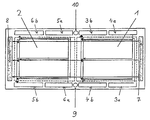
- FIG. 2 shows a flowfield structure according to the invention of a cell having two fields and an associated arrangement of the ports for inlet and outlet of the reactants and the cooling medium.
- the active cell surface (bipolar plate) is in this case—as the simplest variant—divided into just two fields ( 1 , 2 ), with at least one anode-side and cathode-side gas distributor structure (not shown) being present in each field.
- the fresh cathode gas enters the first field ( 1 ) through an entry port ( 4 a ), is partially depleted in the first field as a result of the fuel cell process which takes place and is then passed into the exit port ( 4 b ) of the field ( 1 ). Either there or in the subsequent entry port ( 6 a ) of the following field, it is mixed with fresh gas via a regulatable inlet port ( 9 ).
- the gas supply to the anode may be analogous to the flow guidance and gas mixing on the cathode side as described above.
- the fresh anode gas enters the first field ( 1 ) through an entry port ( 3 a ), is partially depleted in the first field as a result of the fuel cell process which takes place and is then passed into the exit port ( 3 b ) of the field ( 1 ). Either there or in the subsequent entry port ( 5 a ) of the following field ( 2 ), it is mixed with fresh gas via a regulatable inlet port ( 10 ). It is also possible for the latter two ports ( 3 b , 5 a ) to be combined or for the supply of fresh gas to be carried out in a separate space.
- the gas mixture formed from depleted gas of the preceding field ( 1 ) and the fresh gas then passes into the passage structure of the following field ( 2 ), where it is once again partially depleted by the fuel cell process taking place and is passed into the exit port ( 5 b ) of the field ( 2 ).
- Either the anode gas then leaves the stack or further fresh gas enrichment takes place in the manner described above for subsequent fields. Therefore, a plurality of fields are also conceivable on the anode side.
- the anode and/or cathode of the field ( 2 ) or of other fields can be directly supplied exclusively with unused gas.
- the gas streams of the individual fields can also be combined in such a way that the emerging cathode or anode gas streams of a plurality of fields, with or without fresh gas enrichment, are partially or completely passed into further fields.
- the emerging cathode or anode gas streams of a plurality of fields, with or without fresh gas enrichment are partially or completely passed into further fields.
- FIG. 2 merely provides one exit port ( 8 ) and one entry port ( 7 ) for all the fields of a cell.
- fields it is also possible for fields to be supplied using an additional entry and exit port for the cooling medium (not shown).
- the incoming and outgoing streams of cooling medium of the individual fields can be combined with one another.
- streams of cooling medium of certain fields it is possible for streams of cooling medium of certain fields to be either combined or split and then completely or partially introduced into a further field.
- passage structures which are diagrammatically depicted between the entry and exit ports represent just one possible configuration of the passage structure. In principle, serpentine-like, parallel, branched and/or studded structures are conceivable.
- the invention divides the cell into a plurality of fields allows the humidity level and the oxygen and/or hydrogen content of the cathode and anode gases to be distributed uniformly over the entire cell area. This makes it possible to reduce or eliminate the drying-out phenomenon. In addition, by targeted admixing of gas, it is also possible to influence the reaction distribution in the cell, so that formation of local hot spots can be largely avoided.
- the individual fields are for this purpose each equipped with temperature sensors. This allows the respective gas composition and/or the flow of coolant to be set to the optimum operating values as a function of the prevailing field temperature.
Abstract
Description
Claims (11)
Priority Applications (1)
| Application Number | Priority Date | Filing Date | Title |
|---|---|---|---|
| US13/068,750 US8039170B2 (en) | 2002-07-19 | 2011-05-19 | Internally gas regulated fuel cell |
Applications Claiming Priority (4)
| Application Number | Priority Date | Filing Date | Title |
|---|---|---|---|
| DE10232871A DE10232871A1 (en) | 2002-07-19 | 2002-07-19 | Fuel cell with internal gas regulation has distributor structure for feed channels for reagents of anode and/or cathode divided into at least two fields, each with input and output ports for reagents |
| DE10232871.4 | 2002-07-19 | ||
| DE10232871 | 2002-07-19 | ||
| PCT/DE2003/002201 WO2004017449A2 (en) | 2002-07-19 | 2003-07-02 | Internally gas regulated fuel cell |
Related Child Applications (1)
| Application Number | Title | Priority Date | Filing Date |
|---|---|---|---|
| US13/068,750 Division US8039170B2 (en) | 2002-07-19 | 2011-05-19 | Internally gas regulated fuel cell |
Publications (2)
| Publication Number | Publication Date |
|---|---|
| US20060014071A1 US20060014071A1 (en) | 2006-01-19 |
| US7972748B2 true US7972748B2 (en) | 2011-07-05 |
Family
ID=30010233
Family Applications (2)
| Application Number | Title | Priority Date | Filing Date |
|---|---|---|---|
| US10/523,067 Expired - Fee Related US7972748B2 (en) | 2002-07-19 | 2003-07-02 | Internally gas regulated fuel cell |
| US13/068,750 Expired - Fee Related US8039170B2 (en) | 2002-07-19 | 2011-05-19 | Internally gas regulated fuel cell |
Family Applications After (1)
| Application Number | Title | Priority Date | Filing Date |
|---|---|---|---|
| US13/068,750 Expired - Fee Related US8039170B2 (en) | 2002-07-19 | 2011-05-19 | Internally gas regulated fuel cell |
Country Status (6)
| Country | Link |
|---|---|
| US (2) | US7972748B2 (en) |
| EP (1) | EP1523781B1 (en) |
| JP (1) | JP4969040B2 (en) |
| CA (1) | CA2492923A1 (en) |
| DE (2) | DE10232871A1 (en) |
| WO (1) | WO2004017449A2 (en) |
Families Citing this family (8)
| Publication number | Priority date | Publication date | Assignee | Title |
|---|---|---|---|---|
| KR100637490B1 (en) * | 2004-09-17 | 2006-10-20 | 삼성에스디아이 주식회사 | Stack for fuel cell and fuel cell system with the same |
| EP1815548A2 (en) * | 2004-11-18 | 2007-08-08 | Behr GmbH & Co. KG | Device for carrying out a chemical reaction |
| JP4810872B2 (en) * | 2005-04-22 | 2011-11-09 | 株式会社エクォス・リサーチ | Fuel cell system |
| US20070077474A1 (en) * | 2005-10-04 | 2007-04-05 | Goebel Steven G | Fuel cell system water mass balancing scheme |
| JP2007264133A (en) * | 2006-03-27 | 2007-10-11 | Dainippon Printing Co Ltd | Method of manufacturing microlens formation film |
| KR101372027B1 (en) | 2012-12-28 | 2014-03-07 | 현대자동차주식회사 | Fuel cell stack |
| DE102013203311A1 (en) * | 2013-02-27 | 2014-08-28 | Bayerische Motoren Werke Aktiengesellschaft | The fuel cell system |
| KR102327544B1 (en) * | 2020-04-06 | 2021-11-17 | 한국자동차연구원 | Separator for fuel cell |
Citations (23)
| Publication number | Priority date | Publication date | Assignee | Title |
|---|---|---|---|---|
| EP0405088A1 (en) | 1989-05-03 | 1991-01-02 | Institute of Gas Technology | Fully internally manifolded fuel cell stack |
| JPH0668886A (en) | 1992-08-19 | 1994-03-11 | Fuji Electric Co Ltd | Cell structure of solid polymer electrolytic fuel cell |
| JPH0668896A (en) | 1992-08-20 | 1994-03-11 | Fuji Electric Co Ltd | Cell structure of solid polymer electrolytic fuel cell |
| JPH06119931A (en) | 1992-10-02 | 1994-04-28 | Mitsubishi Heavy Ind Ltd | Device of humidifying system for fuel cell |
| JPH0722059A (en) | 1993-06-29 | 1995-01-24 | Sanyo Electric Co Ltd | Flat solid electrolyte fuel cell |
| US5804326A (en) | 1996-12-20 | 1998-09-08 | Ballard Power Systems Inc. | Integrated reactant and coolant fluid flow field layer for an electrochemical fuel cell |
| JPH10284095A (en) | 1997-04-01 | 1998-10-23 | Fuji Electric Co Ltd | Solid high polymer electrolyte fuel cell |
| DE19743067A1 (en) | 1997-09-30 | 1999-04-01 | Ballard Power Systems | Flow module, especially fuel cell |
| JPH11312531A (en) | 1998-04-27 | 1999-11-09 | Toshiba Corp | Fuel cell system |
| JP2000012051A (en) | 1998-04-22 | 2000-01-14 | Toyota Motor Corp | Gas separator for fuel cell and fuel cell using the gas separator for the fuel cell |
| JP2000082482A (en) | 1998-06-26 | 2000-03-21 | Toyota Motor Corp | Gas separator for fuel cell and the fuel cell, and gas distributing method for fuel cell |
| JP2000090947A (en) | 1998-09-10 | 2000-03-31 | Honda Motor Co Ltd | Fuel cell |
| EP1009050A2 (en) | 1998-12-12 | 2000-06-14 | Adam Opel Ag | Fuel cell system, in particular for electric motor driven vehicles |
| JP2001043871A (en) | 1999-07-29 | 2001-02-16 | Aisin Seiki Co Ltd | Solid polymer electrolyte type fuel cell |
| JP2001143741A (en) | 1999-09-03 | 2001-05-25 | Honda Motor Co Ltd | Fuel cell stack |
| US6245453B1 (en) * | 1997-12-18 | 2001-06-12 | Toyota Jidosha Kabushiki Kaisha | Fuel cell and separator for the same |
| EP1109241A2 (en) | 1999-12-13 | 2001-06-20 | General Motors Corporation | Flow channels in current collector plates for fuel cells |
| JP2001185172A (en) | 1999-12-28 | 2001-07-06 | Honda Motor Co Ltd | Fuel cell and its operation |
| JP2001250568A (en) | 2000-03-03 | 2001-09-14 | Toyota Motor Corp | Collector panel for solid polymer fuel cell |
| US20020012827A1 (en) * | 1999-02-18 | 2002-01-31 | Toyota Jidosha Kabushiki Kaisha | Fuel cell, separator for the same and method for distributing gas in fuel cell |
| DE10055253A1 (en) | 2000-11-08 | 2002-05-29 | Daimler Chrysler Ag | fuel cell stack |
| US20030022052A1 (en) * | 2001-07-27 | 2003-01-30 | Kearl Daniel A. | Bipolar plates and end plates for fuel cells and methods for making the same |
| JP2004031135A (en) | 2002-06-26 | 2004-01-29 | Honda Motor Co Ltd | Fuel cell and its control method |
Family Cites Families (7)
| Publication number | Priority date | Publication date | Assignee | Title |
|---|---|---|---|---|
| JP3111697B2 (en) * | 1992-10-20 | 2000-11-27 | 富士電機株式会社 | Solid polymer electrolyte fuel cell |
| JP3424223B2 (en) * | 1995-03-29 | 2003-07-07 | マツダ株式会社 | Fuel cell stack structure |
| JP2001202981A (en) * | 2000-01-18 | 2001-07-27 | Mitsubishi Heavy Ind Ltd | System and method for fuel cell operation control |
| JP3921936B2 (en) * | 2000-11-09 | 2007-05-30 | トヨタ自動車株式会社 | Fuel cell gas flow path |
| JP2002367641A (en) * | 2001-06-08 | 2002-12-20 | Honda Motor Co Ltd | Fuel cell and driving method of the same |
| JP3963716B2 (en) * | 2001-12-13 | 2007-08-22 | 本田技研工業株式会社 | Fuel cell stack |
| JP4085668B2 (en) * | 2002-03-28 | 2008-05-14 | 松下電器産業株式会社 | Fuel cell |
-
2002
- 2002-07-19 DE DE10232871A patent/DE10232871A1/en not_active Ceased
-
2003
- 2003-07-02 JP JP2004528340A patent/JP4969040B2/en not_active Expired - Fee Related
- 2003-07-02 US US10/523,067 patent/US7972748B2/en not_active Expired - Fee Related
- 2003-07-02 CA CA002492923A patent/CA2492923A1/en not_active Abandoned
- 2003-07-02 DE DE50301518T patent/DE50301518D1/en not_active Expired - Lifetime
- 2003-07-02 WO PCT/DE2003/002201 patent/WO2004017449A2/en active IP Right Grant
- 2003-07-02 EP EP03787623A patent/EP1523781B1/en not_active Expired - Fee Related
-
2011
- 2011-05-19 US US13/068,750 patent/US8039170B2/en not_active Expired - Fee Related
Patent Citations (30)
| Publication number | Priority date | Publication date | Assignee | Title |
|---|---|---|---|---|
| EP0405088A1 (en) | 1989-05-03 | 1991-01-02 | Institute of Gas Technology | Fully internally manifolded fuel cell stack |
| DE69014155T2 (en) | 1989-05-03 | 1995-05-18 | Inst Gas Technology | Fuel cell stack with collecting channels completely arranged inside. |
| JPH0668886A (en) | 1992-08-19 | 1994-03-11 | Fuji Electric Co Ltd | Cell structure of solid polymer electrolytic fuel cell |
| JPH0668896A (en) | 1992-08-20 | 1994-03-11 | Fuji Electric Co Ltd | Cell structure of solid polymer electrolytic fuel cell |
| JPH06119931A (en) | 1992-10-02 | 1994-04-28 | Mitsubishi Heavy Ind Ltd | Device of humidifying system for fuel cell |
| JPH0722059A (en) | 1993-06-29 | 1995-01-24 | Sanyo Electric Co Ltd | Flat solid electrolyte fuel cell |
| US5804326A (en) | 1996-12-20 | 1998-09-08 | Ballard Power Systems Inc. | Integrated reactant and coolant fluid flow field layer for an electrochemical fuel cell |
| JP2001506399A (en) | 1996-12-20 | 2001-05-15 | バラード パワー システムズ インコーポレイティド | Integrated Reactant and Coolant Fluid Region Layer for Fuel Cell with Membrane Electrode Assembly |
| JPH10284095A (en) | 1997-04-01 | 1998-10-23 | Fuji Electric Co Ltd | Solid high polymer electrolyte fuel cell |
| DE19743067A1 (en) | 1997-09-30 | 1999-04-01 | Ballard Power Systems | Flow module, especially fuel cell |
| US6245453B1 (en) * | 1997-12-18 | 2001-06-12 | Toyota Jidosha Kabushiki Kaisha | Fuel cell and separator for the same |
| JP2000012051A (en) | 1998-04-22 | 2000-01-14 | Toyota Motor Corp | Gas separator for fuel cell and fuel cell using the gas separator for the fuel cell |
| JPH11312531A (en) | 1998-04-27 | 1999-11-09 | Toshiba Corp | Fuel cell system |
| JP2000082482A (en) | 1998-06-26 | 2000-03-21 | Toyota Motor Corp | Gas separator for fuel cell and the fuel cell, and gas distributing method for fuel cell |
| JP2000090947A (en) | 1998-09-10 | 2000-03-31 | Honda Motor Co Ltd | Fuel cell |
| US6294278B1 (en) | 1998-12-12 | 2001-09-25 | General Motors Corporation | Combination of low and high temperature fuel cell device |
| EP1009050A2 (en) | 1998-12-12 | 2000-06-14 | Adam Opel Ag | Fuel cell system, in particular for electric motor driven vehicles |
| US20020012827A1 (en) * | 1999-02-18 | 2002-01-31 | Toyota Jidosha Kabushiki Kaisha | Fuel cell, separator for the same and method for distributing gas in fuel cell |
| JP2001043871A (en) | 1999-07-29 | 2001-02-16 | Aisin Seiki Co Ltd | Solid polymer electrolyte type fuel cell |
| US6461754B1 (en) | 1999-07-29 | 2002-10-08 | Aisin Seiki Kabushiki Kaisha | Solid polymer electrolyte fuel cell having a coolant circulation circuit |
| JP2001143741A (en) | 1999-09-03 | 2001-05-25 | Honda Motor Co Ltd | Fuel cell stack |
| EP1109241A2 (en) | 1999-12-13 | 2001-06-20 | General Motors Corporation | Flow channels in current collector plates for fuel cells |
| JP2001185172A (en) | 1999-12-28 | 2001-07-06 | Honda Motor Co Ltd | Fuel cell and its operation |
| US6566001B2 (en) | 1999-12-28 | 2003-05-20 | Honda Giken Kogyo Kabushiki Kaisha | Solid polymer electrolyte fuel cell and non-humidifying operating method therefor |
| JP2001250568A (en) | 2000-03-03 | 2001-09-14 | Toyota Motor Corp | Collector panel for solid polymer fuel cell |
| DE10055253A1 (en) | 2000-11-08 | 2002-05-29 | Daimler Chrysler Ag | fuel cell stack |
| US20040053105A1 (en) | 2000-11-08 | 2004-03-18 | Felix Blank | Fuel cell stack |
| US20030022052A1 (en) * | 2001-07-27 | 2003-01-30 | Kearl Daniel A. | Bipolar plates and end plates for fuel cells and methods for making the same |
| JP2004031135A (en) | 2002-06-26 | 2004-01-29 | Honda Motor Co Ltd | Fuel cell and its control method |
| US7354670B2 (en) | 2002-06-26 | 2008-04-08 | Honda Giken Kosyo Kabushiki Kaisha | Fuel cell with fuel gas adjustment mechanism |
Non-Patent Citations (3)
| Title |
|---|
| Machine Translation and Abstract in English of JP 10-284095. * |
| Mizutani S. et al. ("Development of 1Kw Class PEFC Stack System with Function of Variable Gas Flow Channel", Proceedings of the Battery Symposium in Japan, vol. 1D17, Oct. 2, 2002, 518-519, XP008071986.). * |
| Translation in English of Mizutani S. et al. ("Development of 1Kw Class PEFC Stack System with Function of Variable Gas Flow Channel", Proceedings of the Battery Symposium in Japan, vol. 1D17, Oct. 2, 2002, 518-519, XP008071986.). * |
Also Published As
| Publication number | Publication date |
|---|---|
| US8039170B2 (en) | 2011-10-18 |
| CA2492923A1 (en) | 2004-02-26 |
| DE50301518D1 (en) | 2005-12-01 |
| EP1523781A2 (en) | 2005-04-20 |
| EP1523781B1 (en) | 2005-10-26 |
| US20060014071A1 (en) | 2006-01-19 |
| WO2004017449A2 (en) | 2004-02-26 |
| JP4969040B2 (en) | 2012-07-04 |
| US20110229779A1 (en) | 2011-09-22 |
| WO2004017449A3 (en) | 2004-04-29 |
| DE10232871A1 (en) | 2004-02-05 |
| JP2005537611A (en) | 2005-12-08 |
Similar Documents
| Publication | Publication Date | Title |
|---|---|---|
| US8039170B2 (en) | Internally gas regulated fuel cell | |
| US6755399B2 (en) | Humidifier | |
| US7820333B2 (en) | Fuel cell operating method with improved hydrogen and oxygen utilization | |
| US6376110B1 (en) | Method for regulating membrane moisture of a polymer electrolyte fuel cell, and a polymer electrolyte fuel cell | |
| US7829231B2 (en) | Fuel cell design with an integrated heat exchanger and gas humidification unit | |
| JP3654443B2 (en) | Fuel cell having built-in humidifier and method for humidifying fuel cell process gas | |
| US6723461B2 (en) | Water management system for fuel cell | |
| US20060263652A1 (en) | Fuel cell system relative humidity control | |
| CA2551674C (en) | Water management in fuel cells | |
| US20090053568A1 (en) | Evaporative Cooling of Fuel Cells Employing Antifreeze Solution | |
| US20050175869A1 (en) | Internal reforming fuel cell assembly with selectively adjustable direct and indirect internal reforming | |
| US7201990B2 (en) | Fuel cell stack | |
| US7465513B2 (en) | Matching of the local area-specific gas flows in PEM fuel cells | |
| CA2428317A1 (en) | Fuel cell stack | |
| JP4603920B2 (en) | Humidifier for fuel cell and fuel cell system provided with the same | |
| JP2004111397A (en) | Humidification of reactant stream in fuel cell | |
| US20060121323A1 (en) | Cathode saturation arrangement for fuel cell power plant | |
| US8021792B2 (en) | Fuel cell system having at least one fuel cell | |
| US20050037243A1 (en) | Method for operating a PEM fuel cell system, and associated PEM fuel cell system | |
| JP2004529458A (en) | Method for improving the moisture balance of a fuel cell | |
| CN114144913A (en) | Humidifier, fuel cell device with humidifier, and motor vehicle | |
| US20050003252A1 (en) | Passive water management system for a fuel cell power plant | |
| US9564644B2 (en) | Hydrating a fuel cell | |
| US20110033758A1 (en) | Porous flow field plate for moisture distribution control in a fuel cell | |
| KR20090095194A (en) | Hydrogenre circulation device for fuel cell system |
Legal Events
| Date | Code | Title | Description |
|---|---|---|---|
| AS | Assignment |
Owner name: DAIMLERCHRYSLER AG, GERMANY Free format text: ASSIGNMENT OF ASSIGNORS INTEREST;ASSIGNORS:BLANK, FELIX;HELLER, COSMAS;REEL/FRAME:016856/0458 Effective date: 20041223 |
|
| AS | Assignment |
Owner name: DAIMLER AG, GERMANY Free format text: CHANGE OF NAME;ASSIGNOR:DAIMLERCHRYSLER AG;REEL/FRAME:020442/0893 Effective date: 20071019 Owner name: DAIMLER AG,GERMANY Free format text: CHANGE OF NAME;ASSIGNOR:DAIMLERCHRYSLER AG;REEL/FRAME:020442/0893 Effective date: 20071019 |
|
| STCF | Information on status: patent grant |
Free format text: PATENTED CASE |
|
| FPAY | Fee payment |
Year of fee payment: 4 |
|
| FEPP | Fee payment procedure |
Free format text: MAINTENANCE FEE REMINDER MAILED (ORIGINAL EVENT CODE: REM.); ENTITY STATUS OF PATENT OWNER: LARGE ENTITY |
|
| LAPS | Lapse for failure to pay maintenance fees |
Free format text: PATENT EXPIRED FOR FAILURE TO PAY MAINTENANCE FEES (ORIGINAL EVENT CODE: EXP.); ENTITY STATUS OF PATENT OWNER: LARGE ENTITY |
|
| STCH | Information on status: patent discontinuation |
Free format text: PATENT EXPIRED DUE TO NONPAYMENT OF MAINTENANCE FEES UNDER 37 CFR 1.362 |
|
| FP | Lapsed due to failure to pay maintenance fee |
Effective date: 20190705 |