US8002575B2 - Cable assembly with strain relief member - Google Patents
Cable assembly with strain relief member Download PDFInfo
- Publication number
- US8002575B2 US8002575B2 US12/829,406 US82940610A US8002575B2 US 8002575 B2 US8002575 B2 US 8002575B2 US 82940610 A US82940610 A US 82940610A US 8002575 B2 US8002575 B2 US 8002575B2
- Authority
- US
- United States
- Prior art keywords
- cable
- strain relief
- relief member
- outer ring
- recited
- Prior art date
- Legal status (The legal status is an assumption and is not a legal conclusion. Google has not performed a legal analysis and makes no representation as to the accuracy of the status listed.)
- Expired - Fee Related
Links
Images


Classifications
-
- H—ELECTRICITY
- H01—ELECTRIC ELEMENTS
- H01R—ELECTRICALLY-CONDUCTIVE CONNECTIONS; STRUCTURAL ASSOCIATIONS OF A PLURALITY OF MUTUALLY-INSULATED ELECTRICAL CONNECTING ELEMENTS; COUPLING DEVICES; CURRENT COLLECTORS
- H01R13/00—Details of coupling devices of the kinds covered by groups H01R12/70 or H01R24/00 - H01R33/00
- H01R13/58—Means for relieving strain on wire connection, e.g. cord grip, for avoiding loosening of connections between wires and terminals within a coupling device terminating a cable
- H01R13/5804—Means for relieving strain on wire connection, e.g. cord grip, for avoiding loosening of connections between wires and terminals within a coupling device terminating a cable comprising a separate cable clamping part
- H01R13/5808—Means for relieving strain on wire connection, e.g. cord grip, for avoiding loosening of connections between wires and terminals within a coupling device terminating a cable comprising a separate cable clamping part formed by a metallic element crimped around the cable
-
- H—ELECTRICITY
- H01—ELECTRIC ELEMENTS
- H01R—ELECTRICALLY-CONDUCTIVE CONNECTIONS; STRUCTURAL ASSOCIATIONS OF A PLURALITY OF MUTUALLY-INSULATED ELECTRICAL CONNECTING ELEMENTS; COUPLING DEVICES; CURRENT COLLECTORS
- H01R13/00—Details of coupling devices of the kinds covered by groups H01R12/70 or H01R24/00 - H01R33/00
- H01R13/62—Means for facilitating engagement or disengagement of coupling parts or for holding them in engagement
- H01R13/629—Additional means for facilitating engagement or disengagement of coupling parts, e.g. aligning or guiding means, levers, gas pressure electrical locking indicators, manufacturing tolerances
- H01R13/633—Additional means for facilitating engagement or disengagement of coupling parts, e.g. aligning or guiding means, levers, gas pressure electrical locking indicators, manufacturing tolerances for disengagement only
- H01R13/6335—Additional means for facilitating engagement or disengagement of coupling parts, e.g. aligning or guiding means, levers, gas pressure electrical locking indicators, manufacturing tolerances for disengagement only comprising a handle
-
- H—ELECTRICITY
- H01—ELECTRIC ELEMENTS
- H01R—ELECTRICALLY-CONDUCTIVE CONNECTIONS; STRUCTURAL ASSOCIATIONS OF A PLURALITY OF MUTUALLY-INSULATED ELECTRICAL CONNECTING ELEMENTS; COUPLING DEVICES; CURRENT COLLECTORS
- H01R9/00—Structural associations of a plurality of mutually-insulated electrical connecting elements, e.g. terminal strips or terminal blocks; Terminals or binding posts mounted upon a base or in a case; Bases therefor
- H01R9/03—Connectors arranged to contact a plurality of the conductors of a multiconductor cable, e.g. tapping connections
-
- H—ELECTRICITY
- H01—ELECTRIC ELEMENTS
- H01R—ELECTRICALLY-CONDUCTIVE CONNECTIONS; STRUCTURAL ASSOCIATIONS OF A PLURALITY OF MUTUALLY-INSULATED ELECTRICAL CONNECTING ELEMENTS; COUPLING DEVICES; CURRENT COLLECTORS
- H01R13/00—Details of coupling devices of the kinds covered by groups H01R12/70 or H01R24/00 - H01R33/00
- H01R13/46—Bases; Cases
- H01R13/502—Bases; Cases composed of different pieces
- H01R13/512—Bases; Cases composed of different pieces assembled by screw or screws
-
- H—ELECTRICITY
- H01—ELECTRIC ELEMENTS
- H01R—ELECTRICALLY-CONDUCTIVE CONNECTIONS; STRUCTURAL ASSOCIATIONS OF A PLURALITY OF MUTUALLY-INSULATED ELECTRICAL CONNECTING ELEMENTS; COUPLING DEVICES; CURRENT COLLECTORS
- H01R13/00—Details of coupling devices of the kinds covered by groups H01R12/70 or H01R24/00 - H01R33/00
- H01R13/648—Protective earth or shield arrangements on coupling devices, e.g. anti-static shielding
- H01R13/658—High frequency shielding arrangements, e.g. against EMI [Electro-Magnetic Interference] or EMP [Electro-Magnetic Pulse]
- H01R13/6581—Shield structure
- H01R13/6582—Shield structure with resilient means for engaging mating connector
- H01R13/6583—Shield structure with resilient means for engaging mating connector with separate conductive resilient members between mating shield members
- H01R13/6584—Shield structure with resilient means for engaging mating connector with separate conductive resilient members between mating shield members formed by conductive elastomeric members, e.g. flat gaskets or O-rings
-
- H—ELECTRICITY
- H01—ELECTRIC ELEMENTS
- H01R—ELECTRICALLY-CONDUCTIVE CONNECTIONS; STRUCTURAL ASSOCIATIONS OF A PLURALITY OF MUTUALLY-INSULATED ELECTRICAL CONNECTING ELEMENTS; COUPLING DEVICES; CURRENT COLLECTORS
- H01R13/00—Details of coupling devices of the kinds covered by groups H01R12/70 or H01R24/00 - H01R33/00
- H01R13/66—Structural association with built-in electrical component
- H01R13/665—Structural association with built-in electrical component with built-in electronic circuit
- H01R13/6658—Structural association with built-in electrical component with built-in electronic circuit on printed circuit board
-
- H—ELECTRICITY
- H01—ELECTRIC ELEMENTS
- H01R—ELECTRICALLY-CONDUCTIVE CONNECTIONS; STRUCTURAL ASSOCIATIONS OF A PLURALITY OF MUTUALLY-INSULATED ELECTRICAL CONNECTING ELEMENTS; COUPLING DEVICES; CURRENT COLLECTORS
- H01R24/00—Two-part coupling devices, or either of their cooperating parts, characterised by their overall structure
- H01R24/60—Contacts spaced along planar side wall transverse to longitudinal axis of engagement
- H01R24/62—Sliding engagements with one side only, e.g. modular jack coupling devices
Definitions
- the present invention generally relates to a cable assembly, and more particular to a cable assembly with a strain relief member.
- a cable assembly member commonly includes a connector coupled to a cable.
- a strain relief member is mounted to the cable to prevent it from being damaged.
- U.S. Pat. No. 5,383,796 discloses an electrical connector which includes a shell having a cavity and a cable-receiving opening adapted to receive an electrical cable. The opening defines an axis, and two screw posts are located in the cavity spaced on opposite sides of the axis such that the cable can be positioned therebetween.
- a cable clamp member includes a center section adapted to embrace one side of the cable, and a pair of wing sections extending from the center section and having screw-receiving holes aligning with the screw posts.
- the clamp member includes flanges projecting from the wing sections, with the flanges having slots for embracing ribs on the shell to preposition the cable clamp member over the cable with the screw-receiving holes aligned with the screw posts.
- the cable clamp member may crush cable if the screw posts are tightened excessively.
- CN Pat. No. 2891361 discloses a cable assembly with a strain relief member.
- the strain relief member has a U shaped retainer and a ring member which are made of metallic materials.
- the ring member is mounted onto metallic braiding of the cable assembly and the retainer grips the ring member.
- the retainer is positioned in an insulative housing of the cable assembly.
- an object of the present invention is to provide a cable assembly with an improved strain relief member.
- a cable assembly in accordance with the present invention comprises a housing having a main portion and a mounting portion extending backwardly from the main portion, the mounting portion defining a positioning cavity in an inner side thereof; a cable having a number of wires and a jacket, the wires enclosed by the jacket; a strain relief member having an inner ring and an outer ring connected with each other to form a one-piece structure; and the strain relief member mounted to a front segment of the cable, the wires of the cable forwardly extending through the inner ring, the jacket of the cable sandwiched between the outer ring and the inner ring, the outer ring accommodated in the positioning cavity of the mounting portion.
- FIG. 1 is an assembled view of a cable assembly of the first embodiment in accordance with the present invention
- FIG. 2 is an exploded, perspective view of the cable assembly in FIG. 1 ;
- FIG. 3 is similar to FIG. 2 , but viewed from another aspect
- FIG. 4 shows a strain relief member mounted to a cable of the cable assembly
- FIG. 5 is partially assembled view of the cable assembly
- FIG. 6 is cross section view of the cable assembly taken along line 6 - 6 ;
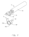
- FIG. 7 illustrates a strain relief member and a cable of a cable assembly of the second embodiment in accordance with the present invention
- FIG. 8 shows the strain relief member mounted to the cable of the cable assembly
- FIG. 9 shows the strain relief member is crimped to the cable.
- a cable assembly 100 of the first embodiment in accordance with the present invention comprises a connector and a cable 4 connected to the connector.
- the connector includes a printed circuit board (PCB) 3 inside an elongated housing which has a cage 1 and a cover 2 .
- the cable assembly 100 further includes a metallic gasket 5 , an ejecting mechanism and a strain relief member 7 .
- the cage 1 is a die-cast member and has a first main portion 11 and a first mounting portion 12 extending backwardly from the main portion 11 .
- the first main portion 11 has a pair of side walls 111 , 112 and a bottom walls 113 joining with the side walls 111 , 112 to define a receiving space 110 .
- Two first depressions 1110 are defined in back segments of peripherals of the side walls 111 , 112 .
- a front segment of the bottom wall 113 is cut to form a cutout 1131
- a first channel 1132 is defined in outside of a back segment of the bottom wall 113 .
- a protrusion 1133 is located in the front portion of the first channel 1132 .
- Two L-shaped cavities 1134 are arranged at opposite sides of the first channel 1132 .
- a tiny post 1135 is located in a front corner of the L-shaped cavity 1134 .
- a beam 114 is connected to front ends of the two side walls 111 , 112 .
- the first mounting portion 12 has two lateral walls 121 and a lower wall 122 extending backwardly from the pair of side walls 111 , 112 and a bottom walls 113 .
- a semicircular shaped outlet 1201 is arranged between the pair of side walls 121 and the lower wall 122 .
- a positioning cavity 1202 is disposed in front of the outlet 1201 .
- a second channel 1221 is defined in an outside of the lower wall 122 and communicates with the first channel 1132 .
- Two guiding rails 123 are formed on the outside of the lower wall 122 and located at opposite sides of the second channel 1221 .
- a guiding passage 1232 is defined in a front segment of the guiding rail 123 and a guiding tab 1231 is formed on inner side of a back segment of the guiding rail 123 .
- Two poles 1211 are formed on outsides of the lateral walls 121 , respectively.
- Two screw holes 1212 are recessed downwardly from top surfaces of the lateral walls 121 .
- the cover 2 is a die-cast member and includes a second main portion 21 and a second mounting portion 22 extending backward from the second main portion 21 .
- the second main portion 21 has a planar base 213 and two flanges 211 , 212 project downwardly from lateral sides of the base 213 .
- a second depression 2130 is defined in back segment of the base 213 .
- a vertical member 2131 projects downwardly from lower surface of the front segment of the base 213 .
- Two juxtaposed supporting members 2133 are located behind the vertical member 2131 , and each supporting member 2133 further defines a screw hole 2134 .
- An engaging member 2132 is attached to a front end of the base 213 .
- the second mounting portion 22 has two lateral walls 221 and a lower wall 222 .
- a semicircular shaped outlet 2201 is arranged between the pair of side walls 221 and the lower wall 222 .
- a positioning cavity 2202 is disposed in front of the outlet 2201 .
- the PCB 3 includes a substrate 30 , a plurality of first conductive pads 31 formed on a front segment of the substrate 30 , a plurality of second conductive pads 32 formed on a rear segment of the substrate 30 .
- Two holes 33 are defined in the substrate 30 and proximate to the front segment thereof.
- the cable 4 includes a number of wires 41 enclosed within a jacket 40 .
- Each of the wires 41 has an inner conductor 42 .
- the metallic gasket 5 is a rectangular shaped frame member 51 , and includes two upstanding portions 501 , 502 with an upper portion 503 joining with top edges of the two upstanding portions 501 , 502 , and two lower portions 504 inwardly projecting from bottom edges of the two upstanding portions 501 , 502 .
- the two lower portions 504 are separated by a gap 50 .
- a plurality of fingers 52 , 53 are attached to the two upstanding portions 501 , 502 and the upper portion 503 .
- the fingers 52 , 53 are arranged into an outer layer and an inner layer and further overlapped with each other.
- Two attachment portions 54 are respectively connected to the two lower portions 504 and extend into the gap 50 .
- Each of the attachment portion 54 further defines a hole 541 .
- the ejecting mechanism 6 includes a slider 61 , an actuator 62 and a fastening member 63 .
- the slider 61 has a main portion 611 and two wedged arms 612 projecting forwardly from the main portion 611 .
- a cutout 6120 is formed between the two wedged arms 612 .
- Two slots 613 are defined in back sections of lateral sides of the main portion 611 .
- a transversal hole 614 is defined in middle segment of the main portion 611 .
- the actuator 62 includes a horizontal beam 621 and two legs 622 extending downwardly from opposite ends of the horizontal beam 621 .
- An operating portion 623 protrudes upwardly from back edge of the horizontal beam 621 .
- a first hole 6221 is defined in a middle segment of the leg 622 and a second hole 6222 is defined in a lower segment of the leg 622 .
- the fastening member 63 includes a bolt 631 and a nut 632 .
- the strain relief member 7 is one-piece structure and lathed by a copper rod or other metallic rod.
- the strain relief member 7 includes an inner ring 71 and an outer ring 72 .
- the inner ring 71 and the outer ring 72 are coaxially arranged and connected with each other by circular/annular portion 73 to form a one-piece strain relief member 7 .
- the jacket 40 is sandwiched between the inner ring 71 and the outer ring 72 , while the wires 41 pass though the inner ring 71 .
- the PCB 3 is supported by the supporting members 2133 of the cover 2 and two screws 81 are inserted into the holes 33 of the PCB and further assembled to the screw holes 2134 of the supporting members 2133 .
- the outer ring 72 of the strain relief member 7 is put into the positioning cavity 2202 , and the cable 4 backwardly extends outward via the outlet 2201 .
- the cover 2 is assembled to the cage 1 , with the flanges 211 , 212 inserted into receiving space 110 , the engaging member 2132 engaged with the beam 114 of the cage 1 .
- the PCB 3 is accommodated in the receiving space 110 .
- the strain relief member 7 is received in the positioning cavity 1202 .
- Two screws 82 are inserted into the two through holes 2211 and assembled to the two screw holes 1212 .
- the strain relief member 7 is reliably held by the positioning cavities 1202 , 2202 .
- the gasket 5 is mounted to peripheral of the first main portion 11 and the second main portion 21 and further disposed in front of the strain relief member 7 , with the two upstanding portions 501 , 502 accommodated in the two first depressions 1110 and the upper portion 503 accommodated in the second depression 2130 , the two lower portions 504 accommodated in the L-shaped cavities 1134 , and the posts 1135 engage with holes 541 in the attachment portion 54 .
- the slider 61 is mounted to the second channel 1221 , with the guiding tabs 1231 respectively inserted into the slots 613 , the transversal hole 614 aligned with the guiding passage 1232 .
- the actuator 62 is assembled to the first mounting portion 12 , with the first hole 6221 pivotally engaged with the two poles 1211 , respectively, and the second hole 6222 aligned with the guiding passage 1232 to let the bolt 631 passing therethrough.
- the actuator 62 can be rocked to push the slider 61 forwardly move to detach/separate the cable assembly 100 from the complementary connector (not shown).
- the strain relief member 7 ′ is a one-piece structure and punched by a metallic sheet.
- the strain relief member 7 ′ includes an inner ring 71 ′ and an outer ring 72 ′ connected with the inner ring 71 ′ by a connection portion 73 ′.
- the outer ring 72 ′ is opened along an axial direction to form a U-shaped contour.
- the strain relief member 7 ′ is mounted to a front portion of the cable 4 , with the wires 41 extending through the inner ring 71 ′ and the jacket 40 sandwiched between the inner ring 71 ′ and the outer ring 72 ′ after the outer ring 72 ′ is crimped.
- Other elements and relations therebetween of the cable assembly of the second embodiment are similar to the cable assembly 100 of the first embodiment, and detailed description is omitted hereby.
- the cable 4 further includes a metallic braiding inside the jacket 40 and outside the wires 41 .
- the jacket 40 and the metallic braiding both are sandwiched between the inner ring 41 and the outer ring 42 .
- the outer ring 72 may be polygonal sides, e.g. six sides, eight sides.
Abstract
Description
Claims (20)
Applications Claiming Priority (2)
| Application Number | Priority Date | Filing Date | Title |
|---|---|---|---|
| CN200910303952XA CN101938061B (en) | 2009-07-02 | 2009-07-02 | Cable connector assembly |
| CN200910303952.X | 2009-07-02 |
Publications (2)
| Publication Number | Publication Date |
|---|---|
| US20110003502A1 US20110003502A1 (en) | 2011-01-06 |
| US8002575B2 true US8002575B2 (en) | 2011-08-23 |
Family
ID=43391262
Family Applications (1)
| Application Number | Title | Priority Date | Filing Date |
|---|---|---|---|
| US12/829,406 Expired - Fee Related US8002575B2 (en) | 2009-07-02 | 2010-07-02 | Cable assembly with strain relief member |
Country Status (2)
| Country | Link |
|---|---|
| US (1) | US8002575B2 (en) |
| CN (1) | CN101938061B (en) |
Cited By (8)
| Publication number | Priority date | Publication date | Assignee | Title |
|---|---|---|---|---|
| US20120190224A1 (en) * | 2011-01-21 | 2012-07-26 | Hon Hai Precision Industry Co., Ltd. | Electronic module with improved latch mechanism |
| US20130316561A1 (en) * | 2012-05-25 | 2013-11-28 | Weetech Gmbh | Variable plug of a connector |
| US8777643B2 (en) * | 2012-08-16 | 2014-07-15 | Hubbell Incorporated | Ground strap shield connector |
| US20160190759A1 (en) * | 2014-12-31 | 2016-06-30 | Syncmold Enterprise Corp. | Method of manufacturing dock |
| US9515415B1 (en) * | 2015-07-29 | 2016-12-06 | Tyco Electronics Corporation | Strain relief cable insert |
| US20180097300A1 (en) * | 2016-09-30 | 2018-04-05 | Japan Aviation Electronics Industry, Limited | Cable connection structural body and cable connector |
| USD860139S1 (en) | 2017-09-11 | 2019-09-17 | Methode Electronics, Inc. | Pluggable module |
| US10483707B2 (en) | 2016-09-09 | 2019-11-19 | Methode Electronics, Inc. | Pluggable module with coaxial connector interface |
Families Citing this family (13)
| Publication number | Priority date | Publication date | Assignee | Title |
|---|---|---|---|---|
| CN201708273U (en) * | 2010-05-12 | 2011-01-12 | 富士康(昆山)电脑接插件有限公司 | Component of electric connector |
| SG181191A1 (en) * | 2010-11-23 | 2012-06-28 | 3M Innovative Properties Co | A gasket for an emi connector |
| CN102610960B (en) * | 2011-01-20 | 2014-12-24 | 富士康(昆山)电脑接插件有限公司 | Electric connector assembly |
| CN102496804A (en) * | 2011-11-22 | 2012-06-13 | 华为终端有限公司 | USB (universal serial bus) connector and electronic equipment |
| CN105403964B (en) * | 2015-12-04 | 2017-11-07 | 青岛海信宽带多媒体技术有限公司 | A kind of pluggable optical module |
| CN105403962B (en) * | 2015-12-08 | 2017-09-12 | 青岛海信宽带多媒体技术有限公司 | A kind of optical module |
| US9746625B2 (en) | 2015-12-04 | 2017-08-29 | Hisense Broadband Multimedia Technologies Co., Ltd. | Optical module |
| US10193268B1 (en) * | 2017-10-31 | 2019-01-29 | Teralux Technology Co., Ltd. | SFP cable connector capable of protecting solder joints |
| JP7206906B2 (en) * | 2018-12-28 | 2023-01-18 | 株式会社オートネットワーク技術研究所 | Terminal modules and connectors |
| CN111380570B (en) * | 2018-12-28 | 2022-05-03 | 霍尼韦尔国际公司 | Devices, systems, and methods for improved sensor wire retention |
| USD948456S1 (en) * | 2019-08-08 | 2022-04-12 | Optoway Technology Inc. | Small form-factor pluggable module |
| JP7256214B2 (en) * | 2021-01-08 | 2023-04-11 | 矢崎総業株式会社 | wire harness |
| CN113241537B (en) * | 2021-07-08 | 2021-09-14 | 广东电网有限责任公司东莞供电局 | Automatic wiring device for electric power cables |
Citations (9)
| Publication number | Priority date | Publication date | Assignee | Title |
|---|---|---|---|---|
| US5383796A (en) | 1993-11-24 | 1995-01-24 | Molex Incorporated | Electrical connector with improved strain relief means |
| US6152746A (en) * | 1997-09-12 | 2000-11-28 | Itt Manufacturing Enterprises, Inc. | Screened cable terminating ferrule |
| US20030171016A1 (en) * | 2002-03-06 | 2003-09-11 | Bright Edward John | Transceiver module assembly ejector mechanism |
| US6648690B2 (en) * | 2001-01-17 | 2003-11-18 | Yazaki Corporation | Terminal end structure for shielded wire |
| US7044756B1 (en) * | 2004-12-03 | 2006-05-16 | Yazaki Corporation | Method of grounding shielded wire and structure for grounding shielded wire |
| US7090523B2 (en) * | 2004-01-06 | 2006-08-15 | Tyco Electronics Corporation | Release mechanism for transceiver module assembly |
| CN2891361Y (en) | 2005-03-01 | 2007-04-18 | 富士康(昆山)电脑接插件有限公司 | Cable connector assembly |
| US20080031577A1 (en) * | 2001-12-06 | 2008-02-07 | Finisar Corporation | Method and system for releasing a pluggable module |
| US7815445B2 (en) * | 2008-07-18 | 2010-10-19 | Hon Hai Precision Ind. Co., Ltd. | High-speed cable assembly with protective member |
Family Cites Families (1)
| Publication number | Priority date | Publication date | Assignee | Title |
|---|---|---|---|---|
| US7364465B2 (en) * | 2005-08-11 | 2008-04-29 | Hon Hai Precision Ind. Co., Ltd. | Plug connector with improved strain relief member |
-
2009
- 2009-07-02 CN CN200910303952XA patent/CN101938061B/en not_active Expired - Fee Related
-
2010
- 2010-07-02 US US12/829,406 patent/US8002575B2/en not_active Expired - Fee Related
Patent Citations (12)
| Publication number | Priority date | Publication date | Assignee | Title |
|---|---|---|---|---|
| US5383796A (en) | 1993-11-24 | 1995-01-24 | Molex Incorporated | Electrical connector with improved strain relief means |
| US6152746A (en) * | 1997-09-12 | 2000-11-28 | Itt Manufacturing Enterprises, Inc. | Screened cable terminating ferrule |
| US6648690B2 (en) * | 2001-01-17 | 2003-11-18 | Yazaki Corporation | Terminal end structure for shielded wire |
| US20080031577A1 (en) * | 2001-12-06 | 2008-02-07 | Finisar Corporation | Method and system for releasing a pluggable module |
| US20030171016A1 (en) * | 2002-03-06 | 2003-09-11 | Bright Edward John | Transceiver module assembly ejector mechanism |
| US6749448B2 (en) * | 2002-03-06 | 2004-06-15 | Tyco Electronics Corporation | Transceiver module assembly ejector mechanism |
| US6752663B2 (en) * | 2002-03-06 | 2004-06-22 | Tyco Electronics Corporation | Receptacle assembly having shielded receptacle connector interface with pluggable electronic module |
| US7001217B2 (en) * | 2002-03-06 | 2006-02-21 | Tyco Electronics Corporation | Receptacle assembly having shielded interface with pluggable electronic module |
| US7090523B2 (en) * | 2004-01-06 | 2006-08-15 | Tyco Electronics Corporation | Release mechanism for transceiver module assembly |
| US7044756B1 (en) * | 2004-12-03 | 2006-05-16 | Yazaki Corporation | Method of grounding shielded wire and structure for grounding shielded wire |
| CN2891361Y (en) | 2005-03-01 | 2007-04-18 | 富士康(昆山)电脑接插件有限公司 | Cable connector assembly |
| US7815445B2 (en) * | 2008-07-18 | 2010-10-19 | Hon Hai Precision Ind. Co., Ltd. | High-speed cable assembly with protective member |
Cited By (13)
| Publication number | Priority date | Publication date | Assignee | Title |
|---|---|---|---|---|
| US20120190224A1 (en) * | 2011-01-21 | 2012-07-26 | Hon Hai Precision Industry Co., Ltd. | Electronic module with improved latch mechanism |
| US8668515B2 (en) * | 2011-01-21 | 2014-03-11 | Hon Hai Precision Industry Co., Ltd. | Electronic module with improved latch mechanism |
| US20130316561A1 (en) * | 2012-05-25 | 2013-11-28 | Weetech Gmbh | Variable plug of a connector |
| US9065193B2 (en) * | 2012-05-25 | 2015-06-23 | Weetech Gmbh | Variable plug of a connector |
| US8777643B2 (en) * | 2012-08-16 | 2014-07-15 | Hubbell Incorporated | Ground strap shield connector |
| US20160190759A1 (en) * | 2014-12-31 | 2016-06-30 | Syncmold Enterprise Corp. | Method of manufacturing dock |
| US9515415B1 (en) * | 2015-07-29 | 2016-12-06 | Tyco Electronics Corporation | Strain relief cable insert |
| US10483707B2 (en) | 2016-09-09 | 2019-11-19 | Methode Electronics, Inc. | Pluggable module with coaxial connector interface |
| US11223173B2 (en) | 2016-09-09 | 2022-01-11 | Methode Electronics Inc. | Pluggable module with coaxial connector interface |
| US20180097300A1 (en) * | 2016-09-30 | 2018-04-05 | Japan Aviation Electronics Industry, Limited | Cable connection structural body and cable connector |
| US10411374B2 (en) * | 2016-09-30 | 2019-09-10 | Japan Aviation Electronics Industry, Limited | Cable connection structural body and cable connector |
| USD860139S1 (en) | 2017-09-11 | 2019-09-17 | Methode Electronics, Inc. | Pluggable module |
| USD883226S1 (en) | 2017-09-11 | 2020-05-05 | Methode Electronics, Inc. | Pluggable module |
Also Published As
| Publication number | Publication date |
|---|---|
| CN101938061B (en) | 2013-11-13 |
| US20110003502A1 (en) | 2011-01-06 |
| CN101938061A (en) | 2011-01-05 |
Similar Documents
| Publication | Publication Date | Title |
|---|---|---|
| US8002575B2 (en) | Cable assembly with strain relief member | |
| US6663415B1 (en) | Electrical connector assembly with improved strain relief | |
| US8333616B2 (en) | Low-profile cable assembly with good function EMI prevention | |
| US8480432B2 (en) | Electrical connector assembly having two spaced internal printed circuit boards and an external metallic gasket | |
| US7226316B2 (en) | Cable connector assembly with holder | |
| US8550848B2 (en) | Electrical connector assembly having an improved EMI gasket | |
| US8221160B2 (en) | Connector assembly having grounding means | |
| JP4909793B2 (en) | Shield connector | |
| US8070517B2 (en) | Electrical connector having an improved spring member for abutting against a metal plate | |
| US6129594A (en) | Electrical connector | |
| US20060228931A1 (en) | Electrical cable assembly having cable guide | |
| US6346009B1 (en) | Shielded multiple electrical connector assembly | |
| US8011961B2 (en) | Cable assembly with grounding pieces | |
| CN101552390B (en) | Connector with a shielding-screen support | |
| US20100068922A1 (en) | Cable connector assembly having improved grounding member | |
| US10381776B2 (en) | Connector assembly with an improved latch member having a shorter length | |
| JP2007157594A (en) | Connector | |
| US20110143590A1 (en) | Connector assembly having grounding means | |
| US20120315800A1 (en) | Electrical connector | |
| US7931493B2 (en) | Cable assembly with a firm connection between a plurality of wires and a connector | |
| JP2003272785A (en) | Electric connector | |
| US8007324B2 (en) | Electrical connector with improved fastening device | |
| US6755671B1 (en) | Electrical connector having improved ground structure | |
| US6764340B2 (en) | Shielded connector assembly | |
| JP2008147020A (en) | Electric connector, its assembly, and assembly method of electric connector |
Legal Events
| Date | Code | Title | Description |
|---|---|---|---|
| AS | Assignment |
Owner name: HON HAI PRECISION INDUSTRY CO., LTD., TAIWAN Free format text: ASSIGNMENT OF ASSIGNORS INTEREST;ASSIGNORS:LI, XIAO-LI;SU, PING-SHENG;REEL/FRAME:024628/0717 Effective date: 20100620 |
|
| STCF | Information on status: patent grant |
Free format text: PATENTED CASE |
|
| FPAY | Fee payment |
Year of fee payment: 4 |
|
| FEPP | Fee payment procedure |
Free format text: MAINTENANCE FEE REMINDER MAILED (ORIGINAL EVENT CODE: REM.); ENTITY STATUS OF PATENT OWNER: LARGE ENTITY |
|
| LAPS | Lapse for failure to pay maintenance fees |
Free format text: PATENT EXPIRED FOR FAILURE TO PAY MAINTENANCE FEES (ORIGINAL EVENT CODE: EXP.); ENTITY STATUS OF PATENT OWNER: LARGE ENTITY |
|
| STCH | Information on status: patent discontinuation |
Free format text: PATENT EXPIRED DUE TO NONPAYMENT OF MAINTENANCE FEES UNDER 37 CFR 1.362 |
|
| FP | Expired due to failure to pay maintenance fee |
Effective date: 20190823 |