US8004673B2 - Photometric instrument - Google Patents
Photometric instrument Download PDFInfo
- Publication number
- US8004673B2 US8004673B2 US12/292,444 US29244408A US8004673B2 US 8004673 B2 US8004673 B2 US 8004673B2 US 29244408 A US29244408 A US 29244408A US 8004673 B2 US8004673 B2 US 8004673B2
- Authority
- US
- United States
- Prior art keywords
- light
- structures
- substrate
- instrument according
- photometric instrument
- Prior art date
- Legal status (The legal status is an assumption and is not a legal conclusion. Google has not performed a legal analysis and makes no representation as to the accuracy of the status listed.)
- Expired - Fee Related, expires
Links
Images


Classifications
-
- G—PHYSICS
- G01—MEASURING; TESTING
- G01N—INVESTIGATING OR ANALYSING MATERIALS BY DETERMINING THEIR CHEMICAL OR PHYSICAL PROPERTIES
- G01N21/00—Investigating or analysing materials by the use of optical means, i.e. using sub-millimetre waves, infrared, visible or ultraviolet light
- G01N21/62—Systems in which the material investigated is excited whereby it emits light or causes a change in wavelength of the incident light
- G01N21/63—Systems in which the material investigated is excited whereby it emits light or causes a change in wavelength of the incident light optically excited
- G01N21/64—Fluorescence; Phosphorescence
- G01N21/645—Specially adapted constructive features of fluorimeters
- G01N21/648—Specially adapted constructive features of fluorimeters using evanescent coupling or surface plasmon coupling for the excitation of fluorescence
-
- G—PHYSICS
- G01—MEASURING; TESTING
- G01N—INVESTIGATING OR ANALYSING MATERIALS BY DETERMINING THEIR CHEMICAL OR PHYSICAL PROPERTIES
- G01N21/00—Investigating or analysing materials by the use of optical means, i.e. using sub-millimetre waves, infrared, visible or ultraviolet light
- G01N21/62—Systems in which the material investigated is excited whereby it emits light or causes a change in wavelength of the incident light
- G01N21/63—Systems in which the material investigated is excited whereby it emits light or causes a change in wavelength of the incident light optically excited
- G01N21/64—Fluorescence; Phosphorescence
- G01N21/645—Specially adapted constructive features of fluorimeters
- G01N21/6456—Spatial resolved fluorescence measurements; Imaging
-
- G—PHYSICS
- G01—MEASURING; TESTING
- G01N—INVESTIGATING OR ANALYSING MATERIALS BY DETERMINING THEIR CHEMICAL OR PHYSICAL PROPERTIES
- G01N21/00—Investigating or analysing materials by the use of optical means, i.e. using sub-millimetre waves, infrared, visible or ultraviolet light
- G01N21/62—Systems in which the material investigated is excited whereby it emits light or causes a change in wavelength of the incident light
- G01N21/63—Systems in which the material investigated is excited whereby it emits light or causes a change in wavelength of the incident light optically excited
- G01N21/64—Fluorescence; Phosphorescence
- G01N2021/6417—Spectrofluorimetric devices
- G01N2021/6423—Spectral mapping, video display
Definitions
- the present invention relates to a photometric instrument.
- a photometric instrument which photometrically analyzes biopolymer by irradiating the biopolymer with light.
- JP-A 9-257813 Japanese Patent Application Publication No. Hei 9-257813
- JP-A 9-257813 there is described an instrument which irradiates a transparent substrate with excitation light emitted from an excitation source, generates evanescent waves on a surface of the substrate by totally reflecting the excitation light inside the substrate, and detects scattered light of the evanescent waves from a specimen on the substrate.
- the scattered light is not spectrally separated.
- JP-A 2005-70031 describes an instrument for spectrally separating fluorescence and scattered light which come from specimen components excited by evanescent waves.
- the specimen components are not fixed on a boundary surface of a flow path.
- unlabeled single-stranded DNA is fixed on the substrate at the beginning, and a sequence of the fixed DNA can be read by: introducing thereon a reaction solution containing fluorescent-labeled base species respectively labeled with different phosphors; and spectrally separating fluorescence originating from molecule fixation positions while bonding the single-stranded DNA to its complementary bases.
- an instrument for analyzing biomolecules through imaging of fluorescence of the biomolecules fixed on a surface of a substrate generally, different kinds of biomolecules are respectively fixed on different spots on the substrate, and fluorescence from the respective spots is separated and then detected through the imaging.
- it is favorable to form spots so that the biomolecules can be fixed on the substrate as densely as possible to the extent allowing optical resolution thereof.
- it is more advantageous to fix a smaller number of biomolecules in one spot, and the number is ideally one.
- a fluorescence detection method has a sufficient sensitivity for detecting even one molecule
- a spectral imaging method causing only a smaller loss is preferable for the purpose of obtaining a favorable S/N ratio in spectroscopically detecting fluorescence from a small number of molecules.
- preferable methods for this purpose are a dispersive spectral imaging method using a dispersing element such as a prism or a diffraction grating, and a method (dichroic/multi-sensor spectral imaging method) in which multiple image sensors respectively acquires images from light spectrally separated by a dichroic mirror.
- the dispersive spectral imaging method has the following problem because a change in wavelength of fluorescence is converted into a change in spot image positions in a fluorescence image. More specifically, there is a case where, even though one species of phosphors of plural species having different luminous wavelengths have emitted fluorescence, which species of the phosphors has emitted the fluorescence cannot be identified. In this case, the dispersive spectral imaging method cannot determine which spot the fluorescence has been emitted from, based on spot positions in the fluorescence image, and thus fails to identify the species of the phosphors having emitted the fluorescence.
- the dichroic/multi-sensor spectral imaging method in multiple images obtained by the respective sensors, luminescence from the same spot is placed at the same position regardless of species of phosphors, ideally. In reality, however, images of fluorescence from the same spot are inevitably positioned slightly differently from one sensor to another because of such reasons as differences in imaging magnification, incompletion of optical adjustments, chromatic aberrations, and individual differences among the sensors. Additionally, because an S/N ratio of fluorescence detection from a small number of molecules is not necessarily sufficiently high, a center position of a spot image may vary over time. In addition, when the spots are implemented at the maximum density allowed by its optical resolution, the dichroic/multi-sensor spectral imaging method may also cause an error in judgment on which spot on the substrate a spot image originates from.
- the present invention was made in consideration of the above described situations, and is configured to provide photometrical analysis based on a spectral imaging method capable of highly-accurately associating spot images with spots on a specimen (identifying correspondences therebetween) and also highly-accurately determining a phosphor species having become luminous.
- a metallic structure is provided on a surface of a substrate, and a component having a longer wavelength than excitation light is detected out of luminescence which originates from fixation positions of biomolecules and is emitted from a material other than the biomolecules.
- detected component is used for photometrical analysis.
- any one of a particulate a metallic structure forming a size not larger than a wavelength of the excitation light
- a minute protrusion a minute protrusion
- a thin film with minute apertures which are made of a metal such as gold, chrome, silver or aluminum, can be used.
- a photometric instrument includes: a substantially transparent substrate provided with a plurality of structures on each of which a biomolecule is fixed; at least one light source for irradiating the substrate with excitation light; a light separating portion for spectrally separating light emitted from the structures; a sensor portion for detecting light spectrally separated by the light separating portion; and a processing portion for processing light detected by the sensor portion.
- the processing portion typically processes an image obtained by the sensor portion.
- the sensor portion detects, based on a result of the spectral separation of the light, light having a longer wavelength than the excitation light, and the processing portion generates positional information of the structures based on the presence or absence of light having a longer wavelength than the excitation light.
- the substrate can be irradiated by the excitation light so as to generate evanescent waves from the substrate.
- the sensor portion may detect both of a part having longer wavelengths than the excitation light, and a part having the same wavelength as the excitation light, out of luminescence from the structures excited by the evanescent waves.
- the processing portion generates positional information of the structures based on the presence or absence of light having the same wavelength as the excitation light.
- the light separating portion is constituted of a dispersing element, a plurality of dichroic mirrors, or the like.
- the sensor portion is constituted of a plurality of image sensors.
- the processing portion computes a difference between a first image detected when a biomolecule is not luminous, and a second image detected when the biomolecule is luminous. Then, by comparing this difference and the first image, it determines a species of the biomolecule having become luminous.
- the sensor portion detects light resulting from overlapping of light emitted from the structures with light emitted from biomolecules. Then, the processing portion may generate the positional information by using, as background light, the light resulting from the overlapping. Additionally, the processing portion may determine species of the biomolecules based on relative positions of parts in the light resulting from the overlapping, the parts being brighter than surroundings thereof.
- the photometrical analyze based on the spectral imaging method of the present invention, it is possible to associate spot images with spots on a specimen (identifying correspondences therebetween) and to judge a phosphors species having become luminous with high accuracy.
- FIG. 1 is a view showing a schematic constitution of a photometric instrument according to a first embodiment of the present invention.
- FIGS. 2A and 2B are enlarged views of the vicinity of a substrate in the first embodiment.
- FIG. 3 is a view showing a dispersion image of structures which is obtained in the first embodiment.
- FIG. 4 is an enlarged view of a dispersion image obtained when an extending reaction occur.
- FIG. 5 is a flowchart for explaining base sequence judgment processing.
- FIGS. 6A and 6B are enlarged views of the vicinity of a substrate in a second embodiment.
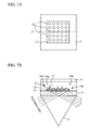
- FIGS. 7A and 7B are enlarged views of the vicinity of a substrate in a third embodiment.
- FIG. 8 is a view showing a schematic constitution of a photometric instrument according to a forth embodiment of the present invention.
- FIG. 9 is a view showing a schematic constitution of a photometric instrument according to a fifth embodiment of the present invention.
- FIG. 10 is a view showing a schematic constitution of a photometric instrument according to a sixth embodiment of the present invention.
- FIG. 11 is a view showing spectral images of structures obtained in the fifth embodiment.
- FIG. 12 is a view showing a schematic constitution of a photometric instrument according to a seventh embodiment of the present invention.
- FIGS. 13A and 13B are enlarged views of the vicinity of a substrate in an eighth embodiment.
- FIG. 14 is a view showing a dispersion image of a substrate obtained in the eighth embodiment
- the present invention relates to an analysis technology for qualitatively detecting, or for quantifying, biomolecules by generating evanescent waves on a surface of a substrate made of a transparent material, then, by means of the evanescent waves, exciting the biomolecules labeled with fluorescent marks in a specimen solution that is supplied on a surface of the substrate, and then detecting fluorescence resultingly emitted from the biomolecules.
- a high S/N ratio can be obtained by long-time exposure because photoluminescence from a metallic structure, and Raman scattering of the solution do not fade away whereas fluorescence from biomolecules fades away within a few minutes.
- a highly accurate spot position standard and a wavelength standard can be obtained as compared to the case where fluorescence from biomolecules is used for the same purpose.
- FIG. 1 is a view showing a schematic constitution of a photometric instrument 100 according to a first embodiment of the present invention.
- excitation light emitted from an excitation source 1 enters a prism 3 and then enters a substrate 4 .
- a space between the prism 3 and the substrate 4 is filled with matching oil, whereby total reflection is prevented from occurring on interfaces of these.
- the excitation light having entered the substrate 4 is totally reflected by an upper surface thereof, and generates evanescent waves on a surface of the substrate.
- a space between the upper surface of the substrate 4 and a cover glass 6 is filled with a reaction solution 5 .
- Luminescence from the surface of the substrate, which is excited by the evanescent waves, is condensed and collimated by an objective lens 7 , and thereafter, a component (elastic scattered light) of the luminescence is eliminated by a luminescence filter 8 , the component having the same wavelengths as the excitation light. Thereafter, the luminescence is dispersed by a dispersing element 9 toward different directions depending on wavelengths, and then, an image is formed on a photoelectric surface of an image sensor 11 by an imaging lens 10 . After undermentioned processing shown in FIG. 5 is executed by a computing unit 20 , the image obtained by the image sensor 11 is recorded on a storage device (HDD) 19 .
- HDD storage device
- a second harmonic wave laser of Nd-YAG whose wavelength is 532 nm is used as the excitation source 1 in this embodiment
- any one of an argon ion laser, a helium neon laser, a semiconductor laser and the like may be used instead.
- the luminescence filter 8 a filter that transmits light having a wavelength of a wavelength of the laser plus ⁇ (for example, 5 nm) can be used, and a long pass filter transmitting light having a wavelength of 540 nm or more is used in this embodiment where the Nd-YAG laser is used.
- any one of a band pass filter transmitting a range of wavelengths to be detected, and a notch filter blocking only a wavelength of the excitation light can be used.
- a prism is used as the dispersing element in this embodiment, it is obvious that a diffraction grating is also acceptable.
- FIGS. 2A and 2B are enlarged views of the vicinity of the substrate 4 of the photometric instrument 100 .
- FIG. 2A is a top view thereof
- FIG. 2B is a cross-sectional view taken along an alternate long and short dash line C.
- a plurality of particulates 12 on which biomolecules 13 are fixed are fixed on the substrate 4 .
- the fixation of the particulates 12 is achieved, for example, by coating the substrate surface with a surfactant and strewing gold particulates thereon.
- gold particulates each having a diameter of 50 nm are used here as the particulates 12
- any metallic particulates made of silver, copper, aluminum, chrome or the like, and each having a diameter not larger than the wavelength of the excitation light are acceptable.
- each of the particulates 12 is not limited to a sphere, and may be any one of a rectangular parallelepiped, a circular cone, a circular cylinder, and another distorted form.
- the gold particulates are randomly strewed in FIG. 2 in order to inexpensively manufacture the substrate, they may be arranged in a lattice pattern.
- the biomolecules 13 fixed on the particulates 12 are single-stranded DNA
- the reaction solution contains fluorescent-labeled bases 14 a , 14 g , 14 c and 14 t , and an enzyme used for causing an extending reaction.
- the base 14 a is adenine labeled with a pigment which becomes luminous by green
- the base 14 g is guanine labeled with a pigment which becomes luminous by orange
- the base 14 c is cytosine labeled with a pigment which becomes luminous by red
- the base 14 t is thymine labeled with a pigment which becomes luminous by infrared.
- FIG. 3 is a view showing a dispersion image of the substrate before the start of the extending reaction.
- FIG. 4 is a view showing dispersion images of the substrate after the extending reaction.
- each of the gold particulates emits broad (meaning that a range of the wavelengths is broad) photoluminescence having wavelengths of 500 to 700 nm, whereby spots of the gold particulates, each of which extends in a laterally long and narrow shape, are obtained.
- a column in the left-hand side of FIG. 4 shows enlarged views of one gold particle spot, and a column in the right-hand side thereof shows graphs describing luminance profiles in lateral directions of the spot.
- (N) corresponds to when there is only a gold particulate
- (A) to when adenine is bonded thereto
- (G) to when guanine is bonded thereto
- T to when thymine is bonded thereto.
- FIG. 5 is a flowchart showing a detailed algorithm of the base species judgment processing.
- a program corresponding to FIG. 5 is stored in an unillustrated memory, and the program is executed by the computing unit 20 when the base species judgment processing is executed. Therefore, a subject who executes processing in each step in FIG. 5 is the computing unit 20 unless otherwise stated.
- Th 1 and Th 2 refer to a predetermined threshold value for judging luminescence of the structures, and a predetermined threshold value for judging luminescence of biomolecules, respectively.
- step S 501 a solution (a buffer) containing neither the fluorescently-labeled bases nor the enzyme is injected between the substrate 4 and the cover glass 6 by an operator. Then, after preparations for acquiring images of luminescence are completed, an instruction for starting observation is inputted to the computing unit 20 by the operator. In this state, only luminescence from the gold particulates is observed.
- a single strand of DNA is previously fixed on each of the structures, and there is a double strand formed therein as a result of partial hybridization of this single strand with another single strand having a sequence complementary to the former single strand.
- step S 502 for example, twenty frames of luminescence images only of a gold particulate are acquired, and the acquired images are averaged with respect to the time axis. Because luminescence of gold does not fade, thus averaging a large number of frames (that is, frames obtained by long-time measurement) makes it possible to obtain a favorable S/N ratio even when the luminescence is weak.
- step S 503 regions each having luminance values of Th 1 or more in at least N laterally consecutive pixels (N>2) are extracted as luminance spots of gold, from an image resulting from the averaging.
- N is set greater than 5 because an apical angle of the prism is adjusted so that luminance wavelengths of gold (550 to 700 nm) can be dispersed in six pixels.
- the number of the extracted regions is denoted by n, and the i-th region thereof and a luminance array thereof are represented by A i and B i , respectively.
- step S 504 the reaction solution (reaction buffer) 5 containing the fluorescently-labeled bases and the enzyme is injected by the operator. Then, after the injection is completed, the instruction for starting observation is inputted to the computing unit 20 by the operator.
- step S 505 variables used in subsequent measurement loop steps S 506 to S 509 are initialized. From this point on, bonding reactions of the bases to the DNA fixed on the gold particulates, and luminescence of phosphors used for labeling begin, and steps S 506 to S 509 are repeated in the meanwhile until the measurement is completed.
- a frame start number j is a number of accumulated frames of images having been serially acquired after the start of the measurement loop.
- a variable k i is a variable for storing a number (frame number) assigned to a frame where luminescence of a phosphor has started by boding of a base to the i-th spot A i .
- a variable l i is a variable for storing a frame number assigned to a frame where the luminescence of the phosphor has ended by removal of the phosphor from the base having bonded to the i-th spot A i .
- step S 506 every time a new frame j is acquired, processing in step S 507 is executed to n regions.
- the processing will be described as processing of the i-th region.
- a difference between a luminance array S i for the region A i in the latest frame and the already recorded luminance array B i also for the region A i with respect to luminescence only of gold has exceeded the predetermined threshold value Th 2 , it is judged that a phosphor, i.e., some base, is bonded to the i-th spot (step S 5071 ), and the processing proceeds to step S 5072 .
- step S 5072 whether k i ⁇ 0 is judged.
- step S 5073 If k i ⁇ 0, it means that the bonding has not yet occurred in a frame before the latest one. Consequently, the bonding starting frame number k i is set to j, for it is judged that new bonding has occurred (step S 5073 ). If k i ⁇ 0, it merely means that a phosphor having bonded in a frame of (j ⁇ 1) or earlier keeps being luminous. Consequently, k i is not changed, and the processing proceeds to the processing for the next spot after i is set to (i+1) (step S 5077 ).
- step S 5071 when a difference between S i and B i is not more than Th 2 , it is judged that a phosphor is not bonded, whereby the processing proceeds to step S 5074 .
- step S 5074 whether k i ⁇ 0 is judged. If k i ⁇ 0, it means that a phosphor has not bonded still since a frame before the latest one. Consequently, the processing proceeds to the processing for the next spot after i is set to (i+1) (step S 5077 ). If k i ⁇ 0, it is judged that a bonded phosphor is removed.
- step S 5075 a difference (which becomes a luminance spectrum of the phosphor) between an average value S i of frames obtained from k i to j, and B i is calculated, whereby a difference d between an index which is a centroid of this array, and a centroid index of B i is found.
- This d represents a central wavelength of the phosphor luminescence spectrum.
- the phosphor used for labeling is judged to be: adenine if ⁇ 3 ⁇ d ⁇ 1; guanine if ⁇ 1 ⁇ d ⁇ 1; cytosine if ⁇ 1 ⁇ d ⁇ 2.5; or thymine if 2.5 ⁇ d ⁇ 4 (step S 5075 ).
- step S 5076 m i is set to (m i +1), and a base corresponding to X[m i ] is stored on the storage device 19 .
- the fluorescent-labeled bases used are nucleotide triphosphate to which phosphors for the labeling is bonded.
- An extending reaction is started with a base coming close to the vicinity of the DNA 13 , and the phosphor exists in the vicinity of the DNA only until the reaction is completed.
- the phosphor is cut off from the base along with phosphate, and is swiftly removed from the vicinity of the DNA 13 by Brownian motion.
- nucleotide triphosphate which is fluorescently labeled with 3′ OH, is extend, and then after the extending reaction, the phosphor is cut off therefrom through a photochemical reaction caused by ultraviolet laser.
- timing for removing a phosphor can be controlled. Additionally, it is also possible that, after a main body of a base of nucleotide triphosphate is labeled with a phosphor, a portion corresponding to the phosphor is cut off through a photochemical reaction caused by ultraviolet laser likewise, or is caused to fade before a next base is incorporated.
- steps S 508 and S 509 are executed for each frame and for all of the spots, and are repeated until m i becomes at least 30 (steps S 508 and S 509 ).
- sequences of at least 30 bases are read for every one of the spots.
- RNA expression analysis of messenger RNA is set as a target application, and a measurement ending condition is set to m i ⁇ 30 as it is sufficient to be able to read 30 bases.
- a measurement ending condition is set to m i ⁇ 30 as it is sufficient to be able to read 30 bases.
- it is only necessary to set the measurement ending condition to a larger numeric value for example, m i ⁇ 100, m i ⁇ 400 or the like.
- the same constitution as that of the photometric instrument 100 according to the first embodiment can be applied to a photometric instrument according to a second embodiment. Therefore, description regarding the constitution of the instrument will be omitted. Additionally, the same processing as that in the first embodiment can be applied to base species judgment here as well.
- FIGS. 6A and 6B are enlarged views of the vicinity of the substrate 4 in the second embodiment.
- FIG. 6A is a top view of the substrate
- FIG. 6B is a cross-sectional view taken along an alternate long and short dash line C in FIG. 6A .
- the structures on which biomolecules are fixed are arranged in a lattice pattern by use of a semiconductor process.
- EB electron beam
- the structures for example, gold particulates
- the structures can be integrated on the substrate 4 with high density, whereby a number of the spots processed at one time can be increased.
- a processing speed for sequencing is improved.
- the same constitution as that of the photometric instrument 100 according to the first embodiment can be applied to a photometric instrument according to a third embodiment. Therefore, description regarding the constitution of the instrument will be omitted. Additionally, the same processing as that in the first embodiment can be applied to base species judgment here as well.
- FIGS. 7A and 7B are enlarged views of the vicinity of the substrate 4 in the third embodiment.
- FIG. 7A is a top view of the substrate
- FIG. 7B is a cross-sectional view taken along an alternate long and short dash line C in FIG. 7A .
- minute apertures provided to a metallic thin film are used as the structures on which biomolecules are fixed.
- Apertures each having a diameter of 100 nm are provided on an aluminum thin film through EB drawing with 2.3 micron pitches in lateral directions and with 1 micron pitches in longitudinal directions.
- a thin film made of any metal such as gold or chrome can be favorably used, and a diameter of each of the apertures can be set to any value not larger than a wavelength (for example, 532 nm in the abovementioned case where the Nd-YAG laser is used) of the excitation light.
- a manufacturing process is not limited to EB drawing, and any one of dry etching and wet etching may be used.
- regions from which evanescent waves are generated are limited to the vicinities of the apertures, and thereby Raman scattering of the reaction solution excited by the evanescent waves occurs only in the vicinities of the apertures (a size of a luminous region is small). Consequently, background light on the substrate 4 is suppressed to be low, and as a result, an S/N ratio of luminescence detection from the phosphors is improved.
- FIG. 8 is a view showing a schematic constitution of a photometric instrument 200 according to a forth embodiment of the present invention. While a basic constitution of the photometric instrument 200 is almost the same as the first embodiment, a band pass filter 15 is insertable into and removable from an optical path by means of a stage 16 . This band pass filter 15 is used to limit luminescence of the structures (for example, gold particulates) to a certain range (a transmission range of the band pass filter) because the luminescence of the structures varies.
- the structures for example, gold particulates
- the band pass filter is inserted into the optical path at the start of the measurement, and is removed therefrom by means of the stage 16 after several frames of images (images only of the structures) are acquired in an inserted state.
- the filter 15 is in a removed state when reactions are caused.
- the fluorescence measurement can be performed also by using a combination of the substrate used in any one of the first to third embodiments and the photometric instrument 200 in this embodiment. Additionally, the same processing as that in the first embodiment can be applied to base species judgment here.
- FIG. 9 is a view showing a schematic constitution of a photometric instrument 300 according to a fifth embodiment of the present invention.
- the photometric instrument 300 is provided with a plurality of excitation sources 1 - 1 and 1 - 2 which respectively output light having different wavelengths, and a constitution of the photometric instrument 300 except these is the same as the first embodiment.
- the fluorescence measurement can be performed also by using a combination of the substrate used in any one of the first to third embodiments and the photometric instrument 300 in this embodiment. Additionally, the same processing as that in the first embodiment can be applied to base species judgment here.
- FIG. 10 is a view showing a schematic constitution of a photometric instrument 400 according to a sixth embodiment of the present invention.
- the photometric instrument 400 is provided with the same constitution as the fifth embodiment with respect to components from at least one excitation source (the excitation sources 1 - 1 and 1 - 2 , or the excitation source 1 - 1 or 1 - 2 ) to the luminescence filter 8 .
- a plurality of dichroic mirrors are used as a means for spectrally separating light the instead of dispersing element 9 . That is, as shown in FIG.
- light having passed through the filter 8 is separated into reflected light and transmitted light by a first dichroic mirror 18 - 1 (which transmits light having a wavelength of 600 nm or more, and reflects light having wavelengths shorter than that). Thereafter, the transmitted light and the reflected light pass through the imaging lens 10 - 1 and the imaging lens 10 - 2 , respectively.
- the reflected light is further separated into reflected light and transmitted light by a second dichroic mirror 18 - 2 (which transmits light having a wavelength of 570 nm or more, and reflects light having wavelengths shorter than that).
- the reflected light here is detected by a first image sensor 11 - 1
- the transmitted light here by a second image sensor 11 - 2 .
- the transmitted light of the first dichroic mirror 18 - 1 is further separated into reflected light and transmitted light by a third dichroic mirror 18 - 3 (which transmits light having a wavelength of 680 nm or more, and reflects light having wavelengths shorter than that).
- the reflected light here is detected by a third image sensor 11 - 3
- the transmitted light here by a fourth image sensor 11 - 4 .
- a substrate which is the same as the substrate used in any one of the first to third embodiments can be used as the substrate 4 in this embodiment.
- FIG. 11 shows examples of spectral images obtained at the same time by the four image sensors 11 - 1 to 11 - 4 . Because the luminescence spectrums of the structures are broad as described above, luminescence spots originating from the same structures can be acquired in every one of these images. Without the structures, it is difficult to identify luminescence from the same biomolecule because bright spots are acquired only in one of the images, and are not acquired in the other images. However, as shown in FIG. 11 , positions in which luminescence spots are to be generated when phosphors have bonded can be found beforehand by the luminescence from the structures. Consequently, it becomes possible to identify luminescence from the same biomolecule with high accuracy, and as a result, possible to perform sequencing with high accuracy.
- a spot in an image does not spread out to be laterally long (refer to FIG. 3 ) because light is not dispersed by a dispersing element. Consequently, overlapping of spots does not occur, and it becomes possible to integrate biomolecules on the substrate with high density. Additionally, it is also possible to perform position alignment by using (1) to (4) of FIG. 11 . Incidentally, the same processing as that in the first embodiment can be applied to base species judgment here.
- FIG. 12 is a view showing a schematic constitution of a photometric instrument 500 according to a seventh embodiment of the present invention.
- elastic scattered light from the substrate 4 is not blocked by the filer 8 , and reflected by a dichroic mirror 18 .
- the reflected light forms an image on the second image sensor 11 - 2 through a second imaging lens 10 - 2 .
- the biomolecules 13 can be more densely integrated on the substrate 4 than in the first embodiment.
- elastic scattered light has a strong intensity. This eliminates the need to use a highly sensitive cooled CCD camera as a second image sensor, and makes it possible to use uncooled CCD, CMOS sensor and the like which are inexpensive. Consequently, a substantial cost increase is not brought about as compared to the first embodiment.
- the same processing as that in the first embodiment can be applied to base species judgment.
- an elastic-scattered-light blocking capability of the filter 8 is lowered.
- dispersion images of photoluminescence of the structures and an image of elastic scattered light are overlapped with one another on the image sensor 11 to form an image thereon.
- this is realized by using only one filter having a light transmittance factor of 1/1000 instead of using two of them as in the case with the first embodiment, or by using a filter having a light transmittance factor of 10 ⁇ 4 to 10 ⁇ 5 .
- FIGS. 13A and 13B show enlarged views of the substrate 4 in the eighth embodiment.
- the structures are integrated with 1 ⁇ m pitches both laterally and longitudinally.
- the structures are thus integrated with 1 ⁇ m pitches on the substrate 4 both laterally and longitudinally, dispersion images of long-wavelength components from the structures are connected with each other, and end up being perceived only as continuous background light.
- this photometric instrument is characterized in that; a wavelength of the light source 1 - 2 is in a transmission range of the filter 8 ; and light outputted by the light source 1 - 2 and then scattered by the structures 12 is detected. Specifically, a HeNe laser of a wavelength of 594 nm is adopted as the light source 1 - 2 . Otherwise, any one of a HeNe laser of a wavelength of 633 nm, and any semiconductor laser can be favorably used.
- the laser of a wavelength of 532 nm which is the same as the light source 1 of the first embodiment, can be used as an light source 1 - 2 , if the transmission range of the filter 8 is changed to 520 nm or more, and if the light source 1 - 1 changed to an argon ion laser of a wavelength of 488 or 514.5 nm. Additionally, a power of the light source 1 - 2 is allowed to be far smaller than that of the light source 1 - 1 , whereby it is also possible to favorably use a light-emitting diode having the wavelength of the transmission range of the filter 8 .
- This embodiment has a characteristic effect that wavelength standard is highly accurate since the scattered light is substantially monochromatic. Additionally, the power of the light source 1 - 2 is allowed to be small, and a cost increase is not substantially brought about as a result of increasing a number of light sources to two.
- the present invention is applied to a DNA sequencer utilizing extending reactions, a DNA microarray reader using a total reflection fluorescence method, and the like.
Abstract
Description
- 1, 1-1, 1-2 excitation source
- 2 excitation filter
- 3 prism
- 4 substrate
- 5 reaction solution
- 6 cover glass
- 7 objective lens
- 8 luminescence filter
- 9 dispersing element
- 10, 10-1, 10-2 imaging lens
- 11, 11-1 to 11-4 image sensor
- 12 structure
- 13 biomolecule
- 14 a adenine
- 14 g guanine
- 14 c cytosine
- 14 t thymine
- 15 band pass filter
- 16 stage
- 18, 18-1 to 18-3 dichroic mirror
- 19 storage device
- 20 computing unit
Claims (19)
Applications Claiming Priority (4)
| Application Number | Priority Date | Filing Date | Title |
|---|---|---|---|
| JP2007-301274 | 2007-11-21 | ||
| JP2007301274 | 2007-11-21 | ||
| JP2008219804A JP5258457B2 (en) | 2007-11-21 | 2008-08-28 | Optical analyzer |
| JP2008-219804 | 2008-08-28 |
Publications (2)
| Publication Number | Publication Date |
|---|---|
| US20090128807A1 US20090128807A1 (en) | 2009-05-21 |
| US8004673B2 true US8004673B2 (en) | 2011-08-23 |
Family
ID=40377100
Family Applications (1)
| Application Number | Title | Priority Date | Filing Date |
|---|---|---|---|
| US12/292,444 Expired - Fee Related US8004673B2 (en) | 2007-11-21 | 2008-11-19 | Photometric instrument |
Country Status (2)
| Country | Link |
|---|---|
| US (1) | US8004673B2 (en) |
| EP (1) | EP2063258A3 (en) |
Families Citing this family (3)
| Publication number | Priority date | Publication date | Assignee | Title |
|---|---|---|---|---|
| US20140125969A1 (en) * | 2012-11-02 | 2014-05-08 | Lawson Health Research Institute | Apparatus and methods for performing optical tomography on dosimeters for calibrating radiotherapy equipment |
| WO2017145230A1 (en) | 2016-02-22 | 2017-08-31 | 株式会社日立ハイテクノロジーズ | Light-emitting detection device |
| DE102018211913B4 (en) * | 2018-07-17 | 2022-10-13 | Carl Zeiss Industrielle Messtechnik Gmbh | Device and method for detecting an object surface using electromagnetic radiation |
Citations (9)
| Publication number | Priority date | Publication date | Assignee | Title |
|---|---|---|---|---|
| JPH09257813A (en) | 1996-03-25 | 1997-10-03 | Kanagawa Kagaku Gijutsu Akad | Probe scanning near-field optical microscope |
| US6180415B1 (en) * | 1997-02-20 | 2001-01-30 | The Regents Of The University Of California | Plasmon resonant particles, methods and apparatus |
| US20050053974A1 (en) | 2003-05-20 | 2005-03-10 | University Of Maryland | Apparatus and methods for surface plasmon-coupled directional emission |
| JP2005070031A (en) | 2003-08-01 | 2005-03-17 | Shimadzu Corp | Component analyzer using microchip |
| US20060170918A1 (en) * | 2005-01-31 | 2006-08-03 | Canon Kabushiki Kaisha | Detection Apparatus and Detection Method for Plasmon Resonance and Fluorescence |
| US20070248991A1 (en) | 2006-04-25 | 2007-10-25 | Canon Kabushiki Kaisha | Base carrier for detecting target substance, element for detecting target substance, method for detecting target substance using the element, and kit for detecting target substance |
| US20080088845A1 (en) * | 2005-01-13 | 2008-04-17 | Clemson University | Surface plasmon induction in multiwalled carbon nanotube arrays |
| US7397559B1 (en) * | 2007-01-23 | 2008-07-08 | Hewlett-Packard Development Company, L.P. | Surface plasmon enhanced Raman spectroscopy |
| US20080278722A1 (en) * | 2007-05-07 | 2008-11-13 | The Board Of Trustees Of The University Of Illinois | Fluorescence detection enhancement using photonic crystal extraction |
Family Cites Families (2)
| Publication number | Priority date | Publication date | Assignee | Title |
|---|---|---|---|---|
| JP2007301274A (en) | 2006-05-15 | 2007-11-22 | Pentax Corp | Infrared ray-cutting filter furnished endoscope device |
| JP2008219804A (en) | 2007-03-07 | 2008-09-18 | Fujifilm Corp | Photographing system and photographing apparatus inspecting method |
-
2008
- 2008-11-19 US US12/292,444 patent/US8004673B2/en not_active Expired - Fee Related
- 2008-11-20 EP EP08020249A patent/EP2063258A3/en not_active Withdrawn
Patent Citations (9)
| Publication number | Priority date | Publication date | Assignee | Title |
|---|---|---|---|---|
| JPH09257813A (en) | 1996-03-25 | 1997-10-03 | Kanagawa Kagaku Gijutsu Akad | Probe scanning near-field optical microscope |
| US6180415B1 (en) * | 1997-02-20 | 2001-01-30 | The Regents Of The University Of California | Plasmon resonant particles, methods and apparatus |
| US20050053974A1 (en) | 2003-05-20 | 2005-03-10 | University Of Maryland | Apparatus and methods for surface plasmon-coupled directional emission |
| JP2005070031A (en) | 2003-08-01 | 2005-03-17 | Shimadzu Corp | Component analyzer using microchip |
| US20080088845A1 (en) * | 2005-01-13 | 2008-04-17 | Clemson University | Surface plasmon induction in multiwalled carbon nanotube arrays |
| US20060170918A1 (en) * | 2005-01-31 | 2006-08-03 | Canon Kabushiki Kaisha | Detection Apparatus and Detection Method for Plasmon Resonance and Fluorescence |
| US20070248991A1 (en) | 2006-04-25 | 2007-10-25 | Canon Kabushiki Kaisha | Base carrier for detecting target substance, element for detecting target substance, method for detecting target substance using the element, and kit for detecting target substance |
| US7397559B1 (en) * | 2007-01-23 | 2008-07-08 | Hewlett-Packard Development Company, L.P. | Surface plasmon enhanced Raman spectroscopy |
| US20080278722A1 (en) * | 2007-05-07 | 2008-11-13 | The Board Of Trustees Of The University Of Illinois | Fluorescence detection enhancement using photonic crystal extraction |
Non-Patent Citations (2)
| Title |
|---|
| European Search Report for corresponding European Patent Application No. 08020249.2-2217/2063258. |
| Takashi Funatsu et al., Imaging of Single Fluorescent Moleculres and individual ATP Turnovers by Single Myosin Molecules in Aqueous Solution:, Letters of Nature, vol. 374, Apr. 6, 1995, pp. 555-559. |
Also Published As
| Publication number | Publication date |
|---|---|
| US20090128807A1 (en) | 2009-05-21 |
| EP2063258A3 (en) | 2010-12-01 |
| EP2063258A2 (en) | 2009-05-27 |
Similar Documents
| Publication | Publication Date | Title |
|---|---|---|
| JP5337676B2 (en) | Fluorescence analyzer and fluorescence detector | |
| US20170058343A1 (en) | Systems and methods for color detection in high-throughput nucleic acid sequencing systems | |
| US8263956B2 (en) | Optical flow channel measuring instrument | |
| WO2010146758A1 (en) | Fluorescent analysis method | |
| JP6581707B2 (en) | Nucleic acid analyzer and nucleic acid analysis method | |
| US8680483B2 (en) | Fluorescence detector | |
| JP2009526997A (en) | Method and system for simultaneously monitoring optical signals from multiple sources in real time | |
| KR20130138214A (en) | Defect inspection and photoluminescence measurement system | |
| CN115266662A (en) | Hyperspectral sequencing method and system and gene sequencer | |
| US8004673B2 (en) | Photometric instrument | |
| WO2015053144A1 (en) | Nucleic-acid-sequence determination device and nucleic-acid-sequence determination method | |
| JP6416530B2 (en) | Fluorescence observation apparatus and fluorescence observation method | |
| JP5258457B2 (en) | Optical analyzer | |
| US8389959B2 (en) | Fluorescence analyzing device and fluorescence analyzing method | |
| US7154602B2 (en) | Method for measuring fluorescence correlations in the presence of slow signal fluctuations | |
| US20100091287A1 (en) | Method for Imaging a Sample Using a Microscope, and Microscope and Data Storage Center | |
| KR100483706B1 (en) | A Apparatus for the Detection of Laser-induced Epifluoresecne | |
| KR20070045720A (en) | Multiple channel bio chip scanner | |
| JP2012023988A (en) | Method for nucleic acid analysis, apparatus for implementing the method, and reagent set for nucleic acid analysis | |
| US20130157264A1 (en) | Nucleic acid analysis device, nucleic acid analysis apparatus, and nucleic acid analysis method | |
| WO2021070259A1 (en) | Analysis device and analysis method | |
| JP5581228B2 (en) | Fluorescence detection device | |
| US11549887B2 (en) | Method for analyzing digital PCR data using multicolor fluorescence reader | |
| JP2011002398A (en) | Spectroscopic imaging device | |
| JP2004013128A (en) | Fluorescence microscope |
Legal Events
| Date | Code | Title | Description |
|---|---|---|---|
| AS | Assignment |
Owner name: HITACHI HIGH-TECHNOLOGIES CORPORATION, JAPAN Free format text: ASSIGNMENT OF ASSIGNORS INTEREST;ASSIGNORS:SONEHARA, TSUYOSHI;TAKAHASHI, SATOSHI;SAKAI, TOMOYUKI;REEL/FRAME:021917/0937;SIGNING DATES FROM 20081030 TO 20081031 Owner name: HITACHI HIGH-TECHNOLOGIES CORPORATION, JAPAN Free format text: ASSIGNMENT OF ASSIGNORS INTEREST;ASSIGNORS:SONEHARA, TSUYOSHI;TAKAHASHI, SATOSHI;SAKAI, TOMOYUKI;SIGNING DATES FROM 20081030 TO 20081031;REEL/FRAME:021917/0937 |
|
| STCF | Information on status: patent grant |
Free format text: PATENTED CASE |
|
| FEPP | Fee payment procedure |
Free format text: PAYER NUMBER DE-ASSIGNED (ORIGINAL EVENT CODE: RMPN); ENTITY STATUS OF PATENT OWNER: LARGE ENTITY Free format text: PAYOR NUMBER ASSIGNED (ORIGINAL EVENT CODE: ASPN); ENTITY STATUS OF PATENT OWNER: LARGE ENTITY |
|
| FPAY | Fee payment |
Year of fee payment: 4 |
|
| FEPP | Fee payment procedure |
Free format text: MAINTENANCE FEE REMINDER MAILED (ORIGINAL EVENT CODE: REM.); ENTITY STATUS OF PATENT OWNER: LARGE ENTITY |
|
| LAPS | Lapse for failure to pay maintenance fees |
Free format text: PATENT EXPIRED FOR FAILURE TO PAY MAINTENANCE FEES (ORIGINAL EVENT CODE: EXP.); ENTITY STATUS OF PATENT OWNER: LARGE ENTITY |
|
| STCH | Information on status: patent discontinuation |
Free format text: PATENT EXPIRED DUE TO NONPAYMENT OF MAINTENANCE FEES UNDER 37 CFR 1.362 |
|
| FP | Lapsed due to failure to pay maintenance fee |
Effective date: 20190823 |