US8005407B2 - Developer apparatus with restriction member that restricts thickness of toner layer on toner carrier roller - Google Patents
Developer apparatus with restriction member that restricts thickness of toner layer on toner carrier roller Download PDFInfo
- Publication number
- US8005407B2 US8005407B2 US12/254,646 US25464608A US8005407B2 US 8005407 B2 US8005407 B2 US 8005407B2 US 25464608 A US25464608 A US 25464608A US 8005407 B2 US8005407 B2 US 8005407B2
- Authority
- US
- United States
- Prior art keywords
- toner
- carrier roller
- convex sections
- restriction
- toner carrier
- Prior art date
- Legal status (The legal status is an assumption and is not a legal conclusion. Google has not performed a legal analysis and makes no representation as to the accuracy of the status listed.)
- Expired - Fee Related, expires
Links
Images


Classifications
-
- G—PHYSICS
- G03—PHOTOGRAPHY; CINEMATOGRAPHY; ANALOGOUS TECHNIQUES USING WAVES OTHER THAN OPTICAL WAVES; ELECTROGRAPHY; HOLOGRAPHY
- G03G—ELECTROGRAPHY; ELECTROPHOTOGRAPHY; MAGNETOGRAPHY
- G03G15/00—Apparatus for electrographic processes using a charge pattern
- G03G15/06—Apparatus for electrographic processes using a charge pattern for developing
- G03G15/08—Apparatus for electrographic processes using a charge pattern for developing using a solid developer, e.g. powder developer
- G03G15/0806—Apparatus for electrographic processes using a charge pattern for developing using a solid developer, e.g. powder developer on a donor element, e.g. belt, roller
- G03G15/0812—Apparatus for electrographic processes using a charge pattern for developing using a solid developer, e.g. powder developer on a donor element, e.g. belt, roller characterised by the developer regulating means, e.g. structure of doctor blade
-
- G—PHYSICS
- G03—PHOTOGRAPHY; CINEMATOGRAPHY; ANALOGOUS TECHNIQUES USING WAVES OTHER THAN OPTICAL WAVES; ELECTROGRAPHY; HOLOGRAPHY
- G03G—ELECTROGRAPHY; ELECTROPHOTOGRAPHY; MAGNETOGRAPHY
- G03G15/00—Apparatus for electrographic processes using a charge pattern
- G03G15/06—Apparatus for electrographic processes using a charge pattern for developing
- G03G15/08—Apparatus for electrographic processes using a charge pattern for developing using a solid developer, e.g. powder developer
- G03G15/0806—Apparatus for electrographic processes using a charge pattern for developing using a solid developer, e.g. powder developer on a donor element, e.g. belt, roller
- G03G15/0818—Apparatus for electrographic processes using a charge pattern for developing using a solid developer, e.g. powder developer on a donor element, e.g. belt, roller characterised by the structure of the donor member, e.g. surface properties
-
- G—PHYSICS
- G03—PHOTOGRAPHY; CINEMATOGRAPHY; ANALOGOUS TECHNIQUES USING WAVES OTHER THAN OPTICAL WAVES; ELECTROGRAPHY; HOLOGRAPHY
- G03G—ELECTROGRAPHY; ELECTROPHOTOGRAPHY; MAGNETOGRAPHY
- G03G2215/00—Apparatus for electrophotographic processes
- G03G2215/01—Apparatus for electrophotographic processes for producing multicoloured copies
- G03G2215/0167—Apparatus for electrophotographic processes for producing multicoloured copies single electrographic recording member
- G03G2215/0174—Apparatus for electrophotographic processes for producing multicoloured copies single electrographic recording member plural rotations of recording member to produce multicoloured copy
- G03G2215/0177—Rotating set of developing units
Definitions
- the present invention relates to a developer apparatus which comprises a toner carrier roller which carries toner on a surface thereof, an image forming apparatus and a developing method of developing an electrostatic latent image with toner using this roller.
- Techniques for developing an electrostatic latent image with toner include an apparatus which causes a surface of a toner carrier roller to carry toner, the toner carrier roller being shaped approximately like a cylinder.
- the applicant of the present application has earlier disclosed a structure of a toner carrier roller having a cylindrical shape that the surface of the roller includes convex sections which are regularly arranged and a concave section which surrounds the convex sections (JP-A-2007-127800). Since the concavo-convex patterns in the surface are regulated and uniform, such a structure is advantageous in that it permits easy control of the thickness of a toner layer which is carried on the surface of the roller, the charge level and the like.
- a toner carrier roller having the structure above for the purpose of preventing toner carried by the convex sections from getting deteriorated due to friction contact with a restriction member and the like which regulates a thickness of a toner layer, only the concave section may carry toner.
- toner carried by the concave section is free from friction contact with or pressing force from the restriction member.
- toner hardly deteriorates, which makes it possible to retain initial toner characteristics for a long period of time.
- development is performed with toner which is not under pressing force. Therefore, it is possible to prevent excessive charging of toner and to improve an image quality by improving efficiency of development, suppressing a memory phenomenon after formation of a high-density image, and the like.
- An advantage of some aspects of the invention is to provide a technique for prevention of both toner degradation and discharge in a developer apparatus, an image forming apparatus and a developing method which use a toner carrier roller which is provided with concavo-convex on its surface.
- a developer apparatus comprising: a container which houses toner; a toner carrier roller that is provided, on a surface thereof, with a plurality of convex sections which are regularly arranged and a concave section which surrounds the convex sections, is shaped approximately like a cylinder, and rotates while carrying a toner layer of charged toner on the surface thereof; and a restriction member that abuts on the surface of the toner carrier roller to form a restriction nip, restricts a thickness of the toner layer carried on the surface of the toner carrier roller in the restriction nip, and removes the toner layer on the convex sections from among the toner layer carried on the surface of the toner carrier roller at an upstream-side end of the restriction nip in a rotation direction of the toner carrier roller, wherein a part of toner carried by the concave section moves to the convex sections to cover the convex sections with the toner at a downstream side
- an image forming apparatus comprising: an image carrier that carries an electrostatic latent image; a developer that includes a toner carrier roller and a restriction member, the toner carrier roller being provided, on a surface thereof, with a plurality of convex sections which are regularly arranged and a concave section which surrounds the convex sections, being made of a conductive material, being shaped approximately like a cylinder, and rotating while carrying a toner layer of charged toner on the surface thereof to transport the toner layer to an opposed position against the image carrier, the restriction member abutting on the surface of the toner carrier roller to form a restriction nip, and restricting a thickness of the toner layer carried on the surface of the toner carrier roller in the restriction nip; and a bias applier that applies a predetermined developing bias to the toner carrier roller to develop the electrostatic latent image carried on the image carrier with the toner, wherein toner is not carried on the convex sections within
- a developing method comprising: rotating a toner carrier roller that is provided, on a surface thereof with a plurality of convex sections which are regularly arranged and a concave section which surrounds the convex sections, is shaped approximately like a cylinder, and carries a toner layer of charged toner on the surface thereof to transport the toner layer to an opposed position against an image carrier which carries an electrostatic latent image; developing the electrostatic latent image with the toner; preventing the convex sections within the surface of the toner carrier roller from carrying toner at an upstream-side end of the restriction nip in a rotation direction of the toner carrier roller; and covering the convex sections with toner which has been carried on the concave section and has partially moved to the convex sections at a downstream side to the restriction nip and at an upstream side to the opposed position against the image carrier in the rotation direction of the toner carrier roller.
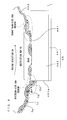
- FIG. 1 is a diagram showing a first embodiment of an image forming apparatus according to the invention.
- FIG. 2 is a block diagram of an electric structure of the image forming apparatus which is shown in FIG. 1 .
- FIG. 3 is a diagram showing the appearance of the developer.
- FIG. 4A is a cross sectional view showing a structure of the developer.
- FIG. 4B is a graph showing the relationship between a waveform of a developing bias and a surface potential of the photosensitive member.
- FIG. 5 is a group of diagrams showing a side view of the developing roller and a partially expanded view of the surface of the developing roller.
- FIGS. 6A and 6B are diagrams describing the relationship between a toner layer and a discharge in the developing gap.
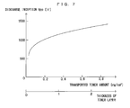
- FIG. 7 is a graph showing the relationship between the transported toner amount and the discharge inception voltage.
- FIGS. 8A and 8B are diagrams showing a condition of the developing roller and the restriction blade abutting on each other.
- FIG. 9 is an enlarged schematic view of the restriction nip.
- FIGS. 10A and 10B are diagrams showing a structure of a modified embodiment to enhance the effect of discharge prevention.
- FIG. 11 is an enlarged diagram schematically showing the restriction nip in this modified embodiment.
- FIGS. 12A and 12B are diagrams showing image forming apparatuses of a second and a third embodiments according to the invention, respectively.
- FIGS. 13A to 13C are diagrams schematically showing a condition of movement of toner to the convex sections in the second and the third embodiments.
- FIGS. 14A and 14B are graphs showing cross sectional profiles of the developing roller after the developing roller has moved past the restriction nip.
- FIGS. 15A and 15B are diagrams schematically showing the relationship between a height difference on the surface of the developing roller and toner carried on the surface of the developing roller.
- FIG. 16 is a graph showing the relationship between the particle diameter of toner and adhesion force to the developing roller.
- FIG. 17 is a graph showing the relationship between the particle diameter of toner and a charge level to start the development.
- FIG. 1 is a diagram showing a first embodiment of an image forming apparatus according to the invention.
- FIG. 2 is a block diagram of an electric structure of the image forming apparatus which is shown in FIG. 1 .
- This apparatus is an image forming apparatus which overlays toner in four colors of yellow (Y), cyan (C), magenta (M) and black (K) one atop the other and accordingly forms a full-color image, or forms a monochrome image using only black toner (K).
- a CPU 101 provided in an engine controller 10 controls respective portions of an engine part EG in accordance with an instruction received from the main controller 11 to perform a predetermined image forming operation, and accordingly, an image which corresponds to the image signal is formed on a sheet S.
- a photosensitive member 22 is disposed so that the photosensitive member 22 can freely rotate in an arrow direction D 1 shown in FIG. 1 .
- a charger unit 23 Around the photosensitive member 22 , a charger unit 23 , a rotary developer unit 4 and a cleaner 25 are disposed in the rotation direction D 1 .
- a predetermined charging bias is applied upon the charger unit 23 , whereby an outer circumferential surface of the photosensitive member 22 is charged uniformly to a predetermined surface potential.
- the cleaner 25 removes toner which remains adhering to the surface of the photosensitive member 22 after primary transfer, and collects the toner into a waste toner tank which is disposed inside the cleaner 25 .
- the photosensitive member 22 , the charger unit 23 and the cleaner 25 integrated as one, form a photosensitive member cartridge 2 .
- the photosensitive member cartridge 2 can be freely attached to and detached from an apparatus main body as one integrated unit.
- An exposure unit 6 emits a light beam L toward the outer circumferential surface of the photosensitive member 22 charged by the charger unit 23 .
- This exposure unit 6 exposes the photosensitive member 22 by the light beam L in accordance with the image signal given from the external apparatus to form an electrostatic latent image corresponding to the image signal.
- the developer unit 4 develops thus formed electrostatic latent image with toner.
- the developer unit 4 includes a support frame 40 which is provided rotatable about a rotation shaft orthogonal to a plane of FIG. 1 and a yellow developer 4 Y, a cyan developer 4 C, a magenta developer 4 M and a black developer 4 K which are freely attachable to and detachable from the support frame 40 and house toner of the respective colors.
- An engine controller 10 controls the developer unit 4 .
- the developer unit 4 is driven into rotation based on a control instruction from the engine controller 10 .
- the developing roller 44 which is disposed in this developer and carries a toner of a selected color is positioned facing the photosensitive member 22 , and the developing roller 44 supplies the toner onto the surface of the photosensitive member 22 at the facing position. As a result, the electrostatic latent image on the photosensitive member 22 is visualized with the toner of the selected color.
- FIG. 3 is a diagram showing the appearance of the developer.
- FIG. 4A is a cross sectional view showing a structure of the developer
- FIG. 4B is a graph showing the relationship between a waveform of a developing bias and a surface potential of the photosensitive member.
- the developers 4 Y, 4 C, 4 M and 4 K have identical structures. Therefore, the structure of the developer 4 K will now be described in further detail with reference to FIGS. 3 and 4A .
- the other developers 4 Y, 4 C and 4 M have the same structures and functions, to be noted.
- a feed roller 43 and a developing roller 44 are rotatably attached with a shaft to a housing 41 which houses monocomponent toner T inside.
- the developing roller 44 is positioned at a facing position which is faced with the photosensitive member 22 over a developing gap DG, and these rollers 43 and 44 are engaged with a rotation driver (not shown) which is provided in the main body to rotate in a predetermined direction.
- the feed roller 43 is shaped like a cylinder and is made of an elastic material such as foamed urethane rubber and silicone rubber.
- the developing roller 44 is shaped like a cylinder and is made of metal or alloy such as copper, aluminum and stainless steel.
- the two rollers 43 and 44 rotate while staying in contact with each other, and accordingly, the toner is rubbed against the surface of the developing roller 44 and a toner layer having a predetermined thickness is formed on the surface of the developing roller 44 .
- negatively-charged toner is used in this embodiment, positively-charged toner may be used instead.
- the space inside the housing 41 is divided by a partition wall 41 a into a first chamber 411 and a second chamber 412 .
- the feed roller 43 and the developing roller 44 are both provided in the second chamber 412 . With a rotation of these rollers, toner within the second chamber 412 flows and is fed to the surface of the developing roller 44 while getting agitated. Meanwhile toner stored inside the first chamber 411 would not be moved by the rotation since it is isolated from the feed roller 43 and the developing roller 44 . This toner is mixed with toner stored in the second chamber 412 and is agitated by the rotation of the developer unit 4 while holding the developer.
- the inside of the housing is separated into the two chambers, and the side walls of the housing 41 and the partition wall 41 a surround the feed roller 43 and the developing roller 44 , and accordingly, the second chamber 412 of relatively small volume is provided. Therefore, even when a remaining toner amount is small, toner is supplied efficiently to near the developing roller 44 . Further, supply of toner from the first chamber 411 to the second chamber 412 and agitation of the whole toner are performed by the rotation of the developer unit 4 . Hence, an auger-less structure is realized that an agitator member (auger) for agitating toner is not provided inside the developer.
- a restriction blade 46 is disposed which restricts the thickness of the toner layer formed on the surface of the developing roller 44 into the predetermined thickness.
- the restriction blade 46 includes a plate-like member 461 made of elastic material such as stainless steel, phosphor bronze or the like and an elastic member 462 which is attached to a front edge of the plate-like member 461 and is made of a resin member such as silicone rubber and a urethane rubber. A rear edge of the plate-like member 461 is fixed to the housing 41 .
- the elastic member 462 attached to the front edge of the plate-like member 461 is positioned on the upstream side to the rear edge of the plate-like member 461 in a rotation direction D 4 of the developing roller 44 shown by an arrow in FIG. 4 .
- the elastic member 462 elastically abuts on the surface of the developing roller 44 to form a restriction nip, thereby restricting the toner layer formed on the surface of the developing roller 44 finally into the predetermined thickness.
- the toner layers thus formed on the surface of the developing roller 44 are transported, by means of the rotation of the developing roller 44 , one after another to the opposed positions against the photosensitive member 22 on the surface of which an electrostatic latent image is formed.
- the developing bias from a bias power source 140 controlled by the engine controller 10 is applied to the developing roller 44 .
- a surface potential Vs of the photosensitive member 22 drops down approximately to a residual potential Vr at exposed segments exposed by the light beam L from the exposure unit 6 after getting uniformly charged by the charger unit 23 , but stays at an almost uniform potential V 0 at non-exposed segments not exposed by the light beam L.
- the developing bias Vb applied to the developing roller 44 is rectangular-wave AC voltage on which a DC potential Vave is superimposed, and its peak-to-peak voltage will be hereinafter denoted at Vpp.
- Vpp peak-to-peak voltage
- toner carried on the developing roller 44 is made jump across a developing gap DG and partially adheres to the respective sections in the surface of the photosensitive member 22 in accordance with the surface potential Vs of the photosensitive member 22 , whereby an electrostatic latent image on the photosensitive member 22 is visualized as a toner image in the color of the toner.
- the housing 41 further includes a seal member 47 which is pressed against the surface of the developing roller 44 on the downstream side to the opposed position facing the photosensitive member 22 in the rotation direction of the developing roller 44 .
- the seal member 47 guides toner which remains on the surface of the developing roller 44 after moving past the opposed position facing the photosensitive member 22 to inside the housing 41 and prevents toner inside the housing from leaking to outside.
- FIG. 5 is a group of diagrams showing a side view of the developing roller and a partially expanded view of the surface of the developing roller.
- the developing roller 44 is shaped like an approximately cylindrical roller.
- a shaft 440 is provided at the both ends of the roller in the longitudinal direction of the roller such that the shaft is coaxial with the roller. With the shaft 440 supported by the developer main body, the entire developing roller 44 is freely rotatable
- a central area 44 a in the surface of the developing roller 44 is provided with a plurality of convex sections 441 which are regularly arranged and a concave section 442 which surrounds the convex sections 441 .
- Each one of the convex sections 441 projects forward from the plane of FIG. 5 , and a top surface of each convex section 441 forms a part of a single cylindrical surface which is coaxial with a rotation shaft of the developing roller 44 .
- the concave section 442 is a continuous groove which surrounds the convex sections 441 like a net.
- the entire concave section 442 also forms a single cylindrical surface which is different from the cylindrical surface which is made by the convex sections and is coaxial with the rotation shaft of the developing roller 44 .
- the developing roller 44 having such a structure may be made by the manufacturing method described in JP-A-2007-140080 for instance.
- each convex section 441 and a distance L 2 between the respective convex sections are preferably larger than a particle diameter of toner and may be but are not limited to 10 through 100 ⁇ m approximately for instance.
- the shape, the arrangement and the like of the convex sections 441 are not limited to those described here. A difference in height between the convex sections 441 and the concave section 442 will be described later.
- the toner image developed by the developer unit 4 as described above is primarily transferred onto an intermediate transfer belt 71 of a transfer unit 7 in a primary transfer region TR 1 .
- the transfer unit 7 includes the intermediate transfer belt 71 mounted on a plurality of rollers 72 to 75 and a driver (not shown) for driving the roller 73 into rotation to rotate the intermediate transfer belt 71 in a specified rotating direction D 2 .
- the toner images of the respective colors formed on the photosensitive member 22 are superimposed on the intermediate transfer belt 71 to form the color image, which is secondarily transferred onto the sheet S dispensed one by one from a cassette 8 and conveyed to a secondary transfer region TR 2 along a conveyance path F.
- the timing of feeding the sheet S into the secondary transfer region TR 2 is controlled.
- the sheet S on which the color image is thus formed is transported to a discharge tray 89 which is disposed at a top surface of the apparatus main body via a pre-discharge roller 82 and a discharge roller 83 after the toner image is fixed to the sheet S by a fixing unit 9 .
- the discharge roller 83 starts rotating in the reverse direction upon arrival of the rear end of the sheet S, which carries the image on its one surface as described above, at a reversing position PR located behind the pre-discharge roller 82 , thereby transporting the sheet S in the arrow direction D 3 along a reverse transportation path FR.
- the sheet S is returned back to the transportation path F again before arriving at the gate roller 81 .
- the surface of the sheet S which abuts on the intermediate transfer belt 71 in the secondary transfer region TR 2 and is to receive a transferred image is opposite to the surface which already carries the image. In this fashion, it is possible to form images on the both surfaces of the sheet S.
- the respective developers 4 Y, 4 C, 4 M and 4 K comprise memories 91 , 92 , 93 and 94 respectively which store data related to the production lot, the use history, the remaining toner amount and the like of the developers.
- wireless telecommunication devices 49 Y, 49 C, 49 M and 49 K are provided in the developers 4 Y, 4 C, 4 M and 4 K, respectively.
- the telecommunication devices selectively perform non-contact data telecommunication with a wireless telecommunication device 109 which is provided in the apparatus main body, whereby data transmission between the CPU 101 and the memories 91 through 94 via the interface 105 is performed to manage various types of information regarding the developers such as management of consumables.
- non-contact data transmission using electromagnetic scheme such as wireless telecommunication is performed.
- the apparatus main body and each developer may be provided with connectors and the like, and the connectors may be engaged mechanically to perform data transmission between each other.
- the apparatus includes a display 12 which is controlled by a CPU 111 of the main controller 11 .
- the display 12 is formed by a liquid crystal display for instance, and shows predetermined messages which are indicative of operation guidance for a user, a progress in the image forming operation, abnormality in the apparatus, the timing of exchanging any one of the units, and the like in accordance with the control command from the CPU 111 .
- a reference numeral 113 represents an image memory provided in the main controller 11 in order to store the image supplied from the external apparatus, such as a host computer, via the interface 112 .
- a reference numeral 106 represents a ROM for storage of an operation program executed by the CPU 101 and control data used for controlling the engine EG.
- a reference numeral 107 represents a RAM for temporary storage of operation results given by the CPU 101 and other data.
- a cleaner 76 in the vicinity of the roller 75 .
- the cleaner 76 moves nearer to and away from the roller 75 driven by an electromagnetic clutch not shown.
- a blade of the cleaner 76 abuts on the surface of the intermediate transfer belt 71 mounted on the roller 75 and scrapes off the toner remaining on and adhering to the outer circumferential surface of the intermediate transfer belt 71 after the secondary transfer.
- a density sensor 60 is disposed in the vicinity of the roller 75 .
- the density sensor 60 confronts a surface of the intermediate transfer belt 71 and measures, as needed, the density of the toner image formed on the outer circumferential surface of the intermediate transfer belt 71 .
- the apparatus adjusts the operating conditions of the individual parts thereof that affects the image quality such as a developing bias applied to each developer, the intensity of the exposure beam L, and tone-correction characteristics of the apparatus, for example.
- the density sensor 60 is structured to output a signal corresponding to a contrasting density of a region of a predetermined area defined on the intermediate transfer belt 71 using a reflective optical sensor, for example.
- the CPU 101 is adapted to detect image densities of individual parts of the toner image on the intermediate transfer belt 71 by periodically sampling the output signals from the density sensor 60 while moving the intermediate transfer belt 71 in rotation.
- the distance between the restriction blade 46 and the convex sections 441 needs be controlled precisely in order to form a uniform toner layer on the convex sections 441 .
- the restriction blade 46 may abut on the convex sections 441 and remove all toner on the convex sections 441 , which can be realized relatively easily.
- the volume of the space defined between the restriction blade 46 and the concave section 442 determines the amount of transported toner, it is possible to stabilize a transported toner amount.
- This provides another advantage with respect to superiority of a transported toner layer. That is, carrying of toner by the convex sections 441 tends to degrade toner because of friction contact of the toner with the restriction blade 46 . More specifically, there are problems such as reduction of the fluidity and the charging performance of toner, clumping together due to toner particles pressed to each other, and filming due to fixedly adherence of toner to the developing roller 44 . In contrast, carrying of toner by the concave section 442 which is less influenced by the pressure from the restriction blade 46 is less likely to give rise to such problems. Further, the manner of friction contact on the restriction blade 46 is greatly different between toner carried by the convex sections 441 and toner carried by the concave section 442 . Hence, their charge levels are predicted to largely vary from each other. However, carrying of toner by the concave section 442 alone makes it possible to suppress such variations.
- the structure in this embodiment meets the demand.
- Small-particle toner generally has a high saturation charge level but gets charged slowly at the beginning, and hence, of toner carried by the convex sections 441 , a portion which has not contributed to previous development has an increased charge level.
- new toner held inside the developer is fed onto the developing roller 44 in a part which carried toner that has contributed to previous development. However, since the new toner is charged up slowly at the beginning, its charge level will not immediately reach the charge level of the other part of toner.
- the presence of segments having different toner charge levels on the developing roller 44 leads to local image density variations (the development history, the memory phenomenon), density variations corresponding to the rotation cycle of the developing roller 44 during formation of a solid image for instance.
- the workload is increased through adjustment of the rotation frequency and the pressure force of the feed roller 43 and the reset performance of the feed roller 43 is enhanced, and accordingly, such a phenomenon is beginning to be improved.
- this causes different problems that the drive torque of the developing roller 44 increases and toner degrades faster.
- toner having a low melting point fixing of toner to each other and fixing of the toner to the developing roller 44 and the like could occur by the friction contact of toner with each other and with the developing roller 44 .
- such a problem is less likely to occur where the structure according to the embodiment is used in which only the concave section 442 carries toner.
- FIGS. 6A and 6B are diagrams describing the relationship between a toner layer and a discharge in the developing gap.
- the concave section 442 alone carries toner but the convex sections 441 do not carry toner as shown in FIG. 6A .
- this exposes the convex sections 441 , which are portions of the metallic developing roller 44 , to the surface 22 a of the photosensitive member 22 within the developing gap DG, and causes discharge in the developing gap DG depending upon which one of the developing bias Vb and the surface potential Vs of the photosensitive member is larger than the other.
- a toner layer on the surface of the developing roller, serving as a dielectric layer has an effect to suppress discharge and that a condition of toner covering the surface of the developing roller is an important factor for prevention of discharge.
- Reduction of the developing bias Vb, and more particularly, its peak-to-peak voltage Vpp is effective for prevention of discharge.
- a lower developing bias makes it harder for toner to jump across the developing gap DG, and accordingly, the density, the quality and the like of an image are reduced.
- Other method to prevent discharge is to cover the entire surface of the developing roller 44 with toner T as shown in FIG. 6B .
- FIG. 7 is a graph showing the relationship between the transported toner amount and the discharge inception voltage. Describing this in more detail, FIG. 7 is a graph showing how much increase of the peak-to-peak voltage Vpp of the developing bias Vb initiates discharge with a transported toner amount per unit area of the surface of the developing roller 44 set to various values.
- the minimum value of the voltage Vpp which gives rise to discharge in response to each value of the transported toner amount is called “discharge inception Vpp” for each transported toner amount.
- the smaller the transported toner amount is on the surface of the developing roller 44 the lower the discharge inception Vpp is, and further, the discharge inception Vpp sharply decreases in a region where the transported toner amount is small.
- the discharge inception Vpp sharply decreases in the case where the toner layer on the surface of the developing roller is less than one toner layer and the surface gets partially exposed. This shows that coating of the surface of the metallic developing roller 44 with toner which is an insulator makes it possible to increase the discharge inception Vpp and to suppress discharge within the developing gap DG.
- the convex sections 441 do not carry toner to ensure a favorable toner layer carried on the developing roller 44 .
- the convex sections 441 there is a contradicting demand that the convex sections 441 as well should carry toner for prevention of discharge. These demands however can be satisfied simultaneously. It is within the restriction nip that the convex sections 441 should not carry toner. Meanwhile, it is within the developing gap DG which is located on the downstream side to the restriction nip in the rotation direction D 4 of the developing roller 44 that the convex sections 441 should carry toner.
- toner may be made adhere to the convex sections 441 to coat the convex sections 441 before the convex sections 441 arrive at the developing gap DG.
- toner which is made adhere to the convex sections 441 is toner carried by the surface of the developing roller 44 which has moved past the restriction nip, namely, toner carried by the concave section 442 .
- toner carried by the concave section 442 which has moved past the restriction nip is made move to the convex sections 441 in the following manner.
- FIGS. 8A and 8B are diagrams showing a condition of the developing roller and the restriction blade abutting on each other.
- the restriction blade 46 abuts on the surface of the developing roller 44 in a direction against the rotation direction D 4 of the developing roller 44 .
- the elastic member 462 at the tip end of the restriction blade 46 gets pressed by the surface of the developing roller 44 and partially and elastically deformed, whereby a restriction nip N 1 is formed in which the surface of the developing roller 44 contacts the elastic member 462 .
- an upper edge of an upstream-side end 462 a of the elastic member 462 in the rotation direction D 4 of the developing roller 44 is within the restriction nip N 1 , and toner is regulated by means of the edge restriction.
- the upstream-side end 462 a of the elastic member 462 is located on the upstream side in the rotation direction D 4 of the developing roller 44 relative to a perpendicular from the rotation center of the developing roller 44 to the top surface of the elastic member 462 .
- the deformation Db of the elastic member 462 owing to elastic deformation in the vicinity of the upstream-side end 462 a is somewhat smaller than the maximum deformation Da of the elastic member 462 in the vicinity of the foot of the perpendicular.
- the elastic member 462 positioned like this, contacts the developing roller 44 in a wide area within the top surface of the elastic member 462 , which makes a restriction nip width Wn 1 relatively wide.
- FIG. 9 is an enlarged schematic view of the restriction nip.
- a large amount of toner is accumulated right under the surface of the developing roller 44 .
- This toner contains toner whose charge level is sufficient and toner having a low charge level due to degradation.
- favorably charged toner Tn is denoted at the white circles, whereas inadequately charged toner To is denoted at the shaded circles.
- the elastic member 462 of the restriction blade 46 is pressed against the convex sections 441 of the developing roller 44 .
- the upstream-side end 462 a of the elastic member 462 which is approximately perpendicular to the surface of the developing roller 44 scrapes off toner on the convex sections 441 .
- toner entered into inside the concave section 442 not contacting the elastic member 462 , will not get scraped off.
- the toner thus scraped off from the convex sections 441 contains both favorably charged toner Tn and poorly charged toner To, and toner removed from near the surfaces of the convex sections 441 has a particularly high charge level. This is because toner which used to adhere to the surfaces of the convex sections 441 is mostly toner having a high charge level from the beginning, and because strong electrostatic force which attracts this toner toward the developing roller 44 acts upon this toner since the charge level of this toner increases due to friction contact with the restriction blade 46 during removal from the convex sections 441 and rolling.
- toner Tn 1 having a high charge level flips toner To 1 which is near the surface of the developing roller 44 and has a low charge level.
- toner To having a low charge level is gradually replaced with toner Tn 1 having a high charge level and is driven away to behind.
- the concave section 442 alone carries toner, whereby the proportion of toner having a low charge level within the toner carried by the concave section 442 becomes extremely low and a toner layer is formed principally by toner having a high charge level.
- toner at the concave section 442 partially moves toward and adheres to the convex sections 441 as denoted at the dotted arrows in FIG. 9 .
- the convex sections 441 are thus covered with a part of toner which is carried by the concave section 442 and fulfills a discharge prevention function in the developing gap DG.
- FIGS. 10A and 10B are diagrams showing a structure of a modified embodiment to enhance the effect of discharge prevention.
- the restriction blade 46 abuts on the surface of the developing roller 44 in a direction against the rotation direction of the developing roller, and accordingly a restriction nip N 2 is formed.
- the upstream-side end 462 a of the elastic member 462 is located on the downstream side in the rotation direction D 4 of the developing roller 44 relative to a perpendicular from the rotation center of the developing roller 44 to the top surface of the elastic member 462 .
- the deformation of the elastic member 462 owing to elastic deformation therefore has a maximum value Dc at the upstream-side end 462 a .
- the elastic member 462 is elastically deformed most significantly at its upstream-side end.
- the elastic member 462 contacts the developing roller 44 in only a small area, which makes a restriction nip width Wn 2 narrower than the restriction nip width Wn 1 which the first embodiment provides.
- FIG. 11 is an enlarged diagram schematically showing the restriction nip in this modified embodiment. Since the elastic member 462 is elastically deformed most significantly at its upstream-side end as described above, in the vicinity of the upstream-side end of the restriction nip N 2 , the greatest abutting pressure acts upon sections of the elastic member 462 which are opposed against the convex sections 441 of the developing roller 44 . On the contrary, sections opposed against the concave section 442 of the developing roller 44 are not exposed to any pressure. Due to this, the sections of the elastic member 462 opposed against the concave section 442 bend toward the bottom of the concave section 442 (toward above in FIG.
- the elastic member 462 bulging toward the concave section 442 allows transportation of a toner layer whose thickness corresponds to the distance between the surface of the elastic member 462 and the concave section 442 from among toner carried by the concave section but removes other toner.
- the amount of the bending decreases toward the downstream side in the rotation direction D 4 of the developing roller 44 as described above. Therefore, the volume of the space enclosed by the concave section 442 of the developing roller 44 and the elastic member 462 of the restriction blade 46 is the smallest on the upstream-most side to the restriction nip N 2 in the rotation direction D 4 of the surface of the developing roller 44 and increases toward the downstream side.
- the pressure upon toner will never increase within the restriction nip, thereby making it easier on the downstream side for toner inside the concave section 442 to move.
- the concave section 442 is provided as mesh-like groove surrounding the plurality of convex sections 441 as shown in FIG. 5 .
- each part of the concave section 442 seems to be mutually independent in FIG. 5 , is communicated with each other in reality. Therefore, air flows in from around through the groove. Since the airflow further enhances fluidity of toner, the toner more actively moves from the concave section 442 to the convex sections 441 .
- toner which adheres to the convex sections 441 is removed at the upstream-side end of the restriction nip N 1 or N 2 in the rotation direction D 4 of the developing roller 44 and toner is carried only by the concave section 442 .
- Toner carried by the concave section 442 is partially moved to the convex sections 441 at the downstream-side end of the restriction nip in the rotation direction D 4 of the developing roller 44 after moving past the restriction nip to cover the convex sections 441 .
- the convex sections 441 carry toner once again before the developing gap DG
- the developing roller 44 is prevented from getting located opposed against the photosensitive member 22 in a condition that its metallic portions are exposed, which makes it possible to obviate discharge between the developing roller 44 and the photosensitive member 22 within the developing gap DG.
- Vpp of the developing bias Vb high in this embodiment.
- FIGS. 12A and 12B are diagrams showing image forming apparatuses of a second and a third embodiments according to the invention, respectively.
- the image forming apparatus of the first embodiment described above utilizes the elasticity of the restriction blade 46 in moving toner from the concave section 442 to the convex sections 441 in the downstream-side end region of the restriction nip.
- application of a bias potential upon the restriction blade 46 more positively facilitates moving of toner from the concave section 442 to the convex sections 441 .
- the structures and the basic operations of the apparatuses are the same as those according to the first embodiment except of this, and therefore, the same structures will not be described but will be simply denoted at the same reference symbols.
- the restriction blade 46 receives the same potential as the developing bias Vb which is applied to the developing roller 44 .
- a DC power source 142 which generates a DC potential Vdc is provided and a potential which is the sum of the developing bias Vb and the DC potential Vdc is applied to the restriction blade 46 .
- the DC potential Vdc is determined such that the restriction blade 46 is at a higher DC potential (that is, a positive potential) than the developing roller 44 . This is because of the fact that toner to use is negatively-charged toner.
- the restriction blade 46 is made to stay at a lower DC potential (that is, a negative potential). In short, it is desirable that the DC potential of the restriction blade 46 relative to the developing roller 44 has the polarity opposite to the polarity which toner is charged to.
- the elastic member 462 disposed in the restriction blade 46 is conductive.
- carbon dispersed in urethane rubber whose hardness is roughly 70 degrees measured in accordance with JIS (Japanese Industrial Standards)-A to achieve the specific resistance of approximately 10 6 ⁇ cm may be used as the elastic member 462 .
- JIS Japanese Industrial Standards
- the specific resistance of the elastic member 462 is not limited to the above value, a favorable result is obtained when the specific resistance is 10 8 ⁇ cm or lower according to experiments by the inventor of the invention.
- connection of a plate-like member 461 made of a metal plate with a power source makes it possible to provide the same potential to the entire elastic member 462 .
- the structure of the restriction blade 46 may be the same among the first through the third embodiments.
- FIGS. 13A to 13C are diagrams schematically showing a condition of movement of toner to the convex sections in the second and the third embodiments.
- the second embodiment which applies the same potential to the elastic member 462 of the restriction blade 46 as the potential applied to the developing roller 44 , no electric field will be developed in a space SP between the elastic member 462 and the surface of the developing roller 44 .
- an electrostatic force Fe denoted at the solid-line arrows and a van der Waals' force Fv denoted at broken-line arrows act between the developing roller 44 and toner directly contacting the developing roller 44 (denoted at the white circles).
- Toner rolling from the concave section 442 adheres one after another to these exposed surface portions of the convex sections 441 of the developing roller 44 in this fashion, whereby the convex sections 441 are covered with the toner and discharge within the developing gap DG is prevented.
- toner adhering to slopes 443 connecting the convex sections 441 and the concave section 442 within the surface of the developing roller 44 is acted upon by van der Waals' force Fv in a direction orthogonal to the slopes 443 and electrostatic force Fe in a direction toward the elastic member 462 .
- toner is subjected to force Ft which results from these forces and contains a component in a direction toward the convex sections 441 . Therefore, it is easy for toner to move away from the slopes 443 . This is preferable in facilitating the movement of toner toward the convex sections 441 .
- FIGS. 14A and 14B are graphs showing cross sectional profiles of the developing roller after the developing roller has moved past the restriction nip. To be more precise, FIGS. 14A and 14B are graphs showing the cross sectional profiles measured near the surface of the developing roller 44 after the developing roller 44 has moved past the restriction nip. In FIGS. 14A and 14B , the difference of the profiles between the surface of the developing roller and a toner transporting surface indicates that toner has adhered to the corresponding location. In the event that the elastic member 462 of the restriction blade 46 is made of an insulation material and no control over a potential is provided, as shown in FIG.
- the transported toner amount transported by the developing roller 44 remained unchanged from what it was within the restriction nip, and it was confirmed that within the restriction nip, toner covering the convex sections 441 after the restriction nip with a potential applied to the elastic member 462 was toner which used to be carried by the concave section 442 but had moved.
- the elastic member 462 and the developing roller 44 are at the same potential or the potential upon the elastic member 462 is slightly higher (by about several tens of volts).
- a bias potential is applied upon the restriction blade 46 to further encourage toner to flow out from the concave section 442 and to move toward the convex sections 441 .
- covering of the convex sections 441 with toner behind the restriction nip makes it possible to prevent discharge within the developing gap DG while prohibition of carrying of toner by the convex sections 441 within the restriction nip makes it possible to prevent degradation and the like of toner.
- FIGS. 15A and 15B are diagrams schematically showing the relationship between a height difference on the surface of the developing roller and toner carried on the surface of the developing roller.
- the height difference between the convex sections 441 and the concave section 442 or more strictly describing, the distance between the concave section 442 and the front edge of the elastic member 462 needs be equal to or larger than the volume average particle diameter of toner.
- the volume average particle diameter of toner will be hereinafter denoted at “Dave”.
- the distance G 1 between the concave section 442 and the elastic member 462 is twice the volume average particle diameter of toner Dave or larger as shown in FIG. 15A . This ensures that the concave section 442 carries two or more layers of toner on the average within the restriction nip. In this manner, it is possible to ensure enough toner which do not directly contact the surface of the developing roller 44 and to move an adequate amount of toner toward the convex sections 441 . It is also possible to leave at least one toner layer in the concave section 442 .
- the distance G 1 between the concave section 442 and the elastic member 462 may be triple the volume average particle diameter of toner Dave or larger.
- the concave section 442 carries three or more toner layers on the average.
- Toner of the second and farther layers carried on the developing roller 44 can more easily leave the developing roller 44 than toner of the first layer directly contacting the developing roller 44 can. Therefore, the toner of the second and farther layers is made carried by the concave section 442 and transported to the developing gap Dg in this way, and hence, it is possible to improve the efficiency of development.
- the convex sections 441 For complete coverage of the convex sections 441 with toner carried by the concave section 442 , it is desirable to set the area ratio between the convex sections 441 and the concave section 442 as described below.
- the total volume of movable toner carried by the concave section 442 on the entire developing roller 44 may be equal to or larger than a value which is calculated by multiplying the total area of the convex sections 441 on the entire developing roller 44 by the volume average particle diameter Dave of toner.
- the area ratio of the area of the convex sections 441 to the sum of the area of the convex sections 441 and that of the concave section 442 on the entire developing roller 44 may be approximately 50% or less. Further, in the event that the height difference between the convex sections 441 and the concave section 442 is triple the volume average particle diameter Dave of toner for example, the area ratio may be approximately 67% or less.
- toner refers herein to toner whose volume average particle diameter is approximately 5 ⁇ m or smaller for instance.
- FIG. 16 is a graph showing the relationship between the particle diameter of toner and adhesion force to the developing roller
- FIG. 17 is a graph showing the relationship between the particle diameter of toner and a charge level to start the development.
- van der Waals' force which acts between toner and the developing roller 44
- adhesion force attributable to contact-induced charging when the particle diameter of toner is large.
- van der Waals' force increases and becomes dominant particularly when the particle diameter of toner is 5 ⁇ m or smaller.
- toner carried at a separated location from the developing roller 44 intensifies its tendency to move to the exposed surface of the developing roller 44 , whereby toner more easily moves to the convex sections 441 and great discharge prevention effect is achieved.
- the charge level to start the development is a minimum necessary level of an electric charge to be applied upon toner in order to make toner jump from the developing roller 44 owing to the action of the developing bias.
- the relationship indicates that toner having a small particle diameter would not easily move away from the surface of the developing roller 44 .
- the condition that toner would not easily move away from the surface of the developing roller 44 reduces the proportion of toner which moves from the developing roller 44 to an electrostatic latent image on the photosensitive member 22 at the developing gap DG, that is, the efficiency of development.
- toner having a small particle diameter tends hard to get charged, the developing bias should be as large as possible in reality. Meanwhile, an increased developing bias would more easily cause discharge within the developing gap DG as described earlier.
- toner is moved from the concave section 442 to the convex sections 441 at a location behind the restriction nip to cover the convex sections 441 with the toner as in each embodiment described above.
- the discharge prevention effect according to the invention is particularly remarkable when highly fluid toner is used.
- toner whose coverage ratio of an additive for enhancing the fluidity to a toner particle is 100% or more is used for instance, great discharge prevention effect is attained.
- great discharge prevention effect was attained when toner whose degree of circularity was 0.94 or more was used. In this respect, it is more desirable to use toner manufactured by a polymerization method which can obtain toner whose degree of circularity is higher than toner manufactured by a crashing method.
- the developer 4 K, . . . correspond to the “developer apparatus” of the invention.
- the housing 41 , the developing roller 44 and the restriction blade 46 function respectively as a “container”, a “toner carrier roller” and a “restriction member” of the invention.
- the elastic member 462 provided in the restriction blade 46 functions as an “elastic abutting member” of the invention.
- the developer 4 K, . . . , the photosensitive member 22 and a bias power source 140 function respectively as a “developer”, an “image carrier” and a “bias applier”.
- the invention is not limited to the embodiments above, but may be modified in various manners in addition to the embodiments above, to the extent not deviating from the object of the invention.
- the convex sections 441 of the developing roller 44 are lozenge-shaped in the above embodiments, this is not limiting.
- the convex sections may be shaped differently such as circles and triangles for instance.
- the developing roller 44 is metallic cylinder in the above embodiments
- the invention is also applicable to an apparatus comprising a developing roller made of other material.
- experiments performed by the inventor of the invention have identified that the effect of applying the invention was remarkable when a developing roller whose surface is made of a conductive material such as a metallic developing roller and a developing roller made of non-metal with metal-plating thereon is used.
- the invention is also effective to an apparatus comprising a developing roller which is made conductive by dispersing a conductive material such as carbon black and metallic fine powder in a cylinder made of rubber, resin or the like for instance.
- restriction blade 46 is prepared by attaching the elastic member 462 made of resin to a plate-like member 461 made of metal in the embodiments above, this structure is not limiting.
- the restriction blade may be a plate of metal alone or a metal plate coated with resin, for example.
- the image forming apparatus in each of the above embodiments is a color image forming apparatus in which the developers 4 K, . . . are attached to the rotary developer unit 4 and toner inside the developers is mixed when the developers 4 K, . . . rotate.
- the application of the invention is not limited to this as mentioned earlier.
- the invention is also applicable to a monochromatic image forming apparatus which includes only one developer and forms a monochromatic image for example.
- the invention is favorably applied to an apparatus which is capable of replenishing toner by a user or an operator through a replenishing slot which is provided in the developer, and to an apparatus which is structured that toner is regularly replenished from a toner tank and the like separately provided from the developer.
- the restriction member may include an elastic abutting member which is made of an elastic material, is pressed against the surface of the toner carrier roller to form the restriction nip, an upstream-side edge surface of the elastic abutting member in the rotation direction of the toner carrier roller may be upright approximately perpendicularly to the surface of the toner carrier roller, and a volume of the elastically-deformed elastic abutting member entering into the concave section of the toner carrier roller may be less at a downstream side than at an upstream side in the rotation direction of the toner carrier roller.
- the closer toward the downstream side in the restriction nip the weaker the pressing force becomes which is applied upon toner within the concave section by the elastic abutting member which moves into inside the concave section in the restriction nip.
- the pressing force is zero.
- the volume of the space defined between the concave section and the restriction member increases with a distance toward the downstream side. In this way, the pressure upon toner wanes more toward the downstream side within the restriction nip and the volume of the space which carries toner increases. Hence, toner carried on the concave section has higher fluidity toward the downstream side.
- an upstream-side end of the elastic abutting member in the rotation direction of the toner carrier roller may abut on the convex sections of the toner carrier roller, and a volume of deformation of the elastic abutting member which is elastically deformed when abutting on the toner carrier roller may be maximum at the upstream-side end.
- a volume of the elastic member entering into the concave section can be greater at the upstream side within the restriction nip as described earlier.
- a same potential as that applied to the toner carrier roller may be applied to the restriction member. With such a structure as well, it is possible to partially move toner carried on the concave section to the convex sections.
- toner carried on the concave section of the toner carrier roller is subjected to weak electrostatic binding force toward the toner carrier roller.
- fluidity of the toner carried on the concave section is further enhanced. Toner rolling out from the concave section adheres to the convex sections of the toner carrier roller due to van der Waals' force, image force and the like.
- a potential may be applied upon the restriction member whose polarity relative to a potential applied upon the toner carrier roller is opposite to a polarity of the charged toner.
- the restriction member may include an elastic abutting member which is made of an elastic material whose specific resistance is 10 8 ⁇ cm or lower, is pressed against the surface of the toner carrier roller to form the restriction nip.
- an elastic abutting member which is made of an elastic material whose specific resistance is 10 8 ⁇ cm or lower, is pressed against the surface of the toner carrier roller to form the restriction nip.
- a height difference between the convex sections and the concave section within the surface of the toner carrier roller is equal to or larger than twice a volume average particle diameter of toner. It is therefore possible for the concave section to carry two or more toner layers within the restriction nip. In the toner layers, toner not directly contacting the toner carrier roller is under weak electrostatic binding force and can therefore easily move to the convex sections.
- the height difference between the convex sections and the concave section may preferably be equal to or larger than triple the volume average particle diameter of toner. This ensures that the concave section retains a toner layer of approximately two layers even after toner carried on the concave section has partially moved to the convex sections. Adhesion force of toner not directly contacting the toner carrier roller to the toner carrier roller is relatively weak, and can therefore be efficiently utilized for development of an electrostatic latent image. In other words, it is possible to improve the efficiency of development.
- the invention provides a remarkable effect in the event that the volume average particle diameter of toner is 5 ⁇ m or smaller.
- adhesion force to the surface of the toner carrier roller is principally attributable to van der Waals' force. Due to this, at the downstream side to the restriction nip, toner can easily move around to exposed region of the surface of the toner carrier roller from which toner has been removed, thereby enhancing the discharge prevention effect.
- the effect of the invention is remarkable also when toner whose degree of circularity is 0.94 or more is used. Fluidity of such toner is high and any strong pressing force will not act upon toner carried on the concave section in the structure according to the invention. Hence, the concave section carries toner while the high fluidity of the toner is maintained. This makes it easy for toner carried on the concave section to move to the convex sections at the downstream side to the restriction nip, and hence, enhances the discharge prevention effect by covering the convex sections with toner.
Abstract
Description
M1>M2>M3 (Formula 1)
This relationship holds true also when there is only one
Claims (13)
Applications Claiming Priority (2)
| Application Number | Priority Date | Filing Date | Title |
|---|---|---|---|
| JP2007-278969 | 2007-10-26 | ||
| JP2007278969A JP4483928B2 (en) | 2007-10-26 | 2007-10-26 | Developing device, image forming apparatus, and developing method |
Publications (2)
| Publication Number | Publication Date |
|---|---|
| US20090110445A1 US20090110445A1 (en) | 2009-04-30 |
| US8005407B2 true US8005407B2 (en) | 2011-08-23 |
Family
ID=40279849
Family Applications (1)
| Application Number | Title | Priority Date | Filing Date |
|---|---|---|---|
| US12/254,646 Expired - Fee Related US8005407B2 (en) | 2007-10-26 | 2008-10-20 | Developer apparatus with restriction member that restricts thickness of toner layer on toner carrier roller |
Country Status (4)
| Country | Link |
|---|---|
| US (1) | US8005407B2 (en) |
| EP (1) | EP2053470A3 (en) |
| JP (1) | JP4483928B2 (en) |
| CN (1) | CN101419420B (en) |
Families Citing this family (8)
| Publication number | Priority date | Publication date | Assignee | Title |
|---|---|---|---|---|
| US8032064B2 (en) * | 2007-10-26 | 2011-10-04 | Seiko Epson Corporation | Developer apparatus, image forming apparatus and developing method |
| JP4462328B2 (en) * | 2007-10-29 | 2010-05-12 | セイコーエプソン株式会社 | Developing device, image forming apparatus, and image forming method |
| JP2010224182A (en) * | 2009-03-23 | 2010-10-07 | Seiko Epson Corp | Developing device, image forming apparatus, and image forming method |
| JP5539057B2 (en) * | 2010-06-21 | 2014-07-02 | キヤノン株式会社 | Image forming apparatus |
| JP2012203370A (en) | 2011-03-28 | 2012-10-22 | Fuji Xerox Co Ltd | Image forming apparatus |
| JP2013200551A (en) * | 2012-02-22 | 2013-10-03 | Ricoh Co Ltd | Developing device, image forming apparatus, and process cartridge |
| US9008556B2 (en) | 2012-03-15 | 2015-04-14 | Ricoh Company, Ltd. | Development device and image forming apparatus and process unit incorporating same |
| JP2019197173A (en) * | 2018-05-10 | 2019-11-14 | コニカミノルタ株式会社 | Image forming apparatus and program |
Citations (19)
| Publication number | Priority date | Publication date | Assignee | Title |
|---|---|---|---|---|
| GB2120960A (en) | 1982-05-31 | 1983-12-14 | Ricoh Kk | Developer device |
| US4780741A (en) * | 1985-02-19 | 1988-10-25 | Kyocera Corporation | Method and apparatus for forming toner layer |
| US5286918A (en) | 1990-06-14 | 1994-02-15 | Ricoh Company, Ltd. | Developing apparatus using a developer carrier capable of forming microfields on the surface thereof |
| US5424814A (en) * | 1992-01-11 | 1995-06-13 | Ricoh Company, Ltd. | Developing device with microfields formed on developer carrier |
| US5502552A (en) * | 1993-06-19 | 1996-03-26 | Ricoh Company, Ltd. | Developing device for an image forming apparatus |
| US5805966A (en) * | 1996-05-21 | 1998-09-08 | Sharp Kabushiki Kaisha | Developer layer forming device having a blade pressed against a developing roller at an edge portion |
| US20010005461A1 (en) | 1997-01-31 | 2001-06-28 | Kazuhiro Ichikawa | Developing unit |
| US20020003974A1 (en) | 1998-03-30 | 2002-01-10 | Susumu Nittani | Developing device with a devolper thickness control feature and method for using the same |
| US20040126692A1 (en) | 2002-09-19 | 2004-07-01 | Konica Minolta Holdings, Inc. | Toner and image forming method |
| US20040213603A1 (en) | 2003-04-28 | 2004-10-28 | Konica Minolta Business Technologies, Inc. | Development apparatus and image formation apparatus |
| US20050095037A1 (en) | 2003-09-18 | 2005-05-05 | Takayuki Koike | Developing apparatus for image forming apparatus |
| US20070110484A1 (en) * | 2005-10-31 | 2007-05-17 | Seiko Epson Corporation | Developing Device And Image Forming Apparatus |
| US20070110481A1 (en) | 2005-11-02 | 2007-05-17 | Seiko Epson Corporation | Toner-Particle Bearing Roller, Developing Device, And Image Forming Apparatus |
| JP2007121949A (en) | 2005-10-31 | 2007-05-17 | Seiko Epson Corp | Developing device, toner particle carrying roller, image forming apparatus, image forming system, and method for manufacturing toner particle carrying roller |
| JP2007147853A (en) | 2005-11-25 | 2007-06-14 | Seiko Epson Corp | Toner particle carrying roller, developing device, image forming apparatus, and image formation system |
| US20070201907A1 (en) * | 2006-02-24 | 2007-08-30 | Canon Kabushik Kaisha | Developing apparatus |
| US7366434B2 (en) * | 2005-09-07 | 2008-04-29 | Lexmark International, Inc. | Periodic doctor element field reversal in an electrophotographic device |
| US20080273901A1 (en) * | 2006-12-07 | 2008-11-06 | Seiko Epson Corporation | Developing Device and Image Forming Apparatus Using the Same |
| EP1998229A1 (en) | 2007-05-30 | 2008-12-03 | Seiko Epson Corporation | Developing device, image forming apparatus, and image forming system |
Family Cites Families (4)
| Publication number | Priority date | Publication date | Assignee | Title |
|---|---|---|---|---|
| JP2003057940A (en) * | 2001-08-09 | 2003-02-28 | Ricoh Co Ltd | Developing device, developing method, image forming device, and developer |
| JP4821271B2 (en) | 2005-11-02 | 2011-11-24 | セイコーエプソン株式会社 | Developing device, toner particle carrying roller, image forming apparatus, image forming system, and toner particle carrying roller manufacturing method |
| JP4935076B2 (en) * | 2006-01-06 | 2012-05-23 | セイコーエプソン株式会社 | Development device |
| JP2007140080A (en) | 2005-11-17 | 2007-06-07 | Seiko Epson Corp | Method for manufacturing developer carrier, developer carrier, developing device, and image forming apparatus |
-
2007
- 2007-10-26 JP JP2007278969A patent/JP4483928B2/en active Active
-
2008
- 2008-10-20 US US12/254,646 patent/US8005407B2/en not_active Expired - Fee Related
- 2008-10-23 CN CN2008101717849A patent/CN101419420B/en not_active Expired - Fee Related
- 2008-10-24 EP EP08018678A patent/EP2053470A3/en not_active Withdrawn
Patent Citations (21)
| Publication number | Priority date | Publication date | Assignee | Title |
|---|---|---|---|---|
| GB2120960A (en) | 1982-05-31 | 1983-12-14 | Ricoh Kk | Developer device |
| US4780741A (en) * | 1985-02-19 | 1988-10-25 | Kyocera Corporation | Method and apparatus for forming toner layer |
| US5286918A (en) | 1990-06-14 | 1994-02-15 | Ricoh Company, Ltd. | Developing apparatus using a developer carrier capable of forming microfields on the surface thereof |
| US5424814A (en) * | 1992-01-11 | 1995-06-13 | Ricoh Company, Ltd. | Developing device with microfields formed on developer carrier |
| US5502552A (en) * | 1993-06-19 | 1996-03-26 | Ricoh Company, Ltd. | Developing device for an image forming apparatus |
| US5805966A (en) * | 1996-05-21 | 1998-09-08 | Sharp Kabushiki Kaisha | Developer layer forming device having a blade pressed against a developing roller at an edge portion |
| US20010005461A1 (en) | 1997-01-31 | 2001-06-28 | Kazuhiro Ichikawa | Developing unit |
| US20020003974A1 (en) | 1998-03-30 | 2002-01-10 | Susumu Nittani | Developing device with a devolper thickness control feature and method for using the same |
| US7018761B2 (en) | 2002-09-19 | 2006-03-28 | Konica Minolta Holdings, Inc. | Toner and image forming method |
| US20040126692A1 (en) | 2002-09-19 | 2004-07-01 | Konica Minolta Holdings, Inc. | Toner and image forming method |
| US20040213603A1 (en) | 2003-04-28 | 2004-10-28 | Konica Minolta Business Technologies, Inc. | Development apparatus and image formation apparatus |
| US20050095037A1 (en) | 2003-09-18 | 2005-05-05 | Takayuki Koike | Developing apparatus for image forming apparatus |
| US7366434B2 (en) * | 2005-09-07 | 2008-04-29 | Lexmark International, Inc. | Periodic doctor element field reversal in an electrophotographic device |
| US20070110484A1 (en) * | 2005-10-31 | 2007-05-17 | Seiko Epson Corporation | Developing Device And Image Forming Apparatus |
| JP2007121949A (en) | 2005-10-31 | 2007-05-17 | Seiko Epson Corp | Developing device, toner particle carrying roller, image forming apparatus, image forming system, and method for manufacturing toner particle carrying roller |
| US7565099B2 (en) | 2005-10-31 | 2009-07-21 | Seiko Epson Corporation | Developing device and image forming apparatus having a toner-particle bearing roller with a helical groove portion |
| US20070110481A1 (en) | 2005-11-02 | 2007-05-17 | Seiko Epson Corporation | Toner-Particle Bearing Roller, Developing Device, And Image Forming Apparatus |
| JP2007147853A (en) | 2005-11-25 | 2007-06-14 | Seiko Epson Corp | Toner particle carrying roller, developing device, image forming apparatus, and image formation system |
| US20070201907A1 (en) * | 2006-02-24 | 2007-08-30 | Canon Kabushik Kaisha | Developing apparatus |
| US20080273901A1 (en) * | 2006-12-07 | 2008-11-06 | Seiko Epson Corporation | Developing Device and Image Forming Apparatus Using the Same |
| EP1998229A1 (en) | 2007-05-30 | 2008-12-03 | Seiko Epson Corporation | Developing device, image forming apparatus, and image forming system |
Non-Patent Citations (1)
| Title |
|---|
| European Search Report for corresponding European application 08018678.6-1240 lists the references above. |
Also Published As
| Publication number | Publication date |
|---|---|
| CN101419420A (en) | 2009-04-29 |
| EP2053470A2 (en) | 2009-04-29 |
| JP2009109558A (en) | 2009-05-21 |
| JP4483928B2 (en) | 2010-06-16 |
| US20090110445A1 (en) | 2009-04-30 |
| CN101419420B (en) | 2012-10-17 |
| EP2053470A3 (en) | 2010-01-06 |
Similar Documents
| Publication | Publication Date | Title |
|---|---|---|
| US8005407B2 (en) | Developer apparatus with restriction member that restricts thickness of toner layer on toner carrier roller | |
| US8027624B2 (en) | Developer apparatus, an image forming apparatus and an image forming method | |
| US8010024B2 (en) | Developer apparatus with restriction member removing toner from convex sections of toner carrier roller | |
| US20100239326A1 (en) | Developing device, image forming apparatus and image forming method | |
| US7925195B2 (en) | Method of manufacturing toner carrier roller, developer apparatus, and image forming apparatus | |
| US8126355B2 (en) | Developing device with seal member that abuts toner carrier roller | |
| US8032064B2 (en) | Developer apparatus, image forming apparatus and developing method | |
| JP5374958B2 (en) | Developing device, image forming apparatus, and developing method | |
| US8311459B2 (en) | Developing apparatus, image forming apparatus, image forming method, and toner | |
| US7991319B2 (en) | Image forming apparatus with seal member that abuts surface of toner carrier roller having convex and concave sections | |
| US7983591B2 (en) | Image forming apparatus method for removing toner from seal member by rotation of toner carrier roller | |
| JP4492751B2 (en) | Developing device, image forming apparatus | |
| US20100239327A1 (en) | Developing device, image forming device and image forming method | |
| JP5929726B2 (en) | Developing device and image forming apparatus using the same | |
| EP2053469A1 (en) | Developer apparatus, image forming apparatus and developing method | |
| US20140147143A1 (en) | Developing device, and image forming apparatus using the same | |
| US8170454B2 (en) | Image forming apparatus and image forming method | |
| US9164418B2 (en) | Developing device, and image forming apparatus using the same | |
| JP2010217290A (en) | Developing device, image forming apparatus, and image forming method |
Legal Events
| Date | Code | Title | Description |
|---|---|---|---|
| AS | Assignment |
Owner name: SEIKO EPSON CORPORATION, JAPAN Free format text: ASSIGNMENT OF ASSIGNORS INTEREST;ASSIGNOR:YAMADA, YOICHI;REEL/FRAME:021710/0297 Effective date: 20081003 |
|
| ZAAA | Notice of allowance and fees due |
Free format text: ORIGINAL CODE: NOA |
|
| ZAAB | Notice of allowance mailed |
Free format text: ORIGINAL CODE: MN/=. |
|
| STCF | Information on status: patent grant |
Free format text: PATENTED CASE |
|
| FEPP | Fee payment procedure |
Free format text: PAYER NUMBER DE-ASSIGNED (ORIGINAL EVENT CODE: RMPN); ENTITY STATUS OF PATENT OWNER: LARGE ENTITY Free format text: PAYOR NUMBER ASSIGNED (ORIGINAL EVENT CODE: ASPN); ENTITY STATUS OF PATENT OWNER: LARGE ENTITY |
|
| FPAY | Fee payment |
Year of fee payment: 4 |
|
| MAFP | Maintenance fee payment |
Free format text: PAYMENT OF MAINTENANCE FEE, 8TH YEAR, LARGE ENTITY (ORIGINAL EVENT CODE: M1552); ENTITY STATUS OF PATENT OWNER: LARGE ENTITY Year of fee payment: 8 |
|
| FEPP | Fee payment procedure |
Free format text: MAINTENANCE FEE REMINDER MAILED (ORIGINAL EVENT CODE: REM.); ENTITY STATUS OF PATENT OWNER: LARGE ENTITY |
|
| LAPS | Lapse for failure to pay maintenance fees |
Free format text: PATENT EXPIRED FOR FAILURE TO PAY MAINTENANCE FEES (ORIGINAL EVENT CODE: EXP.); ENTITY STATUS OF PATENT OWNER: LARGE ENTITY |
|
| STCH | Information on status: patent discontinuation |
Free format text: PATENT EXPIRED DUE TO NONPAYMENT OF MAINTENANCE FEES UNDER 37 CFR 1.362 |
|
| FP | Lapsed due to failure to pay maintenance fee |
Effective date: 20230823 |