US8016773B2 - Lancing apparatus - Google Patents
Lancing apparatus Download PDFInfo
- Publication number
- US8016773B2 US8016773B2 US10/483,909 US48390904A US8016773B2 US 8016773 B2 US8016773 B2 US 8016773B2 US 48390904 A US48390904 A US 48390904A US 8016773 B2 US8016773 B2 US 8016773B2
- Authority
- US
- United States
- Prior art keywords
- cylindrical member
- skin
- lancet
- lancing
- housing
- Prior art date
- Legal status (The legal status is an assumption and is not a legal conclusion. Google has not performed a legal analysis and makes no representation as to the accuracy of the status listed.)
- Expired - Fee Related, expires
Links
- 239000003153 chemical reaction reagent Substances 0.000 claims description 26
- 239000000758 substrate Substances 0.000 claims description 12
- 239000000463 material Substances 0.000 claims description 5
- 230000001464 adherent effect Effects 0.000 claims description 3
- 239000007788 liquid Substances 0.000 claims description 2
- 239000008280 blood Substances 0.000 abstract description 68
- 210000004369 blood Anatomy 0.000 abstract description 68
- 230000000740 bleeding effect Effects 0.000 abstract description 19
- 239000000523 sample Substances 0.000 description 50
- WQZGKKKJIJFFOK-GASJEMHNSA-N Glucose Natural products OC[C@H]1OC(O)[C@H](O)[C@@H](O)[C@@H]1O WQZGKKKJIJFFOK-GASJEMHNSA-N 0.000 description 15
- 239000008103 glucose Substances 0.000 description 15
- 238000005259 measurement Methods 0.000 description 14
- 239000000853 adhesive Substances 0.000 description 8
- 230000001070 adhesive effect Effects 0.000 description 8
- 238000006243 chemical reaction Methods 0.000 description 5
- 230000006870 function Effects 0.000 description 5
- 238000000034 method Methods 0.000 description 5
- 125000006850 spacer group Chemical group 0.000 description 5
- 230000000694 effects Effects 0.000 description 4
- 230000007246 mechanism Effects 0.000 description 4
- 230000009471 action Effects 0.000 description 3
- 230000008569 process Effects 0.000 description 3
- 108091006149 Electron carriers Proteins 0.000 description 2
- 230000017531 blood circulation Effects 0.000 description 2
- 206010012601 diabetes mellitus Diseases 0.000 description 2
- 238000007254 oxidation reaction Methods 0.000 description 2
- 239000004925 Acrylic resin Substances 0.000 description 1
- 229920000178 Acrylic resin Polymers 0.000 description 1
- 102000004190 Enzymes Human genes 0.000 description 1
- 108090000790 Enzymes Proteins 0.000 description 1
- 208000032912 Local swelling Diseases 0.000 description 1
- LRUUNMYPIBZBQH-UHFFFAOYSA-N Methazole Chemical compound O=C1N(C)C(=O)ON1C1=CC=C(Cl)C(Cl)=C1 LRUUNMYPIBZBQH-UHFFFAOYSA-N 0.000 description 1
- 229920002978 Vinylon Polymers 0.000 description 1
- 239000002390 adhesive tape Substances 0.000 description 1
- 230000015572 biosynthetic process Effects 0.000 description 1
- 238000009530 blood pressure measurement Methods 0.000 description 1
- 238000010586 diagram Methods 0.000 description 1
- 239000004973 liquid crystal related substance Substances 0.000 description 1
- 239000002184 metal Substances 0.000 description 1
- 229920001296 polysiloxane Polymers 0.000 description 1
- 230000001737 promoting effect Effects 0.000 description 1
- 238000006479 redox reaction Methods 0.000 description 1
- 238000005070 sampling Methods 0.000 description 1
- 229920003002 synthetic resin Polymers 0.000 description 1
- 239000000057 synthetic resin Substances 0.000 description 1
- XLYOFNOQVPJJNP-UHFFFAOYSA-N water Substances O XLYOFNOQVPJJNP-UHFFFAOYSA-N 0.000 description 1
Images


Classifications
-
- A—HUMAN NECESSITIES
- A61—MEDICAL OR VETERINARY SCIENCE; HYGIENE
- A61B—DIAGNOSIS; SURGERY; IDENTIFICATION
- A61B5/00—Measuring for diagnostic purposes; Identification of persons
- A61B5/15—Devices for taking samples of blood
- A61B5/150007—Details
- A61B5/150015—Source of blood
- A61B5/150022—Source of blood for capillary blood or interstitial fluid
-
- A—HUMAN NECESSITIES
- A61—MEDICAL OR VETERINARY SCIENCE; HYGIENE
- A61B—DIAGNOSIS; SURGERY; IDENTIFICATION
- A61B5/00—Measuring for diagnostic purposes; Identification of persons
- A61B5/15—Devices for taking samples of blood
- A61B5/150007—Details
- A61B5/150053—Details for enhanced collection of blood or interstitial fluid at the sample site, e.g. by applying compression, heat, vibration, ultrasound, suction or vacuum to tissue; for reduction of pain or discomfort; Skin piercing elements, e.g. blades, needles, lancets or canulas, with adjustable piercing speed
- A61B5/150061—Means for enhancing collection
- A61B5/150099—Means for enhancing collection by negative pressure, other than vacuum extraction into a syringe by pulling on the piston rod or into pre-evacuated tubes
-
- A—HUMAN NECESSITIES
- A61—MEDICAL OR VETERINARY SCIENCE; HYGIENE
- A61B—DIAGNOSIS; SURGERY; IDENTIFICATION
- A61B5/00—Measuring for diagnostic purposes; Identification of persons
- A61B5/15—Devices for taking samples of blood
- A61B5/150007—Details
- A61B5/150358—Strips for collecting blood, e.g. absorbent
-
- A—HUMAN NECESSITIES
- A61—MEDICAL OR VETERINARY SCIENCE; HYGIENE
- A61B—DIAGNOSIS; SURGERY; IDENTIFICATION
- A61B5/00—Measuring for diagnostic purposes; Identification of persons
- A61B5/15—Devices for taking samples of blood
- A61B5/150007—Details
- A61B5/150374—Details of piercing elements or protective means for preventing accidental injuries by such piercing elements
- A61B5/150381—Design of piercing elements
- A61B5/150412—Pointed piercing elements, e.g. needles, lancets for piercing the skin
-
- A—HUMAN NECESSITIES
- A61—MEDICAL OR VETERINARY SCIENCE; HYGIENE
- A61B—DIAGNOSIS; SURGERY; IDENTIFICATION
- A61B5/00—Measuring for diagnostic purposes; Identification of persons
- A61B5/15—Devices for taking samples of blood
- A61B5/150007—Details
- A61B5/150374—Details of piercing elements or protective means for preventing accidental injuries by such piercing elements
- A61B5/150381—Design of piercing elements
- A61B5/150503—Single-ended needles
-
- A—HUMAN NECESSITIES
- A61—MEDICAL OR VETERINARY SCIENCE; HYGIENE
- A61B—DIAGNOSIS; SURGERY; IDENTIFICATION
- A61B5/00—Measuring for diagnostic purposes; Identification of persons
- A61B5/15—Devices for taking samples of blood
- A61B5/150007—Details
- A61B5/150801—Means for facilitating use, e.g. by people with impaired vision; means for indicating when used correctly or incorrectly; means for alarming
- A61B5/150824—Means for facilitating use, e.g. by people with impaired vision; means for indicating when used correctly or incorrectly; means for alarming by visual feedback
-
- A—HUMAN NECESSITIES
- A61—MEDICAL OR VETERINARY SCIENCE; HYGIENE
- A61B—DIAGNOSIS; SURGERY; IDENTIFICATION
- A61B5/00—Measuring for diagnostic purposes; Identification of persons
- A61B5/15—Devices for taking samples of blood
- A61B5/150007—Details
- A61B5/150954—Means for the detection of operative contact with patient, e.g. by temperature sensitive sensor
-
- A—HUMAN NECESSITIES
- A61—MEDICAL OR VETERINARY SCIENCE; HYGIENE
- A61B—DIAGNOSIS; SURGERY; IDENTIFICATION
- A61B5/00—Measuring for diagnostic purposes; Identification of persons
- A61B5/15—Devices for taking samples of blood
- A61B5/151—Devices specially adapted for taking samples of capillary blood, e.g. by lancets, needles or blades
- A61B5/15101—Details
- A61B5/15103—Piercing procedure
- A61B5/15107—Piercing being assisted by a triggering mechanism
- A61B5/15111—Semi-automatically triggered, e.g. at the end of the cocking procedure, for instance by biasing the main drive spring or when reaching sufficient contact pressure, the piercing device is automatically triggered without any deliberate action by the user
-
- A—HUMAN NECESSITIES
- A61—MEDICAL OR VETERINARY SCIENCE; HYGIENE
- A61B—DIAGNOSIS; SURGERY; IDENTIFICATION
- A61B5/00—Measuring for diagnostic purposes; Identification of persons
- A61B5/15—Devices for taking samples of blood
- A61B5/151—Devices specially adapted for taking samples of capillary blood, e.g. by lancets, needles or blades
- A61B5/15186—Devices loaded with a single lancet, i.e. a single lancet with or without a casing is loaded into a reusable drive device and then discarded after use; drive devices reloadable for multiple use
- A61B5/15188—Constructional features of reusable driving devices
- A61B5/1519—Constructional features of reusable driving devices comprising driving means, e.g. a spring, for propelling the piercing unit
-
- A—HUMAN NECESSITIES
- A61—MEDICAL OR VETERINARY SCIENCE; HYGIENE
- A61B—DIAGNOSIS; SURGERY; IDENTIFICATION
- A61B5/00—Measuring for diagnostic purposes; Identification of persons
- A61B5/15—Devices for taking samples of blood
- A61B5/157—Devices characterised by integrated means for measuring characteristics of blood
Definitions
- the present invention relates to a lancing apparatus used to extract a sample such as blood through the skin of a human body for analyzing the sample.
- blood of the diabetic is extracted for measuring the glucose concentration in the blood, and the treatment, for example, is determined based on the measurement.
- An example of prior art lancing apparatus used for extracting blood is disclosed in JP-A-2000-231.
- the disclosed lancing apparatus comprises a housing including a cylindrical member having an open front end, a lancet disposed in the housing, and an analysis component disposed in the cylindrical member.
- the lancet is advanced toward the front end of the cylindrical member.
- the analysis component is provided with a reagent.
- an intended reaction occurs between the glucose in the blood and the reagent.
- the glucose concentration in the blood can be determined based on the degree of the reaction. Therefore, the above lancing apparatus is convenient as compared with a lancing apparatus which is not provided with such an analysis component and which has the lancing function only.
- the lancing apparatus In using the lancing apparatus with an analysis component, it is desirable to locate the analysis component as close as possible to the bleeding portion of the skin so that the blood can be reliably supplied to the analysis component.
- the supply of blood is sometimes difficult for the following reasons.
- the skin When the front end of the cylindrical member of the lancing apparatus is pressed against the skin, the skin may bulge.
- the amount of such bulging varies depending on the softness of the skin and the strength of the force in pressing the cylindrical member.
- the analysis component is fixed at a certain position in the cylindrical member. Therefore, depending on whether or not the skin bulges or how much the skin bulges, the distance between the bleeding portion of the skin and the analysis component may increase, which makes it difficult to properly supply the blood to the analysis component.
- the negative pressure promotes bleeding from the lanced portion of the skin so that the amount of lancing by the lancet into the skin can be advantageously reduced.
- the skin bulges greatly due to the action of negative pressure. Therefore, the distance between the bleeding portion of the skin and the analysis component may further increase, which further makes it difficult to properly supply the blood to the analysis component.
- An object of the present invention is to provide a lancing apparatus capable of eliminating or lessening the above-described problems.
- a lancing apparatus comprising:
- a housing integrally or separately formed with a cylindrical member having an open front end
- a lancet disposed in the housing and movable to advance in a first direction from a deeper portion in the housing toward the front end of the cylindrical member
- analysis component is movable in a second direction opposite to the first direction upon receiving a force in the second direction.
- the lancing apparatus may further comprise a negative pressure generator for generating negative pressure in the cylindrical member.
- the cylindrical member may be formed separately from the housing and mounted to the housing to partially project from the housing.
- the lancing apparatus may further comprise a holder for holding the analysis component.
- the holder may be supported by the cylindrical member via a resilient member capable of expanding and contracting in the first direction and the second direction.
- the holder is arranged to engage the lancet advancing in the first direction to inhibit further advancement of the lancet.
- the analysis component may include a surface oriented in the first direction for contacting skin, and the skin contacting surface may be inclined to extend toward a deeper portion in the housing as it extends closer to a central axis of the cylindrical member.
- the inclination angle of the analysis component is variable.
- the lancing apparatus may further comprise a stopper for preventing the analysis component from inclining more than a predetermined angle.
- the skin contacting surface is adherent.
- the analysis component comprises a substrate, a reagent disposed on the substrate, a sample introducing portion formed at an edge of the substrate, and a capillary for guiding sample liquid adhering to the sample introducing portion to the reagent layer.
- the sample introducing portion may be defined by a surface which is made hydrophilic.
- a lancing apparatus comprising:
- a housing integrally or separately formed with a cylindrical member having an open front end
- a lancet disposed in the housing and movable to advance in a first direction from a deeper portion in the housing toward the front end of the cylindrical member
- a determiner for determining whether or not a sample is introduced to the analysis component
- a negative pressure generator for generating negative pressure in the cylindrical member
- the lancing apparatus further comprises a controller for performing control to relieve the negative pressure generated in the cylindrical member when the determiner determines that the sample is not introduced to the analysis component within a predetermined time after the lancing apparatus is advanced toward the front end of the cylindrical member.
- the analysis component may be movable in a second direction opposite to the first direction upon receiving a force in the second direction.
- the lancing apparatus may further comprise a relief valve for causing an inside of the cylindrical member to communicate with an outside of the housing,
- controller is capable of opening the relief valve to relieve the negative pressure in the cylindrical member.
- the controller may control the negative pressure generator to regenerate negative pressure in the cylindrical member after negative pressure generated in the cylindrical member is relieved.
- the advancing movement of the lancet may be performed repetitively under control of the controller, and the lancet may advance again under control of the controller when the determiner determines that the sample is not introduced to the analysis component within a predetermined time after negative pressure is previously regenerated in the cylindrical member.
- the controller controls the negative pressure generator to further lower a pressure in the cylindrical member after the lancet is advanced and before the negative pressure generated in the cylindrical member is relieved.
- the lancing apparatus may further comprise an analyzer for analyzing the sample introduced to the analysis component and a notifier for notifying analysis results provided by the analyzer.
- the controller may cause the notifier to give a notice when the analysis of the sample by the analyzer is not performed within a predetermined time after the lancet is advanced.
- the lancing apparatus may further comprise a detector for detecting a pressing force applied to the cylindrical member in a direction opposite to the advancing direction of the lancet, wherein the notifier gives a notice when the pressing force detected by the detector exceeds a predetermined value.
- FIG. 1 is a perspective view illustrating the appearance of an example of lancing apparatus according to the present invention.
- FIG. 2 is a sectional view taken along lines II-II in FIG. 1 .
- FIG. 3 is a perspective view of a sensor holder as viewed from below.
- FIG. 4 is a perspective view illustrating an example of analysis sensor.
- FIG. 5 is an exploded perspective view of the analysis sensor of FIG. 4 .
- FIG. 6 is a sectional view taken along lines VI-VI in FIG. 4 .
- FIG. 7 is a perspective view of the analysis sensor shown in FIG. 4 as viewed from the opposite side from FIG. 4 .
- FIG. 8 is a block diagram illustrating the schematic structure of the lancing apparatus.
- FIG. 9 is a flowchart illustrating operation control by the controller.
- FIG. 10 is a flowchart illustrating operation control by the controller.
- FIG. 11 is a flowchart illustrating operation control by the controller.
- FIG. 12 is a flowchart illustrating operation control by the controller.
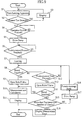
- FIG. 13 is a flowchart illustrating operation control by the controller.
- FIG. 14 is a sectional view illustrating the state in which the skin is bulged.
- FIG. 15 is a sectional view illustrating the state in which the skin is lanced.
- FIG. 16 is a sectional view illustrating the state after the skin is lanced.
- FIG. 17 illustrates positional relationship between skin and the analysis sensor.
- FIG. 18 illustrates positional relationship between skin and the analysis sensor.
- FIG. 19 is a sectional view illustrating a principal portion of another lancing apparatus according to the present invention.
- FIG. 20 is a sectional view illustrating a principal portion of another lancing apparatus according to the present invention.
- FIG. 21 is a sectional view illustrating a principal portion of another lancing apparatus according to the present invention.
- FIG. 22 is a sectional view illustrating a principal portion of another lancing apparatus according to the present invention.
- FIGS. 1 through 7 illustrate an embodiment of the present invention.
- the lancing apparatus A in this embodiment includes a housing 2 , a case 39 partially covering the housing 2 , a display 21 for displaying an image, and operation switches 22 and 23 .
- the display 21 may comprise a liquid crystal display or an LED display, for example.
- the case 39 incorporates a controller 9 , which will be described later.
- the housing 2 has a lower front end formed with a cylindrical member 20 .
- a cylindrical member 8 formed separately from the housing 2 .
- the front end 8 a of the cylindrical member 8 is pressed against the skin to be lanced.
- the cylindrical member 8 is supported by a flange 24 formed on an inner wall of the housing 2 via a spring 83 and is axially slidable relative to the cylindrical member 20 by expanding and contracting the spring 83 .
- the flange 24 is provided with a pressure sensor 25 for measuring the magnitude of the resilient force of the spring 83 , and the measurement data is inputted into the controller 9 .
- the lancing apparatus A further includes a lancet 3 , an analysis sensor 4 as an analysis component, a holder 7 for holding the analysis sensor 4 , a pump 26 and a relief valve 28 .
- the lancet 3 and the analysis sensor 4 when used are mounted at predetermined positions in the lancing apparatus A and detached after use for replacement with new ones.
- such replacement parts are also components of the lancing apparatus.
- the lancet 3 includes a main body 3 b formed of synthetic resin, and a needle 3 a formed of metal and projecting from the lower surface of the main body.
- the lancet 3 is detachably mounted to a lancet holder 31 provided in the housing 2 .
- the lancet holder 31 is reciprocally movable axially of the cylindrical member 8 (in the vertical direction in FIG. 2 ) by the driving of a lancet driving mechanism 93 , which will be described later.
- the lancet holder can move downward to advance from a deeper portion (upper portion in FIG. 2 ) in the housing 2 toward the front end opening of the cylindrical member 8 and can retreat for restoration to the deeper portion.
- the cylindrical member 8 has an upper portion formed with an opening 80 for allowing the lancet 3 to pass therethrough.
- the pump 26 which is an electrically driven pump, is connected to the housing 2 via a connection pipe 29 .
- the pump 26 can evacuate air from the inside of the housing 2 to the outside to generate negative pressure in the cylindrical member 20 of the housing 2 and in the cylindrical member 8 .
- the pump 26 is controlled by the controller 9 , as will be described later.
- the pump 26 may be attached to the outer portion of the housing 2 or may be arranged in the case 39 .
- the connection pipe 29 incorporates a pressure sensor 27 , and the pressure data measured by the pressure sensor 27 is inputted into the controller 9 .
- the relief valve 28 which may be a solenoid valve for example, may be opened for providing communication between the inside and the outside of the housing 2 and closed for interrupting the communication.
- the relief valve When the relief valve is opened with negative pressure generated in the housing 2 , the interior of the housing 2 is returned to the atmospheric pressure.
- the analysis sensor 4 which is in the form of a generally semicircular chip, comprises a substrate 40 , a pair of spacers 41 , a cover plate 42 and an adhesive sheet, which are laminated.
- the paired spacers 41 and the cover plate 42 define a capillary 46 which serves as a passage of blood on the substrate 40 .
- the spacers 41 are aligned on the substrate 40 while defining a space therebetween, and a cover plate 42 is placed thereon to cover the space from above, whereby the capillary 46 is defined.
- Each of the substrate 40 , the adhesive sheet 43 and the paired spacers 41 is partially cut away to define a sample introducing portion 47 as a recess.
- the blood travels through the capillary 46 by capillary action to be guided to the portion of the reagent 44 sandwiched between the paired electrodes 45 .
- a lower surface portion of the cover plate 42 defining the sample introducing portion 47 is hydrophilically treated by applying or attaching a hygroscopic material 49 .
- the hygroscopic material 49 use may be made of Vinylon. The hydrophilic treatment is advantageous for smoothly guiding the blood adhered to the sample introducing portion 47 to the capillary.
- the hygroscopic material 49 may be applied to portions other than the above-described portion.
- the spacers 41 are respectively formed with holes 41 a , whereas the cover plate 42 is formed with a pair of holes 42 a communicating with the holes 41 a .
- the holes 41 a and 42 a are used for passing a pair of measurement probes 75 for coming into contact with the paired electrodes 45 .
- the reagent 44 contacts blood, e.g. glucose in the blood is oxidized by oxidation reaction, whereas electron carriers in the reagent 44 are reduced by electrons from the reaction.
- the proportion of the electron carriers reduced corresponds to the proportion of glucose contained in blood, namely the glucose concentration, and the glucose concentration corresponds to the value of current flowing between the paired electrodes 45 . Therefore, the glucose concentration in blood can be figured out based on the value of the current.
- the adhesive sheet 43 is bonded to a reverse (lower) surface of the substrate 40 .
- the adhesive sheet 43 may comprise a gel sheet containing water gel and acrylic resin, or preferably a silicone gel sheet, thereby providing adhesion.
- the lower surface 43 a of the adhesive sheet 43 is a surface for contact with the skin.
- a double-sided adhesive tape for providing adhesion may be bonded to the analysis sensor 4 .
- the sensor holder 7 has a mount surface 73 to which the analysis sensor 4 is mounted by bonding, for example.
- the mount surface 73 is inclined downwardly.
- the sensor holder 7 is suspended from the cylindrical member 8 via a spring 74 . Therefore, the sensor holder 7 is reciprocally movable axially of the cylindrical member 8 by expanding and contracting the spring 74 .
- the analysis sensor 4 is also inclined. Accordingly, the surface 43 a of the analysis sensor 4 for contact with the skin is inclined to be progressively closer to the central axis of the cylindrical member 8 as it extends deeper (upward in FIG. 2 ) into the cylindrical member 8 .
- the analysis sensor 4 is mounted to the sensor holder 7 with the sample introducing portion 47 located close to the central axis of the cylindrical member 8 .
- the sensor holder 7 is formed with a hole 70 for allowing the downwardly advancing lancet 3 to pass through.
- the hole 70 does not allow the lancet 3 to pass through entirely, and the periphery of the hole 70 partially serves as a stopper 76 which engages the lower end of the main body 3 b of the lancet 3 for preventing the lancet 3 from further advancing.
- the paired measurement probes 75 are attached to the sensor holder 7 .
- the measurement probes 75 are so mounted that the tip ends thereof contact the paired electrodes 45 of the analysis sensor 4 .
- the tip end of each probe 75 is extendable and retractable and is biased downward by the resilient force of a spring for press contact with the electrode 45 under an appropriate pressing force.
- the controller 9 is connected to a current measurer 91 , the pump 26 , the relief valve 28 , the lancet driving mechanism 93 , a memory 92 , the display 21 , the pressure sensors 25 and 27 , and the operation switch 22 .
- the current measurer 91 applies a voltage across the paired electrodes 45 of the analysis sensor 4 by utilizing the measurement probes 75 and measures the current flowing between the electrodes 45 .
- the controller 9 calculates the glucose concentration based on the current measured by the current measurer 91 .
- the controller 9 which may comprise a CPU for example, performs various kinds of control based on a control program stored in the memory 92 and on electric signals from the operation switch 22 and the pressure sensors 25 , 27 , as will be described later.
- the controller 9 also has a function as a determiner for determining whether or not blood is properly supplied to the reagent 44 in the analysis sensor 4 , as will also be described later.
- the memory 92 which may comprise a ROM or a RAM, stores data necessary for the control by the controller 9 .
- Step S 1 the front end 8 a of the cylindrical member 8 of the lancing apparatus A is pressed against the skin S of a human body as a target of lancing.
- the controller 9 checks whether the front end 8 a is pressed against the skin S too strongly or not (Step 2 ). Specifically, when the front end 8 a is pressed against the skin S, the pressure sensor 25 measures the pressing force. When the measurement value exceeds a predetermined value, the controller 9 determines that the user is pressing the front end 8 a too strongly against the skin S (Step S 2 : YES), and causes the display 21 to display a notice to that effect (Step S 3 ).
- the user can make adjustments to press the front end 8 a against the skin S with a proper pressing force. In this way, it is possible to prevent excessive tension of the skin S which may cause insufficient bulging when the pressure in the cylindrical member 8 is reduced for bulging the skin S, as will be described later.
- Step S 4 when the user presses the operation switch 22 of the case 2 (Step S 4 : YES), the controller 9 drives the pump 26 (Step S 5 ).
- the controller 9 drives the pump 26 (Step S 5 ).
- negative pressure is generated in the cylindrical member 8 .
- the skin S bulges as shown in FIG. 14 to come into contact with the skin contact surface 43 a of the analysis sensor 4 .
- the surface 43 a is inclined, it closely fits to an inclined surface of the bulged portion of the skin S.
- the surface 43 a is provided by the adhesive surface of the adhesive sheet 43 , the adhesion of the analysis sensor to the skin S is further enhanced. Since the analysis sensor 4 closely fits to the skin S to avoid formation of a large gap between the analysis sensor 4 and the skin S, the blood is prevented from unduly flowing into such a gap.
- the controller 9 monitors pressure measurements by the pressure sensor 27 and determines whether or not the measured pressure has reached a predetermined value (Step S 6 ). If the controller 9 determines that the measured pressure has not reached the predetermined value (Step S 6 : NO), the controller continues the driving of the pump 26 to further lower the pressure in the cylindrical member 8 . Thus, the skin S further bulges to push the analysis sensor 4 upward. As a result, the analysis sensor 4 moves upward while contracting the spring 74 . The analysis sensor 4 stops at the position where the bulging force of the skin S and the resisting force of the spring 74 are in equilibrium.
- the analysis sensor 4 since the analysis sensor 4 is lifted following the bulging of the skin S, the analysis sensor 4 does not unduly inhibit the bulging of the skin S. Further, the positional relationship between the top of the bulging portion of the skin S and the sample introducing portion 47 is kept generally constant regardless of how much the skin S bulges. This is preferable for properly guiding the blood to the sample introducing portion 47 of the analysis sensor 4 , as will be described later.
- Step S 6 If the controller 9 determines that the pressure measured by the pressure sensor 27 has reached the predetermined value (Step S 6 : YES), the controller 9 drives the lancet driving mechanism 93 . As a result, the lancet holder 31 and the lancet 3 advance into the cylindrical member 8 and then retreat to their original position. As shown in FIG. 15 , when the lancet 3 advances, the needle 3 a sticks into the skin S (Step S 7 ). During this advancing movement of the lancet 3 , the main body 3 b engages the stopper 76 , so that the lancet 3 is prevented from advancing more than a predetermined distance. Thus, the needle 3 a is prevented from sticking into the skin S more than a predetermined amount, thereby avoiding great damage to the skin S.
- the advancing/retreating movement of the lancet 3 may be performed by the user's manipulation of the operation switch 23 without relying on the controller 9 .
- the controller 9 instructs the display 21 to indicate that the driving of the lancet 3 is allowable.
- the user presses the operation switch 23 to move the lancet 3 .
- the above lancing causes bleeding from the skin S.
- the negative pressure generated in the cylindrical member 8 promotes the bleeding from the skin S.
- the blood b from the skin S tends to flow along the surface of the bulged skin S.
- the analysis sensor 4 since the analysis sensor 4 is in close contact with the skin S as previously noted, the blood b cannot flow between the sensor and the skin. Therefore, the blood b is properly guided to the sample introducing portion 47 .
- the analysis sensor 4 moves upward following the bulging of the skin S, so that the positional relationship between the top of the bulging portion of the skin S and the sample introducing portion 47 is kept generally constant. Therefore, the sample introducing portion 47 can be kept close to the bleeding portion regardless of the degree of bulging of the skin S.
- the sample introducing portion 47 opens widely as compared with the capillary 46 , which is also advantageous for reliable guiding of the blood b to the sample introducing portion 47 .
- the blood guided to the sample introducing portion 47 travels through the capillary 46 by capillary action. Since the hygroscopic material 49 provided at the sample introducing portion 47 is highly hydrophilic, the blood b is unlikely to stagnate between the sample introducing portion 47 and the skin S, whereby the travelling of the blood b to the capillary 46 is promoted. The blood b travelling in this way is readily supplied to the reagent 44 .
- the controller 9 determines whether or not a sufficient amount of blood needed for concentration measurement is supplied to the reagent 44 (Step S 8 ). Specifically, upon supply of an amount of blood b to the reagent 44 , the above-described redox reaction occurs, which causes current to flow between the paired electrodes 45 . When the current exceeds a predetermined threshold value, the controller 9 determines that the amount of the blood supplied to the reagent 44 is sufficient (Step S 8 : YES). When the controller 9 determines that the amount of blood b supplied is not sufficient (Step S 8 : NO), the controller continues to monitor whether or not the blood b is sufficiently supplied until a predetermined time elapses (Step S 12 ).
- Step S 8 determines that the blood b is properly supplied to the reagent 44 (Step S 8 : YES)
- the controller stops the driving of the pump 26 while opening the relief valve 28 (Step S 9 ).
- the interior of the cylindrical member 8 returns to the atmospheric pressure, which makes it easy to remove the cylindrical member 8 from the skin S.
- the controller 9 calculates the glucose concentration in the blood b based on the value of the current measured by the current measurer 91 (Step S 10 ) and instructs the display 21 to show the resulting value (Step S 11 ).
- the analysis sensor 4 follows the bulging of the skin S. Therefore, the blood b can be reliably guided to the sample introducing portion 47 of the analysis sensor 4 .
- the degree of bulging of the skin S varies largely depending on e.g. the softness and thickness of the skin S. Therefore, even with an equal level of negative pressure, the degree of bulging of the skin S may sometimes be extremely large or extremely small. In such a case, the blood b may not be properly guided to the sample introducing portion 47 . In that case, the lancing apparatus A in this embodiment performs secondary control to readily guide the blood b to the sample introducing portion 47 .
- Step S 12 YES
- the controller 9 stops the driving of the pump 26 while opening the relief valve 28 , as shown in FIG. 16 (Step S 13 ). As a result, the negative pressure in the cylindrical member 8 is relieved.
- the internal pressure of the cylindrical member 8 may be gradually returned to the atmospheric pressure by adjusting the opening degree of the relief valve 28 and the driving of the pump 26 under control of the controller 9 .
- the skin S may bulge largely as shown in FIG. 17 if the skin S is considerably soft.
- the top of the bulging portion is locally swelled.
- part of the sensor holder 7 may block the path from the bleeding portion to the sample introducing portion 47 . In such a case, proper guiding of the blood b to the sample introducing portion 47 is difficult.
- the pressure in the cylindrical member 8 is gradually returned to the atmospheric pressure as noted above, the local swelling at the top of the skin S shrinks with the analysis sensor 4 closely contacting the skin S for a while. Therefore, the bleeding portion comes closer to the sample introducing portion 47 , and part of the sensor holder 7 does not block the path from the bleeding portion to the sample introducing portion 47 . Therefore, the blood b can be reliably guided to the sample introducing portion 47 . It is preferable that the increasing of pressure in the cylindrical member 8 is performed as slowly as possible so that the bulged portion of the skin S shrinks slowly. By this, the bleeding portion and the sample introducing portion 47 can be located close to each other for a relatively long time, which contributes to reliable guiding of the blood b to the sample introducing portion 47 .
- Step S 14 determines again whether or not the blood b is properly supplied to the reagent 44 (Step S 14 ). This process step is performed similarly to Step S 8 . If it is determined that the blood b is properly supplied to the reagent 44 (Step S 14 : YES), the process proceeds to Step S 10 and the following step similarly to the above.
- Step S 14 determines whether or not the controller has checked the proper guiding of the blood b to the sample introducing portion 47 more than a predetermined number of times (Step S 15 ). If the number of checks exceeds the predetermined value (Step S 15 : YES), the controller 9 determines that the measurement of glucose concentration is impossible and instructs the display 21 to show a notice to that effect (Step S 16 ).
- Step S 15 if the number of checks does not exceed the predetermined value (Step S 15 : NO), the controller 9 drives the pump 26 (Step S 17 ). As a result, the interior of the cylindrical member 8 undergoes a pressure drop again, whereby the skin S is bulged.
- the following control mode by the controller 9 is a pseudo-massage mode, which provides advantages similar to those provided by massaging the surface of the skin S with fingers (Step S 18 ).
- Step S 21 the pump 26 is stopped while the relief valve 28 is opened (Step S 21 ), as shown in FIG. 10 .
- Step S 22 the relief valve 28 is closed and the pump 26 is driven (Step 23 ), thereby increasing negative pressure.
- Step S 24 The above series of operations are repeated a predetermined number of times (Step S 24 ).
- the pressure variation caused in this way provides the skin S with effects like those provided by massaging the skin. Therefore, the blood circulation is promoted, which promotes bleeding from the skin S.
- the blood circulation promoting effect does not necessarily increase in proportion to the number of repetitions of pressure variation.
- Step S 25 a predetermined negative level after the pressure variation is repeated a predetermined number of times (Step S 25 : YES)
- the process by the controller 9 returns to Step S 8 in FIG. 9 . In this way, even when the measurement of glucose concentration in blood b seems to be impossible due to insufficient bleeding from the skin S, proper measurement of the blood glucose concentration becomes possible by performing the pseudo-massage mode.
- FIGS. 11 through 13 are flowcharts illustrating other examples of operation control of the lancing apparatus A.
- Step S 7 ′ the pseudo-massage mode shown in FIG. 10 is performed as Step S 7 ′, which is performed directly after the skin S is lanced by the lancet 3 in Step S 7 . Thereafter, determination is made as to whether or not the blood b is properly supplied to the reagent 44 (Step S 8 ).
- Step S 17 is performed in which the pump 26 is driven to generate a negative pressure in the cylinder body 8 again.
- the lancing of the skin S in Step S 7 is performed again after the negative pressure is generated again.
- the blood b can be properly supplied to the reagent 44 of the analysis sensor 4 by performing the second lancing at the proper position.
- the relief valve 28 is opened to relieve the negative pressure in the cylindrical member 8 (Step S 13 ) after it is determined that blood b is not supplied to the analysis sensor 4 (Step S 8 : NO).
- the pseudo-massage mode shown in FIG. 10 may be performed.
- the lancing of the skin S may be performed again.
- FIG. 13 shows a flowchart of operation control which may replace the process steps of the foregoing operation control subsequent to Step S 4 for making determination as to the pressing of the operation switch 22 and prior to Step S 8 for making determination as to whether or not blood b is properly supplied to the reagent 44 .
- Step S 31 the controller 9 drives the pump 26 (Step S 31 ) to depressurize the cylindrical member 8 and then determines whether or not the pressure measured by the pressure sensor 27 has reached a predetermined first value (Step S 32 ).
- the first pressure is lower than the atmospheric pressure and higher than a second pressure to be described later.
- Step S 33 the controller 9 temporarily stops the driving of the pump 26 (Step S 33 ).
- the interior of the cylindrical member 8 is kept at a pressure slightly lower than the atmospheric pressure, thereby causing the skin S to bulge.
- the degree of bulging in this stage is such a level that brings the skin into contact with the surface 43 a but does not cause the analysis sensor 4 to be raised by the skin.
- the controller 9 causes the lancing operation (Step S 34 ) and then drives the pump 26 again (Step S 35 ).
- Step S 36 determines whether or not the pressure measured by the pressure sensor 27 has reached the second value (Step S 36 ).
- Step S 36 the driving of the pump 26 is stopped (Step S 37 ).
- the skin S further bulges toward a deeper portion in the cylindrical member 8 , and the bulging amount is large.
- bleeding from the skin S is promoted due to the growth of the cut formed at the skin S by lancing as well as due to the additional suction under the negative pressure. Therefore, in this control again, it is possible to supply a sufficient amount of blood b to the reagent 44 of the analysis sensor 4 .
- FIGS. 19 through 22 illustrate other structural examples of lancing apparatus according to the present invention.
- the elements which are identical or similar to those of the above-described embodiment are designated by the same reference signs as those used for the foregoing embodiment.
- the lancing apparatus shown in FIGS. 19 and 20 differs from that of the foregoing embodiment in that the analysis sensor 4 held by the sensor holder 7 B can vary its inclination angle ⁇ .
- the sensor holder 7 B includes a pivot member 79 which is pivotable about a support shaft 78 axially of the cylindrical member 8 .
- the analysis sensor 4 is attached to the pivot member 79 so that the inclination angle ⁇ of the analysis sensor 4 varies in accordance with the pivotal movement of the pivot member 79 .
- Adjacent to the pivot member 79 of the sensor holder 7 B is provided a stopper 77 a . When the inclination angle ⁇ reaches a predetermined angle, the stopper engages the pivot member 79 to restrain the rotation of the pivot member 79 so that the inclination angle ⁇ does not exceed the predetermined angle.
- the blood b can be properly guided to the sample introducing portion 47 of the analysis sensor 4 . Since the inclination angle ⁇ is prevented from exceeding a predetermined value, the analysis sensor 4 does not rotate excessively to be spaced from the skin S even when the amount of bulging of the skin S is large.
- the analysis sensor 4 and the pivot member 79 pivot downward by their own weight, following the shrinkage of the bulge of the skin S.
- the analysis sensor 4 is not inclined.
- the sample introducing portion 47 is closer to the bleeding portion than when the analysis sensor 4 is inclined due to the bulging of the skin S. Therefore, this condition is further suitable for guiding much blood to the sample introducing portion 47 .
- the pivotal movement of the pivot member 79 in the direction to reduce the inclination angle ⁇ may be produced by utilizing e.g. the resilient force of a spring, not by utilizing its own weight. In such a case, the analysis sensor 4 can follow the shrinkage of the bulge of the skin S even when the lancing apparatus is used in a horizontal posture or an inclined posture.
- FIG. 21 does not include a member corresponding to the cylindrical member 8 of the foregoing embodiments.
- a sensor holder 7 holding an analysis sensor 4 is disposed in a cylindrical member 20 formed integrally on a housing 2 to be movable upward and downward via a spring 74 .
- the front end of the cylindrical member 20 is pressed against the skin S.
- the analysis sensor 4 and the sensor holder 7 are lifted against the resilient force of the spring 74 .
- the sensor holder 7 ′ is fixedly mounted to the cylindrical member 8 .
- the cylindrical member 8 is slidably fitted in the cylindrical member 20 of the housing 2 so as not to project downward from the cylindrical member 20 and is biased downward by a spring 74 ′.
- the sensor holder 7 ′ can move upward and downward in accordance with the up and down movement of the cylindrical member 8 . Therefore, it is possible to make the sensor holder 7 ′ move upward and downward following the bulging of the skin S.
- the present invention is not limited to the above-described embodiments.
- the specific structure of each part of the lancing apparatus according to the present invention may be varied in various ways.
- the usage of the lancing apparatus according to the present invention is not limited to measurement of glucose concentration in blood.
- the apparatus of the present invention can be used for various kinds of measurement or analysis other than that described above.
- the analysis component of the present invention need not necessarily include a reagent, but may only have the function for sampling blood.
- the lancing apparatus according to the present invention includes an analyer for analyzing a sample, the present invention is not limited thereto, and the lancing apparatus may not have the function for analyzing the sample extracted to the analysis component.
- the negative pressure generator comprise an electrically driven pump.
- the negative pressure generator use may be alternatively made of a manual pump or a pump mechanism which generates negative pressure in the cylindrical member utilizing the advancing movement of the lancet.
- the resilient force of a resilient member may be utilized for the advancing movement, whereas the retreating movement may be performed manually.
- both of the advancing movement and the retreating movement may be performed utilizing the resilient force of a resilient member such as a spring.
Abstract
Description
Claims (21)
Applications Claiming Priority (5)
| Application Number | Priority Date | Filing Date | Title |
|---|---|---|---|
| JP2001220259 | 2001-07-19 | ||
| JP2001-220259 | 2001-07-19 | ||
| JP2001-236976 | 2001-08-03 | ||
| JP2001236976 | 2001-08-03 | ||
| PCT/JP2002/007333 WO2003007819A1 (en) | 2001-07-19 | 2002-07-18 | Piercing device |
Publications (2)
| Publication Number | Publication Date |
|---|---|
| US20040215224A1 US20040215224A1 (en) | 2004-10-28 |
| US8016773B2 true US8016773B2 (en) | 2011-09-13 |
Family
ID=26619044
Family Applications (1)
| Application Number | Title | Priority Date | Filing Date |
|---|---|---|---|
| US10/483,909 Expired - Fee Related US8016773B2 (en) | 2001-07-19 | 2002-07-18 | Lancing apparatus |
Country Status (5)
| Country | Link |
|---|---|
| US (1) | US8016773B2 (en) |
| EP (1) | EP1407712B1 (en) |
| JP (2) | JP4250698B2 (en) |
| CN (1) | CN1310618C (en) |
| WO (1) | WO2003007819A1 (en) |
Cited By (3)
| Publication number | Priority date | Publication date | Assignee | Title |
|---|---|---|---|---|
| US20090318834A1 (en) * | 2006-03-22 | 2009-12-24 | Matsushita Electric Industrial Co., Ltd. | Blood test device |
| KR101329563B1 (en) | 2011-12-13 | 2013-11-15 | 연세대학교 산학협력단 | Devices for Extracting Body Fluid |
| US20150351676A1 (en) * | 2014-06-10 | 2015-12-10 | Labatm, Inc. | Automatic Blood Collection |
Families Citing this family (98)
| Publication number | Priority date | Publication date | Assignee | Title |
|---|---|---|---|---|
| US6036924A (en) | 1997-12-04 | 2000-03-14 | Hewlett-Packard Company | Cassette of lancet cartridges for sampling blood |
| US6391005B1 (en) | 1998-03-30 | 2002-05-21 | Agilent Technologies, Inc. | Apparatus and method for penetration with shaft having a sensor for sensing penetration depth |
| US7767781B2 (en) | 2000-09-01 | 2010-08-03 | Cyclics Corporation | Preparation of low-acid polyalkylene terephthalate and preparation of macrocyclic polyester oligomer therefrom |
| US8641644B2 (en) | 2000-11-21 | 2014-02-04 | Sanofi-Aventis Deutschland Gmbh | Blood testing apparatus having a rotatable cartridge with multiple lancing elements and testing means |
| US7025774B2 (en) | 2001-06-12 | 2006-04-11 | Pelikan Technologies, Inc. | Tissue penetration device |
| CA2448902C (en) | 2001-06-12 | 2010-09-07 | Pelikan Technologies, Inc. | Self optimizing lancing device with adaptation means to temporal variations in cutaneous properties |
| AU2002344825A1 (en) | 2001-06-12 | 2002-12-23 | Pelikan Technologies, Inc. | Method and apparatus for improving success rate of blood yield from a fingerstick |
| US8337419B2 (en) | 2002-04-19 | 2012-12-25 | Sanofi-Aventis Deutschland Gmbh | Tissue penetration device |
| CA2448905C (en) | 2001-06-12 | 2010-09-07 | Pelikan Technologies, Inc. | Blood sampling apparatus and method |
| WO2002100254A2 (en) | 2001-06-12 | 2002-12-19 | Pelikan Technologies, Inc. | Method and apparatus for lancet launching device integrated onto a blood-sampling cartridge |
| US9427532B2 (en) | 2001-06-12 | 2016-08-30 | Sanofi-Aventis Deutschland Gmbh | Tissue penetration device |
| US7981056B2 (en) | 2002-04-19 | 2011-07-19 | Pelikan Technologies, Inc. | Methods and apparatus for lancet actuation |
| US9226699B2 (en) | 2002-04-19 | 2016-01-05 | Sanofi-Aventis Deutschland Gmbh | Body fluid sampling module with a continuous compression tissue interface surface |
| ES2352998T3 (en) | 2001-06-12 | 2011-02-24 | Pelikan Technologies Inc. | LANCETA ELECTRIC ACTUATOR. |
| US9795747B2 (en) | 2010-06-02 | 2017-10-24 | Sanofi-Aventis Deutschland Gmbh | Methods and apparatus for lancet actuation |
| US8116845B2 (en) | 2005-08-04 | 2012-02-14 | Dune Medical Devices Ltd. | Tissue-characterization probe with effective sensor-to-tissue contact |
| US7674232B2 (en) | 2002-04-19 | 2010-03-09 | Pelikan Technologies, Inc. | Method and apparatus for penetrating tissue |
| US7491178B2 (en) | 2002-04-19 | 2009-02-17 | Pelikan Technologies, Inc. | Method and apparatus for penetrating tissue |
| US8360992B2 (en) | 2002-04-19 | 2013-01-29 | Sanofi-Aventis Deutschland Gmbh | Method and apparatus for penetrating tissue |
| US9248267B2 (en) | 2002-04-19 | 2016-02-02 | Sanofi-Aventis Deustchland Gmbh | Tissue penetration device |
| US7648468B2 (en) | 2002-04-19 | 2010-01-19 | Pelikon Technologies, Inc. | Method and apparatus for penetrating tissue |
| US8372016B2 (en) | 2002-04-19 | 2013-02-12 | Sanofi-Aventis Deutschland Gmbh | Method and apparatus for body fluid sampling and analyte sensing |
| US8579831B2 (en) | 2002-04-19 | 2013-11-12 | Sanofi-Aventis Deutschland Gmbh | Method and apparatus for penetrating tissue |
| US7901362B2 (en) | 2002-04-19 | 2011-03-08 | Pelikan Technologies, Inc. | Method and apparatus for penetrating tissue |
| US7297122B2 (en) | 2002-04-19 | 2007-11-20 | Pelikan Technologies, Inc. | Method and apparatus for penetrating tissue |
| US7229458B2 (en) | 2002-04-19 | 2007-06-12 | Pelikan Technologies, Inc. | Method and apparatus for penetrating tissue |
| US8784335B2 (en) | 2002-04-19 | 2014-07-22 | Sanofi-Aventis Deutschland Gmbh | Body fluid sampling device with a capacitive sensor |
| US8267870B2 (en) | 2002-04-19 | 2012-09-18 | Sanofi-Aventis Deutschland Gmbh | Method and apparatus for body fluid sampling with hybrid actuation |
| US7717863B2 (en) | 2002-04-19 | 2010-05-18 | Pelikan Technologies, Inc. | Method and apparatus for penetrating tissue |
| US9314194B2 (en) | 2002-04-19 | 2016-04-19 | Sanofi-Aventis Deutschland Gmbh | Tissue penetration device |
| US7547287B2 (en) | 2002-04-19 | 2009-06-16 | Pelikan Technologies, Inc. | Method and apparatus for penetrating tissue |
| US7232451B2 (en) | 2002-04-19 | 2007-06-19 | Pelikan Technologies, Inc. | Method and apparatus for penetrating tissue |
| US7371247B2 (en) | 2002-04-19 | 2008-05-13 | Pelikan Technologies, Inc | Method and apparatus for penetrating tissue |
| US7331931B2 (en) | 2002-04-19 | 2008-02-19 | Pelikan Technologies, Inc. | Method and apparatus for penetrating tissue |
| US7175642B2 (en) | 2002-04-19 | 2007-02-13 | Pelikan Technologies, Inc. | Methods and apparatus for lancet actuation |
| US7909778B2 (en) | 2002-04-19 | 2011-03-22 | Pelikan Technologies, Inc. | Method and apparatus for penetrating tissue |
| US7713214B2 (en) | 2002-04-19 | 2010-05-11 | Pelikan Technologies, Inc. | Method and apparatus for a multi-use body fluid sampling device with optical analyte sensing |
| US7291117B2 (en) | 2002-04-19 | 2007-11-06 | Pelikan Technologies, Inc. | Method and apparatus for penetrating tissue |
| US7892183B2 (en) | 2002-04-19 | 2011-02-22 | Pelikan Technologies, Inc. | Method and apparatus for body fluid sampling and analyte sensing |
| US7976476B2 (en) | 2002-04-19 | 2011-07-12 | Pelikan Technologies, Inc. | Device and method for variable speed lancet |
| US8221334B2 (en) | 2002-04-19 | 2012-07-17 | Sanofi-Aventis Deutschland Gmbh | Method and apparatus for penetrating tissue |
| US8702624B2 (en) | 2006-09-29 | 2014-04-22 | Sanofi-Aventis Deutschland Gmbh | Analyte measurement device with a single shot actuator |
| US9795334B2 (en) | 2002-04-19 | 2017-10-24 | Sanofi-Aventis Deutschland Gmbh | Method and apparatus for penetrating tissue |
| EP1581114B1 (en) * | 2002-12-30 | 2014-04-30 | Roche Diagnostics GmbH | Flexible test strip lancet device |
| US7214200B2 (en) * | 2002-12-30 | 2007-05-08 | Roche Diagnostics Operations, Inc. | Integrated analytical test element |
| US8574895B2 (en) | 2002-12-30 | 2013-11-05 | Sanofi-Aventis Deutschland Gmbh | Method and apparatus using optical techniques to measure analyte levels |
| EP2238892A3 (en) | 2003-05-30 | 2011-02-09 | Pelikan Technologies Inc. | Apparatus for body fluid sampling |
| US7850621B2 (en) | 2003-06-06 | 2010-12-14 | Pelikan Technologies, Inc. | Method and apparatus for body fluid sampling and analyte sensing |
| WO2006001797A1 (en) | 2004-06-14 | 2006-01-05 | Pelikan Technologies, Inc. | Low pain penetrating |
| WO2005033659A2 (en) | 2003-09-29 | 2005-04-14 | Pelikan Technologies, Inc. | Method and apparatus for an improved sample capture device |
| WO2005037095A1 (en) | 2003-10-14 | 2005-04-28 | Pelikan Technologies, Inc. | Method and apparatus for a variable user interface |
| US7481818B2 (en) * | 2003-10-20 | 2009-01-27 | Lifescan | Lancing device with a floating probe for control of penetration depth |
| US20050096686A1 (en) | 2003-10-31 | 2005-05-05 | Allen John J. | Lancing device with trigger mechanism for penetration depth control |
| US8668656B2 (en) | 2003-12-31 | 2014-03-11 | Sanofi-Aventis Deutschland Gmbh | Method and apparatus for improving fluidic flow and sample capture |
| US7822454B1 (en) | 2005-01-03 | 2010-10-26 | Pelikan Technologies, Inc. | Fluid sampling device with improved analyte detecting member configuration |
| DE102004002874A1 (en) * | 2004-01-20 | 2005-08-11 | Roche Diagnostics Gmbh | Analyzer for analysis of blood samples |
| CN1942139A (en) * | 2004-04-10 | 2007-04-04 | 霍夫曼-拉罗奇有限公司 | Method and system for taking body fluid |
| EP1751546A2 (en) | 2004-05-20 | 2007-02-14 | Albatros Technologies GmbH & Co. KG | Printable hydrogel for biosensors |
| WO2005120365A1 (en) | 2004-06-03 | 2005-12-22 | Pelikan Technologies, Inc. | Method and apparatus for a fluid sampling device |
| US9775553B2 (en) * | 2004-06-03 | 2017-10-03 | Sanofi-Aventis Deutschland Gmbh | Method and apparatus for a fluid sampling device |
| US7766845B2 (en) * | 2004-06-21 | 2010-08-03 | Roche Diagnostics Operations, Inc. | Disposable lancet and lancing cap combination for increased hygiene |
| DE102004059491B4 (en) * | 2004-12-10 | 2008-11-06 | Roche Diagnostics Gmbh | Lancet device for creating a puncture wound and lancet drive assembly |
| GB0427891D0 (en) * | 2004-12-21 | 2005-01-19 | Owen Mumford Ltd | Skin pricking apparatus |
| US8652831B2 (en) | 2004-12-30 | 2014-02-18 | Sanofi-Aventis Deutschland Gmbh | Method and apparatus for analyte measurement test time |
| DE102005005017A1 (en) * | 2005-02-03 | 2006-08-17 | Roche Diagnostics Gmbh | Electromechanical lancing device for obtaining liquid samples |
| US7695442B2 (en) * | 2005-04-12 | 2010-04-13 | Roche Diagnostics Operations, Inc. | Integrated lancing test strip with retractable lancet |
| WO2006109452A1 (en) * | 2005-03-31 | 2006-10-19 | Terumo Kabushiki Kaisha | Centesis instrument |
| ATE472972T1 (en) * | 2005-04-04 | 2010-07-15 | Facet Technologies Llc | NARROW PROFILE LANCET DEVICE |
| WO2006123665A1 (en) * | 2005-05-16 | 2006-11-23 | Terumo Kabushiki Kaisha | Blood component measurement device and chip for blood measurement |
| US20070060844A1 (en) * | 2005-08-29 | 2007-03-15 | Manuel Alvarez-Icaza | Applied pressure sensing cap for a lancing device |
| US8801631B2 (en) | 2005-09-30 | 2014-08-12 | Intuity Medical, Inc. | Devices and methods for facilitating fluid transport |
| ATE513511T1 (en) * | 2005-10-08 | 2011-07-15 | Hoffmann La Roche | STICKING SYSTEM |
| CA2640970A1 (en) | 2006-01-31 | 2007-08-09 | Matsushita Electric Industrial Co., Ltd. | Blood test method and blood test apparatus |
| CN101374458B (en) * | 2006-01-31 | 2012-04-18 | 松下电器产业株式会社 | Blood sensor and blood test apparatus having the same |
| JP4944803B2 (en) * | 2006-02-09 | 2012-06-06 | パナソニック株式会社 | Blood test equipment |
| JPWO2007108518A1 (en) * | 2006-03-22 | 2009-08-06 | パナソニック株式会社 | Blood test apparatus and control method thereof |
| EP1891898A1 (en) * | 2006-08-25 | 2008-02-27 | Roche Diagnostics GmbH | Lancing device |
| US20110092854A1 (en) * | 2009-10-20 | 2011-04-21 | Uwe Kraemer | Instruments and system for producing a sample of a body fluid and for analysis thereof |
| JPWO2009011138A1 (en) * | 2007-07-18 | 2010-09-16 | パナソニック株式会社 | Puncture device, blood test device, and puncture method |
| JP5546243B2 (en) * | 2007-07-18 | 2014-07-09 | パナソニックヘルスケア株式会社 | Blood test equipment |
| US9386944B2 (en) | 2008-04-11 | 2016-07-12 | Sanofi-Aventis Deutschland Gmbh | Method and apparatus for analyte detecting device |
| WO2009145920A1 (en) | 2008-05-30 | 2009-12-03 | Intuity Medical, Inc. | Body fluid sampling device -- sampling site interface |
| US10383556B2 (en) | 2008-06-06 | 2019-08-20 | Intuity Medical, Inc. | Medical diagnostic devices and methods |
| CA2726067C (en) | 2008-06-06 | 2020-10-20 | Intuity Medical, Inc. | Detection meter and mode of operation |
| EP2181651A1 (en) * | 2008-10-29 | 2010-05-05 | Roche Diagnostics GmbH | Instrument and system for producing a sample of a body liquid and for analysis thereof |
| US9375169B2 (en) | 2009-01-30 | 2016-06-28 | Sanofi-Aventis Deutschland Gmbh | Cam drive for managing disposable penetrating member actions with a single motor and motor and control system |
| ES2378025T3 (en) * | 2009-03-06 | 2012-04-04 | Christophe Baudouin | Device for obtaining eye samples |
| EP2506768B1 (en) | 2009-11-30 | 2016-07-06 | Intuity Medical, Inc. | Calibration material delivery devices and methods |
| US8965476B2 (en) | 2010-04-16 | 2015-02-24 | Sanofi-Aventis Deutschland Gmbh | Tissue penetration device |
| EP2584964B1 (en) | 2010-06-25 | 2021-08-04 | Intuity Medical, Inc. | Analyte monitoring devices |
| EP4339613A2 (en) | 2011-08-03 | 2024-03-20 | Intuity Medical, Inc. | Body fluid sampling arrangement |
| CN104159509B (en) * | 2012-01-10 | 2016-09-14 | 赛诺菲-安万特德国有限公司 | There is the equipment of luminous component |
| US10729386B2 (en) | 2013-06-21 | 2020-08-04 | Intuity Medical, Inc. | Analyte monitoring system with audible feedback |
| USD755372S1 (en) * | 2013-12-12 | 2016-05-03 | Daicel Corporation | Needleless syringe |
| KR102429837B1 (en) * | 2016-02-29 | 2022-08-05 | (주)아모레퍼시픽 | Evaluation device for tightening of skin and method thereof |
| CN105806536A (en) * | 2016-06-04 | 2016-07-27 | 安徽双鹤药业有限责任公司 | Device and method for detecting removal force of gasket |
| GB2592783B (en) * | 2018-09-21 | 2023-01-25 | Actuated Medical Inc | Lancing device having anesthetic feature |
| JP2019115787A (en) * | 2019-04-24 | 2019-07-18 | パイオニア株式会社 | Skin contact device |
Citations (16)
| Publication number | Priority date | Publication date | Assignee | Title |
|---|---|---|---|---|
| US5108889A (en) * | 1988-10-12 | 1992-04-28 | Thorne, Smith, Astill Technologies, Inc. | Assay for determining analyte using mercury release followed by detection via interaction with aluminum |
| JPH11347018A (en) | 1998-04-09 | 1999-12-21 | Matsushita Electric Ind Co Ltd | Humor examination device |
| JP2000000231A (en) | 1998-06-15 | 2000-01-07 | Kdk Corp | Lancet integrated type body fluid measuring instrument and attachment used by being attached to the body fluid measuring instrument |
| US6027459A (en) * | 1996-12-06 | 2000-02-22 | Abbott Laboratories | Method and apparatus for obtaining blood for diagnostic tests |
| US6048352A (en) * | 1996-05-17 | 2000-04-11 | Mercury Diagnostics, Inc. | Disposable element for use in a body fluid sampling device |
| JP2000116626A (en) | 1998-10-15 | 2000-04-25 | Kdk Corp | Humor measuring apparatus and mounting body |
| WO2000040150A1 (en) | 1999-01-04 | 2000-07-13 | Terumo Kabushiki Kaisha | Assembly having lancet and means for collecting and detecting body fluid |
| US6155992A (en) * | 1997-12-02 | 2000-12-05 | Abbott Laboratories | Method and apparatus for obtaining interstitial fluid for diagnostic tests |
| US6219574B1 (en) * | 1996-06-18 | 2001-04-17 | Alza Corporation | Device and method for enchancing transdermal sampling |
| US6332871B1 (en) * | 1996-05-17 | 2001-12-25 | Amira Medical | Blood and interstitial fluid sampling device |
| JP2002085384A (en) | 2000-09-12 | 2002-03-26 | Terumo Corp | Tip for component measuring device and component measuring device and system |
| JP2002217804A (en) | 2001-01-22 | 2002-08-02 | Nippon Soken Inc | Adaptive array antenna device |
| US6612111B1 (en) * | 2000-03-27 | 2003-09-02 | Lifescan, Inc. | Method and device for sampling and analyzing interstitial fluid and whole blood samples |
| US6706159B2 (en) * | 2000-03-02 | 2004-03-16 | Diabetes Diagnostics | Combined lancet and electrochemical analyte-testing apparatus |
| US6849052B2 (en) * | 1999-12-13 | 2005-02-01 | Arkray, Inc. | Body fluid measuring apparatus with lancet and lancet holder used for the measuring apparatus |
| US6988996B2 (en) * | 2001-06-08 | 2006-01-24 | Roche Diagnostics Operatons, Inc. | Test media cassette for bodily fluid testing device |
Family Cites Families (3)
| Publication number | Priority date | Publication date | Assignee | Title |
|---|---|---|---|---|
| DE3741726A1 (en) * | 1987-12-09 | 1989-06-22 | Ruhrchemie Ag | METHOD FOR PRODUCING TERTIAL N, N-DIMETHYLAMINES |
| US5014718A (en) * | 1988-01-22 | 1991-05-14 | Safety Diagnostics, Inc. | Blood collection and testing method |
| JP4255556B2 (en) * | 1999-01-29 | 2009-04-15 | アークレイ株式会社 | Lancet integrated measuring device |
-
2002
- 2002-07-18 CN CNB028137876A patent/CN1310618C/en not_active Expired - Lifetime
- 2002-07-18 EP EP02753195.3A patent/EP1407712B1/en not_active Expired - Lifetime
- 2002-07-18 US US10/483,909 patent/US8016773B2/en not_active Expired - Fee Related
- 2002-07-18 JP JP2003513432A patent/JP4250698B2/en not_active Expired - Lifetime
- 2002-07-18 WO PCT/JP2002/007333 patent/WO2003007819A1/en active Application Filing
-
2008
- 2008-10-06 JP JP2008259222A patent/JP4621873B2/en not_active Expired - Lifetime
Patent Citations (21)
| Publication number | Priority date | Publication date | Assignee | Title |
|---|---|---|---|---|
| US5108889A (en) * | 1988-10-12 | 1992-04-28 | Thorne, Smith, Astill Technologies, Inc. | Assay for determining analyte using mercury release followed by detection via interaction with aluminum |
| US6048352A (en) * | 1996-05-17 | 2000-04-11 | Mercury Diagnostics, Inc. | Disposable element for use in a body fluid sampling device |
| US6332871B1 (en) * | 1996-05-17 | 2001-12-25 | Amira Medical | Blood and interstitial fluid sampling device |
| US6099484A (en) | 1996-05-17 | 2000-08-08 | Amira Medical | Methods and apparatus for sampling and analyzing body fluid |
| US6219574B1 (en) * | 1996-06-18 | 2001-04-17 | Alza Corporation | Device and method for enchancing transdermal sampling |
| US6206841B1 (en) * | 1996-12-06 | 2001-03-27 | Abbott Laboratories | Method and apparatus for obtaining blood for diagnostic tests |
| US6027459A (en) * | 1996-12-06 | 2000-02-22 | Abbott Laboratories | Method and apparatus for obtaining blood for diagnostic tests |
| US6155992A (en) * | 1997-12-02 | 2000-12-05 | Abbott Laboratories | Method and apparatus for obtaining interstitial fluid for diagnostic tests |
| JPH11347018A (en) | 1998-04-09 | 1999-12-21 | Matsushita Electric Ind Co Ltd | Humor examination device |
| US6349229B1 (en) * | 1998-04-09 | 2002-02-19 | Matsushita Electric Industrial Co., Ltd. | Body fluid testing device |
| EP0988828A1 (en) | 1998-04-09 | 2000-03-29 | Matsushita Electric Industrial Co., Ltd. | Body fluid testing device |
| JP2000000231A (en) | 1998-06-15 | 2000-01-07 | Kdk Corp | Lancet integrated type body fluid measuring instrument and attachment used by being attached to the body fluid measuring instrument |
| JP2000116626A (en) | 1998-10-15 | 2000-04-25 | Kdk Corp | Humor measuring apparatus and mounting body |
| US6315738B1 (en) * | 1999-01-04 | 2001-11-13 | Terumo Kabushiki Kaisha | Assembly having lancet and means for collecting and detecting body fluid |
| WO2000040150A1 (en) | 1999-01-04 | 2000-07-13 | Terumo Kabushiki Kaisha | Assembly having lancet and means for collecting and detecting body fluid |
| US6849052B2 (en) * | 1999-12-13 | 2005-02-01 | Arkray, Inc. | Body fluid measuring apparatus with lancet and lancet holder used for the measuring apparatus |
| US6706159B2 (en) * | 2000-03-02 | 2004-03-16 | Diabetes Diagnostics | Combined lancet and electrochemical analyte-testing apparatus |
| US6612111B1 (en) * | 2000-03-27 | 2003-09-02 | Lifescan, Inc. | Method and device for sampling and analyzing interstitial fluid and whole blood samples |
| JP2002085384A (en) | 2000-09-12 | 2002-03-26 | Terumo Corp | Tip for component measuring device and component measuring device and system |
| JP2002217804A (en) | 2001-01-22 | 2002-08-02 | Nippon Soken Inc | Adaptive array antenna device |
| US6988996B2 (en) * | 2001-06-08 | 2006-01-24 | Roche Diagnostics Operatons, Inc. | Test media cassette for bodily fluid testing device |
Cited By (4)
| Publication number | Priority date | Publication date | Assignee | Title |
|---|---|---|---|---|
| US20090318834A1 (en) * | 2006-03-22 | 2009-12-24 | Matsushita Electric Industrial Co., Ltd. | Blood test device |
| US8414504B2 (en) * | 2006-03-22 | 2013-04-09 | Panasonic Corporation | Blood test device |
| KR101329563B1 (en) | 2011-12-13 | 2013-11-15 | 연세대학교 산학협력단 | Devices for Extracting Body Fluid |
| US20150351676A1 (en) * | 2014-06-10 | 2015-12-10 | Labatm, Inc. | Automatic Blood Collection |
Also Published As
| Publication number | Publication date |
|---|---|
| EP1407712B1 (en) | 2013-07-10 |
| EP1407712A1 (en) | 2004-04-14 |
| CN1529566A (en) | 2004-09-15 |
| CN1310618C (en) | 2007-04-18 |
| JP4250698B2 (en) | 2009-04-08 |
| JP2009045473A (en) | 2009-03-05 |
| JPWO2003007819A1 (en) | 2004-11-04 |
| EP1407712A4 (en) | 2009-07-08 |
| US20040215224A1 (en) | 2004-10-28 |
| WO2003007819A1 (en) | 2003-01-30 |
| JP4621873B2 (en) | 2011-01-26 |
Similar Documents
| Publication | Publication Date | Title |
|---|---|---|
| US8016773B2 (en) | Lancing apparatus | |
| JP3659919B2 (en) | Body fluid collection system | |
| US7640047B2 (en) | Test instrument, attachment, and concentration measuring apparatus | |
| US6206841B1 (en) | Method and apparatus for obtaining blood for diagnostic tests | |
| JP4272051B2 (en) | Blood sampling apparatus and method | |
| US7207952B2 (en) | Body fluid composition measuring apparatus | |
| US7824616B2 (en) | Analyzing instrument | |
| JP4944803B2 (en) | Blood test equipment | |
| KR100893275B1 (en) | Integrated sample testing meter | |
| JPH11347018A (en) | Humor examination device | |
| CN1407871A (en) | Body fluid measuring apparatus with lancet and lancet holder used for the measuring apparatus | |
| MXPA04006477A (en) | Method of lancing skin for the extraction of blood. | |
| JP2002058662A (en) | Component measuring apparatus | |
| JP2000116626A (en) | Humor measuring apparatus and mounting body | |
| JP3694563B2 (en) | Body fluid analyzer | |
| KR100975788B1 (en) | Integrated sample testing meter | |
| KR100848529B1 (en) | Body fluid sampling device |
Legal Events
| Date | Code | Title | Description |
|---|---|---|---|
| AS | Assignment |
Owner name: ARKRAY, INC., JAPAN Free format text: ASSIGNMENT OF ASSIGNORS INTEREST;ASSIGNORS:SAKATA, TETSUYA;MATSUMOTO, DAISUKE;KASAI, TOKUO;REEL/FRAME:015492/0185 Effective date: 20040105 |
|
| ZAAA | Notice of allowance and fees due |
Free format text: ORIGINAL CODE: NOA |
|
| ZAAB | Notice of allowance mailed |
Free format text: ORIGINAL CODE: MN/=. |
|
| STCF | Information on status: patent grant |
Free format text: PATENTED CASE |
|
| FEPP | Fee payment procedure |
Free format text: PAYOR NUMBER ASSIGNED (ORIGINAL EVENT CODE: ASPN); ENTITY STATUS OF PATENT OWNER: LARGE ENTITY |
|
| FPAY | Fee payment |
Year of fee payment: 4 |
|
| MAFP | Maintenance fee payment |
Free format text: PAYMENT OF MAINTENANCE FEE, 8TH YEAR, LARGE ENTITY (ORIGINAL EVENT CODE: M1552); ENTITY STATUS OF PATENT OWNER: LARGE ENTITY Year of fee payment: 8 |
|
| FEPP | Fee payment procedure |
Free format text: MAINTENANCE FEE REMINDER MAILED (ORIGINAL EVENT CODE: REM.); ENTITY STATUS OF PATENT OWNER: LARGE ENTITY |
|
| LAPS | Lapse for failure to pay maintenance fees |
Free format text: PATENT EXPIRED FOR FAILURE TO PAY MAINTENANCE FEES (ORIGINAL EVENT CODE: EXP.); ENTITY STATUS OF PATENT OWNER: LARGE ENTITY |
|
| STCH | Information on status: patent discontinuation |
Free format text: PATENT EXPIRED DUE TO NONPAYMENT OF MAINTENANCE FEES UNDER 37 CFR 1.362 |
|
| FP | Lapsed due to failure to pay maintenance fee |
Effective date: 20230913 |