US8042330B2 - Torque converter having weld free blades - Google Patents
Torque converter having weld free blades Download PDFInfo
- Publication number
- US8042330B2 US8042330B2 US12/157,690 US15769008A US8042330B2 US 8042330 B2 US8042330 B2 US 8042330B2 US 15769008 A US15769008 A US 15769008A US 8042330 B2 US8042330 B2 US 8042330B2
- Authority
- US
- United States
- Prior art keywords
- shell
- blade
- turbine
- torque converter
- pump
- Prior art date
- Legal status (The legal status is an assumption and is not a legal conclusion. Google has not performed a legal analysis and makes no representation as to the accuracy of the status listed.)
- Expired - Fee Related, expires
Links
Images


Classifications
-
- F—MECHANICAL ENGINEERING; LIGHTING; HEATING; WEAPONS; BLASTING
- F16—ENGINEERING ELEMENTS AND UNITS; GENERAL MEASURES FOR PRODUCING AND MAINTAINING EFFECTIVE FUNCTIONING OF MACHINES OR INSTALLATIONS; THERMAL INSULATION IN GENERAL
- F16H—GEARING
- F16H41/00—Rotary fluid gearing of the hydrokinetic type
- F16H41/24—Details
- F16H41/28—Details with respect to manufacture, e.g. blade attachment
Definitions
- This invention relates to a torque converter having a rotatable pump, for connection with a drive, where the pump has blades connected to a pump shell that are designed to direct fluid flow to blades on a shell of a turbine to cause the turbine to rotate.
- the turbine is designed for connection to an apparatus to be driven, usually a transmission for driving a vehicle.
- Hydraulic torque converters devices used to change the ratio of torque to speed between the input and output shafts of the converter, have revolutionized energy transfer from engines. This is especially apparent in vehicles such as automobiles, trucks, tractors, and boats where hydraulic means is provided to transfer energy from a power shaft of an engine to a drive mechanism, e.g., drive shaft or automatic transmission, while smoothing out engine power pulses.
- crankshaft a turbine, similar in structure to the impeller, however the turbine is connected to the input shaft of the transmission; and, a stator, located between the impeller and turbine, which redirects the flow of hydraulic fluid exiting from the turbine thereby providing additional rotational force to the pump.
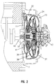
- FIG. 2 A cross sectional view of a common torque converter configuration is shown in FIG. 2 .
- the three main components of the torque converter as shown in FIG. 2 are the pump 37 , turbine 38 , and stator 39 .
- the stator is used to redirect the flow of returning fluid to increase efficiency.
- the turbine and the pump are rotatable assemblies, in large part formed in the shape of hollow shells 22 , 24 , respectively that rotate radially.
- the torque converter 10 becomes a sealed chamber when the pump 37 is welded to a cover 11 .
- the cover 11 is connected to flexplate 41 which, in turn, may be bolted to a crankshaft 42 of an engine 7 ( FIGS. 1 and 2 ).
- the cover can be connected to the flexplate using lugs or studs welded to the cover. The welded connection between the pump and cover transmits engine torque to the pump.
- the pump always rotates at engine speed.
- the function of the pump is to use this rotational motion to propel fluid radially outward and axially toward the turbine. Therefore, the pump is a centrifugal pump propelling fluid from a small radial inlet to a large radial outlet, increasing the energy in the fluid.
- a fluid circuit is created by the pump (sometimes called an impeller), the turbine, and the stator (sometimes called a reactor).
- the fluid circuit allows the engine to continue rotating when the vehicle is stopped, and to accelerate the vehicle when desired by a driver.
- the torque converter supplements engine torque through torque ratio, similar to a gear reduction.
- Turbine 38 uses the fluid energy it receives from pump 37 to propel the vehicle.
- Turbine shell 22 is connected to a turbine hub 19 .
- Turbine hub 19 usually uses a spline connection to transmit turbine torque to transmission input shaft 43 .
- the input shaft is connected to the wheels of the vehicle through gears and shafts in transmission 8 and axle differential 9 ( FIG. 1 ).
- the force of the fluid impacting the turbine blades is output from the turbine as torque.
- FIG. 2 does not clearly show means for attachment of blades to a turbine or pump. This figure may be considered non-pertinent prior art.
- Torque converters as above described are well known in the art. Traditionally, the blades have been connected to their respective pump or turbine by means of welding. It is to be understood that “welding” in this sense is to be broadly construed. “Welding” is intended to include the following:
- a metal connecting material usually selected from copper, iron and alloys of at least two of iron, copper, tin, zinc, lead, aluminum, silver, cobalt, chromium and nickel, an example of this method being described in U.S. Pat. No. 3,673,659;
- brazing The most common form of welding utilized has been brazing.
- blades might be secured without welding by utilizing mechanical fastenings such as tabs on a blade that are inserted through a slit, slot or recess in a pump or turbine shell.
- mechanical fastenings such as tabs on a blade that are inserted through a slit, slot or recess in a pump or turbine shell.
- a further major disadvantage has been that there has been an inability, by such mechanical fastening, to obtain a tight fit of the blade with the pump or turbine shell. This results in significant inefficiency since fluid at the pump can pass between the blade and pump shell thus failing to direct that portion of the fluid to the turbine with the attendant loss of efficiency. This loss of efficiency is further increased by fluid passing between blades and the turbine shell thus failing to direct kinetic energy in that fluid to turn the turbine. Examples of such devices are described in U.S. Pat. Nos. 2,660,957; 3,673,659 and 5,794,436.
- U.S. Pat. No. 5,893,704 describes a structure; wherein, tabs on the blades are described that fit within recesses in the shell of a turbine.
- An advantage resulting from this structure is that fluid flow between the blades and the shell is restricted thus increasing efficiency.
- the increased efficiency is not as great as desired because fluid flow around the blade is only stopped at the location of the tab and fluid can still flow around the blade at other locations because the tab, as a practical matter, cannot be expected to hold the rest of the edge of the blade tightly against the shell. This is true at least due to variations in insertable distance of the tab and variations in curvature of the shell relative to curvature of the blade.
- a further serious disadvantage of this structure is that there is no positive holding force applied to the blade since the tab does not pass through the shell of the turbine but merely rests within a depression by friction.
- a torque converter structure wherein a plurality of high efficiency weld free connections between at least one of the pump and its blades and the turbine and its blades that overcomes or reduces the disadvantages associated with prior torque converters as described in the Background of the Invention above.
- At least one blade within the torque converter is securely mechanically attached to the shell of the pump or turbine in the absence of welding by providing a tab on the blade that is bent on a portion that passes through a slit in the shell to secure the blade to the shell and by inserting a major part (greater than 50%) of a portion of an edge of the blade that runs coextensively with a surface of the shell into a depression in that shell until the edge of the blade diverges from the shell.
- the torque converter includes a pump and a turbine.
- the pump includes a series of pump blades connected at an internal surface of a shell of the pump.
- the turbine includes a series of turbine blades connected at an internal surface of a shell of the turbine.
- the pump is directly or indirectly connectable to an engine's power shaft such that when the pump is rotationally driven by the engine, its blades can direct flow of fluid contained in the torque converter to the blades of the turbine to rotationally drive the turbine.
- the turbine is connectable to an input shaft of a transmission.
- a plurality of high efficiency weld free connections between a shell of at least one of the pump and the turbine and at least one blade is provided at an internal surface of the shell.
- the connections include a tab on the blades that is bent on a portion that passes from the internal surface to which it is to be connected, through a slit in the shell, to secure the blade to the shell.
- the connection also has a major part (greater than 50%) of a portion of a curved edge of the blade located in a depression in the shell to which the blade is connected and matching a curve of the internal surface of the shell to which it is connected.
- the invention further includes a method for making such a torque converter by forming a turbine blade having an edge having a mating curvature to a curvature of at least one of a pump or turbine shell to which it is to be secured; providing at least one tab on the blade and at least one slit in the shell such that the mating curvatures are coextensive when the at least one tab is inserted through one of the at least one slits, the tabs and slits being coextensive with no more than 25% of the mating curvatures; providing a depression into the shell along the mating curvature that is at least 50% of the length of the mating curvature; inserting the tab through the slit and the mating portion of the blade edge that matches the depression into the depression; and bending the tab to secure the blade to the shell.
- FIG. 1 is a diagram showing interrelationship between an engine 7 a torque converter 10 , a transmission 8 and differential and rear axle 9 .
- FIG. 2 is a cross sectional view of a torque converter generally showing relationship of parts as known in the prior art.
- FIG. 3 is a perspective view of a torque converter turbine of the invention having a plurality of blades of the present invention connected therein;
- FIG. 4 is a perspective view of a blade of the present invention.
- FIG. 5 is a top plan view of the torque converter turbine of FIG. 3 having a plurality of blades of the present invention connected therein;
- FIG. 6 is a cross sectional view of the torque converter turbine of FIG. 5 taken generally along line 6 - 6 ;
- FIG. 7 is a cross sectional perspective view of a blade of the present invention showing insertion into a shell of a torque converter turbine;
- FIG. 8 is a perspective cross sectional end view of a shell of a torque converter of the invention showing a blade of the invention connected to the shell;
- FIG. 8 a is a perspective cross sectional end view of a blade of the invention connected to a shell magnified as section B from FIG. 8 ;
- FIG. 9 is a further perspective cross sectional end view of a shell of a torque converter of the invention showing a blade of the invention connected to the shell;
- FIG. 9 a is a further perspective cross sectional end view of a blade of the invention connected to a shell magnified as section A from FIG. 9 ;
- FIG. 10 is a flow diagram of torque converter fluid using a non-welded connection as disclosed in the prior art
- FIG. 11 is a flow diagram of torque converter fluid 58 using a non-welded connection in accordance with the present invention.
- FIG. 12 a is a perspective view of a cylindrical coordinate system demonstrating spatial terminology used in the present application.
- FIG. 12 b is a perspective view of an object in the cylindrical coordinate system of FIG. 12 a demonstrating spatial terminology used in the present application.
- blades as used herein means the structures protruding from the bodies of the pump and turbine having surfaces that, in the case of the pump, expel fluid or, in the case of the turbine, surfaces that receive the force of fluid expelled from the pump to rotate the turbine.
- blades includes alternative names typically applied to such structures including for example “vanes”.
- the invention is a torque converter having a plurality of high efficiency weld free connections between at least one of the pump and its blades and the turbine and its blades that overcomes or reduces the disadvantages associated with prior torque converters as described in the Background of the Invention above.
- the torque converter of the invention does not require welding of blades to the bodies of the pump or the turbine; the blades are held securely so as to reduce or eliminate vibration, noise and catastrophic failure. Gaps between the blades and bodies are largely blocked to greatly reduce fluid by-pass thus increasing efficiency and the parts are simple to manufacture and assemble.
- the torque converter includes a pump and a turbine, each of the pump and turbine including a rotatable assembly having a hollow shell.
- the hollow shell usually has an external convex surface in the shape of a toroidal section defined by cutting through a torus along an external circumference.
- a torus is broadly defined in that a circle or any other closed curve, having a longitudinal axis 81 passing through an area defined by the curve, may be rotated about another longitudinal axis parallel to axis 81 external to the curve to define the torus.
- the closed curve may be any closed curve, e.g. an ellipse, joined mirror image parabolas, or joined mirror image hyperbolas.
- the closed curve may include sharp angles and need not be symmetrical.
- the hollow shell has an internal concave surface generally corresponding to its external convex surface.
- the torque converter of the invention has a pump, and a turbine and each of the pump and turbine has a rotatable assembly having a hollow shell with an external convex surface and internal concave surface.
- Each of the rotatable assemblies has a series of blades connected with and inwardly protruding from its internal concave surface.
- the pump is directly or indirectly connectable to an engine's power shaft such that when the pump is rotationally driven by the engine, its blades can direct flow of fluid contained in the torque converter to the blades of the turbine to rotationally drive the turbine.
- the turbine is in turn connectable to an input shaft of a transmission.
- a plurality of high efficiency weld free connections are provided between at least some of the blades and its connected shell.
- the weld free connections have at least one tab on at least some of the blades that is bent on a portion that passes from the internal surface to which it is to be connected, through a slit in the shell, to secure the blade to the shell and by having a major part, of a portion of an edge of the blade that is coextensive with the internal surface of its connected shell, located in a depression in its connected shell.
- the invention also includes a method for making a torque converter by forming at least one turbine blade having an edge having a mating curvature to a curvature of an internal surface of at least one of a pump or turbine shell to which it is to be secured; providing at least one tab on the blade and a slit in the shell such that the mating curvatures are coextensive when the tab is inserted through the slit, the tab and slit being coextensive with no more than 25% (maximum portion) of the mating curvatures; providing a depression into the shell along the mating curvature that is at least 50% (minimum portion) of the length of the mating curvature; inserting the tab through the slit and the mating portion of the blade edge that matches the depression into the depression; and bending the tab to secure the blade to the shell.
- the preferred blade has an edge shaped so that at least a portion of the edge can be coextensive with the internal surface of the hollow shell with which it is to be connected and so that a major part of the coextensive portion can be inserted into a depression in the internal surface of the shell with which it is to be connected.
- the preferred blade further has at least one tab for passage through a slit in the hollow shell that can be bent on a portion that passes from the internal surface, through a slit in the shell, to secure the blade to the shell.
- a plurality of tabs are preferably provided on the blade that are insertable through corresponding slits in the shell to which it is to be connected.
- At least one turbine blade for a torque converter having an edge having a mating curvature to a curvature of an internal surface of at least one of a pump or turbine shell of the torque converter to which it is to be secured, the blade having a tab for insertion through a slit in the pump or turbine shell of the torque converter such that the mating curvatures are coextensive when the tab is inserted through the slit and bent to secure the blade to the pump or turbine shell of the torque converter to which it is to be secured, the tab and slit being coextensive with no more than 25% of the mating curvatures; and the edge being sized for tight insertion into a depression in the shell along the mating curvature that is at least 50% of the length of the mating curvature.
- FIG. 3 is a perspective view of a torque converter turbine 38 of the invention having a shell 22 with internal concave surface 53 and external convex surface 53 a (best seen in FIG. 7 ) having blades 44 .
- tabs 45 are provided on the blades as is at least a portion 46 of an edge 47 that is shaped to match and be coextensive with an internal surface 53 of turbine shell 22 .
- the portions 46 of the edges 47 of the blades are further provided with extended portions 48 for insertion into corresponding depressions 50 in internal surface 53 of turbine shell 22 as seen in FIG. 7 .
- FIG. 5 is similar to FIG. 3 except that FIG. 5 is a plan view.
- FIG. 6 is taken on section 6 - 6 of FIG. 5 and shows shell 22 to which blades 44 are connected. This figure more clearly shows the portions 46 of the edges 47 of the blades and the extended portions 48 for insertion into corresponding depressions 50 in internal surface 53 of turbine shell 22 .
- FIG. 7 is a cross sectional perspective view of a blade 44 inserted into a shells 22 and/or 24 .
- Tabs 45 are clearly visible passing through the shell 22 through slits 45 a .
- Extended portions 48 and depressions 50 are also clearly visible in FIG. 7 .
- the coextending edge parts 46 are clearly visible within depressions 50 .
- FIG. 7 also shows the embodiment of blade 44 that includes side groove 44 a . Side groove 44 a may be present to increase the efficiency of fluid flow within shells 22 and/or 24 .
- FIG. 8 also shows a tab 45 , an extended portion 48 and a depression 50 into which extended portion 48 has been inserted.
- FIG. 8 a shows a magnified portion B of FIG. 8 to more clearly illustrate extended portions 48 and depressions 50 and coextending edge part 46 within depression 50 .
- a tab 45 is also clearly shown in a bent position to hold blade 44 .
- FIGS. 9 and 9 a further illustrate the insertion of extended portions of blades 44 into depressions 50 in the internal surface 52 , 53 of a shell 22 , 24 .
- FIG. 9 illustrates that the shells may be in the form of a toroidal section 54 .
- FIG. 10 illustrates flow 58 of fluid in a torque converter having mechanically connected vanes in the prior art. Leakage is apparent between the blade 44 and the shell 22 , 24 in the form of a split in flow 58 .
- FIG. 11 illustrates flow of fluid in a torque converter having mechanically connected vanes in accordance with the invention. Reduced leakage occurs between the blade 44 and the shell 22 , 24 .
- a shroud 56 is shown that further stabilizes blade 44 by interconnecting it with other blades.
- FIG. 12 a is a perspective view of cylindrical coordinate system 80 demonstrating spatial terminology used in the present application.
- the present invention is at least partially described within the context of a cylindrical coordinate system.
- System 80 has a longitudinal axis 81 , used as the reference for the directional and spatial terms that follow.
- the adjectives “axial,” “radial,” and “circumferential” are with respect to an orientation parallel to axis 81 , radius 82 (which is orthogonal to axis 81 ), and circumference 83 , respectively.
- the adjectives “axial,” “radial” and “circumferential” also are regarding orientation parallel to respective planes.
- objects 84 , 85 , and 86 are used.
- Surface 87 of object 84 forms an axial plane.
- axis 81 forms a line along the surface.
- Surface 88 of object 85 forms a radial plane. That is, radius 82 forms a line along the surface.
- Surface 89 of object 86 forms a circumferential plane. That is, circumference 83 forms a line along the surface.
- axial movement or disposition is parallel to axis 81
- radial movement or disposition is parallel to radius 82
- circumferential movement or disposition is parallel to circumference 83 .
- Rotation is with respect to axis 81 .
- the adverbs “axially,” “radially,” and “circumferentially” are with respect to an orientation parallel to axis 81 , radius 82 , or circumference 83 , respectively.
- the adverbs “axially,” “radially,” and “circumferentially” also are regarding orientation parallel to respective planes.
- FIG. 12 b is a perspective view of object 90 in cylindrical coordinate system 80 of FIG. 12 a demonstrating spatial terminology used in the present application.
- Cylindrical object 90 is representative of a cylindrical object in a cylindrical coordinate system and is not intended to limit the present invention is any manner.
- Object 90 includes axial surface 91 , radial surface 92 , and circumferential surface 93 .
- Surface 91 is part of an axial plane
- surface 92 is part of a radial plane
- surface 93 is part of a circumferential plane.
Abstract
Description
Claims (7)
Priority Applications (1)
| Application Number | Priority Date | Filing Date | Title |
|---|---|---|---|
| US12/157,690 US8042330B2 (en) | 2007-06-15 | 2008-06-12 | Torque converter having weld free blades |
Applications Claiming Priority (2)
| Application Number | Priority Date | Filing Date | Title |
|---|---|---|---|
| US93467607P | 2007-06-15 | 2007-06-15 | |
| US12/157,690 US8042330B2 (en) | 2007-06-15 | 2008-06-12 | Torque converter having weld free blades |
Publications (2)
| Publication Number | Publication Date |
|---|---|
| US20090000289A1 US20090000289A1 (en) | 2009-01-01 |
| US8042330B2 true US8042330B2 (en) | 2011-10-25 |
Family
ID=39986377
Family Applications (1)
| Application Number | Title | Priority Date | Filing Date |
|---|---|---|---|
| US12/157,690 Expired - Fee Related US8042330B2 (en) | 2007-06-15 | 2008-06-12 | Torque converter having weld free blades |
Country Status (2)
| Country | Link |
|---|---|
| US (1) | US8042330B2 (en) |
| DE (1) | DE102008026428A1 (en) |
Cited By (4)
| Publication number | Priority date | Publication date | Assignee | Title |
|---|---|---|---|---|
| US20110123349A1 (en) * | 2009-11-20 | 2011-05-26 | Schaeffler Technologies Gmbh & Co. Kg | Notched torque converter blade |
| WO2014007850A1 (en) * | 2012-07-03 | 2014-01-09 | Szuba Consulting, Inc. | Method of manufacturing impeller and turbine assemblies |
| DE102014221585A1 (en) | 2013-10-23 | 2015-04-23 | Schaeffler Technologies Gmbh & Co. Kg | Impeller housing with grooves for increased flow cross-section |
| US20190101201A1 (en) * | 2017-10-03 | 2019-04-04 | Schaeffler Technologies AG & Co. KG | Torque converter impeller or turbine including rear side embossment |
Families Citing this family (2)
| Publication number | Priority date | Publication date | Assignee | Title |
|---|---|---|---|---|
| US8944769B2 (en) * | 2009-12-21 | 2015-02-03 | Schaeffler Technologies Gmbh & Co. Kg | Blade assembly with improved joint strength |
| US9625022B2 (en) * | 2010-07-23 | 2017-04-18 | David J. Goerend | Torque converter with impeller deflector |
Citations (10)
| Publication number | Priority date | Publication date | Assignee | Title |
|---|---|---|---|---|
| US2660957A (en) | 1949-03-16 | 1953-12-01 | Chrysler Corp | Rotor wheel |
| US3545883A (en) * | 1967-12-20 | 1970-12-08 | Nissan Motor | Hydrodynamic coupling |
| US3673659A (en) | 1968-11-16 | 1972-07-04 | Nissan Motor | Method for bonding vanes in torque converter |
| US3817656A (en) | 1971-10-12 | 1974-06-18 | Ferodo Sa | Blade-wheels |
| US4868365A (en) * | 1988-06-06 | 1989-09-19 | Ford Motor Company | Method for welding torque converter blades to a housing using a laser welding beam |
| US5522220A (en) * | 1991-12-23 | 1996-06-04 | Ford Motor Company | High efficiency blade |
| US5794436A (en) | 1995-06-05 | 1998-08-18 | Aisin Aw Co., Ltd. | Hydraulic power transmission |
| US5893704A (en) | 1997-03-20 | 1999-04-13 | Koppy Corporation | Torque converter |
| US6226985B1 (en) * | 1998-10-05 | 2001-05-08 | Mannesmann Sachs Ag | Impeller wheel arrangement and turbine wheel arrangement for a hydrodynamic torque converter |
| US6957530B2 (en) * | 2002-12-06 | 2005-10-25 | Zf Sachs Ag | Hydrodynamic torque converter |
-
2008
- 2008-06-02 DE DE102008026428A patent/DE102008026428A1/en not_active Withdrawn
- 2008-06-12 US US12/157,690 patent/US8042330B2/en not_active Expired - Fee Related
Patent Citations (10)
| Publication number | Priority date | Publication date | Assignee | Title |
|---|---|---|---|---|
| US2660957A (en) | 1949-03-16 | 1953-12-01 | Chrysler Corp | Rotor wheel |
| US3545883A (en) * | 1967-12-20 | 1970-12-08 | Nissan Motor | Hydrodynamic coupling |
| US3673659A (en) | 1968-11-16 | 1972-07-04 | Nissan Motor | Method for bonding vanes in torque converter |
| US3817656A (en) | 1971-10-12 | 1974-06-18 | Ferodo Sa | Blade-wheels |
| US4868365A (en) * | 1988-06-06 | 1989-09-19 | Ford Motor Company | Method for welding torque converter blades to a housing using a laser welding beam |
| US5522220A (en) * | 1991-12-23 | 1996-06-04 | Ford Motor Company | High efficiency blade |
| US5794436A (en) | 1995-06-05 | 1998-08-18 | Aisin Aw Co., Ltd. | Hydraulic power transmission |
| US5893704A (en) | 1997-03-20 | 1999-04-13 | Koppy Corporation | Torque converter |
| US6226985B1 (en) * | 1998-10-05 | 2001-05-08 | Mannesmann Sachs Ag | Impeller wheel arrangement and turbine wheel arrangement for a hydrodynamic torque converter |
| US6957530B2 (en) * | 2002-12-06 | 2005-10-25 | Zf Sachs Ag | Hydrodynamic torque converter |
Cited By (8)
| Publication number | Priority date | Publication date | Assignee | Title |
|---|---|---|---|---|
| US20110123349A1 (en) * | 2009-11-20 | 2011-05-26 | Schaeffler Technologies Gmbh & Co. Kg | Notched torque converter blade |
| WO2014007850A1 (en) * | 2012-07-03 | 2014-01-09 | Szuba Consulting, Inc. | Method of manufacturing impeller and turbine assemblies |
| US20150377331A1 (en) * | 2012-07-03 | 2015-12-31 | Value Extraction Llc | Method of manufacturing impeller and turbine assemblies |
| US9328812B2 (en) * | 2012-07-03 | 2016-05-03 | Value Extraction Llc | Method of manufacturing impeller and turbine assemblies |
| DE102014221585A1 (en) | 2013-10-23 | 2015-04-23 | Schaeffler Technologies Gmbh & Co. Kg | Impeller housing with grooves for increased flow cross-section |
| US9605737B2 (en) | 2013-10-23 | 2017-03-28 | Schaeffler Technologies AG & Co. KG | Impeller shell with grooves for increased flow area |
| US20190101201A1 (en) * | 2017-10-03 | 2019-04-04 | Schaeffler Technologies AG & Co. KG | Torque converter impeller or turbine including rear side embossment |
| US10663049B2 (en) * | 2017-10-03 | 2020-05-26 | Schaeffler Technologies AG & Co. KG | Torque converter impeller or turbine including rear side embossment |
Also Published As
| Publication number | Publication date |
|---|---|
| DE102008026428A1 (en) | 2008-12-18 |
| US20090000289A1 (en) | 2009-01-01 |
Similar Documents
| Publication | Publication Date | Title |
|---|---|---|
| US8042330B2 (en) | Torque converter having weld free blades | |
| US5771691A (en) | Torque converter having spatially oriented flat turbine blades | |
| KR100806242B1 (en) | Torque converter | |
| US6938743B2 (en) | Hydrokinetic coupling apparatus, in particular for motor vehicles | |
| US8096885B2 (en) | Method and apparatus for lash prevention using coil springs | |
| US20080190723A1 (en) | Solid stop leaf spring | |
| US6296445B1 (en) | Blade wheel | |
| US7958724B2 (en) | Torque converter blade | |
| US7918645B2 (en) | Torque converter with brazed turbine | |
| US5507622A (en) | Plastic molded torque converter turbine | |
| US3873237A (en) | Impeller wheel for torque converter or fluid coupling | |
| US8434300B2 (en) | Torque converter blade | |
| US7677033B2 (en) | Apparatus for joining components to a hub | |
| US3240153A (en) | Hydrodynamic bladed wheel assemblies | |
| US8393863B2 (en) | Torque converter closure tabs | |
| US7980370B2 (en) | Lockup device and hydraulic torque transmission device provided with the same | |
| US20080277225A1 (en) | Three-pass torque converter with sealed piston and forced cooling flow | |
| US9625022B2 (en) | Torque converter with impeller deflector | |
| US7770705B2 (en) | Forged piston plate drive lugs | |
| US20040118112A1 (en) | Torque converter | |
| US8202052B2 (en) | Three-part stator blade | |
| US8484960B2 (en) | Torque converter with centered turbine | |
| US10830325B2 (en) | Torque converter with turbine shell and turbine hub | |
| JP5748704B2 (en) | Core structure in torque converter | |
| US20190011030A1 (en) | Fluid-type rotary bladed wheel |
Legal Events
| Date | Code | Title | Description |
|---|---|---|---|
| AS | Assignment |
Owner name: LUK LAMELLEN UND KUPPLUNGSBAU BETEILIGUNGS KG, GER Free format text: ASSIGNMENT OF ASSIGNORS INTEREST;ASSIGNORS:WIEGERT, BENEDIKT;PERI, PATANJALI;REEL/FRAME:021479/0557;SIGNING DATES FROM 20080519 TO 20080816 Owner name: LUK LAMELLEN UND KUPPLUNGSBAU BETEILIGUNGS KG, GER Free format text: ASSIGNMENT OF ASSIGNORS INTEREST;ASSIGNORS:WIEGERT, BENEDIKT;PERI, PATANJALI;SIGNING DATES FROM 20080519 TO 20080816;REEL/FRAME:021479/0557 |
|
| AS | Assignment |
Owner name: LUK VERMOEGENSVERWALTUNGSGESELLSCHAFT MBH, GERMANY Free format text: MERGER;ASSIGNOR:LUK LAMELLEN UND KUPPLUNGSBAU BETEILIGUNGS KG;REEL/FRAME:026953/0337 Effective date: 20100630 Owner name: SCHAEFFLER TECHNOLOGIES GMBH & CO. KG, GERMANY Free format text: ASSIGNMENT OF ASSIGNORS INTEREST;ASSIGNOR:LUK VERMOEGENSVERWALTUNGSGESELLSCHAFT MBH;REEL/FRAME:026953/0355 Effective date: 20110829 |
|
| REMI | Maintenance fee reminder mailed | ||
| LAPS | Lapse for failure to pay maintenance fees | ||
| STCH | Information on status: patent discontinuation |
Free format text: PATENT EXPIRED DUE TO NONPAYMENT OF MAINTENANCE FEES UNDER 37 CFR 1.362 |
|
| FP | Lapsed due to failure to pay maintenance fee |
Effective date: 20151025 |
|
| AS | Assignment |
Owner name: LUK VERMOEGENSVERWALTUNGS GESELLSCHAFT MBH, GERMAN Free format text: MERGER;ASSIGNOR:LUK LAMELLEN UND KUPPLUNGSBAU BETEILIGUNGS KG;REEL/FRAME:037740/0589 Effective date: 20100729 |
|
| AS | Assignment |
Owner name: SCHAEFFLER TECHNOLOGIES GMBH & CO. KG, GERMANY Free format text: MERGER AND CHANGE OF NAME;ASSIGNORS:SCHAEFFLER TECHNOLOGIES AG & CO. KG;SCHAEFFLER VERWALTUNGS 5 GMBH;REEL/FRAME:037732/0228 Effective date: 20131231 Owner name: SCHAEFFLER TECHNOLOGIES AG & CO. KG, GERMANY Free format text: CHANGE OF NAME;ASSIGNOR:SCHAEFFLER TECHNOLOGIES GMBH & CO. KG;REEL/FRAME:037732/0347 Effective date: 20150101 Owner name: SCHAEFFLER TECHNOLOGIES GMBH & CO. KG, GERMANY Free format text: ASSIGNMENT OF ASSIGNORS INTEREST;ASSIGNOR:LUK VERMOEGENSVERWALTUNGS GESELLSCHAFT MBH;REEL/FRAME:037731/0748 Effective date: 20100709 Owner name: SCHAEFFLER TECHNOLOGIES AG & CO. KG, GERMANY Free format text: CHANGE OF NAME;ASSIGNOR:SCHAEFFLER TECHNOLOGIES GMBH & CO. KG;REEL/FRAME:037731/0834 Effective date: 20120101 |
|
| AS | Assignment |
Owner name: SCHAEFFLER TECHNOLOGIES AG & CO. KG, GERMANY Free format text: CORRECTIVE ASSIGNMENT TO CORRECT THE PROPERTY NUMBERS PREVIOUSLY RECORDED ON REEL 037732 FRAME 0347. ASSIGNOR(S) HEREBY CONFIRMS THE APP. NO. 14/553248 SHOULD BE APP. NO. 14/553258;ASSIGNOR:SCHAEFFLER TECHNOLOGIES GMBH & CO. KG;REEL/FRAME:040404/0530 Effective date: 20150101 |