US8046035B2 - Slide type mobile terminal including a plurality of push protrusion - Google Patents
Slide type mobile terminal including a plurality of push protrusion Download PDFInfo
- Publication number
- US8046035B2 US8046035B2 US11/991,545 US99154505A US8046035B2 US 8046035 B2 US8046035 B2 US 8046035B2 US 99154505 A US99154505 A US 99154505A US 8046035 B2 US8046035 B2 US 8046035B2
- Authority
- US
- United States
- Prior art keywords
- slide
- main body
- button
- slide part
- open
- Prior art date
- Legal status (The legal status is an assumption and is not a legal conclusion. Google has not performed a legal analysis and makes no representation as to the accuracy of the status listed.)
- Expired - Fee Related, expires
Links
- 238000003825 pressing Methods 0.000 description 12
- 238000006073 displacement reaction Methods 0.000 description 7
- 239000002184 metal Substances 0.000 description 4
- 229910052751 metal Inorganic materials 0.000 description 4
- 239000000088 plastic resin Substances 0.000 description 3
- 230000001413 cellular effect Effects 0.000 description 2
- 238000004891 communication Methods 0.000 description 2
- 238000005516 engineering process Methods 0.000 description 2
- 150000002739 metals Chemical class 0.000 description 2
- 239000004033 plastic Substances 0.000 description 2
- 238000000034 method Methods 0.000 description 1
- 239000002991 molded plastic Substances 0.000 description 1
- 229920001690 polydopamine Polymers 0.000 description 1
- 230000000630 rising effect Effects 0.000 description 1
Images


Classifications
-
- H—ELECTRICITY
- H04—ELECTRIC COMMUNICATION TECHNIQUE
- H04M—TELEPHONIC COMMUNICATION
- H04M1/00—Substation equipment, e.g. for use by subscribers
- H04M1/02—Constructional features of telephone sets
- H04M1/0202—Portable telephone sets, e.g. cordless phones, mobile phones or bar type handsets
- H04M1/0206—Portable telephones comprising a plurality of mechanically joined movable body parts, e.g. hinged housings
- H04M1/0208—Portable telephones comprising a plurality of mechanically joined movable body parts, e.g. hinged housings characterized by the relative motions of the body parts
- H04M1/0235—Slidable or telescopic telephones, i.e. with a relative translation movement of the body parts; Telephones using a combination of translation and other relative motions of the body parts
-
- H—ELECTRICITY
- H04—ELECTRIC COMMUNICATION TECHNIQUE
- H04B—TRANSMISSION
- H04B1/00—Details of transmission systems, not covered by a single one of groups H04B3/00 - H04B13/00; Details of transmission systems not characterised by the medium used for transmission
- H04B1/38—Transceivers, i.e. devices in which transmitter and receiver form a structural unit and in which at least one part is used for functions of transmitting and receiving
-
- H—ELECTRICITY
- H04—ELECTRIC COMMUNICATION TECHNIQUE
- H04M—TELEPHONIC COMMUNICATION
- H04M1/00—Substation equipment, e.g. for use by subscribers
- H04M1/72—Mobile telephones; Cordless telephones, i.e. devices for establishing wireless links to base stations without route selection
- H04M1/724—User interfaces specially adapted for cordless or mobile telephones
- H04M1/72466—User interfaces specially adapted for cordless or mobile telephones with selection means, e.g. keys, having functions defined by the mode or the status of the device
-
- H—ELECTRICITY
- H04—ELECTRIC COMMUNICATION TECHNIQUE
- H04M—TELEPHONIC COMMUNICATION
- H04M1/00—Substation equipment, e.g. for use by subscribers
- H04M1/02—Constructional features of telephone sets
- H04M1/23—Construction or mounting of dials or of equivalent devices; Means for facilitating the use thereof
Definitions
- This document relates to a slide type mobile terminal.
- wireless communication technology As wireless communication technology has been developed day by day, it is applied to various products and gives convenience to manifold aspects. Such wireless communication technology is applied to the phone, so that users can carry and use it anywhere.
- a mobile phone involves a comprehensive concept of a transmitter-receiver of household wireless phones, as well as a cellular phone, currently under wide use.
- the mobile terminal can be classified into a flip type, a folder type, or a slide type according to the shape or operation method.
- the slide type mobile terminal has two sliding parts which are overlapped and of which one has a display and the other has buttons directed in the same direction.
- the slide type mobile terminal can slide the front sliding part relatively to expose a display part or buttons covered by it.
- Such slide type terminals are widely used due to the convenience in opening the display part.
- the present invention is to provide a slide type mobile terminal which can provide not only bigger display but also greater convenience in operation.
- the present invention is also to provide a slide type mobile terminal which can have various functional buttons.
- a slide type mobile terminal comprises: a main body having buttons and a slide part having a display, wherein the buttons comprise at least one open button that is open to the exterior and at least one hidden button that is not open to the exterior when the slide part is opened with respect to the main body, the slide part comprises at least one push protrusion corresponding with at least the hidden button, and the main body and the slide part are joined by a connection means which allows sliding of the slide part with respect to the main body.
- the push protrusions may comprise a first protrusion and a second protrusion corresponding respectively to the open button and the hidden button when the slide part is closed with respect to the main body.
- the hidden buttons may comprise a first hidden button and a second hidden button
- the push protrusions may comprise a second protrusion and a third protrusion corresponding respectively to the first hidden button and the second hidden button, and a first protrusion corresponding with the open button, when the slide part is closed with respect to the main body.
- the open buttons may comprise a first open button and a second open button
- the push protrusions may comprise a first protrusion and a fourth protrusion corresponding respectively to the first open button and the second open button, and a second protrusion corresponding with the hidden button, when the slide part is closed with respect to the main body.
- the first push protrusion corresponds with the hidden button when the slide part is open with respect to the main body. Also, when the slide part is open with respect to the main body, the first push protrusion should correspond with the first hidden button or the second hidden button.
- the first push protrusion corresponds with the second open button when the slide part is open with respect to the main body.
- the open button may have different functions depending on whether the slide part is open or closed with respect to the main body.
- the hidden button may have different functions depending on whether the slide part is open or closed with respect to the main body.
- connection means may comprise at least one slide groove formed on one of the main body and the slide part, and at least one slide guide formed on the other of the main body and the slide part and inserted into the slide groove.
- connection means may comprise a first hinge part joined to one of the main body and the slide part, and a second hinge part joined to the other of the main body and the slide part and inserted slidably into the first hinge part.
- the first hinge part may be joined to the back face of the slide part, and the second hinge part may be joined to the main body;
- the push protrusions may comprise a first protrusion and a second protrusion positioned on a face of the first hinge part; and the first push protrusion and the second push protrusion may correspond respectively to the open button and the hidden button when the slide part is closed with respect to the main body.
- FIG. 1 is an exploded view of a slide type mobile terminal according to an embodiment of the present invention.
- FIG. 2 is a schematic drawing illustrating a lower push protrusion and an upper push protrusion corresponding with an open button and a hidden button, when the slide part is closed with respect to the main body in the slide type mobile terminal of FIG. 1 .
- FIG. 3 is a schematic drawing illustrating the lower push protrusion corresponding with the hidden button, as the slide part is opened with respect to the main body in the slide type mobile terminal of FIG. 1 .
- FIG. 4 is an exploded perspective view of a slide type mobile terminal according to another embodiment of the present invention.
- FIG. 5 is a schematic drawing illustrating a lower push protrusion, a middle push protrusion, and an upper push protrusion corresponding with an open button, a lower hidden button, and an upper hidden button, when the slide part is closed with respect to the main body in the slide type mobile terminal of FIG. 4 .
- FIG. 6 is a schematic drawing illustrating the lower push protrusion and the middle push protrusion corresponding with the lower hidden button and the upper hidden button, as the slide part is opened with respect to the main body in the slide type mobile terminal of FIG. 4 .
- FIG. 7 is an exploded perspective view of a slide type mobile terminal according to still another embodiment of the present invention.
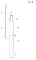
- FIG. 8 is a schematic drawing illustrating a lower push protrusion, a middle push protrusion, and an upper push protrusion corresponding with a first open button, a second open button, and a hidden button, when the slide part is closed with respect to the main body in the slide type mobile terminal of FIG. 7 .
- FIG. 9 is a schematic drawing illustrating the lower push protrusion and the middle push protrusion corresponding with the second open button and the hidden button, as the slide part is opened with respect to the main body in the slide type mobile terminal of FIG. 7 .
- FIG. 10 is an exploded perspective view of a slide type mobile terminal using a slide hinge according to yet another embodiment of the present invention.
- FIG. 11 is a schematic drawing illustrating a lower push protrusion and an upper push protrusion corresponding with an open button and a hidden button, when the slide part is closed with respect to the main body in the slide type mobile terminal of FIG. 10 .
- FIG. 12 is a schematic drawing illustrating the lower push protrusion corresponding with the hidden button, when the slide part is opened with respect to the main body in the slide type mobile terminal of FIG. 10 .
- FIG. 1 is an exploded view of a slide type mobile terminal according to an embodiment of the present invention.
- a slide type mobile terminal as illustrated in FIG. 1 , comprises a slide part 10 having a display (not shown), a main body 30 having buttons 31 and joined to the slide part 10 , and push protrusions 51 , 53 formed on the lower surface of the slide part 10 .
- the buttons 31 comprise an open button 311 and a hidden button 313 .
- a display 11 On one surface of the slide part 10 , although not shown, is formed a display 11 , and on the other surface are formed push protrusions 51 , 53 and slide grooves 15 .
- the slide part 10 is joined slidably to the upper surface of the main body 30 and can be displaced a predetermined distance by the slide grooves 15 and the slide guides 33 .
- the slide guides 33 formed on the upper surface of the main body 30 are inserted into the slide grooves 15 .
- the slide grooves 15 and the slide guides 33 allow sliding motion of the slide part 10 . Accordingly, the slide part 10 moves up and down so that it can expose or cover the open button 311 .
- the slide grooves 15 may be formed on one surface of the main body 30 , in which case the slide guides 33 would be formed on the slide part 10 .
- the slide grooves 15 and the slide guides 33 are made from plastic resin or light metals, so the elasticity of the plastic resin or the light metals allows the displacement of the slide part 10 .
- a buffer made from injection-molded plastic, etc. is positioned at the joining area between the slide grooves 15 and the slide guides 33 , and this buffer may also allow displacement of the slide part 10 .
- the push protrusions 51 , 53 comprise an upper push protrusion 53 and a lower push protrusion 51 , where the upper push protrusion 53 is positioned in the middle area of the slide part 10 and the lower push protrusion 51 is positioned in the lower area of the slide part 10 .
- the upper push protrusion 53 and the lower push protrusion 51 correspond respectively with the open button 311 and the hidden button 313 when the slide part 10 is closed with respect to the main body 30 .
- the vertical distance between the upper push protrusion 53 and the lower push protrusion 51 is equal to the distance between the open button 311 and the hidden button 313 .
- the lower and upper push protrusion 51 , 53 move due to the displacement of the slide part 10 and apply pressure on the open button 311 or the hidden button 313 , so that a function of the button 31 or the hidden button 313 is executed. Also, even when the slide part 10 is open with respect to the main body, the lower push protrusion 51 applies pressure on the hidden button 313 so that the function of the hidden button 313 may be executed.
- a slide type mobile terminal if a portion of the slide part 10 is pressed while the slide part 10 is closed, the open button 311 or the hidden button 313 , on which pressure is applied by the lower and upper push protrusions 51 , 53 , performs the role of function keys, and obsoletes function keys disposed on the upper surface of the slide part 10 .
- the open button 311 or the hidden button 313 on which pressure is applied by the lower and upper push protrusions 51 , 53 , performs the role of function keys, and obsoletes function keys disposed on the upper surface of the slide part 10 .
- it becomes convenient to use the mobile terminal and various function keys may be provided, because particular functions of the terminal can be executed by the mere push of the lower or middle portion of the slide part 10 while the slide part 10 is closed.
- buttons 31 comprising an open button 31 , which is exposed to the exterior when the slide part 10 slides upward, and a hidden button 313 , which is not exposed to the exterior, slide guides 33 formed on one side of the main body 30 , an antenna 37 , and a battery 39 .
- the buttons 31 comprise an open button 311 , which is made open when the slide part 10 is raised, and a hidden button 313 positioned between the slide guides 33 .
- the hidden button 313 in its entirety is always covered by the slide part 10 , and contacts the lower push protrusion 51 , when the slide part is closed, and the upper push protrusion 53 , when the slide part is open. Pressure is applied on the hidden button 313 , when the slide part 10 is displaced, by the upper or lower push protrusion 51 , 53 to execute a particular function. For example, such functions as the play function of audio files or the play function of video media may be executed.
- the hidden button 313 itself may execute different functions depending on whether the slide part is open or closed.
- the open button 311 may execute different functions depending on whether the slide part 10 is open or closed. For example, the open button 311 may execute the “0” function when the slide part 10 is open, and execute a function such as the play function of video media when the slide part 10 is closed.
- the slide guides 33 are formed on the upper surface of the main body 30 , and the slide grooves 15 are inserted to allow up and down motion of the slide part 10 . Also, the slide guides 33 join the slide grooves 15 to allow the displacement of the slide part 10 .
- FIG. 2 is a schematic drawing illustrating the lower push protrusion 51 and the upper push protrusion 53 corresponding with the open button 311 and the hidden button 313 , when the slide part 10 is closed with respect to the main body 30 in the slide type mobile terminal of FIG. 1
- FIG. 3 is a schematic drawing illustrating the lower push protrusion 51 corresponding with the hidden button 313 , as the slide part 10 is opened with respect to the main body 30 in the slide type mobile terminal of FIG. 1 .
- the slide part 10 When the slide part 10 is closed with respect to the main body 30 , as shown in FIG. 2 , the lower push protrusion 51 is above the open button 311 or is in contact with the open button 311 . Then, when pressure is applied on the lower end of the slide part 10 , the slide part 10 is displaced by the offset provided by the slide grooves 15 and the slide guides 33 , so that the lower push protrusion 51 applies pressure on the open button 311 . Also, when pressure is applied on the middle portion of the slide part 10 , the slide part 10 is displaced so that the upper push protrusion 53 applies pressure on the hidden button 313 .
- the lower push protrusion 51 is in contact with the hidden button 313 or is above the hidden button 313 .
- pressing the lower end of the slide part makes the lower push protrusion 51 apply pressure on the hidden button 313 , so that the function of the hidden button 313 is executed.
- FIG. 4 is an exploded perspective view of a slide type mobile terminal according to another embodiment of the present invention.
- FIG. 5 is a schematic drawing illustrating a lower push protrusion 51 , a middle push protrusion 55 , and an upper push protrusion 53 corresponding with an open button 311 , a lower hidden button 313 b , and an upper hidden button 313 a , when the slide part 10 is closed with respect to the main body 30 in the slide type mobile terminal of FIG. 4
- FIG. 6 is a schematic drawing illustrating the lower push protrusion 51 and the middle push protrusion 55 corresponding with the lower hidden button 313 b and the upper hidden button 313 a , as the slide part 10 is opened with respect to the main body 30 .
- the lower push protrusion 51 On the back face of the slide part 10 are formed the lower push protrusion 51 , middle push protrusion 55 and upper push protrusion 53 in equal or substantially equal intervals.
- the open button 311 On the top face of the main body 30 , as shown in FIG. 5 , are positioned the open button 311 , the lower hidden button 313 b , and the upper hidden button 313 a , corresponding respectively to the push protrusions 51 , 55 , 53 .
- pressing the middle portion of the slide part 10 makes the three push protrusions 51 , 53 , 55 apply pressure on the hidden buttons 313 a , 313 b and open button 311 simultaneously to execute function B. Further, when pressure is applied on the top portion of the slide part 10 , the upper push protrusion 53 applies pressure on the upper hidden button 313 a so that function C of the upper hidden button 313 a is executed.
- applying pressure on the lower end of the slide part 10 may make the lower push protrusion 51 apply pressure on the lower hidden button 313 b to execute function B, and applying pressure on the middle portion makes the middle push protrusion 55 apply pressure on the upper hidden button 313 a to execute function C.
- the functions A to C may be varied.
- the function A may be to lower the volume
- function B to play a video medium
- the function C may be to increase the volume, although they are not limited to the above.
- the open button 311 may have various functions depending on whether the slide part 10 is open or closed.
- the hidden buttons 313 a , 313 b may provide play and stop functions for an audio file when the slide part 10 is closed and provide phone number search and phone call functions when the slide part 10 is open.
- the invention is not limited to the above, and various functions for the open button and hidden button may be provided as necessary.
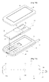
- FIG. 7 is an exploded perspective view of a slide type mobile terminal according to still another embodiment of the present invention.
- FIG. 8 is a schematic drawing illustrating a lower push protrusion 51 , a middle push protrusion 55 , and an upper push protrusion 53 corresponding with a first open button 311 a , a second open button 311 b , and a hidden button 313 , when the slide part 10 is closed with respect to the main body 30 in the slide type mobile terminal of FIG. 7
- FIG. 9 is a schematic drawing illustrating the lower push protrusion 51 and the middle push protrusion 55 corresponding with the second open button 311 b and the hidden button 313 , as the slide part 10 is opened with respect to the main body 30 in the slide type mobile terminal of FIG. 7 .
- the lower push protrusion 51 , middle push protrusion 55 and upper push protrusion 53 are placed on the back face of the slide part 10 in equal or almost equal intervals, and as shown in FIG. 8 , correspond respectively with the first open button 311 a , second open button 311 b and hidden button 313 when the slide part 10 is closed.
- applying pressure on the lower end of the slide part 10 makes the lower push protrusion 51 apply pressure on the first open button 311 a to execute function A.
- pressing the middle portion of the slide part 10 makes the three push protrusions 51 , 53 , 55 apply pressure on the open buttons 311 a , 311 b and the hidden button 313 simultaneously to execute function B.
- the upper push protrusion 53 applies pressure on the upper hidden button 313 so that function C is executed.
- applying pressure on the lower end of the slide part 10 may make the lower push protrusion 51 apply pressure on the second open button 311 b to execute function B, and applying pressure on the middle portion makes the middle push protrusion 55 apply pressure on the hidden button 313 to execute function C.
- the first and second open buttons 311 a , 311 b may provide different functions depending on whether the slide part 10 is open or closed.
- the hidden button 313 may also provide different functions depending on whether the slide part 10 is open or closed.
- FIG. 10 is an exploded perspective view of a slide type mobile terminal using a slide hinge according to yet another embodiment of the present invention.
- the slide part 10 and main body 30 of the slide type mobile terminal illustrated in FIG. 10 join each other by means of a slide hinge 20 .
- the slide hinge 20 comprises a first hinge part 21 joined to the slide part 10 , and a second hinge part 23 joined to the main body 30 and into which both ends of the first hinge part 21 are inserted slidably.
- the first hinge part 21 is secured to the back face of the slide part 10 and moves with the slide part 10 up and down with respect to the second hinge part 23 .
- a portion of the first hinge part 21 is positioned over the open button 311 .
- upper and lower push protrusions 53 , 51 are formed on the back face of the first hinge part 21 (represented in dotted lines).
- the second hinge part 23 joins the first hinge part 21 and plays the role of guiding the sliding motion of the first hinge part 21 .
- the second hinge part 23 is secured to the main body groove 35 formed on a face of the main body 30 .
- the second hinge part 23 comprises a slot 24 formed longitudinally.
- the slot 24 is a groove formed to prevent the upper push protrusion 53 from being caught on the second hinge part 23 during the sliding motion of the first hinge part 21 .
- the slot 24 may take any shape, so long as it can hold the push protrusions 51 , 53 rising in cooperation with the slide part 10 .
- the upper and lower push protrusions 53 , 51 apply pressure on the hidden button 313 positioned on the main body groove 35 by the displacement provided at the joining portion between the first hinge part 21 and the second hinge part 23 .
- the hidden button 313 is formed on the main body groove 35 , and is pressed by the lower push protrusion 51 or the upper push protrusion 53 to execute a function.
- the vertical distance between the open button 311 and the hidden button 313 is equal to the distance between the upper push protrusion 53 and the lower push protrusion 51 .
- the first hinge part 21 and the second hinge part 23 are formed by a light metal or plastic, and displacement is made possible for the first hinge part 21 and the slide part 10 due to the elastic force of such light metal or plastic.
- a molded element typically made of plastic resin, etc., is positioned at the joining portion between the first hinge part 21 and the second hinge part 23 . Such a molded element reduces noise during the movement of the first hinge part 21 as well as increasing the displacement of the first hinge part 21 .
- FIG. 11 is a schematic drawing illustrating a lower push protrusion 51 and an upper push protrusion 53 corresponding with an open button 311 and a hidden button 313 when the slide part 10 is closed with respect to the main body 30 in the slide type mobile terminal of FIG. 10
- FIG. 12 is a schematic drawing illustrating the lower push protrusion 51 corresponding with the hidden button 313 when the slide part is opened with respect to the main body in the slide type mobile terminal of FIG. 10 .
- the lower push protrusion 51 and the upper push protrusion 53 correspond respectively with the open button 311 and the hidden button 313 .
- applying pressure on the lower end of the slide part 10 makes the lower push protrusion 51 apply pressure on the open button 311 to execute function A
- pressing the middle portion makes the upper push protrusion 53 apply pressure on the hidden button 313 to execute function B.
- the hidden button 313 and the open button 311 may each provide different functions depending on whether the slide part 10 is open or closed.
- the invention can provide a slide type mobile terminal which has a bigger display and offers convenience of operation.
- the present invention can also provide a slide type mobile terminal which has various functional buttons.
Abstract
Description
Claims (9)
Applications Claiming Priority (3)
| Application Number | Priority Date | Filing Date | Title |
|---|---|---|---|
| KR1020050083174A KR100810763B1 (en) | 2005-09-07 | 2005-09-07 | Slide Type Mobile Terminal |
| KR10-2005-0083174 | 2005-09-07 | ||
| PCT/KR2005/004397 WO2007029904A1 (en) | 2005-09-07 | 2005-12-20 | Slide type mobile terminal |
Publications (2)
| Publication Number | Publication Date |
|---|---|
| US20090227300A1 US20090227300A1 (en) | 2009-09-10 |
| US8046035B2 true US8046035B2 (en) | 2011-10-25 |
Family
ID=37836002
Family Applications (1)
| Application Number | Title | Priority Date | Filing Date |
|---|---|---|---|
| US11/991,545 Expired - Fee Related US8046035B2 (en) | 2005-09-07 | 2005-12-20 | Slide type mobile terminal including a plurality of push protrusion |
Country Status (5)
| Country | Link |
|---|---|
| US (1) | US8046035B2 (en) |
| EP (1) | EP1922819B1 (en) |
| KR (1) | KR100810763B1 (en) |
| CN (1) | CN101258688A (en) |
| WO (1) | WO2007029904A1 (en) |
Cited By (1)
| Publication number | Priority date | Publication date | Assignee | Title |
|---|---|---|---|---|
| US20100226080A1 (en) * | 2007-10-26 | 2010-09-09 | Takashi Tsuchida | Slide device and electronic device using slide device |
Families Citing this family (7)
| Publication number | Priority date | Publication date | Assignee | Title |
|---|---|---|---|---|
| KR101137634B1 (en) * | 2006-03-24 | 2012-04-19 | 엘지전자 주식회사 | Portable terminal |
| KR101326648B1 (en) * | 2006-11-27 | 2013-11-08 | 엘지전자 주식회사 | Wireless communication terminal |
| DE102007059463B4 (en) * | 2007-12-11 | 2012-11-08 | Lumberg Connect Gmbh | Mobile communication device |
| US8121659B2 (en) * | 2007-12-20 | 2012-02-21 | Nokia Corporation | Slide mechanism |
| EP2093979A1 (en) * | 2008-02-19 | 2009-08-26 | Research In Motion Limited | Multi-function slide mechanism for a mobile communication device |
| US8489141B2 (en) * | 2008-06-27 | 2013-07-16 | Kyocera Corporation | Portable electronic apparatus |
| JP6587918B2 (en) * | 2015-11-27 | 2019-10-09 | 京セラ株式会社 | Electronic device, electronic device control method, electronic device control apparatus, control program, and electronic device system |
Citations (11)
| Publication number | Priority date | Publication date | Assignee | Title |
|---|---|---|---|---|
| KR20040012329A (en) | 2002-08-02 | 2004-02-11 | 엘지전자 주식회사 | Side batten structure for mobile-phone |
| CN1500312A (en) | 2001-04-04 | 2004-05-26 | 摩托罗拉公司 | Rotational mechanism for wireless communication device |
| CN1503541A (en) | 2002-11-19 | 2004-06-09 | ���ǵ�����ʽ���� | Sliding-type portable wireless terminal |
| US20040248621A1 (en) | 2001-09-06 | 2004-12-09 | Lennart Schon | Electronic device comprising a touch screen with special input functionality |
| US20050009572A1 (en) * | 2003-07-10 | 2005-01-13 | Lg Electronics Inc. | Open and close apparatus of slide type portable terminal |
| WO2005009010A1 (en) | 2003-07-23 | 2005-01-27 | Matsushita Electric Industrial Co., Ltd. | Folding information processor |
| KR20050100257A (en) | 2004-04-13 | 2005-10-18 | 주식회사 팬택앤큐리텔 | A position recognize structure of slide type mobile phone |
| KR20050104056A (en) | 2004-04-27 | 2005-11-02 | 주식회사 팬택앤큐리텔 | A slide type mobile phone with a gap reducing means |
| US7363066B2 (en) * | 2003-07-11 | 2008-04-22 | Lg Electronics Inc. | Slide type portable terminal |
| US7382695B2 (en) * | 2004-03-30 | 2008-06-03 | Seiko Instruments Inc. | Composite switch, and electronic equipment and electronic timepiece which possess composite switch |
| US7672700B2 (en) * | 2004-03-22 | 2010-03-02 | Kabushiki Kaisha Toshiba | Portable information terminal |
-
2005
- 2005-09-07 KR KR1020050083174A patent/KR100810763B1/en active IP Right Grant
- 2005-12-20 CN CNA2005800515187A patent/CN101258688A/en active Pending
- 2005-12-20 US US11/991,545 patent/US8046035B2/en not_active Expired - Fee Related
- 2005-12-20 EP EP05822032A patent/EP1922819B1/en not_active Expired - Fee Related
- 2005-12-20 WO PCT/KR2005/004397 patent/WO2007029904A1/en active Application Filing
Patent Citations (11)
| Publication number | Priority date | Publication date | Assignee | Title |
|---|---|---|---|---|
| CN1500312A (en) | 2001-04-04 | 2004-05-26 | 摩托罗拉公司 | Rotational mechanism for wireless communication device |
| US20040248621A1 (en) | 2001-09-06 | 2004-12-09 | Lennart Schon | Electronic device comprising a touch screen with special input functionality |
| KR20040012329A (en) | 2002-08-02 | 2004-02-11 | 엘지전자 주식회사 | Side batten structure for mobile-phone |
| CN1503541A (en) | 2002-11-19 | 2004-06-09 | ���ǵ�����ʽ���� | Sliding-type portable wireless terminal |
| US20050009572A1 (en) * | 2003-07-10 | 2005-01-13 | Lg Electronics Inc. | Open and close apparatus of slide type portable terminal |
| US7363066B2 (en) * | 2003-07-11 | 2008-04-22 | Lg Electronics Inc. | Slide type portable terminal |
| WO2005009010A1 (en) | 2003-07-23 | 2005-01-27 | Matsushita Electric Industrial Co., Ltd. | Folding information processor |
| US7672700B2 (en) * | 2004-03-22 | 2010-03-02 | Kabushiki Kaisha Toshiba | Portable information terminal |
| US7382695B2 (en) * | 2004-03-30 | 2008-06-03 | Seiko Instruments Inc. | Composite switch, and electronic equipment and electronic timepiece which possess composite switch |
| KR20050100257A (en) | 2004-04-13 | 2005-10-18 | 주식회사 팬택앤큐리텔 | A position recognize structure of slide type mobile phone |
| KR20050104056A (en) | 2004-04-27 | 2005-11-02 | 주식회사 팬택앤큐리텔 | A slide type mobile phone with a gap reducing means |
Non-Patent Citations (2)
| Title |
|---|
| Chinese Office Action dated Mar. 19, 2010 for corresponding Chinese Application No. 200580051518.7 and partial English translation thereof, pp. 1-6. |
| European Search Report dated Oct. 23, 2009 for corresponding European Application No. 05822032.8. |
Cited By (1)
| Publication number | Priority date | Publication date | Assignee | Title |
|---|---|---|---|---|
| US20100226080A1 (en) * | 2007-10-26 | 2010-09-09 | Takashi Tsuchida | Slide device and electronic device using slide device |
Also Published As
| Publication number | Publication date |
|---|---|
| EP1922819A1 (en) | 2008-05-21 |
| EP1922819B1 (en) | 2012-05-16 |
| WO2007029904A1 (en) | 2007-03-15 |
| US20090227300A1 (en) | 2009-09-10 |
| CN101258688A (en) | 2008-09-03 |
| KR100810763B1 (en) | 2008-03-07 |
| EP1922819A4 (en) | 2009-11-25 |
| KR20070028038A (en) | 2007-03-12 |
Similar Documents
| Publication | Publication Date | Title |
|---|---|---|
| US8046035B2 (en) | Slide type mobile terminal including a plurality of push protrusion | |
| US7184806B2 (en) | Sliding module for mobile terminal | |
| US8938276B2 (en) | Side sliding type mobile terminal | |
| KR100856238B1 (en) | Sliding type portable terminal | |
| EP1871076A1 (en) | Sliding module for mobile phone | |
| US20060178176A1 (en) | Terminal | |
| KR200408500Y1 (en) | Slim Sliding Hinge Module for Cellular Phone | |
| US20110237313A1 (en) | Mobile terminal apparatus | |
| EP1929640B1 (en) | Slide type mobile terminal | |
| KR100603933B1 (en) | Slim-type slide phone | |
| KR20080028252A (en) | Sliding type mobile phone and semi-automatic sliding unit thereof | |
| KR100785368B1 (en) | Multistage sliding hinge module for cellular phone | |
| KR100710319B1 (en) | Semi-auto slide module and slide phone having the slide module | |
| KR100609467B1 (en) | Slide phone | |
| KR100726469B1 (en) | Slide type mobile terminal | |
| KR100803457B1 (en) | Sliding module for double sliding-type portable communication device | |
| KR100648649B1 (en) | Slide type mobile terminal | |
| KR101604687B1 (en) | Mobile terminal | |
| WO2009072701A1 (en) | Elasticity lever mechanism for mobile phone and slid type cover opening and shutting device using the same | |
| KR20100047117A (en) | Portable terminal with spring module | |
| KR100856252B1 (en) | Portable terminal with sliding module | |
| US20070298633A1 (en) | Sliding-type portable terminal | |
| KR200350735Y1 (en) | Slide hinge of mobile terminal | |
| KR100688297B1 (en) | Personal portable device for sliding type and folder type | |
| KR100789830B1 (en) | Mobile communication device |
Legal Events
| Date | Code | Title | Description |
|---|---|---|---|
| AS | Assignment |
Owner name: KTF TECHNOLOGIES, INC., KOREA, REPUBLIC OF Free format text: ASSIGNMENT OF ASSIGNORS INTEREST;ASSIGNORS:LEE, UL-HO;KIM, YONG-JAE;REEL/FRAME:020669/0879 Effective date: 20080228 |
|
| AS | Assignment |
Owner name: KT TECH, INC., KOREA, REPUBLIC OF Free format text: CHANGE OF NAME;ASSIGNOR:KTF TECHNOLOGIES, INC.;REEL/FRAME:023311/0223 Effective date: 20040801 |
|
| ZAAA | Notice of allowance and fees due |
Free format text: ORIGINAL CODE: NOA |
|
| ZAAB | Notice of allowance mailed |
Free format text: ORIGINAL CODE: MN/=. |
|
| STCF | Information on status: patent grant |
Free format text: PATENTED CASE |
|
| AS | Assignment |
Owner name: KT CORPORATION, KOREA, REPUBLIC OF Free format text: ASSIGNMENT OF ASSIGNORS INTEREST;ASSIGNOR:KT TECH, INC.;REEL/FRAME:029509/0771 Effective date: 20121218 |
|
| FEPP | Fee payment procedure |
Free format text: PAYOR NUMBER ASSIGNED (ORIGINAL EVENT CODE: ASPN); ENTITY STATUS OF PATENT OWNER: LARGE ENTITY |
|
| FPAY | Fee payment |
Year of fee payment: 4 |
|
| MAFP | Maintenance fee payment |
Free format text: PAYMENT OF MAINTENANCE FEE, 8TH YEAR, LARGE ENTITY (ORIGINAL EVENT CODE: M1552); ENTITY STATUS OF PATENT OWNER: LARGE ENTITY Year of fee payment: 8 |
|
| FEPP | Fee payment procedure |
Free format text: MAINTENANCE FEE REMINDER MAILED (ORIGINAL EVENT CODE: REM.); ENTITY STATUS OF PATENT OWNER: LARGE ENTITY |
|
| LAPS | Lapse for failure to pay maintenance fees |
Free format text: PATENT EXPIRED FOR FAILURE TO PAY MAINTENANCE FEES (ORIGINAL EVENT CODE: EXP.); ENTITY STATUS OF PATENT OWNER: LARGE ENTITY |
|
| STCH | Information on status: patent discontinuation |
Free format text: PATENT EXPIRED DUE TO NONPAYMENT OF MAINTENANCE FEES UNDER 37 CFR 1.362 |
|
| FP | Lapsed due to failure to pay maintenance fee |
Effective date: 20231025 |