US8064093B2 - Method and apparatus to digitally whiteout mistakes on a printed form - Google Patents
Method and apparatus to digitally whiteout mistakes on a printed form Download PDFInfo
- Publication number
- US8064093B2 US8064093B2 US12/872,949 US87294910A US8064093B2 US 8064093 B2 US8064093 B2 US 8064093B2 US 87294910 A US87294910 A US 87294910A US 8064093 B2 US8064093 B2 US 8064093B2
- Authority
- US
- United States
- Prior art keywords
- user
- digital image
- image
- code
- create
- Prior art date
- Legal status (The legal status is an assumption and is not a legal conclusion. Google has not performed a legal analysis and makes no representation as to the accuracy of the status listed.)
- Active
Links
- 238000000034 method Methods 0.000 title claims abstract description 44
- 241000276489 Merlangius merlangus Species 0.000 claims description 7
- 238000003708 edge detection Methods 0.000 claims description 5
- 238000012937 correction Methods 0.000 abstract description 5
- 230000006870 function Effects 0.000 description 8
- 238000012552 review Methods 0.000 description 5
- 238000004891 communication Methods 0.000 description 3
- 230000007423 decrease Effects 0.000 description 1
- 238000011161 development Methods 0.000 description 1
- 230000000694 effects Effects 0.000 description 1
- 239000007788 liquid Substances 0.000 description 1
- 230000003287 optical effect Effects 0.000 description 1
- 238000012545 processing Methods 0.000 description 1
- 238000011160 research Methods 0.000 description 1
- 230000000007 visual effect Effects 0.000 description 1
- 230000003442 weekly effect Effects 0.000 description 1
Images


Classifications
-
- H—ELECTRICITY
- H04—ELECTRIC COMMUNICATION TECHNIQUE
- H04N—PICTORIAL COMMUNICATION, e.g. TELEVISION
- H04N1/00—Scanning, transmission or reproduction of documents or the like, e.g. facsimile transmission; Details thereof
- H04N1/38—Circuits or arrangements for blanking or otherwise eliminating unwanted parts of pictures
Definitions
- the present invention relates generally to pre-printed forms and, more particularly, to computer software for correcting errors made while filling out pre-printed forms.
- a method and apparatus enables users to make corrections to printed forms.
- the printed form is scanned and displayed to the user on a display of a computer arrangement.
- the user interacts with the computer arrangement via user input devices to select one or more regions of the printed form to be corrected.
- the selected regions are digitally whited-out to create a corrected image that can be output to a printer.
- An exemplary method comprises scanning the printed form to create a first digital image of the printed form, displaying the first digital image of the printed form to the user on a display, receiving user input indicating one or more selected regions of the printed form, digitally whiting out the selected regions of the printed form to create a corrected form, and outputting the corrected form to an output device.
- An exemplary computer arrangement comprises a display and a processor connected to the display.
- the processor is configured to output a first digital image of the printed form to a display, receive user selection input indicating one or more selected regions of the printed form, digitally white out the selected regions of the printed form to create a corrected image; and output the corrected image to an output device.
- An exemplary computer readable media contains code for outputting a first digital image of the printed form to a display of said computer, code for receiving user selection input indicating one or more selected regions of the printed form, code for digitally whiting out the selected regions of the printed form to create a corrected image; and code for outputting the corrected image to an output device connected to the computer.
- FIG. 1 illustrates an exemplary computer system
- FIG. 2 illustrates an exemplary computer
- FIGS. 3A-3B illustrate graphical interfaces associated with a white-out application
- FIG. 4 illustrates a portion of a printed form
- FIG. 5 illustrates a method implemented by an exemplary white-out application.
- FIG. 1 illustrates an exemplary computer system 10 for implementing the present invention.
- Computer system 10 comprises a computer 12 , a scanner 14 , and a printer 16 .
- the computer 12 may comprise any conventional desktop, laptop, or notebook computer having a display 22 , keyboard 24 , mouse 26 and/or other user input device.
- the scanner 14 and printer 16 connect to the computer 12 through wired or wireless links. Though shown separately, the scanner 14 and printer 16 may be incorporated into a single unit.
- the scanner 14 scans printed forms or other documents and generates digital images that can be stored, transmitted, or displayed by the computer 12 .
- a digital whiteout application is installed on the computer 12 that enables users to make corrections to digital copies of scanned forms.
- the digitally corrected copies of scanned forms can be output to the printer 16 which may, for example, comprise a laser printer or inkjet printer.
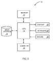
- FIG. 2 illustrates an exemplary computer 12 .
- the computer 12 comprises a central processing unit (CPU) 18 and memory 20 arranged to execute software, such as the digital whiteout application described below.
- Display 22 provides a visual output for viewing by a user.
- User input devices such as keyboard 24 and mouse 26 , enable a user to input commands and data into the computer 12 .
- application programs may display a graphical user interface on the computer display 22 , and the user may interact with the graphical user interface using the keyboard 24 , mouse 26 , and/or other user input devices.
- Computer 12 may further include a mass storage device 28 such as a magnetic disk drive or optical disk drive, and a communications interface 30 for communicating with remote devices over a communication network.
- the communication interface 30 may, for example, comprise an Ethernet interface, a serial interface (e.g., USB), a parallel interface (e.g. Firewire), or a radio interface (e.g., Bluetooth, WiFi).
- the digital whiteout application is stored in memory 20 of the computer 12 .
- the digital whiteout application allows users to digitally whiteout mistakes made while completing printed forms.
- the digital whiteout application includes a simple graphical user interface to make it easy for a novice user to correct mistakes in a printed form.
- the whiteout process can be divided into three simple processes, the scanning process, the selection process, and the final review process.
- the user first scans the form to create a digital image of the form (the scanning process), uses simple selection tools to select regions that are to be whited out (the selection process), and outputs the corrected form to a printer or other output device (the final review process).
- the user first scans the printed form to create a digital bitmap image of the form.
- the digital image may be in any file format, such as tiff, gif, bmp, etc.
- the printed form can be scanned using scanning software that is packaged with the scanner.
- the digital image can be stored in the computer file system and opened in the digital whiteout application.
- the digital whiteout application may control the scanning process to acquire and display the digital image. After the digital image is scanned, it is displayed to the user in a graphical user interface associated with the digital whiteout application.
- FIGS. 3A and 3B illustrate a graphical user interface 100 associated with the digital whiteout application in one exemplary embodiment.
- FIG. 3A shows the interface 100 during the selection process
- FIG. 3B shows the interface 100 during the final review process.
- the graphical user interface 100 may be displayed in a conventional window that includes a window frame, title bar, menu bars, tool bars, status bars, resizing handles, etc. As known in the art, the window can be moved and resized as desired.
- the graphical user interface 100 divides the display area of the window into three panels: a display panel 102 , a side panel 104 , and a bottom panel 106 .
- the display panel 102 is used to display the digital image of the scanned form to the user.
- the user can manipulate the image in the preview area 108 and select desired regions to be whited out.
- the side panel 104 contains selection tools during the selection process ( FIG. 3A ) and presents output options to the user during the final review process ( FIG. 3B ).
- the bottom panel displays may contain command buttons and/or navigation controls depending on the context.
- FIG. 3A illustrates the graphical user interface as it might appear during the selection process.
- Digital images of scanned forms are displayed to the user in a preview area 108 in the display panel 102 .
- a zoom control 110 is disposed below the preview area 108 .
- the zoom control 110 allows the user to zoom the image in or out.
- the zoom control 110 comprises a slide control. Sliding the control 110 to the right enlarges the image, and sliding the control 110 to the left diminishes the image. The user may also pan the image by clicking and dragging on the image.
- the side panel 104 includes a collection of selection tools for the user.
- the selection tools include a rectangle tool 112 and an eraser tool 114 , although other selection tools in addition to or in place of these tools could be used.
- the selection tools are used by a user to select regions in a scanned image that are to be digitally whited out.
- the rectangle tool 112 allows the user to draw a rectangle around a selected region.
- the rectangle tool 112 is particularly useful for selecting large areas.
- the eraser tool 114 is a specialized region selection tool that allows the user to select small areas the size of the eraser 114 .
- the selected regions could be of any shape, such as circular or rectangular.
- the eraser tool 114 includes a size control 116 that allows the user to change the size of the eraser.
- the eraser tool 114 in the exemplary embodiment includes a slide control. Sliding the size control 116 to the right increases the size of the eraser 114 , and sliding the size control 116 to the left decreases the size of the eraser 114 .
- the bottom panel 106 includes a NEXT button 118 . Selection of the NEXT button 118 by the user indicates that the user has completed his or her selections and ends the selection process. When the NEXT button is selected, the interface 100 shown in FIG. 3B is displayed.
- FIG. 3B illustrates the graphical user interface 100 during the final review process.
- the printed form may be rescanned at a high resolution (e.g., 300 dpi or greater) to create a high resolution digital image.
- the selected regions are digitally whited out and the resulting image is displayed to the user in the preview window 108 .
- the display panel 102 includes a zoom control 110 as previously described to enable the user to zoom the image. As noted before, the use may also pan the image by clicking on the image and dragging the image.
- the side panel 104 contains a collection of command buttons providing different options to the user. In the exemplary embodiment shown in FIG.
- the command buttons include a PRINT button 120 , SAVE AS PDF button 122 , SAVE AS HTML button 124 , SAVE AS RTF button 126 , and RETRY button 128 .
- Selection of the PRINT button causes the displayed image to be output to a printer 16 .
- the three SAVE AS buttons 122 , 124 , 126 save the displayed image to the computer file system in the selected format.
- Selection of the RETRY button causes the digital whiteout application to return to the selection process.
- a second PRINT button 130 is displayed to the user in the bottom panel 106 .
- the PRINT button 130 in the bottom panel 106 has the same function as the PRINT button 120 in the side panel 104 .
- the digital whiteout application may include an expansion function to expand a selection made by the user.
- the expansion function is useful in cases where the user selection does not fully contain the undesired markings on a printed form as shown in FIG. 4 .
- FIG. 4 illustrates a printed form 300 with a user selection 302 containing an undesired mark 304 , which in this example is the name John Doe. A small portion 306 of the undesired mark extends beyond the boundary of the user-selected region.
- the expansion function may be invoked to expand the user selection to more fully contain the undesired marking. More particularly, the expansion function may implement an edge detection algorithm or nearest-pixel algorithm that effectively traces around the edge of the undesired marking.
- the area traced by the edge detection algorithm is added to the user-selected region to create an expanded region.
- the digital whiteout operation is then performed over the expanded region.
- the user may have the option of enabling/disabling the expansion function.
- an enable intelligent selection check box 115 may be displayed to the user as shown in FIG. 3A for enabling and disabling the expansion function.
- FIG. 5 illustrates an exemplary method 200 implemented by the digital whiteout application.
- the digital whiteout application may control the scanner 14 to scan a printed form to be corrected (block 202 ).
- the application acquires image data from the scanner and displays the digital image of the printed form to the user (block 204 ).
- the initial image acquired for the selection process may be a low resolution image (e.g., 72 dpi) that still enables the user to see the image clearly and to select the desired regions to be corrected.
- Using a low resolution image for the selection process allows the user to more quickly make his or her selections without having to wait for a high resolution scan to be completed.
- the application receives input indicating user selection of one or more regions of the digital image to be corrected (block 206 ).
- the user may use the rectangle tool 112 to draw a rectangle around a desired region, or may use the eraser tool 114 to designate smaller regions.
- the user may zoom and pan the image.
- the application determines whether the intelligent selection option is enabled (block 208 ). If so, the expansion function in the application is called to expand or extend the user-selected area (block 210 ). As previously indicated, the extended region is added to the user-selected region.
- the application controls the scanner to rescan the form (block 214 ) at a high resolution (e.g. 300 dpi or greater).
- the selected regions may optionally be scaled if the preview image is a low resolution image and the final output image is a high resolution image (block 212 ).
- the pixel values contained within the selected region are set to white (255, 255, 255) (block 216 ).
- the second scanning process can be eliminated in some embodiments if the original scan is at a high resolution.
- the corrected image is output to an output device or saved to the computer file system (block 218 ).
- the digital whiteout application provides an easy and convenient method for a novice user to correct mistakes made while completing a printed form.
- the digital whiteout application can restore forms on which mistakes have been made without damaging the document.
- the restored form will be virtually indistinguishable from the original form. Users may find the result more acceptable than either marking through mistakes or using liquid whiteout or correction tape.
Abstract
Description
Claims (17)
Priority Applications (1)
| Application Number | Priority Date | Filing Date | Title |
|---|---|---|---|
| US12/872,949 US8064093B2 (en) | 2007-05-01 | 2010-08-31 | Method and apparatus to digitally whiteout mistakes on a printed form |
Applications Claiming Priority (2)
| Application Number | Priority Date | Filing Date | Title |
|---|---|---|---|
| US11/742,669 US7880921B2 (en) | 2007-05-01 | 2007-05-01 | Method and apparatus to digitally whiteout mistakes on a printed form |
| US12/872,949 US8064093B2 (en) | 2007-05-01 | 2010-08-31 | Method and apparatus to digitally whiteout mistakes on a printed form |
Related Parent Applications (1)
| Application Number | Title | Priority Date | Filing Date |
|---|---|---|---|
| US11/742,669 Continuation US7880921B2 (en) | 2007-05-01 | 2007-05-01 | Method and apparatus to digitally whiteout mistakes on a printed form |
Publications (2)
| Publication Number | Publication Date |
|---|---|
| US20100325538A1 US20100325538A1 (en) | 2010-12-23 |
| US8064093B2 true US8064093B2 (en) | 2011-11-22 |
Family
ID=39939307
Family Applications (2)
| Application Number | Title | Priority Date | Filing Date |
|---|---|---|---|
| US11/742,669 Active 2029-03-31 US7880921B2 (en) | 2007-05-01 | 2007-05-01 | Method and apparatus to digitally whiteout mistakes on a printed form |
| US12/872,949 Active US8064093B2 (en) | 2007-05-01 | 2010-08-31 | Method and apparatus to digitally whiteout mistakes on a printed form |
Family Applications Before (1)
| Application Number | Title | Priority Date | Filing Date |
|---|---|---|---|
| US11/742,669 Active 2029-03-31 US7880921B2 (en) | 2007-05-01 | 2007-05-01 | Method and apparatus to digitally whiteout mistakes on a printed form |
Country Status (1)
| Country | Link |
|---|---|
| US (2) | US7880921B2 (en) |
Families Citing this family (66)
| Publication number | Priority date | Publication date | Assignee | Title |
|---|---|---|---|---|
| US7962495B2 (en) | 2006-11-20 | 2011-06-14 | Palantir Technologies, Inc. | Creating data in a data store using a dynamic ontology |
| US8515912B2 (en) | 2010-07-15 | 2013-08-20 | Palantir Technologies, Inc. | Sharing and deconflicting data changes in a multimaster database system |
| US8930331B2 (en) | 2007-02-21 | 2015-01-06 | Palantir Technologies | Providing unique views of data based on changes or rules |
| US9348499B2 (en) * | 2008-09-15 | 2016-05-24 | Palantir Technologies, Inc. | Sharing objects that rely on local resources with outside servers |
| US20100118350A1 (en) * | 2008-11-12 | 2010-05-13 | Xerox Corporation | Method of segmenting a document image in digital image scanning |
| JP2011035580A (en) * | 2009-07-31 | 2011-02-17 | Brother Industries Ltd | Image read device, communication device and image communication system |
| US20110102829A1 (en) * | 2009-10-30 | 2011-05-05 | Jourdan Arlene T | Image size warning |
| CN102736869A (en) * | 2011-01-21 | 2012-10-17 | 精工爱普生株式会社 | Print control server, print controlling method, and print control program |
| US8799240B2 (en) | 2011-06-23 | 2014-08-05 | Palantir Technologies, Inc. | System and method for investigating large amounts of data |
| US8732574B2 (en) | 2011-08-25 | 2014-05-20 | Palantir Technologies, Inc. | System and method for parameterizing documents for automatic workflow generation |
| US9798768B2 (en) | 2012-09-10 | 2017-10-24 | Palantir Technologies, Inc. | Search around visual queries |
| US9348677B2 (en) | 2012-10-22 | 2016-05-24 | Palantir Technologies Inc. | System and method for batch evaluation programs |
| US9081975B2 (en) | 2012-10-22 | 2015-07-14 | Palantir Technologies, Inc. | Sharing information between nexuses that use different classification schemes for information access control |
| US9501761B2 (en) | 2012-11-05 | 2016-11-22 | Palantir Technologies, Inc. | System and method for sharing investigation results |
| US10140664B2 (en) | 2013-03-14 | 2018-11-27 | Palantir Technologies Inc. | Resolving similar entities from a transaction database |
| US8924388B2 (en) | 2013-03-15 | 2014-12-30 | Palantir Technologies Inc. | Computer-implemented systems and methods for comparing and associating objects |
| US8868486B2 (en) | 2013-03-15 | 2014-10-21 | Palantir Technologies Inc. | Time-sensitive cube |
| US8909656B2 (en) | 2013-03-15 | 2014-12-09 | Palantir Technologies Inc. | Filter chains with associated multipath views for exploring large data sets |
| US8799799B1 (en) | 2013-05-07 | 2014-08-05 | Palantir Technologies Inc. | Interactive geospatial map |
| US9565152B2 (en) | 2013-08-08 | 2017-02-07 | Palantir Technologies Inc. | Cable reader labeling |
| US8938686B1 (en) | 2013-10-03 | 2015-01-20 | Palantir Technologies Inc. | Systems and methods for analyzing performance of an entity |
| US9105000B1 (en) | 2013-12-10 | 2015-08-11 | Palantir Technologies Inc. | Aggregating data from a plurality of data sources |
| US10579647B1 (en) | 2013-12-16 | 2020-03-03 | Palantir Technologies Inc. | Methods and systems for analyzing entity performance |
| US8924429B1 (en) | 2014-03-18 | 2014-12-30 | Palantir Technologies Inc. | Determining and extracting changed data from a data source |
| US9836580B2 (en) | 2014-03-21 | 2017-12-05 | Palantir Technologies Inc. | Provider portal |
| US9454281B2 (en) | 2014-09-03 | 2016-09-27 | Palantir Technologies Inc. | System for providing dynamic linked panels in user interface |
| US9767172B2 (en) | 2014-10-03 | 2017-09-19 | Palantir Technologies Inc. | Data aggregation and analysis system |
| US9501851B2 (en) | 2014-10-03 | 2016-11-22 | Palantir Technologies Inc. | Time-series analysis system |
| US9984133B2 (en) | 2014-10-16 | 2018-05-29 | Palantir Technologies Inc. | Schematic and database linking system |
| EP3032441A2 (en) | 2014-12-08 | 2016-06-15 | Palantir Technologies, Inc. | Distributed acoustic sensing data analysis system |
| US9483546B2 (en) | 2014-12-15 | 2016-11-01 | Palantir Technologies Inc. | System and method for associating related records to common entities across multiple lists |
| US11302426B1 (en) | 2015-01-02 | 2022-04-12 | Palantir Technologies Inc. | Unified data interface and system |
| US10803106B1 (en) | 2015-02-24 | 2020-10-13 | Palantir Technologies Inc. | System with methodology for dynamic modular ontology |
| EP3611632A1 (en) | 2015-03-16 | 2020-02-19 | Palantir Technologies Inc. | Displaying attribute and event data along paths |
| US9348880B1 (en) | 2015-04-01 | 2016-05-24 | Palantir Technologies, Inc. | Federated search of multiple sources with conflict resolution |
| US10103953B1 (en) | 2015-05-12 | 2018-10-16 | Palantir Technologies Inc. | Methods and systems for analyzing entity performance |
| US10628834B1 (en) | 2015-06-16 | 2020-04-21 | Palantir Technologies Inc. | Fraud lead detection system for efficiently processing database-stored data and automatically generating natural language explanatory information of system results for display in interactive user interfaces |
| US9418337B1 (en) | 2015-07-21 | 2016-08-16 | Palantir Technologies Inc. | Systems and models for data analytics |
| US9392008B1 (en) | 2015-07-23 | 2016-07-12 | Palantir Technologies Inc. | Systems and methods for identifying information related to payment card breaches |
| US9600146B2 (en) | 2015-08-17 | 2017-03-21 | Palantir Technologies Inc. | Interactive geospatial map |
| US10706434B1 (en) | 2015-09-01 | 2020-07-07 | Palantir Technologies Inc. | Methods and systems for determining location information |
| US9984428B2 (en) | 2015-09-04 | 2018-05-29 | Palantir Technologies Inc. | Systems and methods for structuring data from unstructured electronic data files |
| US20170092013A1 (en) * | 2015-09-26 | 2017-03-30 | Boston Scientific Scimed Inc. | Adjustable depth anatomical shell editing |
| EP3353753A1 (en) | 2015-09-26 | 2018-08-01 | Boston Scientific Scimed Inc. | Systems and methods for anatomical shell editing |
| CN105302437B (en) * | 2015-10-13 | 2019-10-29 | 联想(北京)有限公司 | A kind of erasing rubber size switching method and electronic equipment |
| US9760556B1 (en) | 2015-12-11 | 2017-09-12 | Palantir Technologies Inc. | Systems and methods for annotating and linking electronic documents |
| US9514414B1 (en) | 2015-12-11 | 2016-12-06 | Palantir Technologies Inc. | Systems and methods for identifying and categorizing electronic documents through machine learning |
| US9542446B1 (en) | 2015-12-17 | 2017-01-10 | Palantir Technologies, Inc. | Automatic generation of composite datasets based on hierarchical fields |
| US10089289B2 (en) | 2015-12-29 | 2018-10-02 | Palantir Technologies Inc. | Real-time document annotation |
| US9996236B1 (en) | 2015-12-29 | 2018-06-12 | Palantir Technologies Inc. | Simplified frontend processing and visualization of large datasets |
| US10248722B2 (en) | 2016-02-22 | 2019-04-02 | Palantir Technologies Inc. | Multi-language support for dynamic ontology |
| US10719188B2 (en) | 2016-07-21 | 2020-07-21 | Palantir Technologies Inc. | Cached database and synchronization system for providing dynamic linked panels in user interface |
| US10324609B2 (en) | 2016-07-21 | 2019-06-18 | Palantir Technologies Inc. | System for providing dynamic linked panels in user interface |
| US10133588B1 (en) | 2016-10-20 | 2018-11-20 | Palantir Technologies Inc. | Transforming instructions for collaborative updates |
| US10044836B2 (en) | 2016-12-19 | 2018-08-07 | Palantir Technologies Inc. | Conducting investigations under limited connectivity |
| US10216811B1 (en) | 2017-01-05 | 2019-02-26 | Palantir Technologies Inc. | Collaborating using different object models |
| US11074277B1 (en) | 2017-05-01 | 2021-07-27 | Palantir Technologies Inc. | Secure resolution of canonical entities |
| US10942947B2 (en) | 2017-07-17 | 2021-03-09 | Palantir Technologies Inc. | Systems and methods for determining relationships between datasets |
| US10482170B2 (en) * | 2017-10-17 | 2019-11-19 | Hrb Innovations, Inc. | User interface for contextual document recognition |
| US10956508B2 (en) | 2017-11-10 | 2021-03-23 | Palantir Technologies Inc. | Systems and methods for creating and managing a data integration workspace containing automatically updated data models |
| US10783162B1 (en) | 2017-12-07 | 2020-09-22 | Palantir Technologies Inc. | Workflow assistant |
| US11061874B1 (en) | 2017-12-14 | 2021-07-13 | Palantir Technologies Inc. | Systems and methods for resolving entity data across various data structures |
| US10853352B1 (en) | 2017-12-21 | 2020-12-01 | Palantir Technologies Inc. | Structured data collection, presentation, validation and workflow management |
| GB201800595D0 (en) | 2018-01-15 | 2018-02-28 | Palantir Technologies Inc | Management of software bugs in a data processing system |
| US11599369B1 (en) | 2018-03-08 | 2023-03-07 | Palantir Technologies Inc. | Graphical user interface configuration system |
| US11061542B1 (en) | 2018-06-01 | 2021-07-13 | Palantir Technologies Inc. | Systems and methods for determining and displaying optimal associations of data items |
Citations (4)
| Publication number | Priority date | Publication date | Assignee | Title |
|---|---|---|---|---|
| US5459586A (en) * | 1991-10-16 | 1995-10-17 | Fuji Xerox Co., Ltd. | Image processing system provided with image enchasing and synthesizing function |
| US5822454A (en) * | 1995-04-10 | 1998-10-13 | Rebus Technology, Inc. | System and method for automatic page registration and automatic zone detection during forms processing |
| US20030231367A1 (en) * | 2002-05-31 | 2003-12-18 | Angelica Quintana | Document image capture device with integrated document display screen |
| US7084886B2 (en) * | 2002-07-16 | 2006-08-01 | Idelix Software Inc. | Using detail-in-context lenses for accurate digital image cropping and measurement |
Family Cites Families (5)
| Publication number | Priority date | Publication date | Assignee | Title |
|---|---|---|---|---|
| US4751583A (en) * | 1984-06-04 | 1988-06-14 | Levine Alfred B | Off line photocopying system using portable electronic camera, visual previewing and image processing |
| EP0693852A3 (en) * | 1994-07-22 | 1997-05-28 | Eastman Kodak Co | Method and apparatus for applying a function to a localized area of a digital image using a window |
| US6449636B1 (en) * | 1999-09-08 | 2002-09-10 | Nortel Networks Limited | System and method for creating a dynamic data file from collected and filtered web pages |
| US6532349B1 (en) * | 2000-11-16 | 2003-03-11 | Toshiba Tec Kabushiki Kaisha | Image reading-out apparatus |
| JP3814592B2 (en) * | 2003-06-27 | 2006-08-30 | キヤノン株式会社 | Imaging apparatus and control method thereof |
-
2007
- 2007-05-01 US US11/742,669 patent/US7880921B2/en active Active
-
2010
- 2010-08-31 US US12/872,949 patent/US8064093B2/en active Active
Patent Citations (4)
| Publication number | Priority date | Publication date | Assignee | Title |
|---|---|---|---|---|
| US5459586A (en) * | 1991-10-16 | 1995-10-17 | Fuji Xerox Co., Ltd. | Image processing system provided with image enchasing and synthesizing function |
| US5822454A (en) * | 1995-04-10 | 1998-10-13 | Rebus Technology, Inc. | System and method for automatic page registration and automatic zone detection during forms processing |
| US20030231367A1 (en) * | 2002-05-31 | 2003-12-18 | Angelica Quintana | Document image capture device with integrated document display screen |
| US7084886B2 (en) * | 2002-07-16 | 2006-08-01 | Idelix Software Inc. | Using detail-in-context lenses for accurate digital image cropping and measurement |
Non-Patent Citations (1)
| Title |
|---|
| Adobe Photoshop 4.0 User Guide, Sep. 1996, pp. 6-7 and 17. * |
Also Published As
| Publication number | Publication date |
|---|---|
| US20100325538A1 (en) | 2010-12-23 |
| US20080273227A1 (en) | 2008-11-06 |
| US7880921B2 (en) | 2011-02-01 |
Similar Documents
| Publication | Publication Date | Title |
|---|---|---|
| US8064093B2 (en) | Method and apparatus to digitally whiteout mistakes on a printed form | |
| JP4083827B2 (en) | Image processing method and image processing apparatus | |
| US7483166B2 (en) | Information processing apparatus and print preview display method | |
| US8446629B2 (en) | Printer driver, image forming apparatus and print controlling method | |
| US8861022B2 (en) | Image processing apparatus with preview display function, image processing method, and image processing program | |
| EP2493170A1 (en) | Control device controlling scan operation | |
| US20060075362A1 (en) | Image processing apparatus, method, and recording medium on which program is recorded for displaying thumbnail/preview image | |
| JP7094733B2 (en) | Image processing device, program, image processing method | |
| EP2302592B1 (en) | Layout editing system, layout editing method, and image processing apparatus | |
| EP3352441A1 (en) | Scanner, scanning control program, and image file generating method | |
| US20090244570A1 (en) | Face image-output control device, method of controlling output of face image, program for controlling output of face image, and printing device | |
| US20100149557A1 (en) | Image processing apparatus and image processing method | |
| JP6917285B2 (en) | Image forming device | |
| JP4272603B2 (en) | Information processing device | |
| CN109327636B (en) | Image processing apparatus | |
| JP6714872B2 (en) | Image forming device | |
| US10768876B2 (en) | Display device, image processing apparatus, and non-transitory computer readable medium with changing process action interface based on process object selection | |
| JPH11180005A (en) | Method and apparatus for reprinting in image forming apparatus | |
| JP4501731B2 (en) | Image processing device | |
| JP4412211B2 (en) | Skew correction method, program, image processing apparatus, and image processing system | |
| JP4305343B2 (en) | Image processing device | |
| US20080238944A1 (en) | Image processing devices and methods of recording a scaled portion of an image on a recording medium | |
| JP2006137084A (en) | Printer | |
| JP7155833B2 (en) | Image processing device | |
| JP4232050B2 (en) | Tiling offset output system |
Legal Events
| Date | Code | Title | Description |
|---|---|---|---|
| STCF | Information on status: patent grant |
Free format text: PATENTED CASE |
|
| FPAY | Fee payment |
Year of fee payment: 4 |
|
| AS | Assignment |
Owner name: CHINA CITIC BANK CORPORATION LIMITED, GUANGZHOU BR Free format text: PATENT SECURITY AGREEMENT;ASSIGNOR:LEXMARK INTERNATIONAL, INC.;REEL/FRAME:046989/0396 Effective date: 20180402 |
|
| AS | Assignment |
Owner name: CHINA CITIC BANK CORPORATION LIMITED, GUANGZHOU BR Free format text: CORRECTIVE ASSIGNMENT TO CORRECT THE INCORRECT U.S. PATENT NUMBER PREVIOUSLY RECORDED AT REEL: 046989 FRAME: 0396. ASSIGNOR(S) HEREBY CONFIRMS THE PATENT SECURITY AGREEMENT;ASSIGNOR:LEXMARK INTERNATIONAL, INC.;REEL/FRAME:047760/0795 Effective date: 20180402 |
|
| MAFP | Maintenance fee payment |
Free format text: PAYMENT OF MAINTENANCE FEE, 8TH YEAR, LARGE ENTITY (ORIGINAL EVENT CODE: M1552); ENTITY STATUS OF PATENT OWNER: LARGE ENTITY Year of fee payment: 8 |
|
| FEPP | Fee payment procedure |
Free format text: MAINTENANCE FEE REMINDER MAILED (ORIGINAL EVENT CODE: REM.); ENTITY STATUS OF PATENT OWNER: LARGE ENTITY |
|
| FEPP | Fee payment procedure |
Free format text: 11.5 YR SURCHARGE- LATE PMT W/IN 6 MO, LARGE ENTITY (ORIGINAL EVENT CODE: M1556); ENTITY STATUS OF PATENT OWNER: LARGE ENTITY |
|
| MAFP | Maintenance fee payment |
Free format text: PAYMENT OF MAINTENANCE FEE, 12TH YEAR, LARGE ENTITY (ORIGINAL EVENT CODE: M1553); ENTITY STATUS OF PATENT OWNER: LARGE ENTITY Year of fee payment: 12 |
|
| AS | Assignment |
Owner name: LEXMARK INTERNATIONAL, INC., KENTUCKY Free format text: RELEASE BY SECURED PARTY;ASSIGNOR:CHINA CITIC BANK CORPORATION LIMITED, GUANGZHOU BRANCH, AS COLLATERAL AGENT;REEL/FRAME:066345/0026 Effective date: 20220713 |