US8070482B2 - Combustion control system of detection and analysis of gas or fuel oil flames using optical devices - Google Patents
Combustion control system of detection and analysis of gas or fuel oil flames using optical devices Download PDFInfo
- Publication number
- US8070482B2 US8070482B2 US12/139,657 US13965708A US8070482B2 US 8070482 B2 US8070482 B2 US 8070482B2 US 13965708 A US13965708 A US 13965708A US 8070482 B2 US8070482 B2 US 8070482B2
- Authority
- US
- United States
- Prior art keywords
- flame
- signal
- control
- combustion
- optical
- Prior art date
- Legal status (The legal status is an assumption and is not a legal conclusion. Google has not performed a legal analysis and makes no representation as to the accuracy of the status listed.)
- Expired - Fee Related
Links
Images


Classifications
-
- G—PHYSICS
- G01—MEASURING; TESTING
- G01N—INVESTIGATING OR ANALYSING MATERIALS BY DETERMINING THEIR CHEMICAL OR PHYSICAL PROPERTIES
- G01N21/00—Investigating or analysing materials by the use of optical means, i.e. using sub-millimetre waves, infrared, visible or ultraviolet light
- G01N21/62—Systems in which the material investigated is excited whereby it emits light or causes a change in wavelength of the incident light
- G01N21/71—Systems in which the material investigated is excited whereby it emits light or causes a change in wavelength of the incident light thermally excited
- G01N21/72—Systems in which the material investigated is excited whereby it emits light or causes a change in wavelength of the incident light thermally excited using flame burners
-
- F—MECHANICAL ENGINEERING; LIGHTING; HEATING; WEAPONS; BLASTING
- F23—COMBUSTION APPARATUS; COMBUSTION PROCESSES
- F23N—REGULATING OR CONTROLLING COMBUSTION
- F23N3/00—Regulating air supply or draught
- F23N3/002—Regulating air supply or draught using electronic means
-
- F—MECHANICAL ENGINEERING; LIGHTING; HEATING; WEAPONS; BLASTING
- F23—COMBUSTION APPARATUS; COMBUSTION PROCESSES
- F23N—REGULATING OR CONTROLLING COMBUSTION
- F23N5/00—Systems for controlling combustion
- F23N5/02—Systems for controlling combustion using devices responsive to thermal changes or to thermal expansion of a medium
- F23N5/08—Systems for controlling combustion using devices responsive to thermal changes or to thermal expansion of a medium using light-sensitive elements
- F23N5/082—Systems for controlling combustion using devices responsive to thermal changes or to thermal expansion of a medium using light-sensitive elements using electronic means
Definitions
- the present invention optimizes gas burner combustion using optical devices to analyze the flame.
- the optical signals are processed to diagnose the combustion state and optimize burner operations in terms of its efficiency and polluting emissions.
- CCD cameras have a linear spectral response and that this answer depends on the spectral sensitivity of the different sensors or filters for the colors of each camera individually. Additionally, they linearly depend on the incident power density and the wavelength. Finally, the spectral response is affected by noise, which can be diminished with a correct calibration. [Vora, Farell, Tietz and Brainard, (2000)].
- the HSB (Tonality, Saturation and Brightness) color model does allow this interdependence between the channels and it is very useful for procedures to recognize patterns in images. Additionally, the L*a*b* color model, which also allows us to obtain dependency between the channels, has also been studied [Ward, (2006)].
- SpectraTune is a combustion diagnosis and optimization system based on the analysis of spectral frequency, the visible phantom and the near TO GO, developed by Mark J. Khesin through the company Physical Sciences Inc. At present, the system is commercialized by GE Power Systems under the denomination “MK Optimization Combustion System”. Its design is limited to applications in power stations that use pulverized coal and its application depends on operator criteria and does not allow total automatization for burner control. Its cost is around US$ 25,000 for each Burner.
- Flame Doctor is a system that provides real time analysis for each burner of a furnace. It analyzes the individual burner performance, identifying those with low yield and provides a diagnosis that orients the necessary adjustments. Flame Doctor uses signals from optical flame sensors, which with mathematical professing tools determine the degree of deviation with respect to the optimal degree. Its application has been developed for coal combustion and its price is in the order of US$ 150,000. The mentioned technologies are oriented to large-size facilities (on 350 MW).
- Patent GB1396384 describes a sensor and a furnace control method that uses photoelectric sensors with two attachment lines to intercept the flame, producing two electrical exits or signals (x and y).
- the system consists of two tubes similar to a telescope, where the photodetector provides the optical image.
- Two types of sensors can be used: photovoltaic sensors if the fuel is coal or oil and infrared photodetectors if the fuel is natural gas.
- the signals x and y are processed electronically using a band pass filter of 200 Hz to 1000 hz, post-amplified, rectified and finally the signal is smoothed in a new filter.
- the time required is between 0 and 5 seconds, and action on the fuel source is soon taken when the flame is not detected.
- the system correlates the information in three levels: the first one indicates flame absence, the second one indicates a normal flame, and the last level indicates an intermediate level of abnormal flame.
- optical radiation detectors infrared, visible or ultraviolet
- the simple use of these optical radiation detectors is believed to give a false indication about to the flame presence because they receive additional radiation from the furnace walls and a neighboring flame.
- In a large furnace there are many burners and it is difficult to have a line of view of only one radiation, considering especially that the flame morphology depends on the fuel source as well as other factors. For these reasons, although devices sensitive to radiation amplitude can work satisfactorily with a single burner, the high level of background radiation disables the use of such devices in a furnace with multiple burners.
- This circuit can not only distinguish the flame type, it can also be used to obtain the air-fuel relation, which depends on the flame position and is also influenced by the provided air flow. Therefore, this correlation can be used to obtain a warning device or a control system if the obtained correlation is outside certain range values.
- This publication's detectors use the particular characteristics of the flames.
- One detector is a differentiated system in which two photoelectric cells are placed to observe the dark and light flame areas, respectively. Such a detector is applicable to coal flames where there is a dark area associated to the pulverized coal. Nevertheless, such a detector is very sensitive to changes in combustion conditions that modify the distance along the flame axis in which the fuel ignites. With a differentiated flame detector, the blockage of one of the vision tubes could even cause a differentiated signal when the flame is absent.
- This patent publication uses photoelectric sensors to detect the flame presence and thus to act on the fuel source (three levels: without flame, normal flame and intermediate or abnormal flame) in order to provide flame monitoring when there is more than one burner, avoiding fuel injection when the flame has been extinguished in order to avoid possible explosions.
- U.S. Pat. No. 4,435,149 describes a sensor and flame control method in a furnace, which manipulates the air/fuel variable in order to maintain maximum furnace efficiency.
- This sensor is based in the use of a radiometer with an infrared detector to observe the flame.
- the control system is based on the radiation signals emitted at three different wavelengths, using suitable filters.
- the control parameter uses the ratio of at least two signals of infrared radiation to control the fuel/air mixture, maintaining furnace operation at its maximum efficiency.
- This publication uses a radiometer to detect the intensity emission in the flame's infrared range. The use of the radiometer in the visible spectral radiation range could increase the costs.
- British patent GB1032697 publication describes a device for safety control of the flame in gas burners equipped with a pilot flame to ignite the main flame.
- This control device includes two flame detectors (one normally near to the flame pilot and another one near to the region of the main flame) and the circuit controls the main gas valve, whereas both detectors respond to the flame presence.
- thermocouples thermocouples
- photoelectric cells elements that respond to flame or gas conductivity and photodiodes in the ultraviolet or infrared range. Therefore, this device is used to maintain a safe flame operation.
- U.S. Pat. No. 4,455,656 also discloses a combustion control circuit that includes the integrated circuits of a semiconductor used to control the furnace to warm up water, air or similar. This is a conventional combustion control circuit that uses the temperature signal, which means that the operation exit signal is adjusted using the voltage provided from the source to initialize the circuits.
- U.S. Pat. No. 4,461,615 discloses a combustion control device based on the oxygen content, using an electrode in contact with the flame. Depending on the oxygen content and the source's voltage, the detection circuit produces a voltage that is compared with a reference voltage, and this information is used to control the fuel source's valve. The detection system is an intrusive method and the control is applied on the fuel flux. Thus, the control strategy does not consider combustion quality, which in addition to the power control (depending on the fuel flow) is given by air adjustment.
- U.S. Pat. Nos. 4,553,924 and 4,509,912 disclose a system that uses an axis union to control the combustion in a furnace in order to maintain an optimal air/fuel mixture relation for all furnace power levels.
- the system consists of an adjustment of the mechanical connection in which a main arm is connected with an axis to control fuel valves and an auxiliary arm is connected to the air ventilator. This mechanical adjustment establishes a master-slave relation between the fuel and air valves.
- U.S. Pat. No. 4,362,499 discloses a combustion control system for a furnace based on the monitoring of content of oxygen and carbon monoxide contents as well as the smoke's temperature in the combustion chamber.
- This system uses a conventional combustion control circuit based on gas concentration. The measurement parameters are used to calculate the on-line heat loss associated to combustion products. Based on the heat losses, the combustion air is controlled, minimizing heat losses and maximizing the furnace's thermal efficiency under different operation conditions.
- the disclosed system basically corresponds to a system of conventional combustion control based on the gas concentration and temperature, which corresponds to an invasive method.
- Japanese Publication JP60036825 describes a combustion control system based on measuring temperature distributions in a flame without contact. The spectral analysis carried out by a light detector, and then the vibration spectrum of the OH radical is calculated to determine the flame's temperature distribution. This temperature is compared with an optimal distribution stored in the system, and this difference is then used to control the system. Only the radiation of the OH radical is used to determine the temperature distribution and the control action is based on this estimated temperature. The analyzed request is quite different to the proposed method, and thus does not affect this novelty.
- U.S. Pat. No. 4,043,742 describes a combustion control system that uses radiation intensity at different, non-specified wavelengths. This ratio is then used by a master controller to regulate the air-fuel ratio.
- the detector is a complex system consisting of several mechanical and electro-optical components. The detector's signals are used to calculate a ratio between the intensities of two wavelengths that are correlated with the air-fuel ratio.
- U.S. Pat. No. 5,971,747 describes a system using several detection techniques, such as CCD cameras, photo detectors, and laser based systems.
- a neural network analyzes the images and characterizes the combustion flame.
- Other forms of sensors monitor and generate data signals defining selected parameters of the combustion process. All the signals are analyzed using a fuzzy-logic based system, which generates control signals defining adjustments to optimize the combustion process.
- This system has many measuring sub-systems requiring sophisticated data processing techniques, resulting in a very complex and expensive system. As a result, this solution is not attractive for small-scale combustion systems.
- U.S. Pat. No. 5,794,549 describes a system based on the flame temperature measurement using solid state CCTV cameras in furnaces that operate with pulverized coal.
- This system involves an image processor, a monitor adapted to exhibit the processed information, and a controller that regulates air-fuel ratio.
- Its strategy is based on reaching the ideal furnace functioning by controlling NOx emissions since a linear relation exists between the above mentioned emission and the combustion temperature. Coal presents higher NOx emissions that are more temperature dependent than gas and oil. Therefore, this strategy used would not be valid for gas and oil flames
- U.S. Pat. No. 5,263,851 discloses a control system used in a radiant pipe gas burner installed in an oven. This system is based on the integrated, rectified signal of the voltage given by a germanium photodetector that feeds from the flame's luminous signal transmitted across an optical fiber. The sign of the integrated voltage is related to the fluctuation of the flame's intensity. The control action in this system is exercised in a discrete range to identify incomplete combustion, finished combustion and flame absence conditions. This control system establishes a wide operation region (finished combustion) and does not allow identification of the ideal one.
- the present invention seeks to optimize combustion inside a furnance's home by analyzing the gas flame using optical devices.
- the optical signals are processed using software that diagnoses the combustion quality and optimizes equipment operation in terms of yield and polluting emissions.
- the present invention encompasses a detection and analysis system for gas and oil flames based on optical devices (photo detectors or cameras) and algorithms to diagnose combustion quality and to optimize operation in terms of performance and pollutant emissions.
- the present invention relates to a system of detection and analysis of a gas or fuel oil flame using optical devices, including an optical sensor targeting the reaction zone of the flame with an optical access capable of generating a signal; a processing and control module for receiving and processing the signal; and an actuator responsible for damper control, for manipulating the airflow in response to the processed signal.
- the present invention also relates to a method of detecting and analyzing a gas or fuel oil flame comprising the steps of:
- the detector devices are simple photodiodes with interference filters for detecting the CH and C2 radicals, clearly establishing the optimum combustion condition.
- the proposed system seeks to satisfy the objectives of optimizing the combustion process using simpler data processing techniques. Its image processing is based on multivariable histograms of the reaction zone. This analysis is used to find the air-fuel ratio that optimizes combustion process efficiency.
- FIG. 1 shows results of the implementation of the flame detection and analysis system in a boiler, showing specifically damper opening and boiler efficiency, versus time.
- FIG. 2 shows the results of the operation described in FIG. 1 , showing specifically the ratio C2/CH and the CO emissions, versus time.
- FIG. 3 shows an operation where C2/CH is maximized, showing specifically the ratio C2/CH and the CO emissions, versus time.
- FIG. 4 shows the results of the operation described in FIG. 3 , showing specifically the damper opening and the boiler efficiency, versus time.
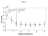
- FIG. 5 shows the application of the control strategy with a CCD camera, showing the image index as number of pixels, and the damper opening.
- FIG. 6 depicts the general control scheme of a boiler's burner.
- the invention consists of a system for flame detection and analysis typically of gas and fuel oil, using optical devices, typically photo detectors or cameras, located in the rear part of a furnace or in locations where they can target the flame reaction zone.
- optical signals are transmitted to processing and control module, typically a computer system, that uses specific algorithms to process the optical signals, generating indicators to diagnose the combustion quality and to optimize equipment operation in terms of its efficiency and polluting emissions.
- This flame detection and analysis system can be used as an autonomous system to diagnose industrial equipment or as part of a combustion control system in existing burners, boilers or industrial furnaces.
- air control can be decoupled from the fuel control system, which is novel compared to traditional control schemes. For this reason, the system includes a control strategy that interacts with typical control equipment, optimizing the use of combustion air.
- the invention has the following main components:
- the system constantly seeks to maintain the equipment operating at maximum, and preferably ideal, performance with the lowest levels of pollutant emissions.
- the photo detectors use the spectral information from the flames to generate a control index for optimizing the combustion process.
- a control strategy based on the ratio between the C2/CH can be established. This parameter is a good indicator of combustion quality since it can detect the conditions under which the burner operates with low pollutant emission levels (CO and soot) yet at high performance.
- the spectral information will correspond to soot emissions in wave lengths between 400 and 750 nm.
- the sensors CCD camera or photodiode
- the processing unit generates a combustion state index that is used to identify the best operational conditions and then acts on the actuator, which in turn acts on the servomotor to regulate the combustion air.
- the silicon photodiodes of the present invention use filters that restrict the intensities received from the flame to narrow bands relative to radical C2 and CH emission. This strategy implies the use of at least 2 photodiodes.
- the invention contemplates software for real-time analysis of flames using CCD cameras.
- a set of images are averaged and then processed according to a predefined method (“clustering”, “inter-class”, “metric”, “entropy”, “moments” or manually).
- This process is performed in different color spaces (RGB, HSV, HSL, HSI), where a number of pixels of 2D Histograms, corresponding to regions of the flame correlated with the formation of pollutant species (CO, soot and NOx), is calculated. This estimated value is used as an index to control the combustion process.
- the present invention encompasses a detection and analysis system for gas and oil flames based on optical devices (photo detectors or cameras) and algorithms to diagnose combustion quality and to optimize operation in terms of performance and pollutant emissions.
- the developed system achieves reductions in fuel consumption and emissions. Additionally, it has the following advantages compared with conventional systems:
- the proposed system provides faster monitoring and control responses.
- the system monitors the combustion process at its origin, i.e. “the flame's reaction zone”, differing from systems based on gas analysis, whose monitors are normally located in the chimney.
- Optical sensors are not intrusive. Indeed, measuring flame characteristics by optical methods does not alter boiler or furnace functioning in any way. Thus, system maintenance costs are lower than control systems using a gas analyzer that must be regularly recalibrated due to depositions of soot particles in the measurement probe.
- the maintenance cost is low since the devices are easily available in the market. Additionally, their useful life can be from several months to years, depending on the operating conditions, and they can be easily replaced in case of failure.
- the proposed system can be configured as either a flame monitoring system or a as a backup control system in the case of main control system failure.
- the system provides the followings economic benefits: fuel savings, operational costs savings, and lower risk of sanctions due to polluting emissions.
- the system can also provide additional safety and support to an already existing control system.
- the technology has been implemented in a boiler of 150 kW.
- the search strategy for the slope value is based on a simple comparison algorithm, which determines the slope between the ratio C2/CH and the damper opening in order to compare it to the desired slope. Since in this case, the slope is zero at the point of maximum operation, the control strategy changes burner power.
- FIGS. 1 and 2 The results obtained using this method are depicted in FIGS. 1 and 2 . This method takes nearly 10 minutes to find the optimal point of burner operation. The boiler efficiency obtained is 86% and the CO emission is under the 100 ppm.
- the line with rhombuses corresponds to damper opening and the line with triangles corresponds to boiler efficiency.
- the line with rhombuses corresponds to the ratio C2/CH and the line with squares corresponds to CO emissions.
- the gradient method is based on the equilibrium condition, where the method determines to open or close the damper in order to obtain the position where ratio C2/CH is maximized. This method needs to know the gradient between the ratio C2/CH and the damper opening.
- FIGS. 3 and 4 show the results obtained using this method, where the boiler efficiency is over 84% and the CO emissions under the 100 ppm.
- the quadratic algorithm method fits the curves obtained from the ratio C2/CH for different burner power levels to a Taylor series (Equation 1), discarding the terms larger than the third order. Thus, it is possible to obtain the damper opening that maximizes the ratio C2/CH.
- FIG. 5 shows the application of the control strategy, using a CCD camera installed in the boiler for an operation with natural gas.
- the image index obtained by post-processing software, is able to follow the changes in the regulation variable that corresponds to the opening of the air input valve. Indeed, it can be especially observed that the increased signal corresponds to a condition when the combustion deteriorates.
- the system marks the guideline to control the equipment to reach an ideal point in order to obtain maximum boiler efficiency with CO emissions at acceptable levels according to international standards.
- FIG. 6 depicts the general control scheme implemented in a boiler's burner. We can see: the combustion chamber where the flame lodges ( 1 ), the sensor ( 2 ) that records the selected signals emitted by the flame, the processing and control module ( 3 ) and the actuator ( 4 ) that acts on the burner damper.
Abstract
Description
-
- a) A sensor (photo detectors or cameras) that it is targeted by an optical path towards the flame reaction zone;
- b) A processing and control module;
- c) An actuator, to manipulate the air flow.
-
- 1. Slope based
- 2. Gradient Method.
- 3. Quadratic algorithm for extreme searching.
Claims (15)
Applications Claiming Priority (2)
| Application Number | Priority Date | Filing Date | Title |
|---|---|---|---|
| CL1742/2007 | 2007-06-14 | ||
| CL2007001742 | 2007-06-14 |
Publications (2)
| Publication Number | Publication Date |
|---|---|
| US20090017406A1 US20090017406A1 (en) | 2009-01-15 |
| US8070482B2 true US8070482B2 (en) | 2011-12-06 |
Family
ID=40253442
Family Applications (1)
| Application Number | Title | Priority Date | Filing Date |
|---|---|---|---|
| US12/139,657 Expired - Fee Related US8070482B2 (en) | 2007-06-14 | 2008-06-16 | Combustion control system of detection and analysis of gas or fuel oil flames using optical devices |
Country Status (1)
| Country | Link |
|---|---|
| US (1) | US8070482B2 (en) |
Cited By (9)
| Publication number | Priority date | Publication date | Assignee | Title |
|---|---|---|---|---|
| US20100292906A1 (en) * | 2009-05-18 | 2010-11-18 | Raymond Girouard | Method of controlling engine performance |
| US8757872B2 (en) * | 2009-12-16 | 2014-06-24 | Abb Research Ltd | Optical flame sensor |
| US9335216B2 (en) | 2013-06-24 | 2016-05-10 | General Electric Company | System and method for on-line optical monitoring and control of a gas turbine engine |
| US20160158895A1 (en) * | 2011-09-23 | 2016-06-09 | Lucas-Milhaupt, Inc. | Luminescent Braze Preforms |
| US9702555B2 (en) | 2014-10-07 | 2017-07-11 | Honeywell International Inc. | Equipment and method for furnace visualization using virtual interactive windows |
| US9851111B1 (en) * | 2009-10-30 | 2017-12-26 | C. Cowles & Company | Thermal reduction through activity based thermal targeting to enhance heating system efficiency |
| US10429068B2 (en) | 2013-01-11 | 2019-10-01 | Ademco Inc. | Method and system for starting an intermittent flame-powered pilot combustion system |
| US11236930B2 (en) | 2018-05-01 | 2022-02-01 | Ademco Inc. | Method and system for controlling an intermittent pilot water heater system |
| US11656000B2 (en) | 2019-08-14 | 2023-05-23 | Ademco Inc. | Burner control system |
Families Citing this family (18)
| Publication number | Priority date | Publication date | Assignee | Title |
|---|---|---|---|---|
| US20110008737A1 (en) * | 2009-06-15 | 2011-01-13 | General Electric Company | Optical sensors for combustion control |
| US8456634B2 (en) * | 2009-06-15 | 2013-06-04 | General Electric Company | Optical interrogation sensors for combustion control |
| US8219247B2 (en) * | 2009-11-19 | 2012-07-10 | Air Products And Chemicals, Inc. | Method of operating a furnace |
| US8177544B2 (en) | 2010-04-09 | 2012-05-15 | Honeywell International Inc. | Selective lockout in a fuel-fired appliance |
| US9388984B2 (en) | 2010-04-09 | 2016-07-12 | Honeywell International Inc. | Flame detection in a fuel fired appliance |
| US8523560B2 (en) | 2010-04-09 | 2013-09-03 | Honeywell International Inc. | Spark detection in a fuel fired appliance |
| AT510702B1 (en) * | 2010-12-01 | 2012-06-15 | Avl List Gmbh | METHOD AND DEVICE FOR EVALUATING THE CONDITION OF A FUEL AIR MIXTURE |
| TWI421721B (en) * | 2010-12-09 | 2014-01-01 | Ind Tech Res Inst | A method for combustion flames diagnosis |
| US20120208136A1 (en) * | 2011-02-11 | 2012-08-16 | General Electric Company | System and method for operating a combustor |
| US20120208137A1 (en) * | 2011-02-11 | 2012-08-16 | General Electric Company | System and method for operating a combustor |
| CN102367957B (en) * | 2011-09-28 | 2013-10-02 | 南京创能电力科技开发有限公司 | Integrated intelligent flame detection device |
| CA2789642C (en) * | 2012-09-14 | 2020-06-09 | Nova Chemicals Corporation | Improved industrial furnace |
| US10208954B2 (en) | 2013-01-11 | 2019-02-19 | Ademco Inc. | Method and system for controlling an ignition sequence for an intermittent flame-powered pilot combustion system |
| US10746470B2 (en) * | 2017-06-29 | 2020-08-18 | Air Products & Chemicals, Inc. | Method of operating a furnace |
| TR201711637A2 (en) * | 2017-08-08 | 2017-09-21 | Suphi Ural | COAL DUST EXPLOSIBILITY MEASUREMENT DEVICE AND METHOD WITH CAMERA IMAGE BASED |
| CN111951508B (en) * | 2020-07-03 | 2023-01-17 | 北京中安安博文化科技有限公司 | Fire classification method, device, medium and electronic equipment |
| CN114562368A (en) * | 2022-02-15 | 2022-05-31 | 华瑞(江苏)燃机服务有限公司 | Combustion pulsation signal processing system and method of automatic combustion adjusting system of gas turbine |
| CN117663397B (en) * | 2024-01-30 | 2024-04-09 | 深圳市永宏光热能科技有限公司 | Air mixing control method and system for air conditioner hot air burner |
Citations (77)
| Publication number | Priority date | Publication date | Assignee | Title |
|---|---|---|---|---|
| GB1032697A (en) | ||||
| US2404903A (en) * | 1943-08-23 | 1946-07-30 | Wheelco Instr Company | Automatic burner control apparatus |
| US2592847A (en) * | 1948-01-20 | 1952-04-15 | Babicz George | Protecting system for photoelectric cells in liquid fuel burner controls |
| US2804131A (en) * | 1953-06-05 | 1957-08-27 | Gen Controls Co | Flame responsive safety control system using prism and light chopper |
| US3080708A (en) * | 1960-09-14 | 1963-03-12 | Phillips Petroleum Co | Fuel-air ratio control for a reaction engine |
| US3292855A (en) * | 1965-10-01 | 1966-12-20 | Exxon Research Engineering Co | Microwave sensing apparatus and method for burner control |
| US3368753A (en) * | 1965-08-16 | 1968-02-13 | Bailey Meter Co | Measurement and control of burner excess air |
| US3369749A (en) * | 1967-02-17 | 1968-02-20 | Exxon Research Engineering Co | Low excess air operation of multipleburner residual-fuel-fired furnaces |
| US3374950A (en) * | 1965-04-12 | 1968-03-26 | Exxon Research Engineering Co | Photo-pyrometric control system for efficient combustion in multiple-burner, residual-fuel-fired furnaces |
| US3814570A (en) * | 1972-05-31 | 1974-06-04 | M Pillard | Apparatus for automatic correction of the positioning control of a burner |
| US3861855A (en) * | 1973-12-19 | 1975-01-21 | B S C Ind Corp | Automatic combustion control |
| GB1396384A (en) | 1972-05-22 | 1975-06-04 | Central Electr Generat Board | Flame monitoring apparatus and method |
| US3902841A (en) * | 1973-12-14 | 1975-09-02 | Forney International | Infrared dynamic flame detector |
| US4039844A (en) * | 1975-03-20 | 1977-08-02 | Electronics Corporation Of America | Flame monitoring system |
| US4043742A (en) | 1976-05-17 | 1977-08-23 | Environmental Data Corporation | Automatic burner monitor and control for furnaces |
| US4362499A (en) | 1980-12-29 | 1982-12-07 | Fisher Controls Company, Inc. | Combustion control system and method |
| JPS5835323A (en) * | 1981-08-26 | 1983-03-02 | Ebara Corp | Air ratio measuring device for burner |
| US4435149A (en) | 1981-12-07 | 1984-03-06 | Barnes Engineering Company | Method and apparatus for monitoring the burning efficiency of a furnace |
| US4455656A (en) | 1979-03-07 | 1984-06-19 | Hitachi, Ltd. | Combustion control circuit |
| US4461615A (en) | 1981-07-24 | 1984-07-24 | Tokyo Shibaura Denki Kabushiki Kaisha | Combustion control device |
| JPS6036825A (en) | 1983-08-10 | 1985-02-26 | Hitachi Ltd | Control method for combustion flame and device thereof |
| JPS6036824A (en) * | 1983-08-05 | 1985-02-26 | Babcock Hitachi Kk | Optical flame detector |
| US4509912A (en) | 1975-12-16 | 1985-04-09 | Vanberkum Robert A | Combustion efficiency improving apparatus |
| JPS60162121A (en) * | 1984-02-01 | 1985-08-23 | Hitachi Ltd | Flame monitoring device |
| JPS60169015A (en) * | 1984-02-10 | 1985-09-02 | Hitachi Ltd | Burning condition diagnosing method |
| JPS60213727A (en) * | 1984-04-10 | 1985-10-26 | Yamatake Honeywell Co Ltd | Air-fuel ratio detecting device |
| JPS60213725A (en) * | 1984-04-10 | 1985-10-26 | Yamatake Honeywell Co Ltd | Air-fuel ratio detecting device |
| US4553924A (en) | 1982-08-12 | 1985-11-19 | Westinghouse Electric Corp. | Jackshaft controlled boiler combustion control system |
| US4653998A (en) * | 1984-01-27 | 1987-03-31 | Hitachi, Ltd. | Furnace system |
| JPS62134418A (en) * | 1985-12-06 | 1987-06-17 | Babcock Hitachi Kk | Burner control device |
| JPS62261819A (en) * | 1986-05-08 | 1987-11-14 | Ngk Spark Plug Co Ltd | Air-fuel ratio detector |
| JPS63315829A (en) * | 1987-06-19 | 1988-12-23 | Hitachi Ltd | Burner combustion monitoring control method |
| US4820046A (en) * | 1986-12-01 | 1989-04-11 | Hitachi, Ltd. | Spectroscope apparatus and reaction apparatus using the same |
| JPH01312319A (en) * | 1988-06-10 | 1989-12-18 | Hitachi Ltd | Boiler combustion state monitoring device |
| US4913647A (en) * | 1986-03-19 | 1990-04-03 | Honeywell Inc. | Air fuel ratio control |
| US5112215A (en) * | 1991-06-20 | 1992-05-12 | Physical Sciences, Inc. | Apparatus for combustion, pollution and chemical process control |
| DE4042025A1 (en) * | 1990-12-28 | 1992-07-02 | Hitachi Ltd | Flame burn condition evaluator for IC engine - uses optic monitoring of flame with separate wavelength metering |
| US5139412A (en) * | 1990-05-08 | 1992-08-18 | Weyerhaeuser Company | Method and apparatus for profiling the bed of a furnace |
| US5186146A (en) * | 1990-12-20 | 1993-02-16 | Hitachi, Ltd. | Combustion evaluation apparatus and combustion controller |
| US5222887A (en) * | 1992-01-17 | 1993-06-29 | Gas Research Institute | Method and apparatus for fuel/air control of surface combustion burners |
| US5249954A (en) * | 1992-07-07 | 1993-10-05 | Electric Power Research Institute, Inc. | Integrated imaging sensor/neural network controller for combustion systems |
| US5252060A (en) * | 1992-03-27 | 1993-10-12 | Mckinnon J Thomas | Infrared laser fault detection method for hazardous waste incineration |
| US5257496A (en) * | 1992-05-05 | 1993-11-02 | General Electric Company | Combustion control for producing low NOx emissions through use of flame spectroscopy |
| US5263851A (en) * | 1991-05-10 | 1993-11-23 | Toyota Jidosha Kabushiki Kaisha | Combustion control system for burner |
| US5368471A (en) * | 1991-11-20 | 1994-11-29 | The Babcock & Wilcox Company | Method and apparatus for use in monitoring and controlling a black liquor recovery furnace |
| US5480298A (en) * | 1992-05-05 | 1996-01-02 | General Electric Company | Combustion control for producing low NOx emissions through use of flame spectroscopy |
| US5487266A (en) * | 1992-05-05 | 1996-01-30 | General Electric Company | Combustion control for producing low NOx emissions through use of flame spectroscopy |
| US5544478A (en) * | 1994-11-15 | 1996-08-13 | General Electric Company | Optical sensing of combustion dynamics |
| US5547369A (en) * | 1993-03-17 | 1996-08-20 | Hitachi, Ltd. | Camera, spectrum analysis system, and combustion evaluation apparatus employing them |
| US5578828A (en) * | 1994-11-15 | 1996-11-26 | General Electric Company | Flame sensor window coating compensation |
| CA2165350A1 (en) | 1995-08-03 | 1997-02-04 | Gianpiero Turrin | A device for automatically controlling the operation of a burner in general |
| US5659133A (en) * | 1996-04-22 | 1997-08-19 | Astropower, Inc. | High-temperature optical combustion chamber sensor |
| US5691700A (en) * | 1994-09-15 | 1997-11-25 | United Technologies Corporation | Apparatus and method using non-contact light sensing with selective field of view, low input impedance, current-mode amplification and/or adjustable switching level |
| JPH109562A (en) * | 1996-06-26 | 1998-01-16 | Nippon Furnace Kogyo Kaisha Ltd | Method for diagnosing combustion state |
| US5785512A (en) * | 1996-12-17 | 1998-07-28 | Fireye, Inc. | Infrared emittance combustion analyzer |
| US5794549A (en) | 1996-01-25 | 1998-08-18 | Applied Synergistics, Inc. | Combustion optimization system |
| US5971747A (en) * | 1996-06-21 | 1999-10-26 | Lemelson; Jerome H. | Automatically optimized combustion control |
| US6060719A (en) * | 1997-06-24 | 2000-05-09 | Gas Research Institute | Fail safe gas furnace optical flame sensor using a transconductance amplifier and low photodiode current |
| US6071114A (en) * | 1996-06-19 | 2000-06-06 | Meggitt Avionics, Inc. | Method and apparatus for characterizing a combustion flame |
| US6113384A (en) * | 1996-03-25 | 2000-09-05 | Sebastiani; Enrico | Regulation of gas combustion through flame position |
| US6227842B1 (en) * | 1998-12-30 | 2001-05-08 | Jerome H. Lemelson | Automatically optimized combustion control |
| US6247918B1 (en) * | 1998-12-16 | 2001-06-19 | Forney Corporation | Flame monitoring methods and apparatus |
| US6455851B1 (en) * | 2000-03-28 | 2002-09-24 | Air Instruments And Measurement, Inc. | Spectroscopic remote sensing exhaust emission monitoring system |
| US6468069B2 (en) * | 1999-10-25 | 2002-10-22 | Jerome H. Lemelson | Automatically optimized combustion control |
| US6551094B2 (en) * | 1998-09-11 | 2003-04-22 | Siemens Aktiengesellschaft | Method and device for determining a soot charge in a combustion chamber |
| US20040033457A1 (en) * | 2002-08-19 | 2004-02-19 | Abb Inc. | Combustion emission estimation with flame sensing system |
| US20040156420A1 (en) * | 1996-12-19 | 2004-08-12 | Huston John T. | Pyrometer for measuring the temperature of a gas component within a furnance |
| US6780378B2 (en) * | 2001-06-28 | 2004-08-24 | Gas Technology Institute | Method for measuring concentrations of gases and vapors using controlled flames |
| US6823662B1 (en) * | 1999-10-21 | 2004-11-30 | Nissan Motor Co., Ltd. | Exhaust gas purifying system |
| US7217121B2 (en) * | 2000-06-26 | 2007-05-15 | Thomson Murray J | Method and apparatus for improved process control in combustion applications |
| US7280891B2 (en) * | 2003-12-11 | 2007-10-09 | Abb Inc. | Signal processing technique for improved flame scanner discrimination |
| US7289032B2 (en) * | 2005-02-24 | 2007-10-30 | Alstom Technology Ltd | Intelligent flame scanner |
| US20080050684A1 (en) * | 2006-08-25 | 2008-02-28 | Flynn Thomas J | Method for controlling air distribution in a cyclone furnace |
| US7353140B2 (en) * | 2001-11-14 | 2008-04-01 | Electric Power Research Institute, Inc. | Methods for monitoring and controlling boiler flames |
| US7520744B2 (en) * | 2004-07-27 | 2009-04-21 | Powtec Intelligent Technologies Gmbh | Monitoring device with scraper unit |
| US7574039B2 (en) * | 2005-03-24 | 2009-08-11 | Honeywell International Inc. | Video based fire detection system |
| US7710280B2 (en) * | 2006-05-12 | 2010-05-04 | Fossil Power Systems Inc. | Flame detection device and method of detecting flame |
-
2008
- 2008-06-16 US US12/139,657 patent/US8070482B2/en not_active Expired - Fee Related
Patent Citations (81)
| Publication number | Priority date | Publication date | Assignee | Title |
|---|---|---|---|---|
| GB1032697A (en) | ||||
| US2404903A (en) * | 1943-08-23 | 1946-07-30 | Wheelco Instr Company | Automatic burner control apparatus |
| US2592847A (en) * | 1948-01-20 | 1952-04-15 | Babicz George | Protecting system for photoelectric cells in liquid fuel burner controls |
| US2804131A (en) * | 1953-06-05 | 1957-08-27 | Gen Controls Co | Flame responsive safety control system using prism and light chopper |
| US3080708A (en) * | 1960-09-14 | 1963-03-12 | Phillips Petroleum Co | Fuel-air ratio control for a reaction engine |
| US3374950A (en) * | 1965-04-12 | 1968-03-26 | Exxon Research Engineering Co | Photo-pyrometric control system for efficient combustion in multiple-burner, residual-fuel-fired furnaces |
| US3368753A (en) * | 1965-08-16 | 1968-02-13 | Bailey Meter Co | Measurement and control of burner excess air |
| US3292855A (en) * | 1965-10-01 | 1966-12-20 | Exxon Research Engineering Co | Microwave sensing apparatus and method for burner control |
| US3369749A (en) * | 1967-02-17 | 1968-02-20 | Exxon Research Engineering Co | Low excess air operation of multipleburner residual-fuel-fired furnaces |
| GB1396384A (en) | 1972-05-22 | 1975-06-04 | Central Electr Generat Board | Flame monitoring apparatus and method |
| US3814570A (en) * | 1972-05-31 | 1974-06-04 | M Pillard | Apparatus for automatic correction of the positioning control of a burner |
| US3902841A (en) * | 1973-12-14 | 1975-09-02 | Forney International | Infrared dynamic flame detector |
| US3861855A (en) * | 1973-12-19 | 1975-01-21 | B S C Ind Corp | Automatic combustion control |
| US4039844A (en) * | 1975-03-20 | 1977-08-02 | Electronics Corporation Of America | Flame monitoring system |
| US4509912A (en) | 1975-12-16 | 1985-04-09 | Vanberkum Robert A | Combustion efficiency improving apparatus |
| US4043742A (en) | 1976-05-17 | 1977-08-23 | Environmental Data Corporation | Automatic burner monitor and control for furnaces |
| US4455656A (en) | 1979-03-07 | 1984-06-19 | Hitachi, Ltd. | Combustion control circuit |
| US4362499A (en) | 1980-12-29 | 1982-12-07 | Fisher Controls Company, Inc. | Combustion control system and method |
| US4461615A (en) | 1981-07-24 | 1984-07-24 | Tokyo Shibaura Denki Kabushiki Kaisha | Combustion control device |
| JPS5835323A (en) * | 1981-08-26 | 1983-03-02 | Ebara Corp | Air ratio measuring device for burner |
| US4435149A (en) | 1981-12-07 | 1984-03-06 | Barnes Engineering Company | Method and apparatus for monitoring the burning efficiency of a furnace |
| US4553924A (en) | 1982-08-12 | 1985-11-19 | Westinghouse Electric Corp. | Jackshaft controlled boiler combustion control system |
| JPS6036824A (en) * | 1983-08-05 | 1985-02-26 | Babcock Hitachi Kk | Optical flame detector |
| JPS6036825A (en) | 1983-08-10 | 1985-02-26 | Hitachi Ltd | Control method for combustion flame and device thereof |
| US4653998A (en) * | 1984-01-27 | 1987-03-31 | Hitachi, Ltd. | Furnace system |
| JPS60162121A (en) * | 1984-02-01 | 1985-08-23 | Hitachi Ltd | Flame monitoring device |
| JPS60169015A (en) * | 1984-02-10 | 1985-09-02 | Hitachi Ltd | Burning condition diagnosing method |
| JPS60213727A (en) * | 1984-04-10 | 1985-10-26 | Yamatake Honeywell Co Ltd | Air-fuel ratio detecting device |
| JPS60213725A (en) * | 1984-04-10 | 1985-10-26 | Yamatake Honeywell Co Ltd | Air-fuel ratio detecting device |
| JPS62134418A (en) * | 1985-12-06 | 1987-06-17 | Babcock Hitachi Kk | Burner control device |
| US4913647A (en) * | 1986-03-19 | 1990-04-03 | Honeywell Inc. | Air fuel ratio control |
| JPS62261819A (en) * | 1986-05-08 | 1987-11-14 | Ngk Spark Plug Co Ltd | Air-fuel ratio detector |
| US4820046A (en) * | 1986-12-01 | 1989-04-11 | Hitachi, Ltd. | Spectroscope apparatus and reaction apparatus using the same |
| JPS63315829A (en) * | 1987-06-19 | 1988-12-23 | Hitachi Ltd | Burner combustion monitoring control method |
| JPH01312319A (en) * | 1988-06-10 | 1989-12-18 | Hitachi Ltd | Boiler combustion state monitoring device |
| US5139412A (en) * | 1990-05-08 | 1992-08-18 | Weyerhaeuser Company | Method and apparatus for profiling the bed of a furnace |
| US5186146A (en) * | 1990-12-20 | 1993-02-16 | Hitachi, Ltd. | Combustion evaluation apparatus and combustion controller |
| DE4042025A1 (en) * | 1990-12-28 | 1992-07-02 | Hitachi Ltd | Flame burn condition evaluator for IC engine - uses optic monitoring of flame with separate wavelength metering |
| US5263851A (en) * | 1991-05-10 | 1993-11-23 | Toyota Jidosha Kabushiki Kaisha | Combustion control system for burner |
| US5112215A (en) * | 1991-06-20 | 1992-05-12 | Physical Sciences, Inc. | Apparatus for combustion, pollution and chemical process control |
| US5275553A (en) * | 1991-06-20 | 1994-01-04 | Psi Environmental Instruments Corp. | Apparatus for combustion, pollution and chemical process control |
| US5368471A (en) * | 1991-11-20 | 1994-11-29 | The Babcock & Wilcox Company | Method and apparatus for use in monitoring and controlling a black liquor recovery furnace |
| US5222887A (en) * | 1992-01-17 | 1993-06-29 | Gas Research Institute | Method and apparatus for fuel/air control of surface combustion burners |
| US5252060A (en) * | 1992-03-27 | 1993-10-12 | Mckinnon J Thomas | Infrared laser fault detection method for hazardous waste incineration |
| US5257496A (en) * | 1992-05-05 | 1993-11-02 | General Electric Company | Combustion control for producing low NOx emissions through use of flame spectroscopy |
| US5303684A (en) * | 1992-05-05 | 1994-04-19 | General Electric Company | Combustion control for producing low NOx emissions through use of flame spectroscopy |
| US5480298A (en) * | 1992-05-05 | 1996-01-02 | General Electric Company | Combustion control for producing low NOx emissions through use of flame spectroscopy |
| US5487266A (en) * | 1992-05-05 | 1996-01-30 | General Electric Company | Combustion control for producing low NOx emissions through use of flame spectroscopy |
| US5249954A (en) * | 1992-07-07 | 1993-10-05 | Electric Power Research Institute, Inc. | Integrated imaging sensor/neural network controller for combustion systems |
| US5547369A (en) * | 1993-03-17 | 1996-08-20 | Hitachi, Ltd. | Camera, spectrum analysis system, and combustion evaluation apparatus employing them |
| US5691700A (en) * | 1994-09-15 | 1997-11-25 | United Technologies Corporation | Apparatus and method using non-contact light sensing with selective field of view, low input impedance, current-mode amplification and/or adjustable switching level |
| US5578828A (en) * | 1994-11-15 | 1996-11-26 | General Electric Company | Flame sensor window coating compensation |
| US5544478A (en) * | 1994-11-15 | 1996-08-13 | General Electric Company | Optical sensing of combustion dynamics |
| CA2165350A1 (en) | 1995-08-03 | 1997-02-04 | Gianpiero Turrin | A device for automatically controlling the operation of a burner in general |
| US5607294A (en) | 1995-08-03 | 1997-03-04 | Sit La Precisa S.R.L. | Device for automatically controlling the operation of a burner in general |
| US5794549A (en) | 1996-01-25 | 1998-08-18 | Applied Synergistics, Inc. | Combustion optimization system |
| US6113384A (en) * | 1996-03-25 | 2000-09-05 | Sebastiani; Enrico | Regulation of gas combustion through flame position |
| US5659133A (en) * | 1996-04-22 | 1997-08-19 | Astropower, Inc. | High-temperature optical combustion chamber sensor |
| US6071114A (en) * | 1996-06-19 | 2000-06-06 | Meggitt Avionics, Inc. | Method and apparatus for characterizing a combustion flame |
| US5971747A (en) * | 1996-06-21 | 1999-10-26 | Lemelson; Jerome H. | Automatically optimized combustion control |
| US5993194A (en) * | 1996-06-21 | 1999-11-30 | Lemelson; Jerome H. | Automatically optimized combustion control |
| JPH109562A (en) * | 1996-06-26 | 1998-01-16 | Nippon Furnace Kogyo Kaisha Ltd | Method for diagnosing combustion state |
| US5785512A (en) * | 1996-12-17 | 1998-07-28 | Fireye, Inc. | Infrared emittance combustion analyzer |
| US20040156420A1 (en) * | 1996-12-19 | 2004-08-12 | Huston John T. | Pyrometer for measuring the temperature of a gas component within a furnance |
| US6060719A (en) * | 1997-06-24 | 2000-05-09 | Gas Research Institute | Fail safe gas furnace optical flame sensor using a transconductance amplifier and low photodiode current |
| US6551094B2 (en) * | 1998-09-11 | 2003-04-22 | Siemens Aktiengesellschaft | Method and device for determining a soot charge in a combustion chamber |
| US6247918B1 (en) * | 1998-12-16 | 2001-06-19 | Forney Corporation | Flame monitoring methods and apparatus |
| US6227842B1 (en) * | 1998-12-30 | 2001-05-08 | Jerome H. Lemelson | Automatically optimized combustion control |
| US6823662B1 (en) * | 1999-10-21 | 2004-11-30 | Nissan Motor Co., Ltd. | Exhaust gas purifying system |
| US6468069B2 (en) * | 1999-10-25 | 2002-10-22 | Jerome H. Lemelson | Automatically optimized combustion control |
| US6455851B1 (en) * | 2000-03-28 | 2002-09-24 | Air Instruments And Measurement, Inc. | Spectroscopic remote sensing exhaust emission monitoring system |
| US7217121B2 (en) * | 2000-06-26 | 2007-05-15 | Thomson Murray J | Method and apparatus for improved process control in combustion applications |
| US6780378B2 (en) * | 2001-06-28 | 2004-08-24 | Gas Technology Institute | Method for measuring concentrations of gases and vapors using controlled flames |
| US7353140B2 (en) * | 2001-11-14 | 2008-04-01 | Electric Power Research Institute, Inc. | Methods for monitoring and controlling boiler flames |
| US20040033457A1 (en) * | 2002-08-19 | 2004-02-19 | Abb Inc. | Combustion emission estimation with flame sensing system |
| US7280891B2 (en) * | 2003-12-11 | 2007-10-09 | Abb Inc. | Signal processing technique for improved flame scanner discrimination |
| US7520744B2 (en) * | 2004-07-27 | 2009-04-21 | Powtec Intelligent Technologies Gmbh | Monitoring device with scraper unit |
| US7289032B2 (en) * | 2005-02-24 | 2007-10-30 | Alstom Technology Ltd | Intelligent flame scanner |
| US7574039B2 (en) * | 2005-03-24 | 2009-08-11 | Honeywell International Inc. | Video based fire detection system |
| US7710280B2 (en) * | 2006-05-12 | 2010-05-04 | Fossil Power Systems Inc. | Flame detection device and method of detecting flame |
| US20080050684A1 (en) * | 2006-08-25 | 2008-02-28 | Flynn Thomas J | Method for controlling air distribution in a cyclone furnace |
Non-Patent Citations (20)
| Title |
|---|
| Angulo, J. et al., Segmentación de imágenes en color utilizando histogramas bi-variables en espacios color polares luminancia/saturación/matiz, Revista "Computación y Sistemas", vol. 8, No. 4, Jun. 2005, pp. 1-19. (article including English Abstract-19 pages total), Spanish w/English Abstract. |
| Angulo, J. et al., Segmentación de imágenes en color utilizando histogramas bi-variables en espacios color polares luminancia/saturación/matiz, Revista "Computación y Sistemas", vol. 8, No. 4, Jun. 2005, pp. 1-19. (article including English Abstract—19 pages total), Spanish w/English Abstract. |
| Arias, L. et al., A Measuring Method Based on Photodiodes for the Diagnostic of Optimal Combustion Conditions, printed from Advanced Computational Methods in Heat Transfer X, WIT Transactions on Engineering Sciences, vol. 61, 2008, pp. 201-209. (9 pages). |
| Boysen, C., Análisis y Control de Llama Mediante Métodos Ópticos, memoria para obtener el titulo de Ingeniero Civil Electrónico, Departamento de Ingenieria Eléctrica, Universidad de Concepción, Chile, 2004, pp. 1-74. (article + 1 page English Abstract-75 pages total), Spanish w/English Abstract. |
| Boysen, C., Análisis y Control de Llama Mediante Métodos Ópticos, memoria para obtener el titulo de Ingeniero Civil Electrónico, Departamento de Ingenieria Eléctrica, Universidad de Concepción, Chile, 2004, pp. 1-74. (article + 1 page English Abstract—75 pages total), Spanish w/English Abstract. |
| Farias, O. et al., Diagnóstico de la Combustión de Gas y Petróleo Mediante Análisis del Espectro Visible de la Llama, 8° Congreso Iberoamericano de Ingenieria Mecánica, Cusco (Perú), Oct. 23-25, 2007. (article + 1 page English Abstract-10 pages total), Spanish w/English Abstract. |
| Farias, O. et al., Diagnóstico de la Combustión de Gas y Petróleo Mediante Análisis del Espectro Visible de la Llama, 8° Congreso Iberoamericano de Ingenieria Mecánica, Cusco (Perú), Oct. 23-25, 2007. (article + 1 page English Abstract—10 pages total), Spanish w/English Abstract. |
| Farias, O., Diagnostico de al Combustión a Partir del Espectro de Llamas Luminosas, printed from PACAM VI, Six Pan American Congress of Applied Mechanics), Rio de Janeiro, Brazil, Jan. 1999. (article + 1 page English Abstract-5 pages total), Spanish w/English Abstract. |
| Farias, O., Diagnostico de al Combustión a Partir del Espectro de Llamas Luminosas, printed from PACAM VI, Six Pan American Congress of Applied Mechanics), Rio de Janeiro, Brazil, Jan. 1999. (article + 1 page English Abstract—5 pages total), Spanish w/English Abstract. |
| Farias, O., summary and table of contents of "Towards the development of an Optimal Combustion Control in Fuel-Oil Boilers from the Flame Emission Spectrum", Thesis for the Degree of Doctor of Applied Sciences, Laboratory of Thermodynamics, University of Liège, Belgium, Sep. 1997. 3 page Abstract/Summary plus 6 page TOC/Index. (9 pages total). |
| Flame Doctor® Burner Diagnostic System for Individual Burner Optimization, The Babcock & Wilcox Company, Barberton, Ohio, 2004. (2 pages). |
| Khesin, M., Diagnosing and Optimizing Combustion by Frequency Spectra Analysis, Physical Sciences, Inc., Conceptual SpectraTune(TM) System. (2 pages). |
| Khesin, M., Diagnosing and Optimizing Combustion by Frequency Spectra Analysis, Physical Sciences, Inc., Conceptual SpectraTune™ System. (2 pages). |
| MK Combustion Optimization System, GE Power Systems, Twinsburg, Ohio, GEA-13485. (2 pages). |
| Sbarbaro, D. et al., Real-time monitoring and characterization of flames by principal-component analysis, Combustion and Flame, vol. 132, 2003, pp. 591-595. (5 pages). |
| Tartari, P. et al., Photodiode for Controlling Combustion (VI), Technical Report for WMTE, University of Liège, Belgium, Mar. 2003. (21 pages). |
| Vora, P. et al., Linear Models for Digital Cameras, Hewlett-Packard Laboratories, Dept. of Psychology, University of California, Santa Barbara, 2000,pp. 1-6. (6 pages). |
| Ward Perez-Canto, Monitoreo de Llama en Homo HDT Utilizando Análisis de Imágenes, (memoria para obtener el titulo de Ingeniero Civil Electrónico, Departamento de Ingenieria Eléctrica), Universidad de Concepción, Chile, Jul. 2006. (article + 1 page English abstract-88 pages total) Spanish w/English Abstract, Spanish w/English Abstract. |
| Ward Perez-Canto, Monitoreo de Llama en Homo HDT Utilizando Análisis de Imágenes, (memoria para obtener el titulo de Ingeniero Civil Electrónico, Departamento de Ingenieria Eléctrica), Universidad de Concepción, Chile, Jul. 2006. (article + 1 page English abstract—88 pages total) Spanish w/English Abstract, Spanish w/English Abstract. |
| Zuo B. et al., Pollutant Generation by Combustion of Oil Boilers, Bull. Soc. Chim. Belg., vol. 101, No. 10, 1992. (6 pages). |
Cited By (13)
| Publication number | Priority date | Publication date | Assignee | Title |
|---|---|---|---|---|
| US8265851B2 (en) * | 2009-05-18 | 2012-09-11 | Closed-Loop Engine Technology, Llc | Method of controlling engine performance |
| US20100292906A1 (en) * | 2009-05-18 | 2010-11-18 | Raymond Girouard | Method of controlling engine performance |
| US9851111B1 (en) * | 2009-10-30 | 2017-12-26 | C. Cowles & Company | Thermal reduction through activity based thermal targeting to enhance heating system efficiency |
| US8757872B2 (en) * | 2009-12-16 | 2014-06-24 | Abb Research Ltd | Optical flame sensor |
| US20160158895A1 (en) * | 2011-09-23 | 2016-06-09 | Lucas-Milhaupt, Inc. | Luminescent Braze Preforms |
| US10160062B2 (en) * | 2011-09-23 | 2018-12-25 | Lucas-Milhaupt, Inc. | Luminescent braze preforms |
| US10429068B2 (en) | 2013-01-11 | 2019-10-01 | Ademco Inc. | Method and system for starting an intermittent flame-powered pilot combustion system |
| US11268695B2 (en) | 2013-01-11 | 2022-03-08 | Ademco Inc. | Method and system for starting an intermittent flame-powered pilot combustion system |
| US9335216B2 (en) | 2013-06-24 | 2016-05-10 | General Electric Company | System and method for on-line optical monitoring and control of a gas turbine engine |
| US9702555B2 (en) | 2014-10-07 | 2017-07-11 | Honeywell International Inc. | Equipment and method for furnace visualization using virtual interactive windows |
| US11236930B2 (en) | 2018-05-01 | 2022-02-01 | Ademco Inc. | Method and system for controlling an intermittent pilot water heater system |
| US11719467B2 (en) | 2018-05-01 | 2023-08-08 | Ademco Inc. | Method and system for controlling an intermittent pilot water heater system |
| US11656000B2 (en) | 2019-08-14 | 2023-05-23 | Ademco Inc. | Burner control system |
Also Published As
| Publication number | Publication date |
|---|---|
| US20090017406A1 (en) | 2009-01-15 |
Similar Documents
| Publication | Publication Date | Title |
|---|---|---|
| US8070482B2 (en) | Combustion control system of detection and analysis of gas or fuel oil flames using optical devices | |
| US4934926A (en) | Method and apparatus for monitoring and controlling burner operating air equivalence ratio | |
| CN102859340B (en) | Optical flame sensor | |
| CN107152695B (en) | Heating furnace visualization combustion control system and control method based on many reference amounts detection | |
| CA2744091C (en) | System and method for controlling fired heater operations | |
| US20110085030A1 (en) | Image sensing system, software, apparatus and method for controlling combustion equipment | |
| CA2598669C (en) | Intelligent flame scanner | |
| US4059385A (en) | Combustion monitoring and control system | |
| WO2005010842A1 (en) | Method and device for detecting infrared sources | |
| KR101419918B1 (en) | Burner flame mornitoring system applied multi-color sensor | |
| US20090214993A1 (en) | System using over fire zone sensors and data analysis | |
| US20110062056A1 (en) | Excess Air Control For Cracker Furnace Burners | |
| JP3423124B2 (en) | Combustion monitoring sensor and air ratio control method for combustion device using the same | |
| KR100798023B1 (en) | Apparatus for controlling multistaged combustion system | |
| KR101782052B1 (en) | An apparatus for monitoring the flame and a method for controlling the flame | |
| KR100703868B1 (en) | Method for controlling multistage combustion system | |
| Valliappan et al. | Development of a flame monitoring and control system for oxy-coal flames | |
| Sun | Flame stability and burner condition monitoring through optical sensing and digital imaging | |
| Cugley | Advanced Flame Monitoring and Emission Prediction through Digital Imaging and Spectrometry | |
| Keyvan | Diagnostics and Control of Natural Gas-Fired furnaces via Flame Image Analysis using Machine Vision & Artificial Intelligence Techniques | |
| JPS63123921A (en) | Combustion control method |
Legal Events
| Date | Code | Title | Description |
|---|---|---|---|
| AS | Assignment |
Owner name: UNIVERSIDAD DE LA FRONTERA, CHILE Free format text: ASSIGNMENT OF ASSIGNORS INTEREST;ASSIGNORS:FARIAS FUENTES, OSCAR FRANCISCO;SBARBARO HOFER, DANIEL GERONIMO;BETANCOURT ASTETE, ROBINSON EUGENIO;REEL/FRAME:021667/0271 Effective date: 20080915 Owner name: UNIVERSIDAD DE CONCEPCION, CHILE Free format text: ASSIGNMENT OF ASSIGNORS INTEREST;ASSIGNORS:FARIAS FUENTES, OSCAR FRANCISCO;SBARBARO HOFER, DANIEL GERONIMO;BETANCOURT ASTETE, ROBINSON EUGENIO;REEL/FRAME:021667/0271 Effective date: 20080915 Owner name: ANWO S.A., CHILE Free format text: ASSIGNMENT OF ASSIGNORS INTEREST;ASSIGNORS:FARIAS FUENTES, OSCAR FRANCISCO;SBARBARO HOFER, DANIEL GERONIMO;BETANCOURT ASTETE, ROBINSON EUGENIO;REEL/FRAME:021667/0271 Effective date: 20080915 |
|
| STCF | Information on status: patent grant |
Free format text: PATENTED CASE |
|
| FPAY | Fee payment |
Year of fee payment: 4 |
|
| FEPP | Fee payment procedure |
Free format text: MAINTENANCE FEE REMINDER MAILED (ORIGINAL EVENT CODE: REM.); ENTITY STATUS OF PATENT OWNER: SMALL ENTITY |
|
| LAPS | Lapse for failure to pay maintenance fees |
Free format text: PATENT EXPIRED FOR FAILURE TO PAY MAINTENANCE FEES (ORIGINAL EVENT CODE: EXP.); ENTITY STATUS OF PATENT OWNER: SMALL ENTITY |
|
| STCH | Information on status: patent discontinuation |
Free format text: PATENT EXPIRED DUE TO NONPAYMENT OF MAINTENANCE FEES UNDER 37 CFR 1.362 |
|
| FP | Expired due to failure to pay maintenance fee |
Effective date: 20191206 |