US8070500B2 - Mobile communications device - Google Patents

Mobile communications device Download PDF

Info

Publication number
US8070500B2
US8070500B2 US12/604,344 US60434409A US8070500B2 US 8070500 B2 US8070500 B2 US 8070500B2 US 60434409 A US60434409 A US 60434409A US 8070500 B2 US8070500 B2 US 8070500B2
Authority
US
United States
Prior art keywords
hook
groove
mobile communications
groove member
switch
Prior art date
Legal status (The legal status is an assumption and is not a legal conclusion. Google has not performed a legal analysis and makes no representation as to the accuracy of the status listed.)
Expired - Fee Related, expires
Application number
US12/604,344
Other versions
US20110070929A1 (en
Inventor
Xiong Li
Current Assignee (The listed assignees may be inaccurate. Google has not performed a legal analysis and makes no representation or warranty as to the accuracy of the list.)
Hongfujin Precision Industry Shenzhen Co Ltd
Hon Hai Precision Industry Co Ltd
Original Assignee
Hongfujin Precision Industry Shenzhen Co Ltd
Hon Hai Precision Industry Co Ltd
Priority date (The priority date is an assumption and is not a legal conclusion. Google has not performed a legal analysis and makes no representation as to the accuracy of the date listed.)
Filing date
Publication date
Application filed by Hongfujin Precision Industry Shenzhen Co Ltd, Hon Hai Precision Industry Co Ltd filed Critical Hongfujin Precision Industry Shenzhen Co Ltd
Assigned to HON HAI PRECISION INDUSTRY CO., LTD., HONG FU JIN PRECISION INDUSTRY (SHENZHEN) CO., LTD. reassignment HON HAI PRECISION INDUSTRY CO., LTD. ASSIGNMENT OF ASSIGNORS INTEREST (SEE DOCUMENT FOR DETAILS). Assignors: LI, Xiong
Publication of US20110070929A1 publication Critical patent/US20110070929A1/en
Application granted granted Critical
Publication of US8070500B2 publication Critical patent/US8070500B2/en
Expired - Fee Related legal-status Critical Current
Adjusted expiration legal-status Critical

Links

Images

Classifications

    • HELECTRICITY
    • H04ELECTRIC COMMUNICATION TECHNIQUE
    • H04BTRANSMISSION
    • H04B1/00Details of transmission systems, not covered by a single one of groups H04B3/00 - H04B13/00; Details of transmission systems not characterised by the medium used for transmission
    • H04B1/38Transceivers, i.e. devices in which transmitter and receiver form a structural unit and in which at least one part is used for functions of transmitting and receiving
    • H04B1/3816Mechanical arrangements for accommodating identification devices, e.g. cards or chips; with connectors for programming identification devices
    • H04B1/3818Arrangements for facilitating insertion or removal of identification devices
    • HELECTRICITY
    • H04ELECTRIC COMMUNICATION TECHNIQUE
    • H04BTRANSMISSION
    • H04B1/00Details of transmission systems, not covered by a single one of groups H04B3/00 - H04B13/00; Details of transmission systems not characterised by the medium used for transmission
    • H04B1/38Transceivers, i.e. devices in which transmitter and receiver form a structural unit and in which at least one part is used for functions of transmitting and receiving
    • H04B1/3816Mechanical arrangements for accommodating identification devices, e.g. cards or chips; with connectors for programming identification devices

Definitions

  • the present disclosure relates to a mobile communications device.
  • the mobile communications device such as a mobile phone, includes a groove for putting in a subscriber identity module (SIM) card.
  • SIM subscriber identity module
  • FIG. 1 is an isometric view of a mobile communications device in accordance with an exemplary embodiment.
  • FIG. 2 is an exploded view of the mobile communications device of FIG. 1 .
  • FIG. 3 is an enlarged view of an ejection device of the mobile communications device of FIG. 1 .
  • FIG. 4 is an enlarged view of a groove member of the mobile communications device of FIG. 1 .
  • FIG. 5 is an enlarged view of a hook device of the mobile communications device of FIG. 1 .
  • FIG. 6 is an portion sectional view of the groove member of FIG. 4 when the groove member is ejected.
  • FIG. 7 is an portion sectional view of the groove member of FIG. 4 when the groove member is engaged with the mobile communications device.
  • the mobile communications device 1 includes a front cover 10 , a main body 20 , and a back cover 30 .
  • the front cover 10 , the main body 20 , and the back cover 30 are rectangular, and can be connected by splicing.
  • the back cover 30 includes an inner surface 31 and a sidewall 32 .
  • a first through hole 321 and a hatch 322 are formed in the sidewall 32 .
  • the mobile communications device 1 further includes an ejection device 40 , a groove member 90 , a hook device 50 , a first elastic device 60 , and a torsion spring 70 .
  • the ejection device 40 is fixed to the inner surface 31 of the back cover 30 .
  • the ejection device 40 includes a resilient wall 410 , a first groove 423 and an electromagnet 43 .
  • the elastic wall 410 protrudes from the surface of the ejection device 50 .
  • the first groove 423 is formed on the surface of the ejection device 40 .
  • the electromagnet 43 is fixed on the top surface of the first groove 423 .
  • the groove member 90 is slidably connected to the ejection device 40 , and is aligned with the hatch 322 .
  • the groove member 90 is configured for receiving the subscriber identity module (SIM) card 100 , and defines a hole 917 .
  • the hook device 50 is rotatably connected to the ejection device 40 and is positioned on the electromagnet 43 .
  • the hook device 50 includes a hook portion 52 .
  • One end of the first elasticity device 60 is fixed to the groove member 90 .
  • the hook portion 52 is engaged with the hole 917 of the groove member 90 , so that, the first elastic device 60 is compressed by the groove member 90 , and generates an elastic force relative to the groove member 90 .
  • the first elastic device 60 is configured for pushing the groove member 90 to move.
  • the torsion spring 70 is fixed to the ejection device 40 , and is configured for driving the hook device 50 to return to the first position.
  • the torsion spring 70 includes a spring pole 71 .
  • the electromagnet 43 When the electromagnet 43 is electrified, the electromagnet 43 generates a magnetic field to attract the hook portion 52 , as a result, the hook portion 52 becomes disengaged from the hole 917 of the groove member 90 . Furthermore, the spring pole 71 of the torsion spring 70 moves along with the hook device 50 , and thus, the torsion spring 70 becomes compressed, and generates an elastic force on the hook device 50 . Due to the elastic force from the first elastic device 60 , the groove member 90 is pushed along a longitudinal side of the ejection device 40 until a portion of the groove member 90 is exposed to the hatch 322 , thus, the SIM card can be inserted or removed from the exposed groove member 90 .
  • the electromagnet 43 When the electromagnet 43 is powered off, the magnetic field disappears, and the hook device 50 returns to the first position due to the elastic force of the torsion spring 70 . After rejecting or inserting the SIM Card 100 , the exposed portion of groove member 90 is pushed into the mobile communications device 1 until that the hook portion 52 of the hook device 50 engages with the hole 917 of the groove member 90 again.
  • the following is a detailed exemplary embodiment.
  • the ejection device 40 is rectangular, and is fixed to the inner surface 31 of the back cover 30 .
  • the ejection device 40 includes an upper portion 41 , a lower portion 42 , and the electromagnet 43 .
  • the upper portion 41 and the lower portion 42 are rectangular, and the area of the upper portion 41 is less than that of the lower portion 42 .
  • a second groove 424 is formed on the top surface of the upper portion 41 .
  • Sliding grooves 425 , 426 are formed on each side of the second groove 424 correspondingly.
  • the sliding grooves 425 , 426 are configured for providing a slideway for the groove member 90 .
  • a second through hole 401 is formed on the top surface of the second groove 424 .
  • a resilient wall 410 is formed on one sidewall of the upper portion 41 adjacent to the second through hole 401 .
  • the resilient wall 410 defines holes 411 , 412 in its two ends correspondingly.
  • the holes 411 , 412 extend along a longitudinal side of the upper portion 41 .
  • a hollow portion 413 is formed in a center of one sidewall of the upper portion 41 , and is configured for receiving a switch device 80 .
  • a first positioning pole 421 and a second positioning pole 422 protrudes from two ends of the one sidewall of the lower portion 42 correspondingly.
  • the first positioning pole 421 includes a hole 4210
  • the second positioning pole 422 includes a hole 4220 .
  • the holes 4210 , 4220 extend along a transverse side of the lower portion 42 .
  • a first groove 423 is formed on the top surface of the lower portion 42 .
  • the width of the first groove 423 is substantially equal to the distance between the first positioning pole 421 and the second positioning pole 422 .
  • the electromagnet 43 is a rectangular, and is fixed on the top surface of the first groove 423 .
  • the groove member 90 is a rectangular, and includes a main body 91 and a connector 92 .
  • a third groove 910 is formed on the top surface of the main body 91 , and is configured for receiving the SIM card 100 .
  • Protrusions 920 , 921 protrudes from two ends of one sidewall of the main body 91 away from the third groove 910 respectively.
  • Sliding bars 930 , 931 along a transverse side of the main body 91 are extended from the two ends of the sidewall respectively.
  • the sliding bars 930 , 931 are positioned on the sliding grooves 425 , 426 of the upper portion 41 correspondingly, as a result, the groove member 90 slides on the second groove 424 .
  • the hole 917 is formed on the top surface of the main body 91 . When the groove member 90 is entirely received into the second groove 424 , the hole 917 is aligned with the second through hole 401 of the upper portion 41 .
  • the connector 92 is electronically connected to the SIM card 100
  • the hook device 50 is rotatably connected to the lower portion 42 of the ejection device 40 .
  • the hook device 50 includes a main body 51 , a hook portion 52 , protrusions 54 , 55 , and an axis 56 .
  • the hook portion 52 protrudes from the top surface of the main body 51 .
  • the hook portion 52 is made of metal, and is attracted by the electromagnet 43 when the electromagnet 43 is electrified.
  • the hook device 50 further includes a sheet metal 53 , which is fixed to the bottom surface of the hook portion 52 , and is attracted by the electromagnet 43 when the electromagnet 43 is electrified.
  • the protrusions 54 , 55 are extended from two ends of one sidewall of the main body 51 away from the hook portion 52 respectively. Holes 540 , 550 along a transverse side of the main body 51 are formed on the protrusions 54 , 55 respectively.
  • the axis 56 is passed through the holes 4210 , 540 , 550 , and 4220 , so as to make the hook device 50 to rotatably connect to the ejection device 40 .
  • the first elasticity device 60 includes a baffle 61 , a first axis 62 , and a second axis 63 .
  • the first axis 62 and the second axis 63 are fixed to the same side of the baffle 61 .
  • Springs 621 , 631 are coiled around the first axis 62 and the second axis 63 correspondingly.
  • the torsion spring 70 includes an elastic pole 71 , and two spring portions 72 , 73 .
  • the spring portions 72 , 73 are formed on the end of the elastic pole 71 , and are coiled around the axis 56 of the hook device 50 .
  • the switch device 80 includes a first switch 81 and a second switch 82 .
  • the first switch 81 is received into the first through hole 321 , and is configured for powering the electromagnet 43 .
  • the second switch 82 is positioned on the hollow portion 413 of the upper portion 41 , and is configured for discontinuing power to the electromagnet 43 .
  • the first switch 81 and the second switch 82 are connected in series with the electromagnet 43 .
  • the first switch 81 and the second switch 82 are automatic reset switches. When the first switch 81 and the second switch 82 are triggered, the first switch 81 and the second switch 82 will automatically reset after a predetermined time.
  • the first switch 81 is received into the first through hole 321 , and the second switch 82 is mounted on the hollow portion 413 of the upper portion 41 .
  • the spring portions 72 , 73 of the torsion spring 70 are coiled around the axis 56 , and positioned between the protrusion 54 and the protrusion 55 .
  • the elastic pole 71 of the torsion spring 70 resists against the bottom surface of the main body 51 , and the end of the spring portion 72 , 73 are fixed to the lower portion 42 .
  • the axis 56 is passed through the holes 4210 , 540 , 550 , 4220 ; as a result, the torsion spring 70 and the hook device 50 are rotatably connected to the lower portion 42 .
  • ends of the first axis 62 and the second axis 63 away from the baffle 61 are fixed to the protrusions 920 , 921 of the groove member 90 correspondingly.
  • the baffle 61 is taken away, another ends of the first axis 62 and the second axis 63 are passed through the holes 411 , 412 correspondingly, and the baffle 61 is fixed to another end of the first axis 62 and the second axis 63 again, as a result, the first elasticity device 60 is fixed to the groove member 90 . Simultaneously, users continues to compress the groove member 90 , so as to compress the first elasticity device 60 , as a result, the hook portion 52 is passed through the hole 917 and is engaged with one sidewall of the hole 917 .
  • the main body 20 and the front cover 10 cooperate with the back cover 30 to form the mobile communications device 1 .
  • the first switch 81 when rejecting or inserting the SIM card 100 , the first switch 81 is actuated to electrify the electromagnet 43 as a result the electromagnet 43 generates the magnetic field.
  • the magnetic field attracts the hook portion 52 of the hook device 50 or the sheet metal 53 to adjacent to the electromagnet 43 ; as a result, the hook portion 52 is disengaged from the groove member 90 .
  • the spring pole 71 of the torsion spring 70 moves along with the hook device 50 , accordingly, the torsion spring 70 is compressed to generate an elastic force relative to the hook device 50 .
  • the groove member 90 Due to the elastic force of first elasticity device 60 , the groove member 90 is pushed along a longitudinal side of the ejection device 40 until that a portion of the groove member 90 is exposed to the hatch 322 , and thus, the user can directly reject or insert the SIM card out of or into the exposed groove member 90 .
  • the baffle 61 moves along with the groove member 90 until the second switch 82 is triggered. Due to the second switch 82 is triggered, the electromagnet 43 is powered off, and the magnetic field disappears, the hook device 50 resumes the initial position by the elastic force of the torsion spring 70 .
  • the exposed portion of the groove member 90 is pushed into the second groove 424 until that the hook portion 52 is engaged with the hole 917 of the groove member 90 again.

Landscapes

  • Engineering & Computer Science (AREA)
  • Computer Networks & Wireless Communication (AREA)
  • Signal Processing (AREA)
  • Telephone Set Structure (AREA)

Abstract

A mobile communications device comprising: a back cover, which comprises an inner surface and a sidewall. A hatch is formed in the sidewall. An ejection device is fixed to the inner surface of the back cover, and which comprises a resilient wall protruding from the surface of the ejection device, and an electromagnet. A groove member is slidably connected to the ejection device, and is aligned with the hatch, and is configured for putting SIM card. The groove member further defines a hole. A hook device is rotatably connected to the ejection device, and is positioned on the electromagnet, and which comprises a hook portion. A first elastic device is fixed to the groove member, and is configured for pushing the groove to move. A torsion spring is fixed to the ejection device, and is configured for driving the hook device to return to the first position.

Description

BACKGROUND
1. Technical Field
The present disclosure relates to a mobile communications device.
2. Description of Related Art
Generally, the mobile communications device such as a mobile phone, includes a groove for putting in a subscriber identity module (SIM) card.
When removing or inserting the SIM card, users must slide out a back cover of the mobile communications device to make the groove exposed, so as to remove or insert the SIM card. However, a long slide makes a touching surface between the mobile communications device and the back cover smooth, as a result, the back cover cane easily get disengaged from the mobile communications device, and the groove is easily exposed to the mobile communications device.
Therefore, what is need is a mobile communications device which can automatically eject the groove for putting the SIM card.
BRIEF DESCRIPTION OF THE DRAWINGS
FIG. 1 is an isometric view of a mobile communications device in accordance with an exemplary embodiment.
FIG. 2 is an exploded view of the mobile communications device of FIG. 1.
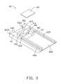
FIG. 3 is an enlarged view of an ejection device of the mobile communications device of FIG. 1.
FIG. 4 is an enlarged view of a groove member of the mobile communications device of FIG. 1.
FIG. 5 is an enlarged view of a hook device of the mobile communications device of FIG. 1.
FIG. 6 is an portion sectional view of the groove member of FIG. 4 when the groove member is ejected.
FIG. 7 is an portion sectional view of the groove member of FIG. 4 when the groove member is engaged with the mobile communications device.
DETAILED DESCRIPTION
Referring to FIG. 1, a mobile communications device 1 is disclosed. The mobile communications device 1 includes a front cover 10, a main body 20, and a back cover 30. In the exemplary embodiment, the front cover 10, the main body 20, and the back cover 30 are rectangular, and can be connected by splicing.
Referring to FIGS. 2-5, the back cover 30 includes an inner surface 31 and a sidewall 32. A first through hole 321 and a hatch 322 are formed in the sidewall 32.
The mobile communications device 1 further includes an ejection device 40, a groove member 90, a hook device 50, a first elastic device 60, and a torsion spring 70. The ejection device 40 is fixed to the inner surface 31 of the back cover 30. The ejection device 40 includes a resilient wall 410, a first groove 423 and an electromagnet 43. The elastic wall 410 protrudes from the surface of the ejection device 50. The first groove 423 is formed on the surface of the ejection device 40. The electromagnet 43 is fixed on the top surface of the first groove 423. The groove member 90 is slidably connected to the ejection device 40, and is aligned with the hatch 322. The groove member 90 is configured for receiving the subscriber identity module (SIM) card 100, and defines a hole 917. The hook device 50 is rotatably connected to the ejection device 40 and is positioned on the electromagnet 43. The hook device 50 includes a hook portion 52. One end of the first elasticity device 60 is fixed to the groove member 90. When the hook device 50 keeps in a first position, the hook portion 52 is engaged with the hole 917 of the groove member 90, so that, the first elastic device 60 is compressed by the groove member 90, and generates an elastic force relative to the groove member 90. The first elastic device 60 is configured for pushing the groove member 90 to move. The torsion spring 70 is fixed to the ejection device 40, and is configured for driving the hook device 50 to return to the first position. The torsion spring 70 includes a spring pole 71.
Referring to FIGS. 6-7, When the electromagnet 43 is electrified, the electromagnet 43 generates a magnetic field to attract the hook portion 52, as a result, the hook portion 52 becomes disengaged from the hole 917 of the groove member 90. Furthermore, the spring pole 71 of the torsion spring 70 moves along with the hook device 50, and thus, the torsion spring 70 becomes compressed, and generates an elastic force on the hook device 50. Due to the elastic force from the first elastic device 60, the groove member 90 is pushed along a longitudinal side of the ejection device 40 until a portion of the groove member 90 is exposed to the hatch 322, thus, the SIM card can be inserted or removed from the exposed groove member 90.
When the electromagnet 43 is powered off, the magnetic field disappears, and the hook device 50 returns to the first position due to the elastic force of the torsion spring 70. After rejecting or inserting the SIM Card 100, the exposed portion of groove member 90 is pushed into the mobile communications device 1 until that the hook portion 52 of the hook device 50 engages with the hole 917 of the groove member 90 again. For better understanding the disclosure, the following is a detailed exemplary embodiment.
The ejection device 40 is rectangular, and is fixed to the inner surface 31 of the back cover 30. The ejection device 40 includes an upper portion 41, a lower portion 42, and the electromagnet 43. The upper portion 41 and the lower portion 42 are rectangular, and the area of the upper portion 41 is less than that of the lower portion 42.
A second groove 424 is formed on the top surface of the upper portion 41. Sliding grooves 425, 426 are formed on each side of the second groove 424 correspondingly. The sliding grooves 425, 426 are configured for providing a slideway for the groove member 90. A second through hole 401 is formed on the top surface of the second groove 424. A resilient wall 410 is formed on one sidewall of the upper portion 41 adjacent to the second through hole 401. The resilient wall 410 defines holes 411, 412 in its two ends correspondingly. The holes 411, 412 extend along a longitudinal side of the upper portion 41. A hollow portion 413 is formed in a center of one sidewall of the upper portion 41, and is configured for receiving a switch device 80.
A first positioning pole 421 and a second positioning pole 422 protrudes from two ends of the one sidewall of the lower portion 42 correspondingly. In the exemplary embodiment, the first positioning pole 421 includes a hole 4210, and the second positioning pole 422 includes a hole 4220. The holes 4210, 4220 extend along a transverse side of the lower portion 42. A first groove 423 is formed on the top surface of the lower portion 42. In the exemplary embodiment, the width of the first groove 423 is substantially equal to the distance between the first positioning pole 421 and the second positioning pole 422. The electromagnet 43 is a rectangular, and is fixed on the top surface of the first groove 423.
The groove member 90 is a rectangular, and includes a main body 91 and a connector 92. A third groove 910 is formed on the top surface of the main body 91, and is configured for receiving the SIM card 100. Protrusions 920, 921 protrudes from two ends of one sidewall of the main body 91 away from the third groove 910 respectively. Sliding bars 930, 931 along a transverse side of the main body 91 are extended from the two ends of the sidewall respectively. The sliding bars 930, 931 are positioned on the sliding grooves 425, 426 of the upper portion 41 correspondingly, as a result, the groove member 90 slides on the second groove 424. The hole 917 is formed on the top surface of the main body 91. When the groove member 90 is entirely received into the second groove 424, the hole 917 is aligned with the second through hole 401 of the upper portion 41. The connector 92 is electronically connected to the SIM card 100.
The hook device 50 is rotatably connected to the lower portion 42 of the ejection device 40. The hook device 50 includes a main body 51, a hook portion 52, protrusions 54, 55, and an axis 56. The hook portion 52 protrudes from the top surface of the main body 51. In the exemplary embodiment, the hook portion 52 is made of metal, and is attracted by the electromagnet 43 when the electromagnet 43 is electrified. In another embodiment, the hook device 50 further includes a sheet metal 53, which is fixed to the bottom surface of the hook portion 52, and is attracted by the electromagnet 43 when the electromagnet 43 is electrified. The protrusions 54, 55 are extended from two ends of one sidewall of the main body 51 away from the hook portion 52 respectively. Holes 540, 550 along a transverse side of the main body 51 are formed on the protrusions 54, 55 respectively. The axis 56 is passed through the holes 4210, 540, 550, and 4220, so as to make the hook device 50 to rotatably connect to the ejection device 40.
The first elasticity device 60 includes a baffle 61, a first axis 62, and a second axis 63. The first axis 62 and the second axis 63 are fixed to the same side of the baffle 61. Springs 621, 631 are coiled around the first axis 62 and the second axis 63 correspondingly.
The torsion spring 70 includes an elastic pole 71, and two spring portions 72, 73. The spring portions 72, 73 are formed on the end of the elastic pole 71, and are coiled around the axis 56 of the hook device 50.
The switch device 80 includes a first switch 81 and a second switch 82. The first switch 81 is received into the first through hole 321, and is configured for powering the electromagnet 43. The second switch 82 is positioned on the hollow portion 413 of the upper portion 41, and is configured for discontinuing power to the electromagnet 43. The first switch 81 and the second switch 82 are connected in series with the electromagnet 43. In the exemplary embodiment, the first switch 81 and the second switch 82 are automatic reset switches. When the first switch 81 and the second switch 82 are triggered, the first switch 81 and the second switch 82 will automatically reset after a predetermined time.
When assembling the mobile communications device 1, first, the first switch 81 is received into the first through hole 321, and the second switch 82 is mounted on the hollow portion 413 of the upper portion 41. The spring portions 72, 73 of the torsion spring 70 are coiled around the axis 56, and positioned between the protrusion 54 and the protrusion 55. The elastic pole 71 of the torsion spring 70 resists against the bottom surface of the main body 51, and the end of the spring portion 72, 73 are fixed to the lower portion 42. The axis 56 is passed through the holes 4210, 540, 550, 4220; as a result, the torsion spring 70 and the hook device 50 are rotatably connected to the lower portion 42. When the groove member 90 is pushed into the second groove 424 along the hatch 322, ends of the first axis 62 and the second axis 63 away from the baffle 61 are fixed to the protrusions 920, 921 of the groove member 90 correspondingly. The baffle 61 is taken away, another ends of the first axis 62 and the second axis 63 are passed through the holes 411, 412 correspondingly, and the baffle 61 is fixed to another end of the first axis 62 and the second axis 63 again, as a result, the first elasticity device 60 is fixed to the groove member 90. Simultaneously, users continues to compress the groove member 90, so as to compress the first elasticity device 60, as a result, the hook portion 52 is passed through the hole 917 and is engaged with one sidewall of the hole 917. The main body 20 and the front cover 10 cooperate with the back cover 30 to form the mobile communications device 1.
Referring to FIG. 6, when rejecting or inserting the SIM card 100, the first switch 81 is actuated to electrify the electromagnet 43 as a result the electromagnet 43 generates the magnetic field. The magnetic field attracts the hook portion 52 of the hook device 50 or the sheet metal 53 to adjacent to the electromagnet 43; as a result, the hook portion 52 is disengaged from the groove member 90. The spring pole 71 of the torsion spring 70 moves along with the hook device 50, accordingly, the torsion spring 70 is compressed to generate an elastic force relative to the hook device 50. Due to the elastic force of first elasticity device 60, the groove member 90 is pushed along a longitudinal side of the ejection device 40 until that a portion of the groove member 90 is exposed to the hatch 322, and thus, the user can directly reject or insert the SIM card out of or into the exposed groove member 90. During the movement of the groove member 90, the baffle 61 moves along with the groove member 90 until the second switch 82 is triggered. Due to the second switch 82 is triggered, the electromagnet 43 is powered off, and the magnetic field disappears, the hook device 50 resumes the initial position by the elastic force of the torsion spring 70.
Referring to FIG. 7, after rejecting or inserting the SIM card 100, the exposed portion of the groove member 90 is pushed into the second groove 424 until that the hook portion 52 is engaged with the hole 917 of the groove member 90 again.
Although the present disclosure has been specifically described on the basis of the embodiments thereof, the disclosure is not to be construed as being limited thereto. Various changes or modifications may be made to the embodiments without departing from the scope and spirit of the disclosure.

Claims (9)

1. A mobile communications device comprising:
a back cover comprising an inner surface, a sidewall, and a hatch formed in the sidewall;
an ejection device fixed to the inner surface of the back cover, the ejection device comprising an resilient wall protruding from the surface of the ejection device, and an electromagnet;
a groove member slidably connected to the ejection device, and aligned with the hatch, and configured for putting in a subscriber identity module (SIM) card; the groove member defining a hole;
a hook device rotatably connected to the ejection device, and positioned above the electromagnet, and the hook device comprising a hook portion, wherein, when the hook device keeps in a first position, the hook portion is engaged with the hole of the groove member;
a first elastic device fixed to the groove member, and configured for pushing the groove member to move; and
a torsion spring fixed to the ejection device, and configured for driving the hook device to return to first position;
wherein, when the electromagnet is electrified to generate a magnetic field, the magnetic field attracts the hook portion to move towards the electromagnet, thereby, the hook device becomes disengaged from the groove member, and the groove member is pushed to expose via the hatch due to an elastic force of the first elastic device.
2. The mobile communications device as described in claim 1, wherein the ejection comprises an upper portion and a lower portion, the resilient wall protrudes from the top surface of the upper portion, a first groove is formed on the top surface of the lower portion, and the electromagnet is fixed in the first groove.
3. The mobile communications device as described in claim 2, further comprising a switch device, which comprises a first switch, wherein a first through hole is formed on the sidewall of the back cover; and the first switch is received into the first through hole, and is configured for electrifying the electromagnet.
4. The mobile communications device as described in claim 3, wherein a hollow portion is formed in one sidewall of the upper portion;
the switch device further comprises a second switch, which is mounted on the hollow portion; and
the first elastic device further comprises a baffle, during the time the groove member moves to the hatch, the baffle moves along with the groove member to trigger the second switch.
5. The mobile communications device as described in claim 4, wherein the first switch and the second switch are automatic reset switches, when being triggered, the first switch and the second switch automatically reset after a predetermined time.
6. The mobile communications device as described in claim 1, wherein the hook portion is made of metal.
7. The mobile communications device as described in claim 1, wherein the hook device further comprises a sheet metal, which is fixed to the bottom surface of the hook portion.
8. The mobile communications device as described in claim 2, wherein the hook device further comprises a main body and an axis, protrusions extend from two ends of one sidewall of the main body away from the hook portion correspondingly, holes are formed on the protrusions along a transverse side of the main body;
a first positioning pole and a second positioning pole protrude from two ends of the one sidewall of the lower portion correspondingly; holes along a transverse side of the lower portion are formed on the first positioning pole and the second positioning pole correspondingly;
the protrusions are positioned between the first positioning pole and the second positioning pole, the axis is passed through the above four holes, thereby, the hook device is rotatably connected to the lower portion of the ejection device.
9. The mobile communications device as described in claim 2, wherein a second groove is formed on the top surface of the upper portion, a sliding groove is formed on each side of the second groove correspondingly, and is configured for providing a slideway for the groove member;
sliding bars along a transverse side of the main body are extended from the two ends of the sidewall correspondingly, and the sliding bars are positioned on the sliding grooves.
US12/604,344 2009-09-18 2009-10-22 Mobile communications device Expired - Fee Related US8070500B2 (en)

Applications Claiming Priority (3)

Application Number Priority Date Filing Date Title
CN200910307331.9 2009-09-18
CN200910307331 2009-09-18
CN2009103073319A CN102025806B (en) 2009-09-18 2009-09-18 Mobile communication device

Publications (2)

Publication Number Publication Date
US20110070929A1 US20110070929A1 (en) 2011-03-24
US8070500B2 true US8070500B2 (en) 2011-12-06

Family

ID=43757082

Family Applications (1)

Application Number Title Priority Date Filing Date
US12/604,344 Expired - Fee Related US8070500B2 (en) 2009-09-18 2009-10-22 Mobile communications device

Country Status (2)

Country Link
US (1) US8070500B2 (en)
CN (1) CN102025806B (en)

Cited By (7)

* Cited by examiner, † Cited by third party
Publication number Priority date Publication date Assignee Title
USD669448S1 (en) * 2011-08-10 2012-10-23 Samsung Electronics Co., Ltd. Mobile phone
US20140004728A1 (en) * 2012-07-02 2014-01-02 Lotes Co., Ltd. Receptacle connector
US20140179135A1 (en) * 2012-12-25 2014-06-26 Hon Hai Precision Industry Co., Ltd. Ejecting device for storage card
USD742348S1 (en) * 2013-02-12 2015-11-03 Lg Electronics Inc. Mobile phone
USD747285S1 (en) * 2013-02-12 2016-01-12 Lg Electronics Inc. Mobile phone
USD767523S1 (en) * 2014-10-03 2016-09-27 Hisense Mobile Communications Technology Co., Ltd. Mobile phone
US20170142853A1 (en) * 2015-11-13 2017-05-18 Yong-Peng LI Protective cover for portable electronic device

Families Citing this family (46)

* Cited by examiner, † Cited by third party
Publication number Priority date Publication date Assignee Title
USD672327S1 (en) * 2010-12-28 2012-12-11 Samsung Electronics Co., Ltd. Portable telephone
USD720713S1 (en) 2012-10-19 2015-01-06 Zte Corporation Mobile phone
TWI567528B (en) 2013-01-10 2017-01-21 佳能企業股份有限公司 Sliding mechanism and electronic device using the same
CN103929573A (en) * 2013-01-15 2014-07-16 佳能企业股份有限公司 Slide knob mechanism and electronic device applying mechanism
CN103151645B (en) * 2013-02-07 2015-02-11 上海华勤通讯技术有限公司 Nano-sim (subscriber identity module) card holder and mobile terminal with nano-sim card holder
JP1485872S (en) * 2013-05-10 2016-05-30
CN104158923A (en) * 2013-05-15 2014-11-19 中国电信股份有限公司 Mobile terminal
USD739368S1 (en) * 2013-07-09 2015-09-22 Samsung Display Co., Ltd. Mobile phone
USD733674S1 (en) * 2013-09-18 2015-07-07 Sony Mobile Communications Ab Mobile phone
USD761749S1 (en) * 2013-10-07 2016-07-19 Lg Electronics Inc. Mobile phone
CN104600490B (en) * 2013-10-31 2017-01-25 中祥电子商务股份有限公司 Mobile terminal with fixing device
USD777129S1 (en) * 2014-01-10 2017-01-24 Huawei Device Co., Ltd. Mobile phone
USD746283S1 (en) * 2014-02-03 2015-12-29 Lg Electronics Inc. Tablet computer
USD746284S1 (en) * 2014-02-03 2015-12-29 Lg Electronics Inc. Tablet computer
JP1518564S (en) * 2014-03-19 2015-03-02
JP1518563S (en) * 2014-03-19 2015-03-02
USD763240S1 (en) * 2014-07-01 2016-08-09 Google Inc. Portion of a handheld device
CN105406219A (en) * 2014-09-10 2016-03-16 富泰华精密电子(郑州)有限公司 Chip card clamping mechanism
CN105430120A (en) * 2014-09-16 2016-03-23 中兴通讯股份有限公司 Mobile phone plug pop-out system, mobile phone and mobile phone plug pop-out method
CN105449396A (en) * 2014-09-24 2016-03-30 富泰华工业(深圳)有限公司 Mobile terminal
CN104683514A (en) * 2015-02-05 2015-06-03 小米科技有限责任公司 Card slot, mobile terminal, and card support pop-out method and device
USD794594S1 (en) * 2015-04-08 2017-08-15 Lg Electronics Inc. Mobile phone
USD793982S1 (en) * 2015-04-08 2017-08-08 Lg Electronics Inc. Mobile phone
USD795828S1 (en) * 2015-04-08 2017-08-29 Lg Electronics Inc. Mobile phone
USD797071S1 (en) * 2015-04-08 2017-09-12 Lg Electronics Inc. Mobile phone
USD795827S1 (en) * 2015-04-08 2017-08-29 Lg Electronics Inc. Mobile phone
USD793981S1 (en) * 2015-04-08 2017-08-08 Lg Electronics Inc. Mobile phone
USD795829S1 (en) * 2015-04-08 2017-08-29 Lg Electronics Inc. Mobile phone
USD798260S1 (en) * 2015-04-15 2017-09-26 Lg Electronics Inc. Mobile phone
USD797072S1 (en) * 2015-04-15 2017-09-12 Lg Electronics Inc. Mobile phone
USD823273S1 (en) * 2015-06-10 2018-07-17 Fairphone B.V. Mobile phone
CN105098505B (en) * 2015-07-16 2017-08-11 努比亚技术有限公司 The mobile terminal of card connector and the application card connector
USD793985S1 (en) * 2015-12-18 2017-08-08 Samsung Electronics Co., Ltd. Electronic device
USD825511S1 (en) * 2015-12-22 2018-08-14 Lg Electronics Inc. Mobile phone
USD908692S1 (en) * 2016-06-14 2021-01-26 Amazon Technologies, Inc. Electronic device
TWD202311S (en) * 2017-03-18 2020-01-21 大陸商廣東歐珀移動通信有限公司 Part of mobile phone
USD908693S1 (en) * 2017-03-29 2021-01-26 Amazon Technologies, Inc. Electronic device
CN107370199A (en) * 2017-06-26 2017-11-21 上海与德科技有限公司 USB male joint, female and power supply, charging terminal and charging connection control method
TWD196407S (en) * 2017-06-28 2019-03-11 大陸商廣東歐珀移動通信有&#x9 Mobile phone
CN107517064A (en) * 2017-07-27 2017-12-26 努比亚技术有限公司 A kind of Kato structure
CN109391280A (en) * 2017-08-04 2019-02-26 中兴通讯股份有限公司 Groove device and terminal
CN110875752B (en) * 2018-09-04 2021-09-10 青岛海信移动通信技术股份有限公司 Card lid structure and mobile terminal
USD909326S1 (en) * 2018-09-30 2021-02-02 Beijing Xiaomi Mobile Software Co., Ltd. Mobile phone
CN109888556B (en) * 2019-01-21 2020-11-13 上海摩软通讯技术有限公司 Card support locking and ejecting mechanism, card support fixing device and electronic equipment
USD883947S1 (en) * 2019-01-24 2020-05-12 Hmd Global Oy Mobile phone
USD923619S1 (en) * 2019-10-22 2021-06-29 Amazon Technologies, Inc. Electronic device

Citations (7)

* Cited by examiner, † Cited by third party
Publication number Priority date Publication date Assignee Title
US6109941A (en) * 1999-02-02 2000-08-29 Hon Hai Precision Ind. Co., Ltd. Ejector mechanism for a memory card connector
US6123560A (en) * 1998-12-31 2000-09-26 Hon Hai Precision Ind. Co., Ltd. Ejection mechanism of electronic card connector
US6652301B2 (en) * 2001-12-28 2003-11-25 J.S.T. Mfg. Co., Ltd. Ejector mechanism for card connector
US6796816B2 (en) * 2002-08-23 2004-09-28 Hon Hai Precision Ind. Co., Ltd. Card connector having strengthened ejection mechanism
US6857886B2 (en) * 2003-06-06 2005-02-22 Hon Hai Precision Ind. Co., Ltd. Electronic card connector
US7192292B1 (en) * 2006-03-03 2007-03-20 Cheng Uei Precision Industry Co., Ltd. Card connector having improved supporting structure for ejecting mechanism
US7927116B2 (en) * 2008-11-13 2011-04-19 Molex Incorporated Electrical card connector with improved ejection mechanism

Family Cites Families (1)

* Cited by examiner, † Cited by third party
Publication number Priority date Publication date Assignee Title
KR101033587B1 (en) * 2004-05-15 2011-05-11 엘지전자 주식회사 A Semi-auto Slide Device, a Dual Slide Device of Cellular Phone and Cellualar Phones having that

Patent Citations (7)

* Cited by examiner, † Cited by third party
Publication number Priority date Publication date Assignee Title
US6123560A (en) * 1998-12-31 2000-09-26 Hon Hai Precision Ind. Co., Ltd. Ejection mechanism of electronic card connector
US6109941A (en) * 1999-02-02 2000-08-29 Hon Hai Precision Ind. Co., Ltd. Ejector mechanism for a memory card connector
US6652301B2 (en) * 2001-12-28 2003-11-25 J.S.T. Mfg. Co., Ltd. Ejector mechanism for card connector
US6796816B2 (en) * 2002-08-23 2004-09-28 Hon Hai Precision Ind. Co., Ltd. Card connector having strengthened ejection mechanism
US6857886B2 (en) * 2003-06-06 2005-02-22 Hon Hai Precision Ind. Co., Ltd. Electronic card connector
US7192292B1 (en) * 2006-03-03 2007-03-20 Cheng Uei Precision Industry Co., Ltd. Card connector having improved supporting structure for ejecting mechanism
US7927116B2 (en) * 2008-11-13 2011-04-19 Molex Incorporated Electrical card connector with improved ejection mechanism

Cited By (10)

* Cited by examiner, † Cited by third party
Publication number Priority date Publication date Assignee Title
USD669448S1 (en) * 2011-08-10 2012-10-23 Samsung Electronics Co., Ltd. Mobile phone
US20140004728A1 (en) * 2012-07-02 2014-01-02 Lotes Co., Ltd. Receptacle connector
US8747127B2 (en) * 2012-07-02 2014-06-10 Lotes Co., Ltd. Receptacle connector
US20140179135A1 (en) * 2012-12-25 2014-06-26 Hon Hai Precision Industry Co., Ltd. Ejecting device for storage card
US9135527B2 (en) * 2012-12-25 2015-09-15 Hon Hai Precision Industry Co., Ltd. Ejecting device for storage card
USD742348S1 (en) * 2013-02-12 2015-11-03 Lg Electronics Inc. Mobile phone
USD747285S1 (en) * 2013-02-12 2016-01-12 Lg Electronics Inc. Mobile phone
USD767523S1 (en) * 2014-10-03 2016-09-27 Hisense Mobile Communications Technology Co., Ltd. Mobile phone
US20170142853A1 (en) * 2015-11-13 2017-05-18 Yong-Peng LI Protective cover for portable electronic device
US9992887B2 (en) * 2015-11-13 2018-06-05 Hong Fu Jin Precision Industry (Taiyuan) Co Protective cover for portable electronic device

Also Published As

Publication number Publication date
CN102025806A (en) 2011-04-20
US20110070929A1 (en) 2011-03-24
CN102025806B (en) 2013-05-08

Similar Documents

Publication Publication Date Title
US8070500B2 (en) Mobile communications device
US8460019B2 (en) Card connector with separable card tray
US7407414B2 (en) Surface contact card holder
US8432682B2 (en) Electronic device with slot cover ejection mechanism
US9135527B2 (en) Ejecting device for storage card
US8672229B2 (en) Electronic module holder with sliding door
US8121644B2 (en) Mobile phone capable of automatically handling smart card
US20170026070A1 (en) Smartphone case with concealed card cache, and method of using same
US7314390B1 (en) Drawer-type card connector
US20070037431A1 (en) Surface contact card holder
US8902602B2 (en) Communication device and ejection mechanism
JP2007234472A (en) Card connector
CN104332766A (en) Connector and mobile terminal equipment with same
US9336461B2 (en) Electronic card connector having ejecting mechanism
US8203829B2 (en) Battery cover assembly and electronic device utilizing the same
KR101833722B1 (en) Connector Apparatus with Receiving Part for Card
US7861758B2 (en) Push-button controlled correction tape
EP3197134B1 (en) Mobile terminal stopper ejection system, mobile terminal and mobile terminal stopper ejection method
KR20110048081A (en) Connector
US20140011381A1 (en) Card connector with card ejection mechanism
KR101657201B1 (en) Socket connector for Nano-SIM and Micro-SD Combo lever type
US8367237B2 (en) Electronic device with battery ejection mechanism
US8783797B2 (en) Electronic device having card holder
KR101343069B1 (en) Improved connector for memory card
US20080090458A1 (en) Electrical card connector having ejection mechanism

Legal Events

Date Code Title Description
AS Assignment

Owner name: HONG FU JIN PRECISION INDUSTRY (SHENZHEN) CO., LTD

Free format text: ASSIGNMENT OF ASSIGNORS INTEREST;ASSIGNOR:LI, XIONG;REEL/FRAME:023412/0382

Effective date: 20090727

Owner name: HON HAI PRECISION INDUSTRY CO., LTD., TAIWAN

Free format text: ASSIGNMENT OF ASSIGNORS INTEREST;ASSIGNOR:LI, XIONG;REEL/FRAME:023412/0382

Effective date: 20090727

REMI Maintenance fee reminder mailed
LAPS Lapse for failure to pay maintenance fees
STCH Information on status: patent discontinuation

Free format text: PATENT EXPIRED DUE TO NONPAYMENT OF MAINTENANCE FEES UNDER 37 CFR 1.362

FP Lapsed due to failure to pay maintenance fee

Effective date: 20151206