US8073018B2 - Laser pulse generating apparatus and method - Google Patents
Laser pulse generating apparatus and method Download PDFInfo
- Publication number
- US8073018B2 US8073018B2 US12/665,636 US66563608A US8073018B2 US 8073018 B2 US8073018 B2 US 8073018B2 US 66563608 A US66563608 A US 66563608A US 8073018 B2 US8073018 B2 US 8073018B2
- Authority
- US
- United States
- Prior art keywords
- pulse
- laser beam
- light guide
- guide path
- optical
- Prior art date
- Legal status (The legal status is an assumption and is not a legal conclusion. Google has not performed a legal analysis and makes no representation as to the accuracy of the status listed.)
- Expired - Fee Related
Links
Images


Classifications
-
- H—ELECTRICITY
- H01—ELECTRIC ELEMENTS
- H01S—DEVICES USING THE PROCESS OF LIGHT AMPLIFICATION BY STIMULATED EMISSION OF RADIATION [LASER] TO AMPLIFY OR GENERATE LIGHT; DEVICES USING STIMULATED EMISSION OF ELECTROMAGNETIC RADIATION IN WAVE RANGES OTHER THAN OPTICAL
- H01S5/00—Semiconductor lasers
- H01S5/10—Construction or shape of the optical resonator, e.g. extended or external cavity, coupled cavities, bent-guide, varying width, thickness or composition of the active region
- H01S5/14—External cavity lasers
- H01S5/146—External cavity lasers using a fiber as external cavity
- H01S5/147—External cavity lasers using a fiber as external cavity having specially shaped fibre, e.g. lensed or tapered end portion
-
- H—ELECTRICITY
- H01—ELECTRIC ELEMENTS
- H01S—DEVICES USING THE PROCESS OF LIGHT AMPLIFICATION BY STIMULATED EMISSION OF RADIATION [LASER] TO AMPLIFY OR GENERATE LIGHT; DEVICES USING STIMULATED EMISSION OF ELECTROMAGNETIC RADIATION IN WAVE RANGES OTHER THAN OPTICAL
- H01S3/00—Lasers, i.e. devices using stimulated emission of electromagnetic radiation in the infrared, visible or ultraviolet wave range
- H01S3/10—Controlling the intensity, frequency, phase, polarisation or direction of the emitted radiation, e.g. switching, gating, modulating or demodulating
- H01S3/10038—Amplitude control
- H01S3/10046—Pulse repetition rate control
-
- H—ELECTRICITY
- H01—ELECTRIC ELEMENTS
- H01S—DEVICES USING THE PROCESS OF LIGHT AMPLIFICATION BY STIMULATED EMISSION OF RADIATION [LASER] TO AMPLIFY OR GENERATE LIGHT; DEVICES USING STIMULATED EMISSION OF ELECTROMAGNETIC RADIATION IN WAVE RANGES OTHER THAN OPTICAL
- H01S3/00—Lasers, i.e. devices using stimulated emission of electromagnetic radiation in the infrared, visible or ultraviolet wave range
- H01S3/10—Controlling the intensity, frequency, phase, polarisation or direction of the emitted radiation, e.g. switching, gating, modulating or demodulating
- H01S3/106—Controlling the intensity, frequency, phase, polarisation or direction of the emitted radiation, e.g. switching, gating, modulating or demodulating by controlling devices placed within the cavity
- H01S3/1067—Controlling the intensity, frequency, phase, polarisation or direction of the emitted radiation, e.g. switching, gating, modulating or demodulating by controlling devices placed within the cavity using pressure or deformation
-
- H—ELECTRICITY
- H01—ELECTRIC ELEMENTS
- H01S—DEVICES USING THE PROCESS OF LIGHT AMPLIFICATION BY STIMULATED EMISSION OF RADIATION [LASER] TO AMPLIFY OR GENERATE LIGHT; DEVICES USING STIMULATED EMISSION OF ELECTROMAGNETIC RADIATION IN WAVE RANGES OTHER THAN OPTICAL
- H01S5/00—Semiconductor lasers
- H01S5/005—Optical components external to the laser cavity, specially adapted therefor, e.g. for homogenisation or merging of the beams or for manipulating laser pulses, e.g. pulse shaping
- H01S5/0064—Anti-reflection components, e.g. optical isolators
-
- H—ELECTRICITY
- H01—ELECTRIC ELEMENTS
- H01S—DEVICES USING THE PROCESS OF LIGHT AMPLIFICATION BY STIMULATED EMISSION OF RADIATION [LASER] TO AMPLIFY OR GENERATE LIGHT; DEVICES USING STIMULATED EMISSION OF ELECTROMAGNETIC RADIATION IN WAVE RANGES OTHER THAN OPTICAL
- H01S5/00—Semiconductor lasers
- H01S5/02—Structural details or components not essential to laser action
- H01S5/022—Mountings; Housings
- H01S5/0225—Out-coupling of light
- H01S5/02251—Out-coupling of light using optical fibres
-
- H—ELECTRICITY
- H01—ELECTRIC ELEMENTS
- H01S—DEVICES USING THE PROCESS OF LIGHT AMPLIFICATION BY STIMULATED EMISSION OF RADIATION [LASER] TO AMPLIFY OR GENERATE LIGHT; DEVICES USING STIMULATED EMISSION OF ELECTROMAGNETIC RADIATION IN WAVE RANGES OTHER THAN OPTICAL
- H01S5/00—Semiconductor lasers
- H01S5/04—Processes or apparatus for excitation, e.g. pumping, e.g. by electron beams
- H01S5/042—Electrical excitation ; Circuits therefor
- H01S5/0428—Electrical excitation ; Circuits therefor for applying pulses to the laser
-
- H—ELECTRICITY
- H01—ELECTRIC ELEMENTS
- H01S—DEVICES USING THE PROCESS OF LIGHT AMPLIFICATION BY STIMULATED EMISSION OF RADIATION [LASER] TO AMPLIFY OR GENERATE LIGHT; DEVICES USING STIMULATED EMISSION OF ELECTROMAGNETIC RADIATION IN WAVE RANGES OTHER THAN OPTICAL
- H01S5/00—Semiconductor lasers
- H01S5/06—Arrangements for controlling the laser output parameters, e.g. by operating on the active medium
- H01S5/065—Mode locking; Mode suppression; Mode selection ; Self pulsating
- H01S5/0656—Seeding, i.e. an additional light input is provided for controlling the laser modes, for example by back-reflecting light from an external optical component
-
- H—ELECTRICITY
- H01—ELECTRIC ELEMENTS
- H01S—DEVICES USING THE PROCESS OF LIGHT AMPLIFICATION BY STIMULATED EMISSION OF RADIATION [LASER] TO AMPLIFY OR GENERATE LIGHT; DEVICES USING STIMULATED EMISSION OF ELECTROMAGNETIC RADIATION IN WAVE RANGES OTHER THAN OPTICAL
- H01S5/00—Semiconductor lasers
- H01S5/06—Arrangements for controlling the laser output parameters, e.g. by operating on the active medium
- H01S5/068—Stabilisation of laser output parameters
- H01S5/06821—Stabilising other output parameters than intensity or frequency, e.g. phase, polarisation or far-fields
Definitions
- the present invention relates to a laser pulse generating apparatus and method for generating a laser beam pulse.
- Patent Document 1 discloses a laser pulse generating apparatus for feeding a portion of emission light back to a semiconductor laser by using a polarization maintaining optical fiber.
- Non-Patent Document 1 discloses an accurate measurement method of OFDR (Optical Frequency Domain Reflectometry) using an optical feedback path length where polarization is maintained by using a polarization maintaining FBG (Fiber Bragg Grading).
- OFDR Optical Frequency Domain Reflectometry
- FBG Fiber Bragg Grading
- Patent Document 1 Japanese Patent Laid-Open No. 2007-35661
- Non-Patent Document 1 Omichi et al., “Polarization Division Multiplexing Measurement of Optical Frequency Domain Reflectometry Using Polarization Maintaining Fiber Bragg Grating” Proceedings 1 of the 2008 IEICE General Conference, Kitakyushu, C-3-78, Mar. 18 to 21, 2008
- a laser pulse generating apparatus including: a laser beam generating device; a driving device; a first light guide path; an optical filter; a second light guide path; and a reflecting device, wherein the laser beam generating device is driven to generate a laser beam having a predetermined wavelength spectrum and emit the laser beam to the first light guide path, the driving device drives the laser beam generating device to generate a pulse of the laser beam, the first light guide path guides the pulse between the laser beam generating device and the optical filter, the optical filter transmits a predetermined wavelength spectrum of the pulse entering from the first light guide path to emit the pulse having the predetermined wavelength spectrum to the second light guide path, and transmits a predetermined wavelength spectrum of the pulse entering from the second light guide path to emit the pulse having the predetermined wavelength spectrum to the first light guide path, the second light guide path guides the pulse between the optical filter
- a laser pulse generating apparatus including: a laser beam generating device; a driving device; a first light guide path; and an optical reflection filter, wherein the laser beam generating device is driven to generate a laser beam having a predetermined wavelength spectrum and emit the laser beam to the first light guide path, the driving device drives the laser beam generating device to generate a pulse of the laser beam, the first light guide path guides the pulse between the laser beam generating device and the optical reflection filter, and the optical reflection filter reflects only a portion of optical power of the pulse having a predetermined wavelength spectrum entering from the first light guide path to feed the portion back to the laser beam generating device via the first light guide path.
- a semiconductor laser device a polarization maintaining optical fiber, a polarization maintaining optical fiber, an optical reflection filter having bandpass characteristics using an FBG whose passband can be changed by changing a tension, a polarization maintaining optical fiber, a reflecting device, a normal optical fiber, and an optical isolator are connected in the above order so as to guide a laser beam via a connector or the like, if necessary.
- a driving circuit for driving the semiconductor laser device allows the semiconductor laser device to generate a pulse of short duration and emit the pulse to the polarization maintaining optical fiber.
- the pulse emitted from the semiconductor laser device is guided to the optical reflection filter via the optical fiber connected to the polarization maintaining optical fiber.
- the optical reflection filter performs filtering by transmitting a specific component of the wavelength spectrum broadened by chirping of the pulse, and feeds a portion of the optical power of the filtered pulse back to the semiconductor laser device via the polarization maintaining optical fiber.
- the optical reflection filter also transmits a large portion of the optical power of the pulse without reflecting it, and outputs the large portion to the outside via the optical fiber and the optical isolator.
- a semiconductor laser device a polarization maintaining optical fiber, an optical filter, a polarization maintaining optical fiber, a normal optical fiber, and an optical isolator are connected in the above order so as to guide a laser beam via a connector, if necessary.
- the optical filter used in the embodiment has both the function as a bandpass filter using an FBG whose passband can be changed by changing a tension, and the function of reflecting a portion of the optical power of an entering pulse.
- a driving circuit for driving the semiconductor laser device allows the semiconductor laser device to generate a pulse of short duration and emit the pulse to the polarization maintaining optical fiber.
- the pulse emitted from the semiconductor laser device is guided to the optical filter via the optical fiber connected to the polarization maintaining optical fiber.
- the optical filter filters the pulse to feed a portion thereof back to the semiconductor laser device, and outputs the remaining portion to the outside via the polarization maintaining optical fiber, the normal optical fiber and the optical isolator.
- the laser beam pulse having the same quality as that of the above embodiment of the laser pulse generating apparatus according to the present application can be also obtained.
- FIGS. 1A and 1B are views illustrating an example in which a pulse of a laser beam is fed back to a semiconductor laser device, wherein FIG. 1A illustrates a case in which a pulse repetition rate per unit time is relatively low, and FIG. 1B illustrates a case in which a pulse repetition rate per unit time is relatively high;
- FIGS. 2A and 2B are views illustrating an example of a pulse waveform obtained according to the presence or absence of the feedback of the pulse of the laser beam to the semiconductor laser device, wherein FIG. 2A illustrates a pulse waveform obtained when the pulse of the laser beam is not fed back to the semiconductor laser device, and FIG. 2B illustrates a pulse waveform obtained when the pulse of the laser beam is fed back to the semiconductor laser device;
- FIG. 3 is a graph illustrating the relationship between a pulse repetition rate per one second output from the semiconductor laser device and a jitter value, in which a plurality of points indicated by squares represent a group of jitter values and frequencies under conditions to obtain a preferable pulse quality in a given optical feedback fiber length, and a plurality of points indicated by star marks represent a group of jitter values and frequencies under conditions to obtain a preferable pulse quality in a feedback fiber length slightly longer than the given optical feedback fiber length;
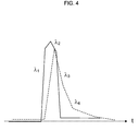
- FIG. 4 is a view illustrating an example of the schematic shape (a solid line) of a desired waveform of the pulse of the laser beam, and the schematic shape (a dashed line) of an actual waveform of the pulse obtained by feeding back the pulse as described with reference to FIGS. 1 to 3 ;
- FIGS. 5A and 5B are views illustrating the schematic shape of a wavelength spectrum of the pulse of the laser beam fed back to the semiconductor laser device, wherein FIG. 5A illustrates a wavelength spectrum included in a pulse whose band is not limited, and FIG. 5B illustrates a wavelength spectrum included in a feedback pulse whose band is limited;
- FIG. 6 is a first view illustrating an embodiment of the present invention, which illustrates the configuration of a first laser pulse generating apparatus
- FIG. 7 is a view illustrating the operation of the first laser pulse generating apparatus shown in FIG. 6 ;
- FIG. 8 is a second view illustrating an embodiment of the present invention, which illustrates the configuration of a second laser pulse generating apparatus
- FIG. 9A is a view illustrating an example of the section of a timing adjustment unit shown in FIG. 8 ;
- FIG. 9B is a view illustrating an example of the configuration of an FBG filter;
- FIG. 10 is a view illustrating a method of adjusting the second laser pulse generating apparatus shown in FIG. 8 .
- FIGS. 1A and 1B are views illustrating an example in which a pulse of a laser beam is fed back to a semiconductor laser device.
- FIG. 1A illustrates a case in which a pulse repetition rate per unit time is relatively low
- FIG. 1B illustrates a case in which a pulse repetition rate per unit time is relatively high.
- FIGS. 2A and 2B are views illustrating an example of a pulse waveform obtained according to the presence or absence of the feedback of the pulse of the laser beam to the semiconductor laser device.
- FIG. 2A illustrates a pulse waveform obtained when the pulse of the laser beam is not fed back to the semiconductor laser device
- FIG. 2B illustrates a pulse waveform obtained when the pulse of the laser beam is fed back to the semiconductor laser device.
- the pulse can be fed back to the semiconductor laser device.
- the semiconductor laser device for example, a semiconductor laser diode that can be directly modulated by gain switching; a gain switched laser diode
- the pulse can be fed back to the semiconductor laser device.
- conditions are preferably satisfied using the same optical feedback path length in both the cases.
- time jitter (referred to as jitter below) generated in the pulse that is obtained when the pulse of the laser beam is not fed back to the semiconductor laser device as shown in FIG. 2A can be significantly reduced, so that a high quality pulse having a preferable waveform with no fluctuation in the timing and waveform of the repeatedly generated pulse can be obtained as shown in FIG. 2B .
- the wavelength of light to be injected into the semiconductor laser device from outside for the feedback falls within the range of wavelengths that resonate with the mode of each semiconductor laser resonator, the light cannot be effectively injected into the semiconductor laser device. However, since the pulse generated by the semiconductor laser device itself is fed back, the condition is basically satisfied.
- the optical power of the pulse of the laser beam fed back to the semiconductor laser device should be about a few microwatts, and the polarization of the laser beam should be maintained in a TE mode.
- the pulse of the laser beam can be fed back to the semiconductor laser device very easily and at a very low cost. Furthermore, the pulse of the laser beam can be significantly improved in quality.
- a graph shows the relationship between a pulse repetition rate per one second (unit GHz; referred to as pulse frequency below) output from the semiconductor laser device, and a jitter value (unit ps).
- a plurality of points indicated by squares in the graph represent a group of jitter values and frequencies under conditions to obtain a preferable pulse quality in a given optical feedback fiber length
- a plurality of points indicated by star marks in the graph represent a group of jitter values and frequencies under conditions to obtain a preferable pulse quality in a feedback fiber length slightly longer than the given optical feedback fiber length.
- the pulse frequency is 1 GHz and a 10-m polarization maintaining (PM) optical fiber (fiber-pigtail-code; optical path length 100 m) wound into a loop is used as the optical path, a pulse is fed back to a 100th pulse from the pulse.
- PM polarization maintaining
- the timing of feeding the pulse back to the semiconductor laser device can be adjusted. Accordingly, the pulse frequency can be adjusted to be slightly higher than 1 GHz or slightly lower than 1.01 GHz.
- the points indicated by the square marks represent a group of preferable conditions when no tension is applied to the optical fiber having a length of 1 m
- the points indicated by the star marks represent a group of preferable conditions when a small tension is applied to the optical fiber to extend the length.
- the groups of preferable conditions obtained when the tension is applied or is not applied to the optical fiber are slightly different from each other, and are repeatedly obtained.
- the pulse fed back to the semiconductor laser device increases the number of photons in the laser beam having a wavelength selected by an oscillator cavity, and electric charge fluctuations acting as the seed for oscillation of a laser beam having another wavelength and inducing stimulated emission of another wavelength are suppressed.
- FIG. 4 is a view illustrating an example of the schematic shape of a desired waveform of the pulse of the laser beam, and the schematic shape of an actual waveform of the pulse obtained by feeding back the pulse as described with reference to FIGS. 1 to 3 .
- the pulse of the laser beam is desired to have a symmetrical waveform at a turn-on portion and a turn-off portion as indicated by a solid line in FIG. 4 .
- the conventional pulse of the laser beam includes dynamic wavelength chirping shift due to the combination of fluctuations in carrier density and fluctuations in resonator length as indicated by a dashed line in FIG. 4 .
- the wavelength in the first half ( ⁇ 1 ) and the wavelength in the second half ( ⁇ 2 to ⁇ 4 ) of the pulse are slightly different from each other.
- the second half of the waveform of the pulse indicated by the dashed line in FIG. 4 is not symmetrical to the turn-on portion in the first half of the waveform of the pulse, and includes side robes and a pedestal whereby the turn-off portion is gently inclined.
- the chirping, and the side robes and the pedestal in the second half of the pulse caused by the chirping do not directly affect the quality of waveform shaping a lot in comparison with the original pulse width, turn-on and turn-off.
- the chirping, the side robes and the pedestal greatly affect the quality of waveform shaping when waveform processing for further reducing the pulse width is performed on the light pulse by linear compression by wavelength dispersion correction or nonlinear compression by spectral expansion since the chirping, the side robes and the pedestal become an obstacle to an ideal compression process.
- the pulse of the laser beam fed back to the semiconductor laser device also includes the difference in wavelength between the first half and the second half of the pulse, and the side robes and pedestal of the waveform as shown in FIG. 4 , the pulse fed back to the semiconductor laser device also affects the fluctuations in the wavelength and the waveform in the second half of the pulse generated by the semiconductor laser device.
- the desired waveform cannot be obtained only by directly feeding the pulse back to the semiconductor laser device as described with reference to FIGS. 1 to 3 .
- the wavelength of the pulse to be fed back to the semiconductor laser device is selected, so that the fluctuations in the wavelength and the waveform in the second half of the pulse generated by the semiconductor laser device as shown in FIG. 4 can be suppressed.
- FIGS. 5A and 5B are views illustrating the schematic shape of a wavelength spectrum of the pulse of the laser beam fed back to the semiconductor laser device.
- FIG. 5A illustrates a wavelength spectrum included in a pulse whose band is not limited
- FIG. 5B illustrates a wavelength spectrum included in a feedback pulse whose band is limited.
- only a wavelength spectrum component ⁇ 1 in the first half portion of the waveform of the pulse of FIG. 5B is selected from the pulse of the laser beam including wavelength spectrum components ⁇ 1 to ⁇ 4 as shown in FIG. 5A , and the pulse having the wavelength spectrum component ⁇ 1 is fed back to the semiconductor laser device.
- the waveform of the pulse turns on and turns off more steeply, and the difference in the wavelength between the first half and the second half of the pulse, and the side robes and pedestal of the waveform shown in FIG. 4 can be improved (the light pulse is closer to the transform limit).
- FIG. 6 is a first view illustrating an embodiment of the present invention, which illustrates the configuration of a first laser pulse generating apparatus 1 .
- the first laser pulse generating apparatus 1 includes a transmitter 10 (a driving device), a laser diode module (an LD module; a laser beam generating device) 12 , PM optical fibers 14 - 1 to 14 - 3 (first to fifth light guide paths), connectors 16 - 1 and 16 - 2 , any and normal optical fibers 18 - 1 and 18 - 2 , an optical filter 20 , a partial reflector 22 (a reflecting device), and an optical isolator 24 .
- the optical fibers 18 - 1 and 18 - 2 may be collectively referred to as the optical fibers 18 or the like.
- the transmitter 10 drives the LD module 12 to generate a laser beam pulse.
- the LD module 12 is a butterfly laser diode module that can be directly modulated by a gain switching method, a less-expensive and simple TOSA module, or a diode pumped solid state (DPSS) laser, for example, and is driven by the transmitter 10 to generate the laser beam pulse and emit the pulse to the PM optical fiber 14 .
- DPSS diode pumped solid state
- the LD module 12 also receives the pulse fed back via the PM optical fibers 14 - 1 to 14 - 3 and the optical filter 20 .
- the PM optical fiber 14 - 1 is connected to the PM optical fiber 14 - 2 via the connector 16 - 1 , and guides the pulse between the LD module 12 and the connector 16 - 1 while maintaining the polarization.
- Each of the PM optical fibers 14 - 1 and 14 - 3 is adjusted to have an appropriate length so as to adjust the timing such that a previous pulse is fed back to the LD module 12 just before the LD module 12 generates a pulse.
- the lengths of the PM optical fibers 14 - 1 and 14 - 3 need to be accurately adjusted little by little.
- Such adjustment is enabled by allowing the PM optical fibers 14 - 1 and 14 - 3 to expand and contract according to the tension applied.
- FIG. 7 is a view illustrating the operation of the first laser pulse generating apparatus 1 shown in FIG. 6 .
- the PM optical fiber 14 - 2 is connected to the PM optical fiber 14 - 1 and the optical filter 20 , and guides the pulse therebetween.
- the optical filter 20 is an FP (Fabry-Perot) filter having narrow bandpass characteristics and whose passband can be adjusted, for example.
- the optical filter 20 transmits only the wavelength spectrum in the first half of the pulse (a short-wavelength portion in the oscillation wavelength) shown in FIG. 4 or the like out of the wavelength spectrum of the pulse entering from the PM optical fiber 14 - 2 and emits the pulse to the PM optical fiber 14 - 3 .
- the optical filter 20 also transmits only the wavelength spectrum in the first half of the pulse shown in FIG. 4 or the like out of the wavelength spectrum of the pulse entering from the PM optical fiber 14 - 3 and emits the pulse having the wavelength spectrum to the PM optical fiber 14 - 2 .
- the pulse output from the optical filter 20 includes a wavelength spectrum obtained by multiplying the wavelength spectrum of the laser beam emitted from the LD module 12 shown in FIG. 7( b - 1 ), and the characteristics of the optical filter 20 shown in FIG. 7( b - 3 ).
- the optical filter 20 may have the characteristics of an etalon filter used for reducing the passband width with the same finess (the steepness of a transmission band per peak interval) so as to obtain a narrow band as shown in FIG. 7( b - 3 ), or the characteristics that the passing wavelength has a single peak.
- the etalon optical filter having comb characteristics as described above is difficult to form, there is obtained an advantage that the etalon optical filter can respond to a change to another LD module having a different oscillation wavelength from that of the LD module 12 by slightly sifting the comb characteristics when the etalon optical filter is employed.
- the PM optical fiber 14 - 3 is connected to the optical filter 20 , and is connected to the optical fiber 18 - 1 via the partial reflector 22 housed in the connector 16 - 2 .
- the PM optical fiber 14 - 3 guides the pulse between the optical filter 20 and the optical fiber 18 - 1 .
- the partial reflector 22 is disposed in the connector 16 - 2 so as to be held between the end surfaces of the PM optical fiber 14 - 3 and the optical fiber 18 - 1 .
- the partial reflector 22 has a thin film (a DLC film) where a high refractive index material is deposited on a glass plate shaped so as to be housed in the connector 16 - 2 , for example, to obtain characteristics shown in FIG. 7( b - 2 ), and thereby transmits 95 to 99.5% (specifically, 98%, for example) of the pulse entering from the PM optical fiber 14 - 3 and emits the 95 to 99.5% of the pulse to the optical fiber 18 - 1 .
- a thin film a DLC film
- the partial reflector 22 also reflects the remaining portion of the pulse except the transmitted portion, and emits the remaining portion to the PM optical fiber 14 - 3 .
- the optical fiber 18 - 1 connects the PM optical fiber 14 - 3 and the optical isolator 24 , and guides the pulse between the optical isolator 24 and the PM optical fiber 14 - 3 .
- the optical isolator 24 prevents (isolates) the pulse emitted from the optical fiber 18 - 1 from being reflected and returning to the components of the laser pulse generating apparatus 1 from the LD module 12 to the partial reflector 22 by emitting the pulse entering from the optical fiber 18 - 1 to the optical fiber 18 - 2 , and preventing light entering from the optical fiber 18 - 2 from entering the PM optical fiber 14 - 3 .
- the pulse entering the optical fiber 18 - 2 is guided to an optical measurement apparatus and is used as the light source for measurement, for example.
- the transmitter 10 drives the LD module 12 to generate the pulse of the laser beam having a wavelength spectrum width of about 0.6 to 0.7 nm, and emit the pulse to the PM optical fiber 14 - 1 .
- the PM optical fiber 14 - 1 emits the entering pulse to the PM optical fiber 14 - 2 via the connector 16 - 1 while maintaining the polarization of the pulse.
- the PM optical fiber 14 - 1 also adjusts the timing of feeding the pulse back to the LD module 12 .
- the optical filter 20 filters the entering pulse with the characteristics as shown in FIG. 7( b - 3 ) to transmit the wavelength spectrum in the first half of the pulse ( ⁇ 1 ; FIG. 4 or the like), and emit the pulse having the wavelength spectrum to the PM optical fiber 14 - 3 .
- the PM optical fiber 14 - 3 emits the pulse entering from the optical filter 20 to the partial reflector 22 incorporated in the connector 16 - 2 .
- the partial reflector 22 transmits 98%, for example, of the pulse entering from the PM optical fiber 14 - 3 , emits the 98% of the pulse to the optical fiber 18 - 1 , and reflects the remaining portion back to the PM optical fiber 14 - 3 with the characteristics as shown in FIG. 7( b - 2 ).
- the optical fiber 18 - 1 outputs the entering pulse to the outside via the optical isolator 24 and the optical fiber 18 - 2 .
- the pulse reflected by the partial reflector 22 is fed back to the LD module 12 via the PM optical fiber 14 - 3 , the optical filter 20 , the PM optical fiber 14 - 2 , and the PM optical fiber 14 - 1 just before the LD module 12 generates a pulse.
- the wavelength spectrum width of the pulse is reduced from about 0.6 to 0.7 nm as shown in FIG. 7( a ) to about 0.3 to 0.4 nm as shown in FIG. 7( c ), and the pulse is output from the laser pulse generating apparatus 1 .
- a second laser pulse generating apparatus 2 will be described as another embodiment according to the present invention.
- FIG. 8 is a second view illustrating an embodiment of the present invention, which illustrates the configuration of the second laser pulse generating apparatus 2 .
- FIG. 9A is a view illustrating an example of the sections of timing adjustment units 32 and 34 shown in FIG. 8
- FIG. 9B is a view illustrating an example of the configuration of an FBG filter 30 .
- the second laser pulse generating apparatus 2 has the same configuration as that of the first laser pulse generating apparatus 1 except that the coiled first and second timing adjustment units 32 and 34 are respectively added to the PM optical fibers 14 - 1 and 14 - 2 .
- the optical filter 20 and the partial reflecting device 22 of the first laser pulse generating apparatus 1 are replaced with the reflection FBG filter 30 (an optical reflection filter) which achieves polarization maintenance and bandpass characteristics with respect to reflected light by using an FBG having both the functions of the optical filter 20 and the partial reflecting device 22 .
- the reflection FBG filter 30 an optical reflection filter
- the timing adjustment units 32 and 34 are configured such that the PM optical fibers 14 - 1 and 14 - 2 are respectively wound around drums 320 and 340 each having an interval adjustable gap in the center.
- the optical path length can be adjusted by about a few cm to more than ten cm by adjusting the interval of the gap in each of the drums 320 and 340 .
- an FBG 300 is adhered to substrates 302 - 1 and 302 - 2 disposed with a gap therebetween, and the gap between the substrates 302 - 1 and 302 - 2 is fixed by actuators 304 - 1 and 304 - 2 made of shape-memory alloy.
- Heaters 306 - 1 and 306 - 2 are arranged in the vicinity of the actuators 304 - 1 and 304 - 2 , respectively.
- the actuators 304 - 1 and 304 - 2 change in shape, so that the interval of the gap between the substrates 302 - 1 and 302 - 2 is changed, and the tension applied to the FGB 300 is thereby adjusted.
- the timing adjustment units 32 and 34 By adjusting the lengths of the PM optical fibers 14 - 1 and 14 - 2 by the timing adjustment units 32 and 34 as described above, the timing of feeding the pulse back to the LD module 12 can be adjusted.
- the passband can be changed by changing the tension applied in the long axis direction of the FBG 300 by 1% or less with the configuration shown in FIG. 9B .
- the passband is moved to a long-wavelength side, and by reducing the tension applied in the long axis direction of the FBG 300 , the passband is moved to a short-wavelength side.
- FIGS. 10A and 10B are views illustrating the method of adjusting the second laser pulse generating apparatus 2 shown in FIG. 8 .
- (a- 1 ) shows the wavelength spectrum of the pulse generated by the LD module 12
- (a- 2 ) shows the wavelength spectrum of the pulse obtained by feeding a portion of the optical power of the pulse back to the LD module 12 without filtering the reflected light by the FBG filter 30 .
- (b- 1 ) shows the waveform of the pulse obtained by feeding a portion of the optical power of the pulse back to the LD module 12 by filtering the reflected light by the FBG filter 30
- (b- 2 ) shows the waveform of the pulse obtained by feeding a portion of the optical power of the pulse back to the LD module 12 without filtering the reflected light by the FBG filter 30 .
- (c) shows the wavelength spectrum of the pulse obtained by feeding a portion of the optical power of the pulse back to the LD module 12 by filtering the reflected light by the FBG filter 30 .
- the pulse output from the laser pulse generating apparatus 2 is observed using an oscilloscope and a spectrum analyzer that allow observation of the waveform of a light signal having a frequency of about 5 GHz.
- the interval of the gap in each of the drums 320 and 340 of the timing adjustment units 32 and 34 shown in FIG. 9A is adjusted such that the time fluctuations generated in the pulse as shown in FIG. 2A are reduced as shown in FIGS. 2A and 2B , and FIG. 10( c ).
- the tension applied to the FBG 300 of the FBG filter 30 shown in FIG. 9B is adjusted such that the turn-off of the pulse waveform shown in FIG. 10( b - 2 ) output from the laser pulse generating apparatus 2 becomes steepest as shown in FIG. 10( b - 1 ).
- the center of the reflected light passband of the FBG filter 30 is normally at a 50 to 70% shorter-wavelength portion at the full width at half maximum from the oscillation peak wavelength (a wavelength shorter by 0.1 to 0.15 nm than the peak wavelength of the pulse on which no processing is performed).
- the turn-off of the pulse waveform can be improved by the adjustment described above.
- the chirping, and the side robes and the pedestal in the second half of the pulse caused by the chirping do not seem to directly affect the quality of waveform shaping a lot in comparison with the original pulse width, turn-on and turn-off.
- the chirping, the side robes and the pedestal become an obstacle to an ideal compression process, the chirping, the side robes and the pedestal greatly affect the quality of waveform shaping when waveform processing for further reducing the pulse width is performed on the light pulse by linear compression by wavelength dispersion correction or nonlinear compression by spectral expansion.
- the laser pulse generating apparatus 2 adjusted appropriately as described above improves the waveform of the pulse of the laser beam generated by the LD module 12 and outputs the pulse with the wavelength spectrum being reduced in width.
- the waveform of the pulse of the laser beam generated by the LD module 12 is improved and the pulse is output with the wavelength spectrum being reduced in width by the laser pulse generating apparatus 2 adjusted appropriately as described above.
- the wavelength spectrum width of the pulse is improved only from about 0.7 nm to about 0.52 nm when the pulse is fed back to the LD module 12 by using only the partial reflector 22 ( FIG. 10( a )).
- the wavelength spectrum width of the pulse is significantly improved from about 0.7 nm to about 0.36 nm.
- the waveform of the pulse at the turn-off is significantly improved and the oscillation spectrum broadening is also much smaller as shown in FIG. 10( b ).
- the functions of the two different components can be achieved by the single component by using the FBG filter 30 used in the second laser pulse generating apparatus 2 , so that the adjustment is facilitated, and the second laser pulse generating apparatus 2 is reduced in size.
- the optical path length of the long optical fiber used for adjusting the timing of feeding the pulse back to the LD module 12 can be adjusted only by changing the diameters of the small timing adjustment units 32 and 34 .
- the transmitter 10 also drives the LD module 12 to generate the pulse of the laser beam having a wavelength spectrum width of about 0.6 to 0.7 nm, and emit the pulse to the PM optical fiber 14 - 1 .
- the PM optical fiber 14 - 1 emits the entering pulse to the PM optical fiber 14 - 2 via the connector 16 - 1 while maintaining the polarization of the pulse.
- the PM optical fiber 14 - 2 emits the entering pulse to the FBG filter 30 while maintaining the change of the pulse.
- the FBG filter 30 transmits 98%, for example, of the pulse entering from the PM optical fiber 14 - 2 , emits the 98% of the pulse to the optical fiber 18 - 1 , and reflects the remaining portion.
- the FBG filter 30 also filters the reflected light of the pulse entering from the PM optical fiber 14 - 2 with the characteristics as shown in FIG. 7( b - 3 ) to transmit the short-wavelength spectrum in the first half of the pulse and emit the pulse having the short-wavelength spectrum to the PM optical fiber 14 - 3 .
- the FBG filter 30 shows the bandpass characteristics only against the reflected pulse and hardly shows the bandpass characteristics against the transmitted pulse.
- the PM optical fiber 14 - 3 emits the pulse entering from the optical filter 20 to the optical fiber 18 - 1 connected via the connector 16 - 2 .
- the optical fiber 18 - 1 outputs the entering pulse to the outside via the optical isolator 24 and the optical fiber 18 - 2 .
- the pulse reflected by the FBG filter 30 is fed back to the LD module 12 via the PM optical fibers 14 - 2 and 14 - 1 just before the LD module 12 generates a pulse.
- the wavelength spectrum width of the pulse is reduced from about 0.6 to 0.7 nm as shown in FIG. 7( a ) to about 0.3 to 0.4 nm as shown in FIG. 7( c ), and the pulse is output from the laser pulse generating apparatus 2 .
- the PM optical fibers 14 and the optical fibers 18 may be replaced with glass-plate or plastic light guiding means as long as the first and second laser pulse generating apparatuses 1 and 2 can deliver equivalent performance.
- the optical filter 20 and the FBG filter 30 may be replaced with a DLC, a high-pass filter, a low-pass filter, an all-pass filter, and a combination of two or more of them as long as the first and second laser pulse generating apparatuses 1 and 2 can deliver equivalent performance.
- the first laser pulse generating apparatus 1 may include the timing adjustment unit 32 in at least one of the PM optical fibers 14 - 1 , 14 - 2 , and 14 - 3 in a similar manner to the second laser pulse generating apparatus 2 .
- the PM optical fiber 14 - 3 may be replaced with a normal optical fiber 18 .
- the PM optical fibers 14 - 1 and 14 - 2 may be replaced with a single PM optical fiber 14 .
- the second laser pulse generating apparatus 2 may include only one of the timing adjustment units 32 and 34 .
- the invention as set forth in the claims of the present application can be used for generating a laser beam pulse having a narrow width.
Abstract
Description
- 1,2 . . . Laser pulse generating apparatus
- 10 . . . Transmitter
- 12 . . . LD module
- 14 . . . PM optical fiber
- 16 . . . Connector
- 32,34 . . . Timing adjustment unit
- 320,340 . . . Drum
- 18 . . . Optical fiber
- 20 . . . Optical filter
- 22 . . . Partial reflector
- 24 . . . Optical isolator
- 30 . . . FBG filter
- 300 . . . FBG
- 302 . . . Substrate
- 304 . . . Actuator
- 306 . . . Heater
Claims (16)
Applications Claiming Priority (1)
| Application Number | Priority Date | Filing Date | Title |
|---|---|---|---|
| PCT/JP2008/061244 WO2009153875A1 (en) | 2008-06-19 | 2008-06-19 | Laser pulse generating device, and method therefor |
Publications (2)
| Publication Number | Publication Date |
|---|---|
| US20100195682A1 US20100195682A1 (en) | 2010-08-05 |
| US8073018B2 true US8073018B2 (en) | 2011-12-06 |
Family
ID=41433805
Family Applications (1)
| Application Number | Title | Priority Date | Filing Date |
|---|---|---|---|
| US12/665,636 Expired - Fee Related US8073018B2 (en) | 2008-06-19 | 2008-06-19 | Laser pulse generating apparatus and method |
Country Status (3)
| Country | Link |
|---|---|
| US (1) | US8073018B2 (en) |
| JP (1) | JP4612737B2 (en) |
| WO (1) | WO2009153875A1 (en) |
Citations (11)
| Publication number | Priority date | Publication date | Assignee | Title |
|---|---|---|---|---|
| US5151908A (en) * | 1990-11-20 | 1992-09-29 | General Instrument Corporation | Laser with longitudinal mode selection |
| JPH07263786A (en) | 1994-03-23 | 1995-10-13 | Nippon Telegr & Teleph Corp <Ntt> | Mode synchronism laser device |
| JPH11326974A (en) | 1998-05-07 | 1999-11-26 | Nec Corp | Injection synchronous laser oscillator and optical communication system using the oscillator |
| JP2001308448A (en) | 2000-04-20 | 2001-11-02 | Natl Sci Council | Method for generating pulse from laser by self-hybrid mode synchronization |
| US20020064353A1 (en) | 2000-11-28 | 2002-05-30 | Nec Corporation | Mode locking semiconductor laser system including external cavity |
| JP2003031897A (en) | 2001-07-12 | 2003-01-31 | Nec Corp | Optical clock pulse train generator |
| JP2003264335A (en) | 2002-03-11 | 2003-09-19 | Nec Corp | External resonator type wavelength variable pulse light source |
| JP2004317783A (en) | 2003-04-16 | 2004-11-11 | Nippon Telegr & Teleph Corp <Ntt> | Gain clamping optical amplifier |
| WO2005006508A1 (en) | 2003-07-11 | 2005-01-20 | Kochi University Of Technology | Short light pluse generator |
| JP2006339237A (en) | 2005-05-31 | 2006-12-14 | Tohoku Techno Arch Co Ltd | Synchronous pulse light source of multiple wavelength |
| JP2007035661A (en) | 2005-07-22 | 2007-02-08 | Kochi Univ Of Technology | Short optical pulse generator |
-
2008
- 2008-06-19 US US12/665,636 patent/US8073018B2/en not_active Expired - Fee Related
- 2008-06-19 WO PCT/JP2008/061244 patent/WO2009153875A1/en active Application Filing
- 2008-06-19 JP JP2009535159A patent/JP4612737B2/en not_active Expired - Fee Related
Patent Citations (14)
| Publication number | Priority date | Publication date | Assignee | Title |
|---|---|---|---|---|
| US5151908A (en) * | 1990-11-20 | 1992-09-29 | General Instrument Corporation | Laser with longitudinal mode selection |
| JPH07263786A (en) | 1994-03-23 | 1995-10-13 | Nippon Telegr & Teleph Corp <Ntt> | Mode synchronism laser device |
| JPH11326974A (en) | 1998-05-07 | 1999-11-26 | Nec Corp | Injection synchronous laser oscillator and optical communication system using the oscillator |
| JP2001308448A (en) | 2000-04-20 | 2001-11-02 | Natl Sci Council | Method for generating pulse from laser by self-hybrid mode synchronization |
| US20020064353A1 (en) | 2000-11-28 | 2002-05-30 | Nec Corporation | Mode locking semiconductor laser system including external cavity |
| JP2002164614A (en) | 2000-11-28 | 2002-06-07 | Nec Corp | External resonator type mode synchronization semiconductor laser system |
| JP2003031897A (en) | 2001-07-12 | 2003-01-31 | Nec Corp | Optical clock pulse train generator |
| US6795479B2 (en) * | 2001-07-12 | 2004-09-21 | Nec Corporation | Generation of optical pulse train having high repetition rate using mode-locked laser |
| JP2003264335A (en) | 2002-03-11 | 2003-09-19 | Nec Corp | External resonator type wavelength variable pulse light source |
| US20050232314A1 (en) * | 2002-03-11 | 2005-10-20 | Yoichi Hashimoto | External oscillation type mode-locking semiconductor laser |
| JP2004317783A (en) | 2003-04-16 | 2004-11-11 | Nippon Telegr & Teleph Corp <Ntt> | Gain clamping optical amplifier |
| WO2005006508A1 (en) | 2003-07-11 | 2005-01-20 | Kochi University Of Technology | Short light pluse generator |
| JP2006339237A (en) | 2005-05-31 | 2006-12-14 | Tohoku Techno Arch Co Ltd | Synchronous pulse light source of multiple wavelength |
| JP2007035661A (en) | 2005-07-22 | 2007-02-08 | Kochi Univ Of Technology | Short optical pulse generator |
Non-Patent Citations (3)
| Title |
|---|
| Birkin, David J. L. et al., "Tunable Operation of a Gain-Switched Diode Laser by Nonresonant Self-Injection Seeding," IEEE Photonics Technology Letters, vol. 13, No. 11, Nov. 2001, pp. 1158-1160. |
| Notice of Reasons for Rejection for JP 2009-535159 mailed Jun. 23, 2010 (with English translation). |
| Omichi, Koji et al., "Polarization Division Multiplexing Measurement of Optical Frequency Domain Reflectometry Using Polarization Maintaining Fiber Bragg Grating," Proceedings of the 2008 IEICE General Conference, Kitakyushu, C-3-78, Mar. 18-21, 2008, p. 259 (with English abstract). |
Also Published As
| Publication number | Publication date |
|---|---|
| WO2009153875A1 (en) | 2009-12-23 |
| JP4612737B2 (en) | 2011-01-12 |
| JPWO2009153875A1 (en) | 2011-11-24 |
| US20100195682A1 (en) | 2010-08-05 |
Similar Documents
| Publication | Publication Date | Title |
|---|---|---|
| US8054537B2 (en) | Light source apparatus | |
| CA2720036C (en) | Method and apparatus for reducing the amplitude modulation of optical signals in external cavity lasers | |
| US8085822B2 (en) | Tunable mode-locked laser | |
| EP1104055A2 (en) | Laser light source apparatus and OTDR apparatus | |
| US10615566B2 (en) | Mode-locked and wavelength tunable optical frequency comb generation through dynamic control of microresonators | |
| EA002346B1 (en) | Method of nonlinear adjusting of optical dispersion using bragg fiber grating | |
| US20150023672A1 (en) | Wavelength-Tunable Laser Output Method and Tunable Laser Apparatus | |
| EP2945012A1 (en) | Laser device | |
| JP4913396B2 (en) | Ultra-short pulse light source | |
| US20180019564A1 (en) | Transient bragg gratings in optical waveguides and their applications | |
| CN102136675A (en) | Self-injection multi-mode tilted optical fiber grating external cavity picopulse laser | |
| EP4189791A1 (en) | Laser side mode suppression ratio control | |
| CA2143051C (en) | Method for the generation of ultra-short optical pulses | |
| CN102593697A (en) | Rapid wavelength tunable light source based on self-injection Fabry-Perot laser | |
| Morton et al. | Packaged hybrid soliton pulse source results 70 terabit. km/sec soliton transmission | |
| US11489313B2 (en) | Fast tunable integrated laser | |
| US20200064710A1 (en) | Generation of output laser pulses having a tunable central wavelength | |
| US8073018B2 (en) | Laser pulse generating apparatus and method | |
| Chan et al. | Electrically wavelength-tunable pulses generated by synchronous two-way injection seeding | |
| US8098697B2 (en) | Optical device for addressing a slave cavity with a wide-band laser source | |
| JP5342096B2 (en) | Short light pulse generator | |
| WO2013061708A1 (en) | Mode-locked laser light source device and optical coherence tomography apparatus using same | |
| KR0160583B1 (en) | Tunable soliton fiber laser | |
| US20160099545A1 (en) | Wavelength stabilization and linewidth narrowing for single mode and multimode laser diodes | |
| Lee et al. | Sequential generation of 10-wavelength picosecond pulses from a semiconductor laser using sub-harmonic pulse-gating in a dispersion-balanced external cavity |
Legal Events
| Date | Code | Title | Description |
|---|---|---|---|
| AS | Assignment |
Owner name: KOCHI UNIVERSITY OF TECHNOLOGY, JAPAN Free format text: ASSIGNMENT OF ASSIGNORS INTEREST;ASSIGNOR:NONAKA, KOJI;REEL/FRAME:024132/0064 Effective date: 20100220 |
|
| STCF | Information on status: patent grant |
Free format text: PATENTED CASE |
|
| CC | Certificate of correction | ||
| FPAY | Fee payment |
Year of fee payment: 4 |
|
| AS | Assignment |
Owner name: CRESTLINE DIRECT FINANCE, L.P., TEXAS Free format text: SECURITY INTEREST;ASSIGNOR:EMPIRE TECHNOLOGY DEVELOPMENT LLC;REEL/FRAME:048373/0217 Effective date: 20181228 |
|
| FEPP | Fee payment procedure |
Free format text: MAINTENANCE FEE REMINDER MAILED (ORIGINAL EVENT CODE: REM.); ENTITY STATUS OF PATENT OWNER: LARGE ENTITY |
|
| AS | Assignment |
Owner name: EMPIRE TECHNOLOGY DEVELOPMENT LLC, WASHINGTON Free format text: RELEASE BY SECURED PARTY;ASSIGNOR:CRESTLINE DIRECT FINANCE, L.P.;REEL/FRAME:049924/0794 Effective date: 20190501 |
|
| LAPS | Lapse for failure to pay maintenance fees |
Free format text: PATENT EXPIRED FOR FAILURE TO PAY MAINTENANCE FEES (ORIGINAL EVENT CODE: EXP.); ENTITY STATUS OF PATENT OWNER: LARGE ENTITY |
|
| STCH | Information on status: patent discontinuation |
Free format text: PATENT EXPIRED DUE TO NONPAYMENT OF MAINTENANCE FEES UNDER 37 CFR 1.362 |
|
| FP | Lapsed due to failure to pay maintenance fee |
Effective date: 20191206 |