US8094000B2 - Surroundings monitoring apparatus for a motor vehicle - Google Patents
Surroundings monitoring apparatus for a motor vehicle Download PDFInfo
- Publication number
- US8094000B2 US8094000B2 US12/448,051 US44805108A US8094000B2 US 8094000 B2 US8094000 B2 US 8094000B2 US 44805108 A US44805108 A US 44805108A US 8094000 B2 US8094000 B2 US 8094000B2
- Authority
- US
- United States
- Prior art keywords
- approaching
- vehicle
- sensed
- millimeter wave
- wave radar
- Prior art date
- Legal status (The legal status is an assumption and is not a legal conclusion. Google has not performed a legal analysis and makes no representation as to the accuracy of the status listed.)
- Active, expires
Links
Images


Classifications
-
- G—PHYSICS
- G01—MEASURING; TESTING
- G01S—RADIO DIRECTION-FINDING; RADIO NAVIGATION; DETERMINING DISTANCE OR VELOCITY BY USE OF RADIO WAVES; LOCATING OR PRESENCE-DETECTING BY USE OF THE REFLECTION OR RERADIATION OF RADIO WAVES; ANALOGOUS ARRANGEMENTS USING OTHER WAVES
- G01S13/00—Systems using the reflection or reradiation of radio waves, e.g. radar systems; Analogous systems using reflection or reradiation of waves whose nature or wavelength is irrelevant or unspecified
- G01S13/88—Radar or analogous systems specially adapted for specific applications
- G01S13/93—Radar or analogous systems specially adapted for specific applications for anti-collision purposes
- G01S13/931—Radar or analogous systems specially adapted for specific applications for anti-collision purposes of land vehicles
-
- G—PHYSICS
- G01—MEASURING; TESTING
- G01S—RADIO DIRECTION-FINDING; RADIO NAVIGATION; DETERMINING DISTANCE OR VELOCITY BY USE OF RADIO WAVES; LOCATING OR PRESENCE-DETECTING BY USE OF THE REFLECTION OR RERADIATION OF RADIO WAVES; ANALOGOUS ARRANGEMENTS USING OTHER WAVES
- G01S13/00—Systems using the reflection or reradiation of radio waves, e.g. radar systems; Analogous systems using reflection or reradiation of waves whose nature or wavelength is irrelevant or unspecified
- G01S13/87—Combinations of radar systems, e.g. primary radar and secondary radar
-
- G—PHYSICS
- G01—MEASURING; TESTING
- G01S—RADIO DIRECTION-FINDING; RADIO NAVIGATION; DETERMINING DISTANCE OR VELOCITY BY USE OF RADIO WAVES; LOCATING OR PRESENCE-DETECTING BY USE OF THE REFLECTION OR RERADIATION OF RADIO WAVES; ANALOGOUS ARRANGEMENTS USING OTHER WAVES
- G01S13/00—Systems using the reflection or reradiation of radio waves, e.g. radar systems; Analogous systems using reflection or reradiation of waves whose nature or wavelength is irrelevant or unspecified
- G01S13/88—Radar or analogous systems specially adapted for specific applications
- G01S13/93—Radar or analogous systems specially adapted for specific applications for anti-collision purposes
- G01S13/931—Radar or analogous systems specially adapted for specific applications for anti-collision purposes of land vehicles
- G01S2013/932—Radar or analogous systems specially adapted for specific applications for anti-collision purposes of land vehicles using own vehicle data, e.g. ground speed, steering wheel direction
-
- G—PHYSICS
- G01—MEASURING; TESTING
- G01S—RADIO DIRECTION-FINDING; RADIO NAVIGATION; DETERMINING DISTANCE OR VELOCITY BY USE OF RADIO WAVES; LOCATING OR PRESENCE-DETECTING BY USE OF THE REFLECTION OR RERADIATION OF RADIO WAVES; ANALOGOUS ARRANGEMENTS USING OTHER WAVES
- G01S13/00—Systems using the reflection or reradiation of radio waves, e.g. radar systems; Analogous systems using reflection or reradiation of waves whose nature or wavelength is irrelevant or unspecified
- G01S13/88—Radar or analogous systems specially adapted for specific applications
- G01S13/93—Radar or analogous systems specially adapted for specific applications for anti-collision purposes
- G01S13/931—Radar or analogous systems specially adapted for specific applications for anti-collision purposes of land vehicles
- G01S2013/9321—Velocity regulation, e.g. cruise control
-
- G—PHYSICS
- G01—MEASURING; TESTING
- G01S—RADIO DIRECTION-FINDING; RADIO NAVIGATION; DETERMINING DISTANCE OR VELOCITY BY USE OF RADIO WAVES; LOCATING OR PRESENCE-DETECTING BY USE OF THE REFLECTION OR RERADIATION OF RADIO WAVES; ANALOGOUS ARRANGEMENTS USING OTHER WAVES
- G01S13/00—Systems using the reflection or reradiation of radio waves, e.g. radar systems; Analogous systems using reflection or reradiation of waves whose nature or wavelength is irrelevant or unspecified
- G01S13/88—Radar or analogous systems specially adapted for specific applications
- G01S13/93—Radar or analogous systems specially adapted for specific applications for anti-collision purposes
- G01S13/931—Radar or analogous systems specially adapted for specific applications for anti-collision purposes of land vehicles
- G01S2013/9327—Sensor installation details
- G01S2013/93271—Sensor installation details in the front of the vehicles
-
- G—PHYSICS
- G01—MEASURING; TESTING
- G01S—RADIO DIRECTION-FINDING; RADIO NAVIGATION; DETERMINING DISTANCE OR VELOCITY BY USE OF RADIO WAVES; LOCATING OR PRESENCE-DETECTING BY USE OF THE REFLECTION OR RERADIATION OF RADIO WAVES; ANALOGOUS ARRANGEMENTS USING OTHER WAVES
- G01S13/00—Systems using the reflection or reradiation of radio waves, e.g. radar systems; Analogous systems using reflection or reradiation of waves whose nature or wavelength is irrelevant or unspecified
- G01S13/88—Radar or analogous systems specially adapted for specific applications
- G01S13/93—Radar or analogous systems specially adapted for specific applications for anti-collision purposes
- G01S13/931—Radar or analogous systems specially adapted for specific applications for anti-collision purposes of land vehicles
- G01S2013/9327—Sensor installation details
- G01S2013/93272—Sensor installation details in the back of the vehicles
Definitions
- the present invention relates to a surroundings monitoring apparatus for monitoring the surroundings of a vehicle.
- a surroundings monitoring apparatus for monitoring the surroundings of a vehicle is described, for example, in Japanese Patent Application Publication No. 2005-271756 (JP-A-2005-271756).
- This apparatus monitors the rear of the host vehicle with a rear millimeter wave radar to detect an object approaching the host vehicle from behind, and issues a warning to inform vehicles in the surroundings of the presence of an object that will travel across the rear of the host vehicle. The apparatus thus attempts to avoid a collision between the object and the vehicles in the surroundings.
- the apparatus of the above related art detects all the objects existing in the rear of the host vehicle, including those moving away from the host vehicle such as a stationary object, in detecting an object approaching the host vehicle from behind. Thus, a considerable time is required before the target object is determined.
- An object of the present invention is to provide a surroundings monitoring apparatus that can improve the speed in detecting an object approaching a vehicle from behind.
- a first aspect of the present invention provides a surroundings monitoring apparatus for a vehicle having a front monitoring device for sensing objects existing ahead of the vehicle and a rear monitoring device for sensing objects existing behind the vehicle.
- the apparatus includes: front approaching object detection means for detecting a front approaching object that is approaching the vehicle from ahead from among the objects sensed by the front monitoring device; object specifying means for specifying the object which has been detected as the front approaching object by the front approaching object detection means from among the objects sensed by the rear monitoring device; and rear approaching object detection means that excludes the specified object from the objects sensed by the rear monitoring device to detect a rear approaching object that is approaching the vehicle from behind.
- This surroundings monitoring apparatus can link the information from the front monitoring device and the information from the rear monitoring device to preliminarily exclude the object which has been detected as a front approaching object by the front approaching object detection means from among candidates for a rear approaching object before detecting a rear approaching object from the objects sensed by the rear monitoring device. Therefore, it is possible to reduce the number of candidates, and consequently to improve the speed to detect a rear approaching object.
- the object specifying means may include timing calculation means for calculating a timing for the front approaching object sensed by the front monitoring device to start being sensed by the rear monitoring device.
- FIG. 1 is a block diagram showing the configuration of a surroundings monitoring apparatus in accordance with this embodiment
- FIG. 2 is a diagram showing the relationship of a host vehicle running along a straight road, a roadside object, and the sensing ranges of a front millimeter wave radar and a rear millimeter wave radar;
- FIG. 3 is a diagram showing the relationship of the host vehicle running along a curve, a roadside object, and the sensing ranges of the front millimeter wave radar and the rear millimeter wave radar;
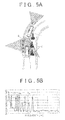
- FIGS. 4A and 4B are respectively a diagram showing the state where the rear millimeter wave radar is sensing a rear approaching vehicle that is approaching from behind, and a chart showing frequency peaks of a received wave;
- FIGS. 5A and 5B are respectively a diagram showing the state where the rear millimeter wave radar is sensing a rear approaching vehicle and a rear departing object that is moving away in the rear, and a chart showing frequency peaks of a received wave;
- FIG. 6 is a chart showing frequency peaks of a received wave due to a rear approaching object and a rear departing object
- FIGS. 7A , 7 B are a flowchart showing a method to detect a rear approaching object performed by the surroundings monitoring apparatus in accordance with this embodiment.
- FIG. 8 is a block diagram showing the configuration of a surroundings monitoring apparatus in accordance with a modification of this embodiment.
- FIG. 1 is a block diagram showing the configuration of a surroundings monitoring apparatus in accordance with this embodiment.
- the surroundings monitoring apparatus 1 includes an approaching object detection electronic control unit (ECU) 10 .
- the approaching object detection ECU 10 is connected with a front millimeter wave radar (front monitoring device) 20 , a steering sensor 30 , a navigation system 40 , a vehicle speed sensor 50 , and a rear millimeter wave radar (rear monitoring device) 60 in the input side, and a rear pre-crash safety (PCS) electronic control unit (ECU) 70 in the output side.
- a front millimeter wave radar front monitoring device
- a steering sensor 30 a navigation system 40
- vehicle speed sensor 50 a rear millimeter wave radar (rear monitoring device) 60
- rear millimeter wave radar rear monitoring device
- PCS rear pre-crash safety
- the front millimeter wave radar 20 is an FM-CW radar attached at the front of the vehicle to detect an object by emitting a millimeter wave forward and receiving a reflected wave from the object.
- the steering sensor 30 detects the steering angle according to a steering operation by the driver.
- the navigation system 40 provides road information including road geometry.
- the vehicle speed sensor 50 detects the vehicle speed by acquiring a vehicle wheel pulse.
- the rear millimeter wave radar 60 is an FM-CW radar attached at the rear of the vehicle to detect an object by emitting a millimeter wave rearward and receiving a reflected wave from the object.
- the rear PCS ECU 70 controls a pre-crash seatbelt (PSB) system, for example, and activates the PSB system, when the approaching object detection ECU 10 predicts a collision of a vehicle existing behind against the host vehicle, to tighten the seatbelt in preparation for the collision.
- PSB pre-crash seatbelt
- the approaching object detection ECU 10 has a front approaching object detection section (front approaching object detection means) 12 , an object specifying section (object specifying means) 14 , and a rear approaching object detection section (rear approaching object detection means) 16 .
- the front approaching object detection section 12 detects a front approaching object from among objects existing ahead of the vehicle based on information from the front millimeter wave radar 20 .
- the front approaching object means an object that is approaching the host vehicle from ahead, and includes an object moving closer to the host vehicle and a stationary object sensed by the front millimeter wave radar 20 while the host vehicle is running (such as a guardrail post and a traffic cone on the road, for example).
- the front approaching object does not include an object moving away, or a departing object, from the host vehicle as sensed by the front millimeter wave radar 20 while the host vehicle is running, such as a vehicle existing ahead that is accelerating.
- the front approaching object detection section 12 calculates the sensing angle, the distance from the host vehicle, the relative speed, and the relative acceleration of the front approaching object based on the information from the front millimeter wave radar 20 .
- the rear approaching object detection section 16 detects a rear approaching object from among objects existing behind the vehicle based on information from the rear millimeter wave radar 60 .
- the rear approaching object means an object that is approaching the host vehicle from behind, and includes an object moving closer to the host vehicle, such as a vehicle existing behind that is accelerating.
- the rear approaching object does not include an object moving away, or a departing object, from the host vehicle as sensed by the rear millimeter wave radar 60 while the host vehicle is running, whether moving or stationary.
- the object specifying section 14 specifies the object which has been sensed as a front approaching object by the front millimeter wave radar 20 from among the objects sensed by the rear millimeter wave radar 60 .
- the object specifying section 14 has a timing calculation section (timing calculation means) 14 a and a specifying section 14 b .
- the object specifying section 14 may further have an estimating section 14 c , as shown in FIG. 8 .
- the timing calculation section 14 a estimates the curvature radius R of a curve of the road ahead of the vehicle based on information from the steering sensor 30 and/or the navigation system 40 (this curvature radius R is referred to as “curve estimated R”). In addition, the timing calculation section 14 a may calculate the curvature radius R of a curve of the road ahead of the vehicle based on the reflected wave information on a roadside object existing ahead from the front millimeter wave radar 20 (this curvature radius R is referred to as “road geometry estimated R” for differentiation from the “curve estimated R”).
- the timing calculation section 14 a computes the timing for the front stationary object detected by the front approaching object detection section 12 to start being sensed by the rear millimeter wave radar 60 .
- the sensing angle ⁇ F , the distance D F , and the relative speed ( ⁇ V F ) of a front stationary object can be obtained by the front millimeter wave radar 20 .
- the curve estimated R can also be obtained by the steering sensor 30 and/or the car navigation system 40 .
- the viewing angle ⁇ R of the rear millimeter wave radar 60 is known.
- the apparent distance L of movement to be made by the front stationary object sensed by the front millimeter wave radar 20 before it starts being sensed by the rear millimeter wave radar 60 . Since the vehicle speed V of the host vehicle is available, the time T for the front stationary object, of the front approaching objects sensed by the front millimeter wave radar 20 , to start being sensed by the rear millimeter wave radar 60 can be calculated as L/V.
- the curve estimated R is infinite and the lane extends straight.
- the moving distance L can be calculated from the apparent track of movement to be made by the front approaching object before it is sensed by the rear millimeter wave radar 60 , utilizing the curve estimated R. Therefore, the time T for the front stationary object, of the front approaching objects sensed by the front millimeter wave radar 20 , to start being sensed by the rear millimeter wave radar 60 can be calculated as L/V t , where V t is the tangential component of the relative speed V. In this case, the relative speed of the front approaching object has been multiplied by ( ⁇ 1).
- the timing calculation section 14 a computes the timing for the front approaching moving object detected by the front approaching object detection section 12 to start being sensed by the rear millimeter wave radar 60 .
- the timing should be computed in consideration of the relative acceleration as well, unlike in the case of a stationary object.
- the road geometry estimated R is used in place of the curve estimated R to calculate the time T for a front stationary object and a front approaching moving object to start being sensed by the rear millimeter wave radar 60 in the same way as described above.
- the object specifying section 14 may have an estimating section 14 c ( FIG. 8 ) for estimating the distance D R , the angle ⁇ R , and the relative speed V R with respect to a front approaching object detected by the front approaching object detection section 12 at the timing for the object to start being sensed by the rear millimeter wave radar 60 .
- these values are estimated considering that the curve estimated R of the host vehicle has been multiplied by ( ⁇ 1) in the rear millimeter wave radar 60 .
- the specifying section 14 b specifies the object which has been sensed as a front approaching object by the front millimeter wave radar 20 from among the objects sensed by the rear millimeter wave radar 60 based on the information from the rear millimeter wave radar 60 and the timing information calculated by the timing calculation section 14 a .
- An object which has been sensed as a front approaching object moves rearward relative to, and then away from, the host vehicle as the host vehicle runs.
- a front approaching object is immediately excluded from candidates for a rear approaching object. This exclusion is described with reference to FIGS. 4 and 5 .
- frequency peaks P a during ascent and descent can be specified and paired with each other when a rear approaching vehicle comes in the sensing range S.
- the rear approaching vehicle can be detected easily.
- a stationary object such as a roadside object G and a cone C exists in the sensing range S of the rear millimeter wave radar 60 as shown in FIG. 5
- frequency peaks P a of a rear approaching vehicle are buried among a plurality of peaks P b of such a stationary object.
- the rear millimeter wave radar 60 is susceptible to the influence of reflection from a stationary object such as a roadside object.
- a stationary object such as a roadside object, rather than a rear approaching object to be detected, exists on the radar center axis, where the reception level of the radar is highest. Therefore, it is more likely that the peak detection may be delayed or that mispairing may occur.
- the surroundings monitoring apparatus 1 in accordance with this embodiment preliminarily calculates the timing for a front approaching object such as a front stationary object and a front approaching moving object to come into the sensing range S of the rear millimeter wave radar 60 since it inevitably will, and specifies the frequency peaks due to the front approaching object contained in the frequency peak information from the rear millimeter wave radar 60 , to exclude the object with the specified peaks from candidates from which a rear approaching object is to be detected.
- the frequency peaks P b that appear at the calculated timing while monitoring the frequency peaks from the rear millimeter wave radar 60 are specified as the peaks due to the front approaching object, as shown in FIG. 6 . Since a rear departing object sensed by the rear millimeter wave radar 60 (which has been sensed as a front approaching object) moves away from the host vehicle at the relative speed V R , the frequency peaks P b due to the rear departing object move to the right at a rate in accordance with the relative speed V R in the graph of FIG. 6 , and therefore can be tracked easily. The frequency peaks due to a rear approaching object move to the left in the graph of FIG. 6 .
- a rear departing object (which has been sensed as a front approaching object) can be specified more quickly and accurately.
- the rear approaching object detection section 16 excludes the object specified by the object specifying section 14 from the objects sensed by the rear millimeter wave radar 60 , or candidate for a rear approaching object, based on the information from the rear millimeter wave radar 60 and the information from the object specifying section 14 , to detect a rear approaching object.
- a rear approaching object is specified according to the sensing angle, the distance from the host vehicle, the relative speed, and the relative acceleration.
- the front millimeter wave radar 20 senses objects existing ahead of the vehicle, and the front approaching object detection section 12 detects a front approaching object that is approaching the host vehicle from ahead (step S 1 ). Then, it is determined whether or not a front approaching object has been detected (step S 2 ). If no front approaching object has been detected, the process is terminated. On the other hand, if a front approaching object has been detected, a front approaching object detection flag is set (step S 3 ), and then the process proceeds to step S 4 .
- step S 4 the timing calculation section 14 a calculates the sensing angle, the distance, the relative speed, and the relative acceleration of the front approaching object based on the information from the front millimeter wave radar 20 .
- the timing calculation section 14 a calculates the curve estimated R of the road ahead of the vehicle based on the information from the steering sensor 30 and/or the navigation system 40 .
- the timing calculation section 14 a calculates the road geometry estimated R of a curve of the road ahead of the vehicle based on the reflected wave information on a roadside object existing ahead from the front millimeter wave radar 20 .
- step S 5 it is determined whether or not the road geometry estimated R has been calculated. If it has been calculated, a road geometry estimated R calculation flag is set (step S 6 ), and then the process proceeds to step S 7 . On the other hand, if the road geometry estimated R has not been calculated, the process proceeds to step S 7 without setting the flag.
- step S 7 based on the curve estimated R, and the sensing angle, the distance, and the relative speed of a front stationary object sensed by the front millimeter wave radar 20 , the timing calculation section 14 a computes the timing for the front stationary object detected by the front approaching object detection section 12 to start being sensed by the rear millimeter wave radar 60 .
- the timing calculation section 14 a computes the timing for the front approaching moving object detected by the front approaching object detection section 12 to start being sensed by the rear millimeter wave radar 60 .
- the estimating section 14 c of the object specifying section 14 may estimate through computation the distance D R , the angle ⁇ R , and the relative speed V R at the timing for the front approaching object detected by the front approaching object detection section 12 to start being sensed by the rear millimeter wave radar 60 .
- step S 8 it is determined whether or not the road geometry estimated R calculation flag has been set for the road ahead (step S 8 ). If the flag has not been set, the process proceeds step S 9 .
- the object which has been sensed as a front approaching object is specified from among the objects sensed by the rear millimeter wave radar 60 at a tracking cycle (Q ⁇ , where 0 ⁇ 1.0), which is shorter than the normal target object detection cycle Q, to determine the target object.
- the target object may be specified based solely on the timing for the front approaching object to start being sensed by the rear millimeter wave radar 60 , or may be specified additionally based on the peak frequencies and the angle ⁇ R at the timing calculated from the distance D R and the relative speed V R .
- the frequency peaks P b due to the target object move to the right at a rate in accordance with the relative speed V R , and therefore can be tracked easily.
- step S 10 based on the road geometry estimated R, in place of the curve estimated R, and the sensing angle, the distance, and the relative speed of a front stationary object sensed by the front millimeter wave radar 20 , the timing calculation section 14 a computes the timing for the front stationary object detected by the front approaching object detection section 12 to start being sensed by the rear millimeter wave radar 60 , and performs a correction.
- the timing calculation section 14 a computes the timing for the front approaching moving object detected by the front approaching object detection section 12 to start being sensed by the rear millimeter wave radar 60 , and performs a correction. Then, the process proceeds to step S 11 .
- step S 11 the object which has been sensed as a front approaching object is specified from among the objects sensed by the rear millimeter wave radar 60 at a tracking cycle (Q ⁇ , where 0 ⁇ 1.0), which is further shorter than the cycle (Q ⁇ ) used in step S 9 , to determine the target object.
- the target object may be specified based solely on the corrected timing, or may be specified additionally based on the peak frequencies and the angle ⁇ R at the corrected timing calculated from the corrected distance D R and the corrected relative speed V R .
- the frequency peaks P b due to the target object move to the right at a rate in accordance with the relative speed V R , and therefore can be tracked easily.
- the rear approaching object detection section 16 After specifying the object which has been sensed as a front approaching object from among the objects sensed by the rear millimeter wave radar 60 , in step S 12 , the rear approaching object detection section 16 detects a rear approaching object that is approaching the host vehicle from behind. At this time, since the object which has been sensed as a front approaching object such as a roadside object has been specified by the specifying section 14 b , the specified object is excluded from the objects sensed by the rear millimeter wave radar 60 , or candidate for a rear approaching object, to detect a rear approaching object. When a collision of a vehicle existing behind against the host vehicle is predicted, a signal is sent to the rear PCS ECU 70 to activate the PSB system to tighten the seatbelt in preparation for the collision.
- the surroundings monitoring apparatus 1 in accordance with this embodiment can link the information from the front millimeter wave radar 20 and the information from the rear millimeter wave radar 60 to preliminarily exclude the object which has been detected as a front approaching object by the front approaching object detection section 12 from among candidates for a rear approaching object before detecting a rear approaching object from among the objects sensed by the rear millimeter wave radar 60 .
- the timing calculation section 14 a can calculate the timing for a front approaching object sensed by the front millimeter wave radar 20 to start being detected by the rear millimeter wave radar 60 , and the specifying section 14 b can easily specify the object which starts being sensed by the rear millimeter wave radar 60 at the calculated timing as an object to be excluded from candidates for a rear approaching object. That is, by monitoring frequency peaks of a reflected wave received by the rear millimeter wave radar 60 , it is possible to easily specify an object corresponding to the peaks that appear at the calculated timing as the front approaching object which has been sensed by the front millimeter wave radar 20 , and to exclude the specified object from candidates for a rear approaching object.
- the road geometry estimated R is utilized to calculate the timing for a rear departing object (which has been sensed as a front approaching object) to start being sensed by the rear millimeter wave radar 60 , to correct the timing calculated based on the road geometry estimated R. Then, a rear departing object can be specified based on the corrected timing to be excluded from candidates for a rear approaching object.
- the timing for a rear departing object to start being detected can be calculated utilizing a more accurate curvature radius R, in other words, utilizing the road geometry estimated R obtained by the front millimeter wave radar 20 , which is more accurate than the curve estimated R based on the steering angle of the steering wheel having a play and the curve estimated R based on the information from the navigation system 40 .
- R curvature radius
- the timing for a rear departing object to start being detected, and the distance, the angle and the relative speed at that timing can be estimated utilizing the curve estimated R based on the host vehicle information such as the steering angle of the steering wheel and the curve estimated R based on the information from the navigation system 40 , such estimated values are no more than predictions.
- the road geometry estimated R which is more accurate, it is possible to improve the reliability of and sufficiently shorten the cycle to determine the target object.
- a stationary object and an approaching moving object temporarily existing on the road cannot be recognized with only the navigation information and the host vehicle information.
- the rear millimeter wave radar 60 can detect a rear departing object with greatly improved precision compared to the case where only the navigation information, for example, is utilized.
- a rear departing object can be specified as the target object immediately and accurately to be excluded from candidates for a rear approaching object, it is possible to avoid mispairing of peaks of a reflected wave due to the rear approaching object, and to shorten the cycle to determine the target object.
- the present invention is not limited to the above embodiment, and may be modified in various ways.
- the rear PCS ECU 70 is connected to the output side of the approaching object detection ECU 10 in the above embodiment
- ECUs of various systems may be connected thereto, such as systems for ACC (adaptive cruise control), stop and go control for use in traffic jams, obstruction warning, and intervening brake control, to utilize information on a rear approaching object in these systems.
- ACC adaptive cruise control
- stop and go control for use in traffic jams
- obstruction warning obstruction warning
- intervening brake control to utilize information on a rear approaching object in these systems.
Abstract
Description
DR∝(Wup+Wdw)/2 (1)
VR∝(Wdw−Wup)/2 (2)
Claims (6)
Applications Claiming Priority (3)
| Application Number | Priority Date | Filing Date | Title |
|---|---|---|---|
| JP2007001585A JP4518080B2 (en) | 2007-01-09 | 2007-01-09 | Perimeter monitoring device |
| JP2007-001585 | 2007-01-09 | ||
| PCT/IB2008/000752 WO2008084408A2 (en) | 2007-01-09 | 2008-01-03 | Surroundings monitoring apparatus for a motor vehicle |
Publications (2)
| Publication Number | Publication Date |
|---|---|
| US20100141413A1 US20100141413A1 (en) | 2010-06-10 |
| US8094000B2 true US8094000B2 (en) | 2012-01-10 |
Family
ID=39535328
Family Applications (1)
| Application Number | Title | Priority Date | Filing Date |
|---|---|---|---|
| US12/448,051 Active 2029-02-10 US8094000B2 (en) | 2007-01-09 | 2008-01-03 | Surroundings monitoring apparatus for a motor vehicle |
Country Status (5)
| Country | Link |
|---|---|
| US (1) | US8094000B2 (en) |
| EP (1) | EP2100164B1 (en) |
| JP (1) | JP4518080B2 (en) |
| CN (1) | CN101578533B (en) |
| WO (1) | WO2008084408A2 (en) |
Cited By (1)
| Publication number | Priority date | Publication date | Assignee | Title |
|---|---|---|---|---|
| US20150287324A1 (en) * | 2014-04-02 | 2015-10-08 | Robert Bosch Gmbh | Driver assistance system including warning sensing by vehicle sensor mounted on opposite vehicle side |
Families Citing this family (7)
| Publication number | Priority date | Publication date | Assignee | Title |
|---|---|---|---|---|
| GB2491560B (en) | 2011-05-12 | 2014-12-03 | Jaguar Land Rover Ltd | Monitoring apparatus and method |
| EP2808217B1 (en) * | 2013-05-27 | 2019-02-27 | Volvo Car Corporation | Vehicle safety arrangement and method |
| JP6413240B2 (en) * | 2014-01-08 | 2018-10-31 | 株式会社デンソー | Vehicle control device and vehicle |
| JP6408860B2 (en) * | 2014-10-22 | 2018-10-17 | 株式会社デンソー | Object detection device |
| JP6292097B2 (en) * | 2014-10-22 | 2018-03-14 | 株式会社デンソー | Lateral ranging sensor diagnostic device |
| US9868443B2 (en) * | 2015-04-27 | 2018-01-16 | GM Global Technology Operations LLC | Reactive path planning for autonomous driving |
| JP6589840B2 (en) | 2016-12-07 | 2019-10-16 | トヨタ自動車株式会社 | Driving assistance device |
Citations (13)
| Publication number | Priority date | Publication date | Assignee | Title |
|---|---|---|---|---|
| JPH03282707A (en) | 1990-03-30 | 1991-12-12 | Mazda Motor Corp | Environment recognition device for mobile vehicle |
| EP0936471A2 (en) | 1998-02-14 | 1999-08-18 | DaimlerChrysler AG | Vehicle with object detecting device |
| US20020067287A1 (en) | 2000-08-16 | 2002-06-06 | Delcheccolo Michael Joseph | Near object detection system |
| JP2003185744A (en) | 2001-12-14 | 2003-07-03 | Fujitsu Ten Ltd | Radar system |
| JP2004359086A (en) | 2003-06-04 | 2004-12-24 | Mitsubishi Electric Corp | Back/side direction alarm device |
| JP2005032063A (en) | 2003-07-08 | 2005-02-03 | Nissan Motor Co Ltd | On-vehicle obstacle detector |
| US6900754B2 (en) * | 2001-03-15 | 2005-05-31 | Fujitsu Tem Limited | Signal processing method for use with scanning radar |
| JP2005182198A (en) | 2003-12-16 | 2005-07-07 | Fujitsu Ten Ltd | Rear-end collision prevention device |
| JP2005271756A (en) | 2004-03-25 | 2005-10-06 | Toyota Motor Corp | Alarm device for vehicle |
| WO2005103757A1 (en) | 2004-04-22 | 2005-11-03 | Siemens Aktiengesellschaft | Blindspot sensor system |
| US20050248445A1 (en) | 2004-05-06 | 2005-11-10 | Mitsubishi Denki Kabushiki Kaisha | Alarm device for vehicle |
| JP2006088896A (en) | 2004-09-24 | 2006-04-06 | Mitsubishi Electric Corp | Rear side part warning device for vehicle |
| WO2006045649A1 (en) | 2004-10-29 | 2006-05-04 | Robert Bosch Gmbh | Fmcw radar featuring suppression of stationary targets |
Family Cites Families (4)
| Publication number | Priority date | Publication date | Assignee | Title |
|---|---|---|---|---|
| CN1057234A (en) * | 1990-06-11 | 1991-12-25 | 邢伟华 | Automobile collision avoidance radar |
| CN1198388A (en) * | 1997-05-05 | 1998-11-11 | 黑龙江省铁力市弘亚实业有限公司 | Colliding-proof radar for car |
| CN1224541C (en) * | 2003-03-20 | 2005-10-26 | 上海交通大学 | Active device for preventing automobile wear end collision |
| CN1274536C (en) * | 2003-07-15 | 2006-09-13 | 范子林 | Intelligent control system for motor vehicle safety running |
-
2007
- 2007-01-09 JP JP2007001585A patent/JP4518080B2/en active Active
-
2008
- 2008-01-03 US US12/448,051 patent/US8094000B2/en active Active
- 2008-01-03 WO PCT/IB2008/000752 patent/WO2008084408A2/en active Application Filing
- 2008-01-03 EP EP08719389.2A patent/EP2100164B1/en not_active Not-in-force
- 2008-01-03 CN CN200880001596XA patent/CN101578533B/en not_active Expired - Fee Related
Patent Citations (18)
| Publication number | Priority date | Publication date | Assignee | Title |
|---|---|---|---|---|
| JPH03282707A (en) | 1990-03-30 | 1991-12-12 | Mazda Motor Corp | Environment recognition device for mobile vehicle |
| EP0936471A2 (en) | 1998-02-14 | 1999-08-18 | DaimlerChrysler AG | Vehicle with object detecting device |
| US6265968B1 (en) | 1998-02-14 | 2001-07-24 | Daimlerchrysler Ag | Vehicle with object detection device |
| US20020067287A1 (en) | 2000-08-16 | 2002-06-06 | Delcheccolo Michael Joseph | Near object detection system |
| US6784828B2 (en) * | 2000-08-16 | 2004-08-31 | Raytheon Company | Near object detection system |
| US6900754B2 (en) * | 2001-03-15 | 2005-05-31 | Fujitsu Tem Limited | Signal processing method for use with scanning radar |
| JP2003185744A (en) | 2001-12-14 | 2003-07-03 | Fujitsu Ten Ltd | Radar system |
| JP2004359086A (en) | 2003-06-04 | 2004-12-24 | Mitsubishi Electric Corp | Back/side direction alarm device |
| JP2005032063A (en) | 2003-07-08 | 2005-02-03 | Nissan Motor Co Ltd | On-vehicle obstacle detector |
| JP2005182198A (en) | 2003-12-16 | 2005-07-07 | Fujitsu Ten Ltd | Rear-end collision prevention device |
| JP2005271756A (en) | 2004-03-25 | 2005-10-06 | Toyota Motor Corp | Alarm device for vehicle |
| WO2005103757A1 (en) | 2004-04-22 | 2005-11-03 | Siemens Aktiengesellschaft | Blindspot sensor system |
| US20070179712A1 (en) | 2004-04-22 | 2007-08-02 | Martin Brandt | Blind spot sensor system |
| JP2007533991A (en) | 2004-04-22 | 2007-11-22 | シーメンス アクチエンゲゼルシヤフト | Blind spot sensor system |
| US7504986B2 (en) | 2004-04-22 | 2009-03-17 | Continental Automotive Gmbh | Blind spot sensor system |
| US20050248445A1 (en) | 2004-05-06 | 2005-11-10 | Mitsubishi Denki Kabushiki Kaisha | Alarm device for vehicle |
| JP2006088896A (en) | 2004-09-24 | 2006-04-06 | Mitsubishi Electric Corp | Rear side part warning device for vehicle |
| WO2006045649A1 (en) | 2004-10-29 | 2006-05-04 | Robert Bosch Gmbh | Fmcw radar featuring suppression of stationary targets |
Non-Patent Citations (1)
| Title |
|---|
| Sep. 1, 2009 Office Action issued in Japanese Patent Application No. 2007-001585 (with translation). |
Cited By (2)
| Publication number | Priority date | Publication date | Assignee | Title |
|---|---|---|---|---|
| US20150287324A1 (en) * | 2014-04-02 | 2015-10-08 | Robert Bosch Gmbh | Driver assistance system including warning sensing by vehicle sensor mounted on opposite vehicle side |
| US9552732B2 (en) * | 2014-04-02 | 2017-01-24 | Robert Bosch Gmbh | Driver assistance system including warning sensing by vehicle sensor mounted on opposite vehicle side |
Also Published As
| Publication number | Publication date |
|---|---|
| US20100141413A1 (en) | 2010-06-10 |
| JP2008171082A (en) | 2008-07-24 |
| WO2008084408A2 (en) | 2008-07-17 |
| JP4518080B2 (en) | 2010-08-04 |
| WO2008084408A3 (en) | 2008-09-04 |
| EP2100164B1 (en) | 2014-10-15 |
| CN101578533A (en) | 2009-11-11 |
| CN101578533B (en) | 2012-07-04 |
| EP2100164A2 (en) | 2009-09-16 |
Similar Documents
| Publication | Publication Date | Title |
|---|---|---|
| US8094000B2 (en) | Surroundings monitoring apparatus for a motor vehicle | |
| US9753130B2 (en) | Target detection apparatus | |
| US8200419B2 (en) | Braking control system and braking control method | |
| US9102329B2 (en) | Tracking control apparatus | |
| US6661370B2 (en) | Radar data processing apparatus and data processing method | |
| US20140297170A1 (en) | Driving support system | |
| JP4992367B2 (en) | Object detection apparatus, object detection method, and program executed by computer | |
| US9372262B2 (en) | Device and method for judging likelihood of collision between vehicle and target, vehicle collision avoidance system, and method for avoiding collision between vehicle and target | |
| JP2007531872A (en) | Automotive radar system | |
| US11136013B2 (en) | Vehicle control apparatus and vehicle control method | |
| US10787170B2 (en) | Vehicle control method and apparatus | |
| US10569730B2 (en) | Object detecting apparatus and object detecting method | |
| EP3539837B1 (en) | A vehicle radar system for detecting preceding vehicles | |
| JP2008026095A (en) | On-vehicle radar control method and on-vehicle radar control device | |
| JP2012089114A (en) | Obstacle recognition device | |
| US20190061748A1 (en) | Collision prediction apparatus | |
| JP2013137710A (en) | Obstacle detector | |
| US20220348209A1 (en) | Vehicle system for detection of oncoming vehicles | |
| KR20050014727A (en) | Method and apparatus for recognizing predetermined particular part of vehicle | |
| US6819261B2 (en) | Reliable obstacle detecting driving support apparatus | |
| JP2002175599A (en) | Lane position estimating device for precedent vehicle or target | |
| JP2006048568A (en) | Object recognition method and object recognizing device | |
| US11435474B2 (en) | Vehicle system for detection of oncoming vehicles | |
| KR20210101877A (en) | Apparatus and method for blind-spot collision warning of vehicle | |
| JP5777752B2 (en) | Inter-vehicle distance measuring device |
Legal Events
| Date | Code | Title | Description |
|---|---|---|---|
| AS | Assignment |
Owner name: TOYOTA JIDOSHA KABUSHIKI KAISHA,JAPAN Free format text: ASSIGNMENT OF ASSIGNORS INTEREST;ASSIGNOR:SUZUKI, KOJI;REEL/FRAME:022811/0330 Effective date: 20090521 Owner name: TOYOTA JIDOSHA KABUSHIKI KAISHA, JAPAN Free format text: ASSIGNMENT OF ASSIGNORS INTEREST;ASSIGNOR:SUZUKI, KOJI;REEL/FRAME:022811/0330 Effective date: 20090521 |
|
| FEPP | Fee payment procedure |
Free format text: PAYOR NUMBER ASSIGNED (ORIGINAL EVENT CODE: ASPN); ENTITY STATUS OF PATENT OWNER: LARGE ENTITY |
|
| STCF | Information on status: patent grant |
Free format text: PATENTED CASE |
|
| FPAY | Fee payment |
Year of fee payment: 4 |
|
| MAFP | Maintenance fee payment |
Free format text: PAYMENT OF MAINTENANCE FEE, 8TH YEAR, LARGE ENTITY (ORIGINAL EVENT CODE: M1552); ENTITY STATUS OF PATENT OWNER: LARGE ENTITY Year of fee payment: 8 |
|
| MAFP | Maintenance fee payment |
Free format text: PAYMENT OF MAINTENANCE FEE, 12TH YEAR, LARGE ENTITY (ORIGINAL EVENT CODE: M1553); ENTITY STATUS OF PATENT OWNER: LARGE ENTITY Year of fee payment: 12 |