US8152819B2 - Catheter support for stent delivery - Google Patents
Catheter support for stent delivery Download PDFInfo
- Publication number
- US8152819B2 US8152819B2 US12/829,135 US82913510A US8152819B2 US 8152819 B2 US8152819 B2 US 8152819B2 US 82913510 A US82913510 A US 82913510A US 8152819 B2 US8152819 B2 US 8152819B2
- Authority
- US
- United States
- Prior art keywords
- stent
- mounting body
- catheter
- balloon
- delivery catheter
- Prior art date
- Legal status (The legal status is an assumption and is not a legal conclusion. Google has not performed a legal analysis and makes no representation as to the accuracy of the status listed.)
- Expired - Fee Related
Links
Images


Classifications
-
- A—HUMAN NECESSITIES
- A61—MEDICAL OR VETERINARY SCIENCE; HYGIENE
- A61M—DEVICES FOR INTRODUCING MEDIA INTO, OR ONTO, THE BODY; DEVICES FOR TRANSDUCING BODY MEDIA OR FOR TAKING MEDIA FROM THE BODY; DEVICES FOR PRODUCING OR ENDING SLEEP OR STUPOR
- A61M25/00—Catheters; Hollow probes
- A61M25/10—Balloon catheters
- A61M25/104—Balloon catheters used for angioplasty
-
- A—HUMAN NECESSITIES
- A61—MEDICAL OR VETERINARY SCIENCE; HYGIENE
- A61F—FILTERS IMPLANTABLE INTO BLOOD VESSELS; PROSTHESES; DEVICES PROVIDING PATENCY TO, OR PREVENTING COLLAPSING OF, TUBULAR STRUCTURES OF THE BODY, e.g. STENTS; ORTHOPAEDIC, NURSING OR CONTRACEPTIVE DEVICES; FOMENTATION; TREATMENT OR PROTECTION OF EYES OR EARS; BANDAGES, DRESSINGS OR ABSORBENT PADS; FIRST-AID KITS
- A61F2/00—Filters implantable into blood vessels; Prostheses, i.e. artificial substitutes or replacements for parts of the body; Appliances for connecting them with the body; Devices providing patency to, or preventing collapsing of, tubular structures of the body, e.g. stents
- A61F2/95—Instruments specially adapted for placement or removal of stents or stent-grafts
- A61F2/958—Inflatable balloons for placing stents or stent-grafts
-
- A—HUMAN NECESSITIES
- A61—MEDICAL OR VETERINARY SCIENCE; HYGIENE
- A61L—METHODS OR APPARATUS FOR STERILISING MATERIALS OR OBJECTS IN GENERAL; DISINFECTION, STERILISATION OR DEODORISATION OF AIR; CHEMICAL ASPECTS OF BANDAGES, DRESSINGS, ABSORBENT PADS OR SURGICAL ARTICLES; MATERIALS FOR BANDAGES, DRESSINGS, ABSORBENT PADS OR SURGICAL ARTICLES
- A61L29/00—Materials for catheters, medical tubing, cannulae, or endoscopes or for coating catheters
- A61L29/04—Macromolecular materials
-
- A—HUMAN NECESSITIES
- A61—MEDICAL OR VETERINARY SCIENCE; HYGIENE
- A61M—DEVICES FOR INTRODUCING MEDIA INTO, OR ONTO, THE BODY; DEVICES FOR TRANSDUCING BODY MEDIA OR FOR TAKING MEDIA FROM THE BODY; DEVICES FOR PRODUCING OR ENDING SLEEP OR STUPOR
- A61M25/00—Catheters; Hollow probes
- A61M25/10—Balloon catheters
- A61M25/1011—Multiple balloon catheters
-
- A—HUMAN NECESSITIES
- A61—MEDICAL OR VETERINARY SCIENCE; HYGIENE
- A61M—DEVICES FOR INTRODUCING MEDIA INTO, OR ONTO, THE BODY; DEVICES FOR TRANSDUCING BODY MEDIA OR FOR TAKING MEDIA FROM THE BODY; DEVICES FOR PRODUCING OR ENDING SLEEP OR STUPOR
- A61M25/00—Catheters; Hollow probes
- A61M25/10—Balloon catheters
- A61M25/1018—Balloon inflating or inflation-control devices
- A61M25/10184—Means for controlling or monitoring inflation or deflation
-
- A—HUMAN NECESSITIES
- A61—MEDICAL OR VETERINARY SCIENCE; HYGIENE
- A61F—FILTERS IMPLANTABLE INTO BLOOD VESSELS; PROSTHESES; DEVICES PROVIDING PATENCY TO, OR PREVENTING COLLAPSING OF, TUBULAR STRUCTURES OF THE BODY, e.g. STENTS; ORTHOPAEDIC, NURSING OR CONTRACEPTIVE DEVICES; FOMENTATION; TREATMENT OR PROTECTION OF EYES OR EARS; BANDAGES, DRESSINGS OR ABSORBENT PADS; FIRST-AID KITS
- A61F2/00—Filters implantable into blood vessels; Prostheses, i.e. artificial substitutes or replacements for parts of the body; Appliances for connecting them with the body; Devices providing patency to, or preventing collapsing of, tubular structures of the body, e.g. stents
- A61F2/95—Instruments specially adapted for placement or removal of stents or stent-grafts
- A61F2/9522—Means for mounting a stent or stent-graft onto or into a placement instrument
-
- A—HUMAN NECESSITIES
- A61—MEDICAL OR VETERINARY SCIENCE; HYGIENE
- A61F—FILTERS IMPLANTABLE INTO BLOOD VESSELS; PROSTHESES; DEVICES PROVIDING PATENCY TO, OR PREVENTING COLLAPSING OF, TUBULAR STRUCTURES OF THE BODY, e.g. STENTS; ORTHOPAEDIC, NURSING OR CONTRACEPTIVE DEVICES; FOMENTATION; TREATMENT OR PROTECTION OF EYES OR EARS; BANDAGES, DRESSINGS OR ABSORBENT PADS; FIRST-AID KITS
- A61F2/00—Filters implantable into blood vessels; Prostheses, i.e. artificial substitutes or replacements for parts of the body; Appliances for connecting them with the body; Devices providing patency to, or preventing collapsing of, tubular structures of the body, e.g. stents
- A61F2/95—Instruments specially adapted for placement or removal of stents or stent-grafts
- A61F2/958—Inflatable balloons for placing stents or stent-grafts
- A61F2002/9583—Means for holding the stent on the balloon, e.g. using protrusions, adhesives or an outer sleeve
- A61F2002/9586—Means for holding the stent on the balloon, e.g. using protrusions, adhesives or an outer sleeve the means being inside the balloon
-
- A—HUMAN NECESSITIES
- A61—MEDICAL OR VETERINARY SCIENCE; HYGIENE
- A61M—DEVICES FOR INTRODUCING MEDIA INTO, OR ONTO, THE BODY; DEVICES FOR TRANSDUCING BODY MEDIA OR FOR TAKING MEDIA FROM THE BODY; DEVICES FOR PRODUCING OR ENDING SLEEP OR STUPOR
- A61M25/00—Catheters; Hollow probes
- A61M25/10—Balloon catheters
- A61M25/1011—Multiple balloon catheters
- A61M2025/1013—Multiple balloon catheters with concentrically mounted balloons, e.g. being independently inflatable
-
- A—HUMAN NECESSITIES
- A61—MEDICAL OR VETERINARY SCIENCE; HYGIENE
- A61M—DEVICES FOR INTRODUCING MEDIA INTO, OR ONTO, THE BODY; DEVICES FOR TRANSDUCING BODY MEDIA OR FOR TAKING MEDIA FROM THE BODY; DEVICES FOR PRODUCING OR ENDING SLEEP OR STUPOR
- A61M25/00—Catheters; Hollow probes
- A61M25/10—Balloon catheters
- A61M2025/1043—Balloon catheters with special features or adapted for special applications
- A61M2025/1063—Balloon catheters with special features or adapted for special applications having only one lumen used for guide wire and inflation, e.g. to minimise the diameter
-
- A—HUMAN NECESSITIES
- A61—MEDICAL OR VETERINARY SCIENCE; HYGIENE
- A61M—DEVICES FOR INTRODUCING MEDIA INTO, OR ONTO, THE BODY; DEVICES FOR TRANSDUCING BODY MEDIA OR FOR TAKING MEDIA FROM THE BODY; DEVICES FOR PRODUCING OR ENDING SLEEP OR STUPOR
- A61M25/00—Catheters; Hollow probes
- A61M25/10—Balloon catheters
- A61M2025/1043—Balloon catheters with special features or adapted for special applications
- A61M2025/1079—Balloon catheters with special features or adapted for special applications having radio-opaque markers in the region of the balloon
-
- A—HUMAN NECESSITIES
- A61—MEDICAL OR VETERINARY SCIENCE; HYGIENE
- A61M—DEVICES FOR INTRODUCING MEDIA INTO, OR ONTO, THE BODY; DEVICES FOR TRANSDUCING BODY MEDIA OR FOR TAKING MEDIA FROM THE BODY; DEVICES FOR PRODUCING OR ENDING SLEEP OR STUPOR
- A61M25/00—Catheters; Hollow probes
- A61M25/10—Balloon catheters
- A61M2025/1043—Balloon catheters with special features or adapted for special applications
- A61M2025/1081—Balloon catheters with special features or adapted for special applications having sheaths or the like for covering the balloon but not forming a permanent part of the balloon, e.g. retractable, dissolvable or tearable sheaths
-
- A—HUMAN NECESSITIES
- A61—MEDICAL OR VETERINARY SCIENCE; HYGIENE
- A61M—DEVICES FOR INTRODUCING MEDIA INTO, OR ONTO, THE BODY; DEVICES FOR TRANSDUCING BODY MEDIA OR FOR TAKING MEDIA FROM THE BODY; DEVICES FOR PRODUCING OR ENDING SLEEP OR STUPOR
- A61M25/00—Catheters; Hollow probes
- A61M25/10—Balloon catheters
- A61M2025/1043—Balloon catheters with special features or adapted for special applications
- A61M2025/1093—Balloon catheters with special features or adapted for special applications having particular tip characteristics
-
- A—HUMAN NECESSITIES
- A61—MEDICAL OR VETERINARY SCIENCE; HYGIENE
- A61M—DEVICES FOR INTRODUCING MEDIA INTO, OR ONTO, THE BODY; DEVICES FOR TRANSDUCING BODY MEDIA OR FOR TAKING MEDIA FROM THE BODY; DEVICES FOR PRODUCING OR ENDING SLEEP OR STUPOR
- A61M25/00—Catheters; Hollow probes
- A61M25/10—Balloon catheters
- A61M25/1018—Balloon inflating or inflation-control devices
- A61M25/10184—Means for controlling or monitoring inflation or deflation
- A61M25/10185—Valves
- A61M25/10186—One-way valves
Definitions
- a guiding catheter is percutaneously introduced into the cardiovascular system of a patient through a vessel and advanced through therein until the distal end thereof is at a desired location in the vasculature.
- a guidewire and a dilatation catheter having a balloon on the distal end thereof are introduced through the guiding catheter with the guidewire sliding through the dilatation catheter.
- the guidewire is first advanced out of the guiding catheter into the patient's coronary vasculature and the dilatation catheter is advanced over the previously advanced guidewire until the dilatation balloon is properly positioned across the lesion.
- the flexible, expandable, preformed balloon is inflated to a predetermined size with a liquid or gas at relatively high pressures, such as greater than about four atmospheres, to radially compress the arthrosclerotic plaque of the lesion against the inside of the artery wall and thereby dilate the lumen of the artery.
- the balloon is then deflated to a small profile so that the dilatation catheter may be withdrawn from the patients vasculature and blood flow resumed through the dilated artery.
- a physician can implant an intravascular prosthesis, called a stent, for maintaining vascular patency inside the artery at the lesion.
- the stent is expanded to a larger diameter for placement or implantation in the vasculature, often by the balloon portion of the catheter.
- Stents delivered to a restricted coronary artery, expanded to a larger diameter as by a balloon catheter, and left in place in the artery at the site of a dilated lesion are shown in U.S. Pat. No.
- the present invention is particularly directed to improved arrangements for catheters of reduced profile for performing angioplasty and for releasably attaching the stent to the catheter to facilitate delivery thereof.
- the invention is applicable to all the various types of catheters used in such procedures, including rapid exchange types and over-the-wire types.
- stents are prosthetic devices which can be positioned within a body cavity, for example, a blood vessel or in some other difficulty accessible place of the body of a living human or animal.
- the stent prosthesis is formed of a generally tubular body, the diameter of which can be decreased or increased.
- Stents are particularly useful for permanently widening a vessel which is either in a narrowed state, or internally supporting a vessel damaged by an aneurysm. Such stents are typically introduced into the body cavity by use of a catheter.
- the catheter is usually of the balloon catheter type in which the balloon is utilized to expand the stent, which is positioned over the balloon for delivery, to place it in a selected location in the body cavity.
- the present invention is particularly directed to improved arrangements for releasably attaching the stent to the catheter to facilitate delivery thereof.
- the stent is held in place on the catheter by means of an enlarged mounting body carried within the balloon by the catheter shaft to which the stent and balloon are fitted.
- the stent is fitted over the balloon, as by crimping.
- the enlarged body is axially movable on the inner shaft of the catheter so that it can be retracted from the stent mounting area to provide a small profile for performing angioplasty.
- the catheter can then be withdrawn; the enlarged body can be moved into the stent mounting area; the stent can be mounted and the catheter can be re-inserted to implant the stent.
- the enlarged body can be arranged to be reducible and enlargeable in size rather than being movable.
- the movable mounting body may be carried outside the balloon.
- a catheter of this type makes possible a method in which, before stent loading with the associated mounting body arranged to provide reduced diameter in the balloon region, the catheter may be used to dilate a lesion or the like.
- the catheter may be withdrawn and the mounting body may then be selectively manipulated to provide an enlarged diameter in the stent mounting region and a stent may be loaded onto the catheter.
- the catheter may be re-inserted to implant the stent.
- the catheter may be withdrawn or left in situ and the mounting body may be manipulated to provide reduced diameter again and the catheter may be used for any post-dilation desired.
- the catheter may be used multiple times in the procedure for dilation and stent implantation.
- FIG. 1 is an isometric view, a portion of which is enlarged and in longitudinal section, of a balloon catheter having a mounting body in a retracted position;
- FIG. 2 is an even more enlarged view in longitudinal cross-section of the distal end portion of the catheter of FIG. 1 ;
- FIG. 3 is similar to FIG. 2 but showing the mounting body advanced to receive a stent mounted on the balloon;
- FIG. 4 is an enlarged cross-sectional view of the distal end portion of the catheter of FIG. 1 similar to that of enlarged view FIG. 3 but showing the balloon in an expanded condition along with the expanded stent;
- FIG. 5 is a schematic showing of a preferred mounting body carried by the catheter shaft within the balloon, the body being spirally cut to improve flexibility;
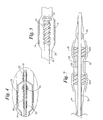
- FIG. 6 is a schematic showing in cross-section of another embodiment of the invention with a mounting body positioned to receive a stent but with a stent not yet mounted;
- FIG. 7 is a schematic showing of another embodiment of the invention.
- FIG. 8 is a schematic showing of a means for conveniently crimping the stent on the embodiment shown in FIG. 5 ;
- FIG. 9 is a schematic showing of yet another embodiment of the invention.
- FIG. 10 is a showing of another embodiment of a mounting body according to the invention.
- FIG. 11 is a schematic of an enlargeable mounting body which is not axially movable
- FIG. 12 is a schematic of an alternate enlargeable mounting arrangement which is not axially movable
- FIGS. 13 and 14 are schematic showings of yet another embodiment in which the axially movable mounting body is carried outside the balloon;
- FIGS. 15 and 16 are schematic showings of still yet another embodiment of the invention.
- FIGS. 17 and 18 are a modified version of the embodiment shown in FIG. 11 ;
- FIGS. 19 and 20 are modified versions of the embodiment shown in FIG. 11 ;
- FIG. 21 shows a version of the embodiment shown in FIG. 11 in which a syringe is inserted into the distal end of the liner of the catheter.
- an angioplasty and stent delivery catheter system generally indicated at 10 includes a balloon catheter 12 having a balloon 14 on a distal end portion generally indicated at 16 .
- FIG. 1 shows a proximal portion of the catheter at 12 a and a distal portion 12 b in enlarged view.
- FIGS. 2 and 3 show the distal end portion 16 in an even more enlarged view.
- the illustrative catheter 12 is of the type known as a rapid exchange or single operator catheter. However, other types of catheters may be used, such as over the wire and fixed wire types.
- the balloon 14 is fixed to the catheter 12 by standard means. The balloon is shown in its contracted state in FIGS. 1-3 . In FIGS. 1 and 2 the catheter is shown prepared for performing angioplasty and in FIG. 3 it is prepared for stent implantation.
- an axially movable mounting body 30 is shown in a position proximal to the end portion 16 of the catheter where a stent may be mounted.
- the catheter includes at its proximal end a manifold, generally designated 13 , as is known in the art.
- the manifold includes an inflation port 15 as is known in the art.
- a wire 31 is attached to body 30 to enable remote (from the proximal catheter end) advancement and retraction of it axially on inner lumen 26 over which it slides.
- the catheter In the retracted position shown in FIGS. 1 and 2 , the catheter has a low profile for performing angioplasty. This position is a retracted position and is selected by operation of a pull wire 31 .
- the retracted position of the mounting body may vary. To maximize the low profile of the distal end 16 of the catheter, the retracted position may be within the outer member 24 .
- the balloon is deflated, the catheter is withdrawn and the mounting body is advanced by means of wire 31 to the stent mounting position shown in FIG. 3 .
- a stent 18 may then be fixed about the deflated balloon by crimping it thereto.
- the enlarged mounting body may be, as in this instance, substantially the same length as the stent.
- the stent has a larger expanded diameter which is obtained when the balloon is again expanded in the known manner. That is, the stent is released from the catheter upon expansion of the balloon as shown in FIG. 4 to be placed in a vessel at the desired location.
- removal of the balloon and catheter may be accomplished, leaving the stent in place.
- Exemplary dimensions for the inner 26 are a diameter of 1 ⁇ 2 mm and for body 30 a diameter of 3 ⁇ 4 mm.
- the balloon is either bonded at its ends by adhesive 20 and 22 , respectively to the outer member 24 of the catheter and to the inner member 26 of the catheter in the manner as shown, or is made one-piece with the outer member as is known in the art.
- the catheter balloon may be inflated by fluid (gas or liquid) from an inflation port extending from a lumen 28 (seen in FIGS. 2 and 3 ) contained in the catheter shaft and opening into the balloon as shown, or by other known arrangements, depending on the design of the catheter.
- fluid gas or liquid
- the details and mechanics of balloon inflation and specific overall catheter construction will vary according to the particular design involved in any given instance, and are known in the art per se. Such details are only shown schematically herein. All variations are acceptable for use with this invention.
- Any balloon expandable stent may be used with this invention.
- Many are known in the art including plastic and metal stents. Some are more well known such as the stainless steel stent shown in U.S. Pat. No. 4,735,665; the wire stent shown in U.S. Pat. No. 4,950,227; another metal stent shown in European Patent Application EP0 707 837 A1 and that shown in U.S. Pat. No. 5,445,646, or U.S. Pat. No. 5,242,451. All of these patents are incorporated herein by reference. Also, shape memory metal stents may be used. As already indicated the stent of PCT Application 960 3092 A1 is particularly preferred.
- the stent is typically for example about 16 mm long, while the balloon may be 20 mm long for example. These dimensions, however, are merely representative for illustrative purposes only and are not meant to be limiting.
- the stent is positioned over the balloon portion of the dilatation catheter and gently crimped onto the balloon either by hand or with a tool such as a pliers or the like to be mounted for delivery as shown in FIG. 3 .
- the crimping may be readily accomplished by the physician during the procedure.
- mounting body 30 is included inside balloon 14 to provide a cushion and/or substrate of enlarged diameter relative to the stent to support and hold the stent and secure it during crimping and the delivery procedure.
- the mounting body may be axially movable proximally or distally from the position shown in FIG. 3 , proximally being preferred.
- mounting body 30 is cylindrical in form and takes the shape of a sleeve axially and slidably carried on inner lumen 26 , providing an enlarged area or portion for receiving the balloon and stent when the latter is crimped to the balloon.
- Marker band 34 may also be included on inner 26 as shown. Any radiopaque material such as gold is useful for this purpose.
- a stop member 36 of generally conical shape or any other shape may also be included on the marker band 34 as shown to provide additional resistance to stent movement during delivery and to protect the leading edge of the stent during delivery. Polyethylene or the like is suitable for the stop member. Other marker arrangements and stop arrangements may be used as well.
- the material of the mounting body may be hard, it is preferably of any deformable thermoplastic material, preferably an elastomer material and more preferably of a relatively resilient elastomer material, e.g., lower durometer silicone.
- a preferred deformable thermoplastic material is high density polyethylene (HDPE).
- a preferred lower durometer silicone is in the form of tubing.
- the balloon catheter is advanced through and positioned in a patient's vasculature so that the stent is adjacent to the portion of the vessel where treatment is to take place.
- the balloon is inflated to expand the stent to an enlarged diameter.
- the balloon is deflated so that the catheter may be removed leaving the stent in place.
- mounting body 30 is a spiral cut elastomer or other suitable material, such as a rigid or flexible plastic, to provide separation for flexibility in that portion of the catheter, allowing more easy movement or tracking around bends.
- the spiral cut may be only partly through the mounting body or may be all the way through as shown in FIG. 5 .
- stop member 36 is shown at the distal end portion of the catheter in this embodiment, no stop member may be used.
- FIG. 6 Another similar version is shown in FIG. 6 which includes a cylindrical mounting body 30 made up of a plurality of separate adjacent rings 30 a held together by wire 31 which extends therethrough as shown with stops 29 to secure the rings together.
- Rings 30 a may be individual bodies carried on the sheath or bodies cut from a cylinder to partially separate them or fully separate them. Suitable arrangements may be made to wire 31 at each end of the body 30 to hold the rings together, as shown.
- At least one separation may be present between the rings. The at least one separation may be exposed to a portion of the medical balloon which located along a radial line which extends from the center axis and through the separation. Thus, nothing extends between the separation and the portion of the medical balloon to which it is exposed, the portion being located along a radial line which extends from the center axis and through the separation.
- the embodiment shown in FIG. 7 includes another feature based on the geometry of the mounting body for further securing the stent upon crimping.
- This feature is referred to herein as “interlocking”. That is, the stent may be interlocked to the mount so that the stent cannot slide proximally or distally on the balloon unless it is deformed, such as by expansion.
- This can be seen by perusing the structure shown in FIG. 7 which includes the inner 26 having a two-piece mounting body made up of spaced mounting bodies 30 a and 30 b . These bodies are connected to each other by connection means 33 which may be a separate or integral cylindrical body of lesser diameter or may be one or two or more relatively rigid wire members as shown.
- the spacing between bodies 30 a and 30 b allows portions of the stent 18 and balloon 14 to be depressed or inserted between the bodies upon crimping of the stent thus forming an interlock against sliding of the stent axially or longitudinally before the stent is released.
- interlock formation or crimping is readily accomplished by any suitable means such as a two-piece die 40 shown in FIG. 8 or the like.
- FIG. 9 demonstrates that more than a two-piece mounting body arrangement may be used if desired.
- the mounting body is comprised of three spaced interconnected bodies 30 a , 30 b and 30 c on the inner 26 .
- the mounting bodies will be ring-like in shape or cylindrical in shape although other configurations will be readily apparent to those familiar with this art.
- FIG. 10 another embodiment of a movable mounting body 30 is shown in the form of a rigid coil of plastic, metal or the like having a control wire 31 , preferably integral therewith.
- the coil When in the metal form, the coil may be coated with a polymer such as polyethylene or PTFE or enclosed in a polymeric sheath of similar material. The coil may be slidably received on the inner 26 similar in arrangement to that shown in the preceding Figures.
- FIGS. 11 and 12 are directed to such an arrangement.
- an inner balloon 50 of smaller diameter than outer balloon 14 is mounted on the inner 26 .
- Balloon 50 may have a separate inflation conduit 52 inside inner 26 , preferably including a valving arrangement 54 .
- Valve 54 may be a one-way valve allowing only inflation of balloon 50 if desired.
- inner 26 may serve as the inflation conduit as well.
- inner balloon 50 may also be partially inflated.
- FIG. 19 shows a modification to FIG. 11 in which two inner balloons 50 a and 50 b are included.
- FIG. 20 shows a modification in which two inflation valves 54 a and 54 b are included.
- FIG. 21 shows a full arrangement of inner balloon 50 in which a syringe 120 is inserted into the distal end of the liner 26 of the catheter.
- the syringe has at its ends blocks 122 and 124 to enable local pressurization of inner 26 to inflate balloon 50 .
- FIGS. 17 and 18 show an inner balloon 50 similar to the arrangement of FIG. 11 but the balloon 50 in FIG. 17 has a narrow center portion and wide ends to provide a mounting shape similar to that of FIG. 7 .
- balloon 50 is inflated and balloon 14 is partially inflated.
- balloon 50 is inflated and balloon 14 is uninflated ready for stent loading.
- Balloon material is preferably a polyethylene or urethane elastomer such as Tecoflex or Tecothane from Thermedics.
- FIG. 12 an alternate embodiment is shown in which the proximal portion of the inner 26 is axially movable while the distal portion 26 b is fixed with respect to the catheter.
- a coil spring 60 Inside a flexible sheath 62 of PTFE or the like.
- Portion 26 b of the inner is attached to balloon 14 at the very distal end portion of the catheter.
- Portion 26 a is movable axially within the outer 22 .
- coil spring 60 may be replaced by a braided element.
- the two end portions will enlarge in diameter more than the center portion to provide a mount similar to that of FIG. 7 .
- FIGS. 13 and 14 another embodiment is shown which is alternative to the earlier described embodiments which are inside the balloon on the catheter.
- a sheath 80 is carried on the outside of the catheter.
- Sheath 80 is elastomeric and is axially movable from a stent mounting position as shown in FIG. 14 to a position remote from the stent mounting position, such as the retracted position as shown in FIG. 13 .
- balloon 14 may be inflated and deflated.
- balloon 14 will be deflated for low profile.
- Sheath 80 when over the balloon as in FIG.
- elastomer sheath 14 acts to increase the profile of the catheter to facilitate crimping a stent thereto during deployment of the stent, sheath 80 will expand with balloon 14 to facilitate inflation and during deflation the elastomer sheath will return to its original dimension.
- An elastomer material which is presently preferred is Tecothane, a tradename for a thermoplastic polyurethane available from Thermedics, Inc., of Woburn, Mass. It may be about 0.003 inches thick, for example.
- inner 26 carries a mounting body 30 , the distal end 100 of which is secured or fixably attached to inner 26 , as by any suitable adhesive.
- the remainder of body 30 is slidable over inner 26 as by the application of compression in the distal direction at the proximal end 102 . This may be accomplished by push wire 104 which extends to the proximal end of the catheter for remote manipulation as is known in the art.
- Mounting body 30 is accordion folded with more widely spaced folds at the end portions 106 , than at the central portion 108 .
- a relatively low profile is provided without compression for normal angioplasty use.
- compression by means of push wire 104 will result in a configuration of enlarged diameter of body 30 as shown in FIG. 16 to provide a mount similar to that of FIG. 7 in general configuration. If the spring is uniform over the body, it sill enlarge uniformly, similar to the inner balloon of FIG. 11 .
- the Figures are schematic in form but the concept can be readily appreciated.
- the body may be of braided construction to achieve the same operation.
- this form of body 30 may be inserted into a two piece inner 26 similar to the arrangement shown in FIG. 12 .
- the accordion folded body material may be of any suitable polymer, such as polyethylene.
- tubing having a wall thickness of about 0.002 inches may be used.
- the accordion folds or pleats may be readily formed in such tubing by means of a pressure mold containing spaced blades placed in a heated chamber.
Abstract
An angioplasty and stent delivery system to facilitate introduction and placement of a stent, including a catheter having an expandable distal portion constructed and arranged for expanding the outer diameter of the catheter from a contracted state to an expanded state: a stent positioned around the distal portion of the catheter having a contracted condition and being expandable to an expanded condition, and being sized in the contracted condition to closely surround the catheter in the contracted state, the expandable distal portion of the catheter including a balloon within which or over which there is included on a catheter shaft at least one axially movable or enlargeable body of a diameter larger than the catheter shaft to which the stent and balloon are fitted, as by crimping, for holding the stent in place until it is released therefrom by expansion of the balloon.
Description
This application is a continuation application of U.S. Ser. No. 10/648,075, filed Aug. 26, 2003, which is a continuation of U.S. Ser. No. 10/004,729, filed Dec. 4, 2001, now U.S. Pat. No. 6,610,069, which is a continuation of U.S. Ser. No. 09/421,076, filed Oct. 19, 1999, now U.S. Pat. No. 6,325,814, which is a continuation application of U.S. Ser. No. 08/807,791, filed Feb. 28, 1997, now U.S. Pat. No. 6,077,273, which is a Continuation-in-Part application based on U.S. Ser. No. 08/702,150, filed Aug. 23, 1996, now U.S. Pat. No. 6,007,543, and a Continuation-in-Part of U.S. Ser. No. 08/697,453, filed Aug. 23, 1996, now abandoned, all of which are incorporated herein by reference in their entirety.
In typical PTCA procedures, a guiding catheter is percutaneously introduced into the cardiovascular system of a patient through a vessel and advanced through therein until the distal end thereof is at a desired location in the vasculature. A guidewire and a dilatation catheter having a balloon on the distal end thereof are introduced through the guiding catheter with the guidewire sliding through the dilatation catheter. The guidewire is first advanced out of the guiding catheter into the patient's coronary vasculature and the dilatation catheter is advanced over the previously advanced guidewire until the dilatation balloon is properly positioned across the lesion. Once in position across the lesion, the flexible, expandable, preformed balloon is inflated to a predetermined size with a liquid or gas at relatively high pressures, such as greater than about four atmospheres, to radially compress the arthrosclerotic plaque of the lesion against the inside of the artery wall and thereby dilate the lumen of the artery. The balloon is then deflated to a small profile so that the dilatation catheter may be withdrawn from the patients vasculature and blood flow resumed through the dilated artery.
In angioplasty procedures of the kind described above, there may be restenosis of the artery, which either necessitates another angioplasty procedure, a surgical by-pass operation, or some method of repairing or strengthening the area. To prevent restenosis and strengthen the area, a physician can implant an intravascular prosthesis, called a stent, for maintaining vascular patency inside the artery at the lesion. The stent is expanded to a larger diameter for placement or implantation in the vasculature, often by the balloon portion of the catheter. Stents delivered to a restricted coronary artery, expanded to a larger diameter as by a balloon catheter, and left in place in the artery at the site of a dilated lesion are shown in U.S. Pat. No. 4,740,207 to Kreamer; U.S. Pat. No. 5,007,926 to Derbyshire; U.S. Pat. No. 4,733,665 to Palmaz; U.S. Pat. No. 5,026,377 to Burton et al.; U.S. Pat. No. 5,158,548 to Lau et al.; U.S. Pat. No. 5,242,399 to Lau et al.; U.S. Pat. No. 5,344,426 to Lau et al.; U.S. Pat. No. 5,415,664 to Pinchuk; U.S. Pat. No. 5,453,090 to Martinez et al.; U.S. Pat. No. 4,950,227 to Savin; U.S. Pat. No. 5,403,341 to Solar; U.S. Pat. No. 5,108,416 to Ryan et al., U.S. Pat. No. 5,242,451 to Harada and European Patent Application No. 707 837 A1 to Sheiban, all of which are incorporated herein by reference. A stent particularly preferred for use with this invention is described in PCT Application No. 960 3092 A1, published 8 Feb. 1996, the content of which is also incorporated herein by reference.
The present invention is particularly directed to improved arrangements for catheters of reduced profile for performing angioplasty and for releasably attaching the stent to the catheter to facilitate delivery thereof. The invention is applicable to all the various types of catheters used in such procedures, including rapid exchange types and over-the-wire types.
The various embodiments of the invention disclosed herein are shown in schematic form for clarity and simplicity of illustration. It is anticipated that those familiar with this art will be able to incorporate the invention into actual catheters without difficulty. Similar elements in the Figures are identified by similar or identical numbers.
This invention concerns catheter apparatus suitable for performing angioplasty and for delivery of stents to body cavities. In general, stents are prosthetic devices which can be positioned within a body cavity, for example, a blood vessel or in some other difficulty accessible place of the body of a living human or animal. The stent prosthesis is formed of a generally tubular body, the diameter of which can be decreased or increased. Stents are particularly useful for permanently widening a vessel which is either in a narrowed state, or internally supporting a vessel damaged by an aneurysm. Such stents are typically introduced into the body cavity by use of a catheter. The catheter is usually of the balloon catheter type in which the balloon is utilized to expand the stent, which is positioned over the balloon for delivery, to place it in a selected location in the body cavity. The present invention is particularly directed to improved arrangements for releasably attaching the stent to the catheter to facilitate delivery thereof. The stent is held in place on the catheter by means of an enlarged mounting body carried within the balloon by the catheter shaft to which the stent and balloon are fitted. The stent is fitted over the balloon, as by crimping. However, according to the invention in some embodiments, the enlarged body is axially movable on the inner shaft of the catheter so that it can be retracted from the stent mounting area to provide a small profile for performing angioplasty. The catheter can then be withdrawn; the enlarged body can be moved into the stent mounting area; the stent can be mounted and the catheter can be re-inserted to implant the stent. In other embodiments, the enlarged body can be arranged to be reducible and enlargeable in size rather than being movable. Alternatively, the movable mounting body may be carried outside the balloon.
A catheter of this type makes possible a method in which, before stent loading with the associated mounting body arranged to provide reduced diameter in the balloon region, the catheter may be used to dilate a lesion or the like. The catheter may be withdrawn and the mounting body may then be selectively manipulated to provide an enlarged diameter in the stent mounting region and a stent may be loaded onto the catheter. The catheter may be re-inserted to implant the stent. The catheter may be withdrawn or left in situ and the mounting body may be manipulated to provide reduced diameter again and the catheter may be used for any post-dilation desired. Also, the catheter may be used multiple times in the procedure for dilation and stent implantation.
Referring to FIGS. 1-4 an angioplasty and stent delivery catheter system generally indicated at 10 includes a balloon catheter 12 having a balloon 14 on a distal end portion generally indicated at 16. FIG. 1 shows a proximal portion of the catheter at 12 a and a distal portion 12 b in enlarged view. FIGS. 2 and 3 show the distal end portion 16 in an even more enlarged view. The illustrative catheter 12 is of the type known as a rapid exchange or single operator catheter. However, other types of catheters may be used, such as over the wire and fixed wire types. The balloon 14 is fixed to the catheter 12 by standard means. The balloon is shown in its contracted state in FIGS. 1-3 . In FIGS. 1 and 2 the catheter is shown prepared for performing angioplasty and in FIG. 3 it is prepared for stent implantation.
In FIGS. 1 and 2 , an axially movable mounting body 30 is shown in a position proximal to the end portion 16 of the catheter where a stent may be mounted. The catheter includes at its proximal end a manifold, generally designated 13, as is known in the art. The manifold includes an inflation port 15 as is known in the art. A wire 31 is attached to body 30 to enable remote (from the proximal catheter end) advancement and retraction of it axially on inner lumen 26 over which it slides. In the retracted position shown in FIGS. 1 and 2 , the catheter has a low profile for performing angioplasty. This position is a retracted position and is selected by operation of a pull wire 31. The retracted position of the mounting body may vary. To maximize the low profile of the distal end 16 of the catheter, the retracted position may be within the outer member 24.
After such a procedure, the balloon is deflated, the catheter is withdrawn and the mounting body is advanced by means of wire 31 to the stent mounting position shown in FIG. 3 . A stent 18 may then be fixed about the deflated balloon by crimping it thereto. As can be seen in FIG. 3 , the enlarged mounting body may be, as in this instance, substantially the same length as the stent. The stent has a larger expanded diameter which is obtained when the balloon is again expanded in the known manner. That is, the stent is released from the catheter upon expansion of the balloon as shown in FIG. 4 to be placed in a vessel at the desired location. When the balloon is then again deflated, removal of the balloon and catheter may be accomplished, leaving the stent in place. Exemplary dimensions for the inner 26 are a diameter of ½ mm and for body 30 a diameter of ¾ mm.
As is known in the art the balloon is either bonded at its ends by adhesive 20 and 22, respectively to the outer member 24 of the catheter and to the inner member 26 of the catheter in the manner as shown, or is made one-piece with the outer member as is known in the art. The catheter balloon may be inflated by fluid (gas or liquid) from an inflation port extending from a lumen 28 (seen in FIGS. 2 and 3 ) contained in the catheter shaft and opening into the balloon as shown, or by other known arrangements, depending on the design of the catheter. The details and mechanics of balloon inflation and specific overall catheter construction will vary according to the particular design involved in any given instance, and are known in the art per se. Such details are only shown schematically herein. All variations are acceptable for use with this invention.
Any balloon expandable stent may be used with this invention. Many are known in the art including plastic and metal stents. Some are more well known such as the stainless steel stent shown in U.S. Pat. No. 4,735,665; the wire stent shown in U.S. Pat. No. 4,950,227; another metal stent shown in European Patent Application EP0 707 837 A1 and that shown in U.S. Pat. No. 5,445,646, or U.S. Pat. No. 5,242,451. All of these patents are incorporated herein by reference. Also, shape memory metal stents may be used. As already indicated the stent of PCT Application 960 3092 A1 is particularly preferred.
The stent is typically for example about 16 mm long, while the balloon may be 20 mm long for example. These dimensions, however, are merely representative for illustrative purposes only and are not meant to be limiting. The stent is positioned over the balloon portion of the dilatation catheter and gently crimped onto the balloon either by hand or with a tool such as a pliers or the like to be mounted for delivery as shown in FIG. 3 . The crimping may be readily accomplished by the physician during the procedure.
In accordance with this invention, mounting body 30, best seen in FIGS. 2 and 3 , is included inside balloon 14 to provide a cushion and/or substrate of enlarged diameter relative to the stent to support and hold the stent and secure it during crimping and the delivery procedure. The mounting body may be axially movable proximally or distally from the position shown in FIG. 3 , proximally being preferred.
In the embodiment shown in FIGS. 1-3 , mounting body 30 is cylindrical in form and takes the shape of a sleeve axially and slidably carried on inner lumen 26, providing an enlarged area or portion for receiving the balloon and stent when the latter is crimped to the balloon. Marker band 34 may also be included on inner 26 as shown. Any radiopaque material such as gold is useful for this purpose. A stop member 36 of generally conical shape or any other shape may also be included on the marker band 34 as shown to provide additional resistance to stent movement during delivery and to protect the leading edge of the stent during delivery. Polyethylene or the like is suitable for the stop member. Other marker arrangements and stop arrangements may be used as well.
Although, the material of the mounting body may be hard, it is preferably of any deformable thermoplastic material, preferably an elastomer material and more preferably of a relatively resilient elastomer material, e.g., lower durometer silicone. A preferred deformable thermoplastic material is high density polyethylene (HDPE). A preferred lower durometer silicone is in the form of tubing. The deformation of the resilient material of the mounting body when the stent/balloon is crimped to it causes a radial outward force on the stent/balloon increasing the friction therebetween despite any recoil of the stent.
During stent delivery, the balloon catheter is advanced through and positioned in a patient's vasculature so that the stent is adjacent to the portion of the vessel where treatment is to take place. The balloon is inflated to expand the stent to an enlarged diameter. When the stent has reached the desired diameter, the balloon is deflated so that the catheter may be removed leaving the stent in place.
Another embodiment of the invention is shown in FIG. 5 . In this embodiment mounting body 30 is a spiral cut elastomer or other suitable material, such as a rigid or flexible plastic, to provide separation for flexibility in that portion of the catheter, allowing more easy movement or tracking around bends. The spiral cut may be only partly through the mounting body or may be all the way through as shown in FIG. 5 . Also, while stop member 36 is shown at the distal end portion of the catheter in this embodiment, no stop member may be used.
Another similar version is shown in FIG. 6 which includes a cylindrical mounting body 30 made up of a plurality of separate adjacent rings 30 a held together by wire 31 which extends therethrough as shown with stops 29 to secure the rings together. Rings 30 a may be individual bodies carried on the sheath or bodies cut from a cylinder to partially separate them or fully separate them. Suitable arrangements may be made to wire 31 at each end of the body 30 to hold the rings together, as shown. At least one separation may be present between the rings. The at least one separation may be exposed to a portion of the medical balloon which located along a radial line which extends from the center axis and through the separation. Thus, nothing extends between the separation and the portion of the medical balloon to which it is exposed, the portion being located along a radial line which extends from the center axis and through the separation.
The embodiment shown in FIG. 7 includes another feature based on the geometry of the mounting body for further securing the stent upon crimping. This feature is referred to herein as “interlocking”. That is, the stent may be interlocked to the mount so that the stent cannot slide proximally or distally on the balloon unless it is deformed, such as by expansion. This can be seen by perusing the structure shown in FIG. 7 which includes the inner 26 having a two-piece mounting body made up of spaced mounting bodies 30 a and 30 b. These bodies are connected to each other by connection means 33 which may be a separate or integral cylindrical body of lesser diameter or may be one or two or more relatively rigid wire members as shown. The spacing between bodies 30 a and 30 b allows portions of the stent 18 and balloon 14 to be depressed or inserted between the bodies upon crimping of the stent thus forming an interlock against sliding of the stent axially or longitudinally before the stent is released.
The interlock formation or crimping is readily accomplished by any suitable means such as a two-piece die 40 shown in FIG. 8 or the like.
Referring now to FIG. 10 , another embodiment of a movable mounting body 30 is shown in the form of a rigid coil of plastic, metal or the like having a control wire 31, preferably integral therewith. When in the metal form, the coil may be coated with a polymer such as polyethylene or PTFE or enclosed in a polymeric sheath of similar material. The coil may be slidably received on the inner 26 similar in arrangement to that shown in the preceding Figures.
As already indicated, an alternate arrangement may be used in which the mounting body, instead of being movable, is designed to be enlargeable and reducible or collapsible, while remaining in a fixed position in the stent mounting area of the catheter. FIGS. 11 and 12 are directed to such an arrangement.
In FIG. 11 , an inner balloon 50 of smaller diameter than outer balloon 14 is mounted on the inner 26. Balloon 50 may have a separate inflation conduit 52 inside inner 26, preferably including a valving arrangement 54. Valve 54 may be a one-way valve allowing only inflation of balloon 50 if desired. However, inner 26 may serve as the inflation conduit as well. In addition to fully inflate the balloon, inner balloon 50 may also be partially inflated.
Referring to FIG. 12 , an alternate embodiment is shown in which the proximal portion of the inner 26 is axially movable while the distal portion 26 b is fixed with respect to the catheter. In between portion 26 a and portion 26 b is a coil spring 60 inside a flexible sheath 62 of PTFE or the like. Portion 26 b of the inner is attached to balloon 14 at the very distal end portion of the catheter. Portion 26 a is movable axially within the outer 22. Thus, if 26 a is pushed in the distal direction and held to compress coil 60, the coil will enlarge in diameter to provide an enlarged mounting area for a stent. Twisting the inner to twist the coil will enhance enlargement. Alternatively, coil spring 60 may be replaced by a braided element.
Also, by providing different pitch over the length of the coil it can be made to enlarge more in some regions than in others. For example, if the coil windings are closer together in the center portions than in the end portions, when the coil undergoes compressing, the two end portions will enlarge in diameter more than the center portion to provide a mount similar to that of FIG. 7 .
Referring now to FIGS. 13 and 14 , another embodiment is shown which is alternative to the earlier described embodiments which are inside the balloon on the catheter. In this embodiment a sheath 80 is carried on the outside of the catheter. Sheath 80 is elastomeric and is axially movable from a stent mounting position as shown in FIG. 14 to a position remote from the stent mounting position, such as the retracted position as shown in FIG. 13 . In the position shown in FIG. 13 , balloon 14 may be inflated and deflated. In the position shown in FIG. 14 , balloon 14 will be deflated for low profile. Sheath 80 when over the balloon as in FIG. 14 acts to increase the profile of the catheter to facilitate crimping a stent thereto during deployment of the stent, sheath 80 will expand with balloon 14 to facilitate inflation and during deflation the elastomer sheath will return to its original dimension. An elastomer material which is presently preferred is Tecothane, a tradename for a thermoplastic polyurethane available from Thermedics, Inc., of Woburn, Mass. It may be about 0.003 inches thick, for example.
With respect to FIGS. 15 and 16 , a further embodiment of the invention is shown in which inner 26 carries a mounting body 30, the distal end 100 of which is secured or fixably attached to inner 26, as by any suitable adhesive. The remainder of body 30 is slidable over inner 26 as by the application of compression in the distal direction at the proximal end 102. This may be accomplished by push wire 104 which extends to the proximal end of the catheter for remote manipulation as is known in the art.
Mounting body 30 is accordion folded with more widely spaced folds at the end portions 106, than at the central portion 108. Thus, as can be seen in FIG. 15 , a relatively low profile is provided without compression for normal angioplasty use. When a stent is to be mounted (not shown), compression by means of push wire 104 will result in a configuration of enlarged diameter of body 30 as shown in FIG. 16 to provide a mount similar to that of FIG. 7 in general configuration. If the spring is uniform over the body, it sill enlarge uniformly, similar to the inner balloon of FIG. 11 . The Figures are schematic in form but the concept can be readily appreciated.
As an alternative to a folded construction, the body may be of braided construction to achieve the same operation.
Also, this form of body 30 may be inserted into a two piece inner 26 similar to the arrangement shown in FIG. 12 . In all of these arrangements, the accordion folded body material may be of any suitable polymer, such as polyethylene. For example, tubing having a wall thickness of about 0.002 inches may be used. The accordion folds or pleats may be readily formed in such tubing by means of a pressure mold containing spaced blades placed in a heated chamber.
The above Examples and disclosure are intended to be illustrative and not exhaustive. These examples and description will suggest many variations and alternatives to one of ordinary skill in this art. All these alternatives and variations are intended to be included within the scope of the attached claims. Those familiar with the art may recognize other equivalents to the specific embodiments described herein which equivalents are also intended to be encompassed by the claims attached hereto.
Claims (13)
1. A stent delivery catheter comprising:
an inner shaft having a proximal portion and a distal portion;
an inflatable balloon positioned about the distal portion of the inner shaft, the inflatable balloon having a stent mounting region;
a first stop member positioned exteriorly to the inner shaft and interiorly to the inflatable balloon, the first stop member having a proximal end and a distal end and at least a portion of the first stop member having a generally conical shape, the cross section of the proximal end being larger than the cross section of the distal end, wherein the first stop member is positioned distally to the stent mounting region of the inflatable balloon; and
at least one mounting body having a first position and a second position axially offset from the first position, the at least one mounting body moveable between the first position and the second position;
in the first position, the at least one mounting body being positioned inside the inflatable balloon, exteriorly to the inner shaft, and proximally to the stent mounting region.
2. The stent delivery catheter of claim 1 further comprising a second stop member, the second stop member positioned exteriorly to the inner shaft and interiorly to the inflatable balloon, the second stop member being proximal to the first stop member.
3. The stent delivery catheter of claim 1 , wherein the at least one mounting body comprises an elastomeric material.
4. The stent delivery catheter of claim 1 , wherein the at least one mounting body comprises high density polyethylene.
5. The stent delivery catheter of claim 1 , wherein the at least one mounting body comprises silicone.
6. The stent delivery catheter of claim 1 , in the second position, the at least one mounting body overlaps at least a portion of the stent mounting region.
7. The stent delivery catheter or claim 6 , further comprising an expandable stent, wherein the expandable stent is crimped to the inflatable balloon when the at least one mounting body is in the second position.
8. The stent delivery catheter of claim 1 , wherein the delivery catheter further comprises a pull wire and the mounting body comprises a proximal end and a distal end, the pull wire connected to the proximal end of the mounting body.
9. The stent delivery catheter of claim 6 , further comprising an expandable stent, wherein the mounting body comprises a sleeve that is slidably carried on the inner shaft, and wherein the mounting body has an enlarged portion for receiving the balloon and stent.
10. The stent delivery catheter of claim 1 further comprising at least one radiopaque marker, the first stop member being positioned around a portion of the at least one radiopaque marker.
11. The stent delivery catheter of claim 1 , wherein the at least one mounting body comprises a spiral cut extending along the length of the at least one mounting body.
12. A catheter comprising:
an inner shaft having a proximal portion and a distal portion;
an inflatable balloon positioned about the distal portion of the inner shaft;
a mounting body within the balloon, the mounting body disposed exteriorly to the inner shaft and movable relative to the inner shaft;
a pull wire extending from the mounting body,
a stent disposed about the balloon and mounting body.
13. The catheter of claim 12 , wherein the mounting body and pull wire are constructed and arranged so as to allow for the mounting body to be moved by pulling the pull wire in a proximal direction subsequent to delivery of the stent.
Priority Applications (1)
| Application Number | Priority Date | Filing Date | Title |
|---|---|---|---|
| US12/829,135 US8152819B2 (en) | 1996-08-23 | 2010-07-01 | Catheter support for stent delivery |
Applications Claiming Priority (7)
| Application Number | Priority Date | Filing Date | Title |
|---|---|---|---|
| US69745396A | 1996-08-23 | 1996-08-23 | |
| US08/702,150 US6007543A (en) | 1996-08-23 | 1996-08-23 | Stent delivery system with stent securement means |
| US08/807,791 US6077273A (en) | 1996-08-23 | 1997-02-28 | Catheter support for stent delivery |
| US09/421,076 US6325814B1 (en) | 1996-08-23 | 1999-10-19 | Catheter support for stent delivery |
| US10/004,729 US6610069B2 (en) | 1996-08-23 | 2001-12-04 | Catheter support for stent delivery |
| US10/648,075 US7749234B2 (en) | 1996-08-23 | 2003-08-26 | Catheter support for stent delivery |
| US12/829,135 US8152819B2 (en) | 1996-08-23 | 2010-07-01 | Catheter support for stent delivery |
Related Parent Applications (1)
| Application Number | Title | Priority Date | Filing Date |
|---|---|---|---|
| US10/648,075 Continuation US7749234B2 (en) | 1996-08-23 | 2003-08-26 | Catheter support for stent delivery |
Publications (2)
| Publication Number | Publication Date |
|---|---|
| US20100274343A1 US20100274343A1 (en) | 2010-10-28 |
| US8152819B2 true US8152819B2 (en) | 2012-04-10 |
Family
ID=27418656
Family Applications (5)
| Application Number | Title | Priority Date | Filing Date |
|---|---|---|---|
| US08/807,791 Expired - Lifetime US6077273A (en) | 1996-08-23 | 1997-02-28 | Catheter support for stent delivery |
| US09/421,076 Expired - Lifetime US6325814B1 (en) | 1996-08-23 | 1999-10-19 | Catheter support for stent delivery |
| US10/004,729 Expired - Lifetime US6610069B2 (en) | 1996-08-23 | 2001-12-04 | Catheter support for stent delivery |
| US10/648,075 Expired - Fee Related US7749234B2 (en) | 1996-08-23 | 2003-08-26 | Catheter support for stent delivery |
| US12/829,135 Expired - Fee Related US8152819B2 (en) | 1996-08-23 | 2010-07-01 | Catheter support for stent delivery |
Family Applications Before (4)
| Application Number | Title | Priority Date | Filing Date |
|---|---|---|---|
| US08/807,791 Expired - Lifetime US6077273A (en) | 1996-08-23 | 1997-02-28 | Catheter support for stent delivery |
| US09/421,076 Expired - Lifetime US6325814B1 (en) | 1996-08-23 | 1999-10-19 | Catheter support for stent delivery |
| US10/004,729 Expired - Lifetime US6610069B2 (en) | 1996-08-23 | 2001-12-04 | Catheter support for stent delivery |
| US10/648,075 Expired - Fee Related US7749234B2 (en) | 1996-08-23 | 2003-08-26 | Catheter support for stent delivery |
Country Status (1)
| Country | Link |
|---|---|
| US (5) | US6077273A (en) |
Cited By (2)
| Publication number | Priority date | Publication date | Assignee | Title |
|---|---|---|---|---|
| US8709062B2 (en) | 1996-08-23 | 2014-04-29 | Boston Scientific Scimed, Inc. | Stent delivery system having stent securement apparatus |
| WO2014179022A1 (en) * | 2013-05-03 | 2014-11-06 | Amaranth Medical Pte. | Stent delivery and deployment methods and apparatus |
Families Citing this family (89)
| Publication number | Priority date | Publication date | Assignee | Title |
|---|---|---|---|---|
| US6039749A (en) | 1994-02-10 | 2000-03-21 | Endovascular Systems, Inc. | Method and apparatus for deploying non-circular stents and graftstent complexes |
| DK63894A (en) * | 1994-06-06 | 1996-01-08 | Meadox Medicals Inc | Stent catheter and method for making such a stent catheter |
| US5749848A (en) * | 1995-11-13 | 1998-05-12 | Cardiovascular Imaging Systems, Inc. | Catheter system having imaging, balloon angioplasty, and stent deployment capabilities, and method of use for guided stent deployment |
| US6077273A (en) * | 1996-08-23 | 2000-06-20 | Scimed Life Systems, Inc. | Catheter support for stent delivery |
| US6123712A (en) | 1996-08-23 | 2000-09-26 | Scimed Life Systems, Inc. | Balloon catheter with stent securement means |
| US6070589A (en) | 1997-08-01 | 2000-06-06 | Teramed, Inc. | Methods for deploying bypass graft stents |
| US6290731B1 (en) | 1998-03-30 | 2001-09-18 | Cordis Corporation | Aortic graft having a precursor gasket for repairing an abdominal aortic aneurysm |
| US6626938B1 (en) | 2000-11-16 | 2003-09-30 | Cordis Corporation | Stent graft having a pleated graft member |
| NL1009738C2 (en) * | 1998-07-24 | 2000-01-25 | Cordis Europ | Balloon catheter with filler for stent delivery. |
| US6872187B1 (en) | 1998-09-01 | 2005-03-29 | Izex Technologies, Inc. | Orthoses for joint rehabilitation |
| US5976155A (en) | 1999-03-05 | 1999-11-02 | Advanced Cardiovascular Systems, Inc. | System for removably securing a stent on a catheter assembly and method of use |
| US6559934B1 (en) * | 1999-09-14 | 2003-05-06 | Visx, Incorporated | Method and apparatus for determining characteristics of a laser beam spot |
| US6702802B1 (en) | 1999-11-10 | 2004-03-09 | Endovascular Technologies, Inc. | Catheters with improved transition |
| US6306162B1 (en) * | 1999-12-15 | 2001-10-23 | Advanced Cardiovascular Systems, Inc. | Stent delivery system utilizing novel balloon for obtaining variable post-deployment stent characteristics |
| US6585747B1 (en) * | 2000-04-14 | 2003-07-01 | Advanced Cardiovascular Systems, Inc. | Interdigitating polymeric endcap for enhanced stent retention |
| US20020016597A1 (en) * | 2000-08-02 | 2002-02-07 | Dwyer Clifford J. | Delivery apparatus for a self-expanding stent |
| US6773446B1 (en) | 2000-08-02 | 2004-08-10 | Cordis Corporation | Delivery apparatus for a self-expanding stent |
| US6394978B1 (en) * | 2000-08-09 | 2002-05-28 | Advanced Cardiovascular Systems, Inc. | Interventional procedure expandable balloon expansion enabling system and method |
| US6468298B1 (en) * | 2000-12-28 | 2002-10-22 | Advanced Cardiovascular Systems, Inc. | Gripping delivery system for self-expanding stents and method of using the same |
| US20030181927A1 (en) * | 2001-06-21 | 2003-09-25 | Wallace Michael P. | Aneurysm neck obstruction device |
| US7479149B2 (en) * | 2001-10-25 | 2009-01-20 | Boston Scientific Scimed, Inc. | Balloon configuring apparatus |
| US7914486B2 (en) * | 2001-12-20 | 2011-03-29 | Boston Scientific Scimed, Inc. | Catheter having an improved balloon-to-catheter bond |
| US6923787B2 (en) * | 2001-12-20 | 2005-08-02 | Scimed Life Systems, Inc. | Catheter having an improved balloon-to-catheter bond |
| US20030139795A1 (en) * | 2002-01-23 | 2003-07-24 | Scimed Life Systems, Inc. | Stent delivery system loading tool |
| US6986785B2 (en) * | 2002-05-03 | 2006-01-17 | Medtronic Vascular, Inc. | Stent balloon assembly and methods of making same |
| US8088143B2 (en) * | 2002-06-12 | 2012-01-03 | Radi Medical Systems Ab | Closure device |
| US8308758B2 (en) * | 2002-06-12 | 2012-11-13 | Radi Medical Systems Ab | Closure device |
| US20040133262A1 (en) * | 2002-07-31 | 2004-07-08 | Roy Vipul Narain | Vipul's forward force balloon with firm grip cocktail stent |
| KR100536405B1 (en) * | 2002-09-09 | 2005-12-14 | 사회복지법인 삼성생명공익재단 | Apparatus for coronary angioplasty capable of finely adjusting a catheter |
| US7105014B2 (en) * | 2002-11-22 | 2006-09-12 | Medtronic Vascular, Inc. | Stent delivery and retention apparatus |
| US20060058866A1 (en) * | 2003-01-17 | 2006-03-16 | Cully Edward H | Deployment system for an expandable device |
| US7198636B2 (en) * | 2003-01-17 | 2007-04-03 | Gore Enterprise Holdings, Inc. | Deployment system for an endoluminal device |
| US7753945B2 (en) * | 2003-01-17 | 2010-07-13 | Gore Enterprise Holdings, Inc. | Deployment system for an endoluminal device |
| US7473271B2 (en) * | 2003-04-11 | 2009-01-06 | Boston Scientific Scimed, Inc. | Stent delivery system with securement and deployment accuracy |
| US20040267348A1 (en) * | 2003-04-11 | 2004-12-30 | Gunderson Richard C. | Medical device delivery systems |
| US7235093B2 (en) * | 2003-05-20 | 2007-06-26 | Boston Scientific Scimed, Inc. | Mechanism to improve stent securement |
| US7470282B2 (en) * | 2003-06-30 | 2008-12-30 | Boston Scientific Scimed, Inc. | Stent grip and system for use therewith |
| US8801767B2 (en) | 2003-07-29 | 2014-08-12 | Vipul Narain Roy | Drug eluting stent and a guide catheter device assembly for implanting the same |
| US7736362B2 (en) * | 2003-09-15 | 2010-06-15 | Boston Scientific Scimed, Inc. | Catheter balloons |
| US7328701B2 (en) | 2004-04-07 | 2008-02-12 | Green Philip A | Variable size endotracheal tube |
| US7658757B2 (en) * | 2004-10-08 | 2010-02-09 | Boston Scientific Scimed, Inc. | Endoprosthesis delivery system |
| WO2006055547A2 (en) | 2004-11-15 | 2006-05-26 | Izex Technologies, Inc. | Instrumented orthopedic and other medical implants |
| US8308794B2 (en) | 2004-11-15 | 2012-11-13 | IZEK Technologies, Inc. | Instrumented implantable stents, vascular grafts and other medical devices |
| US20060135983A1 (en) * | 2004-12-16 | 2006-06-22 | Cook Incorporated | Catheter with tapered end balloon |
| US20060206199A1 (en) * | 2005-03-12 | 2006-09-14 | Churchwell Stacey D | Aneurysm treatment devices |
| US20060206198A1 (en) * | 2005-03-12 | 2006-09-14 | Churchwell Stacey D | Aneurysm treatment devices and methods |
| US20060253185A1 (en) * | 2005-05-09 | 2006-11-09 | Medtronic Vascular, Inc. | Catheter for stent delivery having expanded inner member |
| US8961586B2 (en) * | 2005-05-24 | 2015-02-24 | Inspiremd Ltd. | Bifurcated stent assemblies |
| EP3556319A1 (en) | 2005-05-24 | 2019-10-23 | Inspire M.D Ltd. | Stent apparatuses for treatment via body lumens |
| US8043323B2 (en) | 2006-10-18 | 2011-10-25 | Inspiremd Ltd. | In vivo filter assembly |
| US9352133B2 (en) | 2005-06-09 | 2016-05-31 | Boston Scientific Scimed, Inc. | Balloon catheters with increased column strength |
| US8292827B2 (en) | 2005-12-12 | 2012-10-23 | Boston Scientific Scimed, Inc. | Micromachined medical devices |
| US20070167972A1 (en) * | 2006-01-17 | 2007-07-19 | Euteneuer Charles L | Balloon apparatus and methods |
| US20070167877A1 (en) * | 2006-01-17 | 2007-07-19 | Euteneuer Charles L | Medical catheters and methods |
| US20070167876A1 (en) * | 2006-01-17 | 2007-07-19 | Euteneuer Charles L | Occluding guidewire and methods |
| US20070208302A1 (en) * | 2006-01-26 | 2007-09-06 | Webster Mark W | Deflection control catheters, support catheters and methods of use |
| US20070208405A1 (en) * | 2006-03-06 | 2007-09-06 | Boston Scientific Scimed, Inc. | Stent delivery catheter |
| US8118844B2 (en) | 2006-04-24 | 2012-02-21 | Warsaw Orthopedic, Inc. | Expandable device for insertion between anatomical structures and a procedure utilizing same |
| US20070270823A1 (en) | 2006-04-28 | 2007-11-22 | Sdgi Holdings, Inc. | Multi-chamber expandable interspinous process brace |
| US8252031B2 (en) | 2006-04-28 | 2012-08-28 | Warsaw Orthopedic, Inc. | Molding device for an expandable interspinous process implant |
| US8240020B2 (en) * | 2006-06-30 | 2012-08-14 | Advanced Cardiovascular Systems, Inc. | Stent retention mold and method |
| US9339632B2 (en) | 2006-09-27 | 2016-05-17 | Boston Scientific Scimed, Inc. | Catheter shaft designs |
| US20100324664A1 (en) * | 2006-10-18 | 2010-12-23 | Asher Holzer | Bifurcated Stent Assemblies |
| US10137015B2 (en) * | 2006-10-18 | 2018-11-27 | Inspiremd Ltd. | Knitted stent jackets |
| EP2083902B1 (en) * | 2006-10-18 | 2017-08-30 | Inspiremd Ltd. | Filter assemblies |
| US8795346B2 (en) * | 2006-11-20 | 2014-08-05 | Boston Scientific Scimed, Inc. | Semi rigid edge protection design for stent delivery system |
| CN101578078B (en) | 2006-11-22 | 2013-01-02 | 印斯拜尔Md有限公司 | Optimized stent jacket |
| US7981148B2 (en) | 2007-05-16 | 2011-07-19 | Boston Scientific Scimed, Inc. | Stent delivery catheter |
| US20090157048A1 (en) * | 2007-12-18 | 2009-06-18 | Boston Scientific Scimed, Inc. | Spiral cut hypotube |
| US8460213B2 (en) | 2008-01-03 | 2013-06-11 | Boston Scientific Scimed, Inc. | Cut tubular members for a medical device and methods for making and using the same |
| US8114136B2 (en) | 2008-03-18 | 2012-02-14 | Warsaw Orthopedic, Inc. | Implants and methods for inter-spinous process dynamic stabilization of a spinal motion segment |
| US8042251B2 (en) * | 2008-05-21 | 2011-10-25 | Boston Scientific Scimed, Inc. | Systems and methods for heating and cooling during stent crimping |
| EP2147662A1 (en) * | 2008-07-23 | 2010-01-27 | Abbott Laboratories Vascular Enterprises Limited | Stent delivery system |
| JP4312255B1 (en) * | 2008-12-22 | 2009-08-12 | 規方 田熊 | Aneurysm embolizer and method of handling the same |
| WO2010079480A1 (en) * | 2009-01-06 | 2010-07-15 | Mediflow Medical Solutions Ltd. | Anastomosis device for joining a severed bladder neck to the severed end of a urethral stump |
| US20110276078A1 (en) * | 2009-12-30 | 2011-11-10 | Nellix, Inc. | Filling structure for a graft system and methods of use |
| US8317831B2 (en) | 2010-01-13 | 2012-11-27 | Kyphon Sarl | Interspinous process spacer diagnostic balloon catheter and methods of use |
| JP4499831B1 (en) * | 2010-01-22 | 2010-07-07 | 規方 田熊 | Aneurysm embolizer |
| US8147526B2 (en) | 2010-02-26 | 2012-04-03 | Kyphon Sarl | Interspinous process spacer diagnostic parallel balloon catheter and methods of use |
| JP6066931B2 (en) * | 2011-02-25 | 2017-01-25 | マイクロベンション インコーポレイテッド | Reinforced balloon catheter |
| EP2726026B1 (en) * | 2011-06-28 | 2018-09-05 | Biotronik AG | Balloon catheter for inserting a stent |
| US9339384B2 (en) | 2011-07-27 | 2016-05-17 | Edwards Lifesciences Corporation | Delivery systems for prosthetic heart valve |
| US9233015B2 (en) | 2012-06-15 | 2016-01-12 | Trivascular, Inc. | Endovascular delivery system with an improved radiopaque marker scheme |
| KR101598546B1 (en) | 2012-10-01 | 2016-02-29 | 씨. 알. 바드, 인크. | Balloon catheter having multiple inflation lumens and related methods |
| GB2533375B (en) * | 2014-12-18 | 2018-11-14 | Cook Medical Technologies Llc | Ultrasonically visible medical balloon assembly |
| EP3544531B1 (en) * | 2017-03-07 | 2023-05-24 | Boston Scientific Scimed, Inc. | Endoscopic ultrasound guided access device |
| US10350395B2 (en) | 2017-06-23 | 2019-07-16 | Cook Medical Technologies Llc | Introducer for lumen support or dilation |
| CN115996776A (en) * | 2020-08-11 | 2023-04-21 | 丝路医疗公司 | Balloon catheter for transcervical treatment |
| CN114668958A (en) * | 2022-03-03 | 2022-06-28 | 杭州巴泰医疗器械有限公司 | Medicine balloon catheter with blood blocking and plaque cutting functions |
Citations (127)
| Publication number | Priority date | Publication date | Assignee | Title |
|---|---|---|---|---|
| US2690595A (en) | 1951-06-22 | 1954-10-05 | Davol Rubber Co | Manufacture of low-pressure inflation catheters |
| US4271839A (en) | 1979-07-25 | 1981-06-09 | Thomas J. Fogarty | Dilation catheter method and apparatus |
| US4328056A (en) | 1980-07-09 | 1982-05-04 | Sherwood Medical Industries Inc. | Method of making a cuffed tube |
| US4327736A (en) | 1979-11-20 | 1982-05-04 | Kanji Inoue | Balloon catheter |
| US4338942A (en) | 1980-10-20 | 1982-07-13 | Fogarty Thomas J | Dilatation catherter apparatus |
| US4403612A (en) | 1980-10-20 | 1983-09-13 | Fogarty Thomas J | Dilatation method |
| US4423725A (en) | 1982-03-31 | 1984-01-03 | Baran Ostap E | Multiple surgical cuff |
| US4576871A (en) | 1983-03-03 | 1986-03-18 | Siemens Aktiengesellschaft | Heat-recoverable article |
| US4608984A (en) | 1980-10-17 | 1986-09-02 | Fogarty Thomas J | Self-retracting dilatation catheter |
| US4637396A (en) | 1984-10-26 | 1987-01-20 | Cook, Incorporated | Balloon catheter |
| US4649914A (en) | 1985-11-12 | 1987-03-17 | Kowalewski Ryszard J | Rapid self-inflating tracheal tube with constant pressure control feature |
| US4702252A (en) | 1983-10-13 | 1987-10-27 | Smiths Industries Public Limited Company | Catheters |
| US4733665A (en) | 1985-11-07 | 1988-03-29 | Expandable Grafts Partnership | Expandable intraluminal graft, and method and apparatus for implanting an expandable intraluminal graft |
| US4735665A (en) | 1983-10-17 | 1988-04-05 | Showa Denko Kabushiki Kaisha | Method for manufacturing a can-like container |
| US4740207A (en) | 1986-09-10 | 1988-04-26 | Kreamer Jeffry W | Intralumenal graft |
| EP0266957A2 (en) | 1986-11-04 | 1988-05-11 | C.R. Bard, Inc. | Two balloons angiplasty catheter |
| US4744366A (en) | 1986-09-10 | 1988-05-17 | Jang G David | Concentric independently inflatable/deflatable multiple diameter balloon angioplasty catheter systems and method of use |
| EP0274411A2 (en) | 1987-01-09 | 1988-07-13 | C.R. Bard, Inc. | Thin wall high strength balloon and method of manufacture |
| EP0274846A1 (en) | 1986-12-09 | 1988-07-20 | Boston Scientific Corporation | Apparatus for treating hypertrophy of the prostate gland |
| US4763654A (en) | 1986-09-10 | 1988-08-16 | Jang G David | Tandem independently inflatable/deflatable multiple diameter balloon angioplasty catheter systems and method of use |
| US4787388A (en) | 1985-11-29 | 1988-11-29 | Schneider - Shiley Ag | Method for opening constricted regions in the cardiovascular system |
| US4848343A (en) | 1986-10-31 | 1989-07-18 | Medinvent S.A. | Device for transluminal implantation |
| US4875480A (en) | 1986-09-30 | 1989-10-24 | Medinvent S.A. | Device for transluminal implantation |
| US4885194A (en) | 1982-01-21 | 1989-12-05 | Raychem Corporation | Re-enterable closure assembly |
| US4932958A (en) | 1988-05-10 | 1990-06-12 | American Medical Systems, Inc. | Prostate balloon dilator |
| US4950227A (en) | 1988-11-07 | 1990-08-21 | Boston Scientific Corporation | Stent delivery system |
| US4983167A (en) | 1988-11-23 | 1991-01-08 | Harvinder Sahota | Balloon catheters |
| US4990139A (en) | 1986-09-10 | 1991-02-05 | Jang G David | Tandem independently inflatable/deflatable multiple diameter balloon angioplasty catheter systems |
| US4994033A (en) | 1989-05-25 | 1991-02-19 | Schneider (Usa) Inc. | Intravascular drug delivery dilatation catheter |
| EP0420488A1 (en) | 1989-09-25 | 1991-04-03 | Schneider (Usa) Inc. | Multilayer extrusion as process for making angioplasty balloons |
| US5007926A (en) | 1989-02-24 | 1991-04-16 | The Trustees Of The University Of Pennsylvania | Expandable transluminally implantable tubular prosthesis |
| US5026377A (en) | 1989-07-13 | 1991-06-25 | American Medical Systems, Inc. | Stent placement instrument and method |
| US5037392A (en) | 1989-06-06 | 1991-08-06 | Cordis Corporation | Stent-implanting balloon assembly |
| EP0442657A2 (en) | 1990-02-13 | 1991-08-21 | C.R. Bard, Inc. | Stent introducer system |
| US5049131A (en) | 1989-05-31 | 1991-09-17 | Ashridge Ag | Balloon catheter |
| US5049132A (en) | 1990-01-08 | 1991-09-17 | Cordis Corporation | Balloon catheter for delivering therapeutic agents |
| US5057092A (en) | 1990-04-04 | 1991-10-15 | Webster Wilton W Jr | Braided catheter with low modulus warp |
| EP0457456A1 (en) | 1990-05-15 | 1991-11-21 | C.R. Bard, Inc. | Multiple layer high strength balloon for dilatation catheter |
| US5071407A (en) | 1990-04-12 | 1991-12-10 | Schneider (U.S.A.) Inc. | Radially expandable fixation member |
| US5071406A (en) | 1987-05-06 | 1991-12-10 | Jang G David | Limacon geometry balloon angioplasty catheter systems |
| US5090958A (en) | 1988-11-23 | 1992-02-25 | Harvinder Sahota | Balloon catheters |
| US5096848A (en) | 1990-02-23 | 1992-03-17 | Sharp Kabushiki Kaisha | Method for forming semiconductor device isolating regions |
| US5108370A (en) | 1989-10-03 | 1992-04-28 | Paul Walinsky | Perfusion balloon catheter |
| US5116318A (en) | 1989-06-06 | 1992-05-26 | Cordis Corporation | Dilatation balloon within an elastic sleeve |
| WO1992008512A1 (en) | 1990-11-09 | 1992-05-29 | Boston Scientific Corporation | Balloon for medical catheter |
| US5158548A (en) | 1990-04-25 | 1992-10-27 | Advanced Cardiovascular Systems, Inc. | Method and system for stent delivery |
| WO1992019440A1 (en) | 1991-05-01 | 1992-11-12 | Danforth Biomedical, Inc. | Improved balloon catheter of low molecular weight pet |
| EP0529039A1 (en) | 1991-02-26 | 1993-03-03 | BUTTE, Patrick | Mobile washstand with an articulated upper stand |
| US5192295A (en) | 1990-06-20 | 1993-03-09 | Danforth Biomedical, Inc. | Angioplasty dilatation balloon catheter/guidewire system |
| US5195969A (en) | 1991-04-26 | 1993-03-23 | Boston Scientific Corporation | Co-extruded medical balloons and catheter using such balloons |
| EP0540858A1 (en) | 1991-09-12 | 1993-05-12 | Advanced Cardiovascular Systems, Inc. | Inflatable member having elastic expansion with limited range |
| US5226880A (en) | 1989-01-31 | 1993-07-13 | Vas-Cath Incorporated | Angioplasty catheter with balloon retainer |
| US5226889A (en) | 1990-07-30 | 1993-07-13 | Imad Sheiban | Double balloon catheter for stent implantation |
| EP0257091B1 (en) | 1986-02-24 | 1993-07-28 | Robert E. Fischell | An intravascular stent and percutaneous insertion system |
| EP0553960A1 (en) | 1992-01-31 | 1993-08-04 | Advanced Cardiovascular Systems, Inc. | Protective membrane for stent-carrying ballon catheter |
| US5242399A (en) | 1990-04-25 | 1993-09-07 | Advanced Cardiovascular Systems, Inc. | Method and system for stent delivery |
| US5242451A (en) | 1987-09-24 | 1993-09-07 | Terumo Kabushiki Kaisha | Instrument for retaining inner diameter of tubular organ lumen |
| WO1993019703A1 (en) | 1992-04-03 | 1993-10-14 | Schneider (Usa) Inc. | Medial region deployment of radially self-expanding stents |
| US5264260A (en) | 1991-06-20 | 1993-11-23 | Saab Mark A | Dilatation balloon fabricated from low molecular weight polymers |
| US5290306A (en) | 1989-11-29 | 1994-03-01 | Cordis Corporation | Puncture resistant balloon catheter |
| US5295962A (en) | 1992-04-29 | 1994-03-22 | Cardiovascular Dynamics, Inc. | Drug delivery and dilatation catheter |
| US5298300A (en) | 1991-01-09 | 1994-03-29 | Sumitomo Electric Industries, Ltd. | Heat-shrinkable tubing and process for producing the same |
| US5304198A (en) | 1992-11-13 | 1994-04-19 | Target Therapeutics | Single-lumen balloon catheter having a directional valve |
| US5304132A (en) | 1987-05-06 | 1994-04-19 | Jang G David | Limacon geometry balloon angioplasty catheter systems and method of making same |
| US5306250A (en) | 1992-04-02 | 1994-04-26 | Indiana University Foundation | Method and apparatus for intravascular drug delivery |
| US5342305A (en) | 1992-08-13 | 1994-08-30 | Cordis Corporation | Variable distention angioplasty balloon assembly |
| US5344402A (en) * | 1993-06-30 | 1994-09-06 | Cardiovascular Dynamics, Inc. | Low profile perfusion catheter |
| US5344401A (en) | 1991-12-20 | 1994-09-06 | Interventional Technologies Inc. | Catheter balloon formed from a polymeric composite |
| US5344426A (en) | 1990-04-25 | 1994-09-06 | Advanced Cardiovascular Systems, Inc. | Method and system for stent delivery |
| US5348538A (en) | 1992-09-29 | 1994-09-20 | Scimed Life Systems, Inc. | Shrinking balloon catheter having nonlinear or hybrid compliance curve |
| US5358487A (en) | 1993-10-15 | 1994-10-25 | Cordis Corporation | Frangible balloon catheter |
| EP0627201A1 (en) | 1993-06-02 | 1994-12-07 | Schneider (Europe) Ag | Device for releasing a self-expanding endoprosthesis |
| US5378237A (en) | 1992-01-17 | 1995-01-03 | Laboratoire Nycomed Ingenop Sa | Dilatation catheter for perfusion |
| US5403341A (en) | 1994-01-24 | 1995-04-04 | Solar; Ronald J. | Parallel flow endovascular stent and deployment apparatus therefore |
| US5405380A (en) | 1992-10-12 | 1995-04-11 | Schneider (Europe) A.G. | Catheter with a vascular support |
| WO1995009667A1 (en) | 1993-10-01 | 1995-04-13 | Boston Scientific Corporation | Medical device balloons containing thermoplastic elastomers |
| US5409495A (en) * | 1993-08-24 | 1995-04-25 | Advanced Cardiovascular Systems, Inc. | Apparatus for uniformly implanting a stent |
| US5415635A (en) | 1992-07-21 | 1995-05-16 | Advanced Cardiovascular Systems, Inc. | Balloon assembly with separately inflatable sections |
| US5415664A (en) | 1994-03-30 | 1995-05-16 | Corvita Corporation | Method and apparatus for introducing a stent or a stent-graft |
| US5441515A (en) | 1993-04-23 | 1995-08-15 | Advanced Cardiovascular Systems, Inc. | Ratcheting stent |
| WO1995022367A1 (en) | 1994-02-17 | 1995-08-24 | Scimed Life Systems, Inc. | Process improvements for preparing catheter balloons |
| US5445646A (en) | 1993-10-22 | 1995-08-29 | Scimed Lifesystems, Inc. | Single layer hydraulic sheath stent delivery apparatus and method |
| US5447497A (en) | 1992-08-06 | 1995-09-05 | Scimed Life Systems, Inc | Balloon catheter having nonlinear compliance curve and method of using |
| US5453090A (en) | 1994-03-01 | 1995-09-26 | Cordis Corporation | Method of stent delivery through an elongate softenable sheath |
| US5458615A (en) | 1993-07-06 | 1995-10-17 | Advanced Cardiovascular Systems, Inc. | Stent delivery system |
| US5470313A (en) | 1994-02-24 | 1995-11-28 | Cardiovascular Dynamics, Inc. | Variable diameter balloon dilatation catheter |
| US5478320A (en) | 1989-11-29 | 1995-12-26 | Cordis Corporation | Puncture resistant balloon catheter and method of manufacturing |
| WO1996003092A1 (en) | 1994-07-28 | 1996-02-08 | Brun, Heidi, M. | A flexible expandable stent |
| WO1996003072A1 (en) | 1994-07-26 | 1996-02-08 | Yasuhito Takeuchi | Biological signal taking-in and analyzing device |
| US5490839A (en) | 1993-09-20 | 1996-02-13 | Scimed Life Systems, Inc. | Catheter balloon with retraction coating |
| WO1996004951A1 (en) | 1994-08-15 | 1996-02-22 | Schneider (Usa) Inc. | Non-coextrusion method of making multi-layer angioplasty balloons |
| EP0699451A2 (en) | 1994-08-29 | 1996-03-06 | Robert E. Fischell | Catheter |
| US5507768A (en) | 1991-01-28 | 1996-04-16 | Advanced Cardiovascular Systems, Inc. | Stent delivery system |
| EP0707837A1 (en) | 1994-10-20 | 1996-04-24 | Cordis Europa N.V. | Catheter for stent implantation |
| US5512051A (en) | 1993-02-16 | 1996-04-30 | Boston Scientific Corporation | Slip-layered catheter balloon |
| US5534007A (en) | 1995-05-18 | 1996-07-09 | Scimed Life Systems, Inc. | Stent deployment catheter with collapsible sheath |
| US5536252A (en) | 1994-10-28 | 1996-07-16 | Intelliwire, Inc. | Angioplasty catheter with multiple coaxial balloons |
| US5571086A (en) | 1992-11-02 | 1996-11-05 | Localmed, Inc. | Method and apparatus for sequentially performing multiple intraluminal procedures |
| US5591228A (en) | 1995-05-09 | 1997-01-07 | Edoga; John K. | Methods for treating abdominal aortic aneurysms |
| US5632760A (en) | 1994-10-20 | 1997-05-27 | Cordis Corporation | Balloon catheter for stent implantation |
| US5653691A (en) * | 1996-04-25 | 1997-08-05 | Rupp; Garry Eugene | Thickened inner lumen for uniform stent expansion and method of making |
| US5702418A (en) | 1995-09-12 | 1997-12-30 | Boston Scientific Corporation | Stent delivery system |
| US5741323A (en) | 1993-04-28 | 1998-04-21 | Focal, Inc. | Polymeric article for intraluminal photothermoforming |
| US5776141A (en) | 1995-08-28 | 1998-07-07 | Localmed, Inc. | Method and apparatus for intraluminal prosthesis delivery |
| US5817102A (en) | 1992-05-08 | 1998-10-06 | Schneider (Usa) Inc. | Apparatus for delivering and deploying a stent |
| US5899882A (en) | 1994-10-27 | 1999-05-04 | Novoste Corporation | Catheter apparatus for radiation treatment of a desired area in the vascular system of a patient |
| US6007543A (en) | 1996-08-23 | 1999-12-28 | Scimed Life Systems, Inc. | Stent delivery system with stent securement means |
| US6077273A (en) | 1996-08-23 | 2000-06-20 | Scimed Life Systems, Inc. | Catheter support for stent delivery |
| US6361555B1 (en) | 1999-12-15 | 2002-03-26 | Advanced Cardiovascular Systems, Inc. | Stent and stent delivery assembly and method of use |
| US6379365B1 (en) | 1999-03-29 | 2002-04-30 | Alexis Diaz | Stent delivery catheter system having grooved shaft |
| US6383212B2 (en) | 1999-03-31 | 2002-05-07 | Advanced Cardiovascular Systems, Inc. | Balloon catheter and stent deploying catheter system |
| US6391032B2 (en) | 1996-08-23 | 2002-05-21 | Scimed Life Systems, Inc. | Stent delivery system having stent securement means |
| US6395008B1 (en) | 1996-08-23 | 2002-05-28 | Scimed Life Systems, Inc. | Stent delivery device using stent cups and mounting collars |
| US6419685B2 (en) | 1996-08-23 | 2002-07-16 | Scimed Life Systems, Inc. | Balloon catheter with stent securement means |
| US6447501B1 (en) | 1998-05-15 | 2002-09-10 | X Technologies Inc. | Enhanced stent delivery system |
| US6468298B1 (en) | 2000-12-28 | 2002-10-22 | Advanced Cardiovascular Systems, Inc. | Gripping delivery system for self-expanding stents and method of using the same |
| US6488688B2 (en) | 1998-04-21 | 2002-12-03 | Advanced Cardiovascular Systems, Inc. | Stent deploying catheter system and balloon catheter |
| US6506202B1 (en) | 2000-07-10 | 2003-01-14 | Advanced Cardiovascular Systems, Inc. | Expandable stent dimensional retention system and method |
| US6517548B2 (en) | 1996-08-23 | 2003-02-11 | Scimed Life Systems, Inc. | Stent delivery system |
| US6544268B1 (en) | 1988-03-09 | 2003-04-08 | Endovascular Technologies, Inc. | Delivery system with balloon catheter |
| WO2003030727A2 (en) | 2001-10-05 | 2003-04-17 | Scimed Life Systems, Inc. | Robotic endoscope |
| US6589274B2 (en) | 2001-03-23 | 2003-07-08 | Medtronic Ave, Inc. | Stent delivery catheter and method of making same |
| US6592568B2 (en) | 2001-01-11 | 2003-07-15 | Scimed Life Systems, Inc. | Balloon assembly for stent delivery catheter |
| US6592592B1 (en) | 1999-04-19 | 2003-07-15 | Advanced Cardiovascular Systems, Inc. | Delivery system for balloon expandable stent |
| US6592550B1 (en) | 1999-09-17 | 2003-07-15 | Cook Incorporated | Medical device including improved expandable balloon |
| US6602226B1 (en) | 2000-10-12 | 2003-08-05 | Scimed Life Systems, Inc. | Low-profile stent delivery system and apparatus |
| US6605107B1 (en) | 1995-06-05 | 2003-08-12 | Avantec Vascular Corporation | Radially expansible vessel scaffolds mounted over balloons |
Family Cites Families (9)
| Publication number | Priority date | Publication date | Assignee | Title |
|---|---|---|---|---|
| JPH03112275A (en) | 1989-09-27 | 1991-05-13 | Sony Corp | Noise reduction circuit |
| AU6360390A (en) | 1989-10-13 | 1991-04-18 | International Medication Systems Limited | Apparatus for storing, mixing, and using medication |
| DK0533960T3 (en) * | 1991-07-29 | 1995-01-30 | Brandes Bernd | Method for Detecting Leakages in Liquid Media Pipes |
| CA2214853A1 (en) * | 1995-03-31 | 1996-10-03 | Micro Interventional Systems, Inc. | Single-lumen balloon catheter and method for its intraluminal introduction |
| US5807398A (en) * | 1995-04-28 | 1998-09-15 | Shaknovich; Alexander | Shuttle stent delivery catheter |
| US5766203A (en) * | 1995-07-20 | 1998-06-16 | Intelliwire, Inc. | Sheath with expandable distal extremity and balloon catheters and stents for use therewith and method |
| US5695498A (en) * | 1996-02-28 | 1997-12-09 | Numed, Inc. | Stent implantation system |
| US6071285A (en) * | 1996-03-25 | 2000-06-06 | Lashinski; Robert D. | Rapid exchange folded balloon catheter and stent delivery system |
| US5968069A (en) * | 1996-08-23 | 1999-10-19 | Scimed Life Systems, Inc. | Stent delivery system having stent securement apparatus |
-
1997
- 1997-02-28 US US08/807,791 patent/US6077273A/en not_active Expired - Lifetime
-
1999
- 1999-10-19 US US09/421,076 patent/US6325814B1/en not_active Expired - Lifetime
-
2001
- 2001-12-04 US US10/004,729 patent/US6610069B2/en not_active Expired - Lifetime
-
2003
- 2003-08-26 US US10/648,075 patent/US7749234B2/en not_active Expired - Fee Related
-
2010
- 2010-07-01 US US12/829,135 patent/US8152819B2/en not_active Expired - Fee Related
Patent Citations (140)
| Publication number | Priority date | Publication date | Assignee | Title |
|---|---|---|---|---|
| US2690595A (en) | 1951-06-22 | 1954-10-05 | Davol Rubber Co | Manufacture of low-pressure inflation catheters |
| US4271839A (en) | 1979-07-25 | 1981-06-09 | Thomas J. Fogarty | Dilation catheter method and apparatus |
| US4327736A (en) | 1979-11-20 | 1982-05-04 | Kanji Inoue | Balloon catheter |
| US4328056A (en) | 1980-07-09 | 1982-05-04 | Sherwood Medical Industries Inc. | Method of making a cuffed tube |
| US4608984A (en) | 1980-10-17 | 1986-09-02 | Fogarty Thomas J | Self-retracting dilatation catheter |
| US4338942A (en) | 1980-10-20 | 1982-07-13 | Fogarty Thomas J | Dilatation catherter apparatus |
| US4403612A (en) | 1980-10-20 | 1983-09-13 | Fogarty Thomas J | Dilatation method |
| US4885194A (en) | 1982-01-21 | 1989-12-05 | Raychem Corporation | Re-enterable closure assembly |
| US4423725A (en) | 1982-03-31 | 1984-01-03 | Baran Ostap E | Multiple surgical cuff |
| US4576871A (en) | 1983-03-03 | 1986-03-18 | Siemens Aktiengesellschaft | Heat-recoverable article |
| US4702252A (en) | 1983-10-13 | 1987-10-27 | Smiths Industries Public Limited Company | Catheters |
| US4735665A (en) | 1983-10-17 | 1988-04-05 | Showa Denko Kabushiki Kaisha | Method for manufacturing a can-like container |
| US4637396A (en) | 1984-10-26 | 1987-01-20 | Cook, Incorporated | Balloon catheter |
| US4733665A (en) | 1985-11-07 | 1988-03-29 | Expandable Grafts Partnership | Expandable intraluminal graft, and method and apparatus for implanting an expandable intraluminal graft |
| US4733665B1 (en) | 1985-11-07 | 1994-01-11 | Expandable Grafts Partnership | Expandable intraluminal graft,and method and apparatus for implanting an expandable intraluminal graft |
| US4733665C2 (en) | 1985-11-07 | 2002-01-29 | Expandable Grafts Partnership | Expandable intraluminal graft and method and apparatus for implanting an expandable intraluminal graft |
| US4649914A (en) | 1985-11-12 | 1987-03-17 | Kowalewski Ryszard J | Rapid self-inflating tracheal tube with constant pressure control feature |
| US4787388A (en) | 1985-11-29 | 1988-11-29 | Schneider - Shiley Ag | Method for opening constricted regions in the cardiovascular system |
| EP0257091B1 (en) | 1986-02-24 | 1993-07-28 | Robert E. Fischell | An intravascular stent and percutaneous insertion system |
| US4744366A (en) | 1986-09-10 | 1988-05-17 | Jang G David | Concentric independently inflatable/deflatable multiple diameter balloon angioplasty catheter systems and method of use |
| US4990139A (en) | 1986-09-10 | 1991-02-05 | Jang G David | Tandem independently inflatable/deflatable multiple diameter balloon angioplasty catheter systems |
| US4740207A (en) | 1986-09-10 | 1988-04-26 | Kreamer Jeffry W | Intralumenal graft |
| US4763654A (en) | 1986-09-10 | 1988-08-16 | Jang G David | Tandem independently inflatable/deflatable multiple diameter balloon angioplasty catheter systems and method of use |
| US4875480A (en) | 1986-09-30 | 1989-10-24 | Medinvent S.A. | Device for transluminal implantation |
| US4848343A (en) | 1986-10-31 | 1989-07-18 | Medinvent S.A. | Device for transluminal implantation |
| EP0266957A2 (en) | 1986-11-04 | 1988-05-11 | C.R. Bard, Inc. | Two balloons angiplasty catheter |
| EP0274846A1 (en) | 1986-12-09 | 1988-07-20 | Boston Scientific Corporation | Apparatus for treating hypertrophy of the prostate gland |
| EP0274411A2 (en) | 1987-01-09 | 1988-07-13 | C.R. Bard, Inc. | Thin wall high strength balloon and method of manufacture |
| US5071406A (en) | 1987-05-06 | 1991-12-10 | Jang G David | Limacon geometry balloon angioplasty catheter systems |
| US5304132A (en) | 1987-05-06 | 1994-04-19 | Jang G David | Limacon geometry balloon angioplasty catheter systems and method of making same |
| US5242451A (en) | 1987-09-24 | 1993-09-07 | Terumo Kabushiki Kaisha | Instrument for retaining inner diameter of tubular organ lumen |
| US6544268B1 (en) | 1988-03-09 | 2003-04-08 | Endovascular Technologies, Inc. | Delivery system with balloon catheter |
| US4932958A (en) | 1988-05-10 | 1990-06-12 | American Medical Systems, Inc. | Prostate balloon dilator |
| US4950227A (en) | 1988-11-07 | 1990-08-21 | Boston Scientific Corporation | Stent delivery system |
| US5090958A (en) | 1988-11-23 | 1992-02-25 | Harvinder Sahota | Balloon catheters |
| US4983167A (en) | 1988-11-23 | 1991-01-08 | Harvinder Sahota | Balloon catheters |
| US5226880A (en) | 1989-01-31 | 1993-07-13 | Vas-Cath Incorporated | Angioplasty catheter with balloon retainer |
| US5007926A (en) | 1989-02-24 | 1991-04-16 | The Trustees Of The University Of Pennsylvania | Expandable transluminally implantable tubular prosthesis |
| US4994033A (en) | 1989-05-25 | 1991-02-19 | Schneider (Usa) Inc. | Intravascular drug delivery dilatation catheter |
| US5049131A (en) | 1989-05-31 | 1991-09-17 | Ashridge Ag | Balloon catheter |
| US5116318A (en) | 1989-06-06 | 1992-05-26 | Cordis Corporation | Dilatation balloon within an elastic sleeve |
| US5037392A (en) | 1989-06-06 | 1991-08-06 | Cordis Corporation | Stent-implanting balloon assembly |
| US5026377A (en) | 1989-07-13 | 1991-06-25 | American Medical Systems, Inc. | Stent placement instrument and method |
| EP0420488B1 (en) | 1989-09-25 | 1993-07-21 | Schneider (Usa) Inc. | Multilayer extrusion as process for making angioplasty balloons |
| US5270086A (en) | 1989-09-25 | 1993-12-14 | Schneider (Usa) Inc. | Multilayer extrusion of angioplasty balloons |
| EP0420488A1 (en) | 1989-09-25 | 1991-04-03 | Schneider (Usa) Inc. | Multilayer extrusion as process for making angioplasty balloons |
| US5108370A (en) | 1989-10-03 | 1992-04-28 | Paul Walinsky | Perfusion balloon catheter |
| US5478320A (en) | 1989-11-29 | 1995-12-26 | Cordis Corporation | Puncture resistant balloon catheter and method of manufacturing |
| US5290306A (en) | 1989-11-29 | 1994-03-01 | Cordis Corporation | Puncture resistant balloon catheter |
| US5049132A (en) | 1990-01-08 | 1991-09-17 | Cordis Corporation | Balloon catheter for delivering therapeutic agents |
| EP0442657A2 (en) | 1990-02-13 | 1991-08-21 | C.R. Bard, Inc. | Stent introducer system |
| US5108416A (en) | 1990-02-13 | 1992-04-28 | C. R. Bard, Inc. | Stent introducer system |
| EP0442657A3 (en) | 1990-02-13 | 1992-04-22 | C.R. Bard, Inc. | Stent introducer system |
| US5096848A (en) | 1990-02-23 | 1992-03-17 | Sharp Kabushiki Kaisha | Method for forming semiconductor device isolating regions |
| US5057092A (en) | 1990-04-04 | 1991-10-15 | Webster Wilton W Jr | Braided catheter with low modulus warp |
| US5071407A (en) | 1990-04-12 | 1991-12-10 | Schneider (U.S.A.) Inc. | Radially expandable fixation member |
| US5344426A (en) | 1990-04-25 | 1994-09-06 | Advanced Cardiovascular Systems, Inc. | Method and system for stent delivery |
| US5158548A (en) | 1990-04-25 | 1992-10-27 | Advanced Cardiovascular Systems, Inc. | Method and system for stent delivery |
| US5242399A (en) | 1990-04-25 | 1993-09-07 | Advanced Cardiovascular Systems, Inc. | Method and system for stent delivery |
| EP0457456A1 (en) | 1990-05-15 | 1991-11-21 | C.R. Bard, Inc. | Multiple layer high strength balloon for dilatation catheter |
| US5192295A (en) | 1990-06-20 | 1993-03-09 | Danforth Biomedical, Inc. | Angioplasty dilatation balloon catheter/guidewire system |
| US5226889A (en) | 1990-07-30 | 1993-07-13 | Imad Sheiban | Double balloon catheter for stent implantation |
| WO1992008512A1 (en) | 1990-11-09 | 1992-05-29 | Boston Scientific Corporation | Balloon for medical catheter |
| US5298300A (en) | 1991-01-09 | 1994-03-29 | Sumitomo Electric Industries, Ltd. | Heat-shrinkable tubing and process for producing the same |
| US5507768A (en) | 1991-01-28 | 1996-04-16 | Advanced Cardiovascular Systems, Inc. | Stent delivery system |
| US6488694B1 (en) | 1991-01-28 | 2002-12-03 | Advanced Cardiovascular Systems, Inc. | Stent delivery system |
| US6527789B1 (en) | 1991-01-28 | 2003-03-04 | Advanced Cardiovascular Systems, Inc. | Stent delivery system |
| EP0529039A1 (en) | 1991-02-26 | 1993-03-03 | BUTTE, Patrick | Mobile washstand with an articulated upper stand |
| US5195969A (en) | 1991-04-26 | 1993-03-23 | Boston Scientific Corporation | Co-extruded medical balloons and catheter using such balloons |
| WO1992019440A1 (en) | 1991-05-01 | 1992-11-12 | Danforth Biomedical, Inc. | Improved balloon catheter of low molecular weight pet |
| US5264260A (en) | 1991-06-20 | 1993-11-23 | Saab Mark A | Dilatation balloon fabricated from low molecular weight polymers |
| EP0540858A1 (en) | 1991-09-12 | 1993-05-12 | Advanced Cardiovascular Systems, Inc. | Inflatable member having elastic expansion with limited range |
| US5344401A (en) | 1991-12-20 | 1994-09-06 | Interventional Technologies Inc. | Catheter balloon formed from a polymeric composite |
| US5378237A (en) | 1992-01-17 | 1995-01-03 | Laboratoire Nycomed Ingenop Sa | Dilatation catheter for perfusion |
| EP0553960A1 (en) | 1992-01-31 | 1993-08-04 | Advanced Cardiovascular Systems, Inc. | Protective membrane for stent-carrying ballon catheter |
| US5306250A (en) | 1992-04-02 | 1994-04-26 | Indiana University Foundation | Method and apparatus for intravascular drug delivery |
| WO1993019703A1 (en) | 1992-04-03 | 1993-10-14 | Schneider (Usa) Inc. | Medial region deployment of radially self-expanding stents |
| US5295962A (en) | 1992-04-29 | 1994-03-22 | Cardiovascular Dynamics, Inc. | Drug delivery and dilatation catheter |
| US5817102A (en) | 1992-05-08 | 1998-10-06 | Schneider (Usa) Inc. | Apparatus for delivering and deploying a stent |
| US5415635A (en) | 1992-07-21 | 1995-05-16 | Advanced Cardiovascular Systems, Inc. | Balloon assembly with separately inflatable sections |
| US5447497A (en) | 1992-08-06 | 1995-09-05 | Scimed Life Systems, Inc | Balloon catheter having nonlinear compliance curve and method of using |
| US5342305A (en) | 1992-08-13 | 1994-08-30 | Cordis Corporation | Variable distention angioplasty balloon assembly |
| EP0582870B1 (en) | 1992-08-13 | 1997-09-24 | Cordis Corporation | A variable distention angioplasty balloon assembly |
| US5348538A (en) | 1992-09-29 | 1994-09-20 | Scimed Life Systems, Inc. | Shrinking balloon catheter having nonlinear or hybrid compliance curve |
| US5405380A (en) | 1992-10-12 | 1995-04-11 | Schneider (Europe) A.G. | Catheter with a vascular support |
| US5571086A (en) | 1992-11-02 | 1996-11-05 | Localmed, Inc. | Method and apparatus for sequentially performing multiple intraluminal procedures |
| US5304198A (en) | 1992-11-13 | 1994-04-19 | Target Therapeutics | Single-lumen balloon catheter having a directional valve |
| US5512051A (en) | 1993-02-16 | 1996-04-30 | Boston Scientific Corporation | Slip-layered catheter balloon |
| US5441515A (en) | 1993-04-23 | 1995-08-15 | Advanced Cardiovascular Systems, Inc. | Ratcheting stent |
| US5741323A (en) | 1993-04-28 | 1998-04-21 | Focal, Inc. | Polymeric article for intraluminal photothermoforming |
| EP0627201A1 (en) | 1993-06-02 | 1994-12-07 | Schneider (Europe) Ag | Device for releasing a self-expanding endoprosthesis |
| US5344402A (en) * | 1993-06-30 | 1994-09-06 | Cardiovascular Dynamics, Inc. | Low profile perfusion catheter |
| US5458615A (en) | 1993-07-06 | 1995-10-17 | Advanced Cardiovascular Systems, Inc. | Stent delivery system |
| US5409495A (en) * | 1993-08-24 | 1995-04-25 | Advanced Cardiovascular Systems, Inc. | Apparatus for uniformly implanting a stent |
| US5490839A (en) | 1993-09-20 | 1996-02-13 | Scimed Life Systems, Inc. | Catheter balloon with retraction coating |
| WO1995009667A1 (en) | 1993-10-01 | 1995-04-13 | Boston Scientific Corporation | Medical device balloons containing thermoplastic elastomers |
| US5358487A (en) | 1993-10-15 | 1994-10-25 | Cordis Corporation | Frangible balloon catheter |
| US5445646A (en) | 1993-10-22 | 1995-08-29 | Scimed Lifesystems, Inc. | Single layer hydraulic sheath stent delivery apparatus and method |
| US5403341A (en) | 1994-01-24 | 1995-04-04 | Solar; Ronald J. | Parallel flow endovascular stent and deployment apparatus therefore |
| WO1995022367A1 (en) | 1994-02-17 | 1995-08-24 | Scimed Life Systems, Inc. | Process improvements for preparing catheter balloons |
| US5470313A (en) | 1994-02-24 | 1995-11-28 | Cardiovascular Dynamics, Inc. | Variable diameter balloon dilatation catheter |
| US5453090A (en) | 1994-03-01 | 1995-09-26 | Cordis Corporation | Method of stent delivery through an elongate softenable sheath |
| US5415664A (en) | 1994-03-30 | 1995-05-16 | Corvita Corporation | Method and apparatus for introducing a stent or a stent-graft |
| WO1996003072A1 (en) | 1994-07-26 | 1996-02-08 | Yasuhito Takeuchi | Biological signal taking-in and analyzing device |
| WO1996003092A1 (en) | 1994-07-28 | 1996-02-08 | Brun, Heidi, M. | A flexible expandable stent |
| WO1996004951A1 (en) | 1994-08-15 | 1996-02-22 | Schneider (Usa) Inc. | Non-coextrusion method of making multi-layer angioplasty balloons |
| US5587125A (en) | 1994-08-15 | 1996-12-24 | Schneider (Usa) Inc. | Non-coextrusion method of making multi-layer angioplasty balloons |
| EP0699451A2 (en) | 1994-08-29 | 1996-03-06 | Robert E. Fischell | Catheter |
| US5632760A (en) | 1994-10-20 | 1997-05-27 | Cordis Corporation | Balloon catheter for stent implantation |
| EP0707837A1 (en) | 1994-10-20 | 1996-04-24 | Cordis Europa N.V. | Catheter for stent implantation |
| US5899882A (en) | 1994-10-27 | 1999-05-04 | Novoste Corporation | Catheter apparatus for radiation treatment of a desired area in the vascular system of a patient |
| US5536252A (en) | 1994-10-28 | 1996-07-16 | Intelliwire, Inc. | Angioplasty catheter with multiple coaxial balloons |
| US5591228A (en) | 1995-05-09 | 1997-01-07 | Edoga; John K. | Methods for treating abdominal aortic aneurysms |
| US5534007A (en) | 1995-05-18 | 1996-07-09 | Scimed Life Systems, Inc. | Stent deployment catheter with collapsible sheath |
| US6605107B1 (en) | 1995-06-05 | 2003-08-12 | Avantec Vascular Corporation | Radially expansible vessel scaffolds mounted over balloons |
| US5776141A (en) | 1995-08-28 | 1998-07-07 | Localmed, Inc. | Method and apparatus for intraluminal prosthesis delivery |
| US5702418A (en) | 1995-09-12 | 1997-12-30 | Boston Scientific Corporation | Stent delivery system |
| US5653691A (en) * | 1996-04-25 | 1997-08-05 | Rupp; Garry Eugene | Thickened inner lumen for uniform stent expansion and method of making |
| US6077273A (en) | 1996-08-23 | 2000-06-20 | Scimed Life Systems, Inc. | Catheter support for stent delivery |
| US6517548B2 (en) | 1996-08-23 | 2003-02-11 | Scimed Life Systems, Inc. | Stent delivery system |
| US6610069B2 (en) | 1996-08-23 | 2003-08-26 | Scimed Life Systems, Inc. | Catheter support for stent delivery |
| US6391032B2 (en) | 1996-08-23 | 2002-05-21 | Scimed Life Systems, Inc. | Stent delivery system having stent securement means |
| US6395008B1 (en) | 1996-08-23 | 2002-05-28 | Scimed Life Systems, Inc. | Stent delivery device using stent cups and mounting collars |
| US6419685B2 (en) | 1996-08-23 | 2002-07-16 | Scimed Life Systems, Inc. | Balloon catheter with stent securement means |
| US6007543A (en) | 1996-08-23 | 1999-12-28 | Scimed Life Systems, Inc. | Stent delivery system with stent securement means |
| US6325814B1 (en) | 1996-08-23 | 2001-12-04 | Scimed Life Systems, Inc. | Catheter support for stent delivery |
| US6371962B1 (en) | 1996-08-23 | 2002-04-16 | Scimed Life Systems, Inc. | Stent delivery system with stent securement means |
| US6488688B2 (en) | 1998-04-21 | 2002-12-03 | Advanced Cardiovascular Systems, Inc. | Stent deploying catheter system and balloon catheter |
| US6447501B1 (en) | 1998-05-15 | 2002-09-10 | X Technologies Inc. | Enhanced stent delivery system |
| US6379365B1 (en) | 1999-03-29 | 2002-04-30 | Alexis Diaz | Stent delivery catheter system having grooved shaft |
| US6383212B2 (en) | 1999-03-31 | 2002-05-07 | Advanced Cardiovascular Systems, Inc. | Balloon catheter and stent deploying catheter system |
| US6592592B1 (en) | 1999-04-19 | 2003-07-15 | Advanced Cardiovascular Systems, Inc. | Delivery system for balloon expandable stent |
| US6592550B1 (en) | 1999-09-17 | 2003-07-15 | Cook Incorporated | Medical device including improved expandable balloon |
| US6361555B1 (en) | 1999-12-15 | 2002-03-26 | Advanced Cardiovascular Systems, Inc. | Stent and stent delivery assembly and method of use |
| US6506202B1 (en) | 2000-07-10 | 2003-01-14 | Advanced Cardiovascular Systems, Inc. | Expandable stent dimensional retention system and method |
| US6602226B1 (en) | 2000-10-12 | 2003-08-05 | Scimed Life Systems, Inc. | Low-profile stent delivery system and apparatus |
| US6468298B1 (en) | 2000-12-28 | 2002-10-22 | Advanced Cardiovascular Systems, Inc. | Gripping delivery system for self-expanding stents and method of using the same |
| US6592568B2 (en) | 2001-01-11 | 2003-07-15 | Scimed Life Systems, Inc. | Balloon assembly for stent delivery catheter |
| US6589274B2 (en) | 2001-03-23 | 2003-07-08 | Medtronic Ave, Inc. | Stent delivery catheter and method of making same |
| WO2003030727A2 (en) | 2001-10-05 | 2003-04-17 | Scimed Life Systems, Inc. | Robotic endoscope |
Non-Patent Citations (6)
| Title |
|---|
| Avanindra Jain et al., Effect of Inflation Pressures on Coronary Angioplasty Balloons, The Amencan Journal of Cardiology, Jan. 1, 1986, vol. 57, p. 26-28. |
| Daniel O. Adams, BME, PTCA Balloon Materials, Their Characteristics and Impact on Catheter Selection, Sales training Technical Notes. |
| Julio C. Palmaz et al., Expandable Intraluminal Graft: A Preliminary Study, Work in Progress, From the Departments of Radiology (J.C.P., R.R.S., S.R.R.) and Pathology (F.O.T.) University of Texas Health Science Center at Sanantonio and Memorial Medical Center (W.J.K.), Corpus Christi, Texas, Radiology, vol. 356, No. 1, pp. 73-77. |
| Kim et al., Mechanical and Transport Properties of Coextruded Films, Journal of Applied Polymer Science vol. 29, p. 2359-2382 (1984). |
| May et al., Polyvinyl and vinyl copolymers, Modern Plastics Encyclopedia, 1986-1987, p. 82. |
| Tailoring Expansion Properties of Balloons for Medical Devices, HealthWatch, Prepared Oct. 25, 1994 at 3:04, p. 3. |
Cited By (2)
| Publication number | Priority date | Publication date | Assignee | Title |
|---|---|---|---|---|
| US8709062B2 (en) | 1996-08-23 | 2014-04-29 | Boston Scientific Scimed, Inc. | Stent delivery system having stent securement apparatus |
| WO2014179022A1 (en) * | 2013-05-03 | 2014-11-06 | Amaranth Medical Pte. | Stent delivery and deployment methods and apparatus |
Also Published As
| Publication number | Publication date |
|---|---|
| US20040098082A1 (en) | 2004-05-20 |
| US20020049466A1 (en) | 2002-04-25 |
| US7749234B2 (en) | 2010-07-06 |
| US6077273A (en) | 2000-06-20 |
| US20100274343A1 (en) | 2010-10-28 |
| US6325814B1 (en) | 2001-12-04 |
| US6610069B2 (en) | 2003-08-26 |
Similar Documents
| Publication | Publication Date | Title |
|---|---|---|
| US8152819B2 (en) | Catheter support for stent delivery | |
| US6371962B1 (en) | Stent delivery system with stent securement means | |
| US6391032B2 (en) | Stent delivery system having stent securement means | |
| US8709062B2 (en) | Stent delivery system having stent securement apparatus | |
| US5944726A (en) | Stent delivery system having stent securement means | |
| JP4156371B2 (en) | Balloon catheter / stent delivery device with protrusions | |
| US6991639B2 (en) | Catheter with removable balloon protector and stent delivery system with removable stent protector | |
| US5893868A (en) | Catheter with removable balloon protector and stent delivery system with removable stent protector | |
| EP0932377A1 (en) | Stent delivery system having stent securement apparatus | |
| WO1998007390A9 (en) | Stent delivery system having stent securement apparatus | |
| AU766834B2 (en) | Stent delivery system having stent securement apparatus |
Legal Events
| Date | Code | Title | Description |
|---|---|---|---|
| STCF | Information on status: patent grant |
Free format text: PATENTED CASE |
|
| FPAY | Fee payment |
Year of fee payment: 4 |
|
| FEPP | Fee payment procedure |
Free format text: MAINTENANCE FEE REMINDER MAILED (ORIGINAL EVENT CODE: REM.); ENTITY STATUS OF PATENT OWNER: LARGE ENTITY |
|
| LAPS | Lapse for failure to pay maintenance fees |
Free format text: PATENT EXPIRED FOR FAILURE TO PAY MAINTENANCE FEES (ORIGINAL EVENT CODE: EXP.); ENTITY STATUS OF PATENT OWNER: LARGE ENTITY |
|
| STCH | Information on status: patent discontinuation |
Free format text: PATENT EXPIRED DUE TO NONPAYMENT OF MAINTENANCE FEES UNDER 37 CFR 1.362 |
|
| FP | Lapsed due to failure to pay maintenance fee |
Effective date: 20200410 |