US8205723B2 - Brake apparatus for carts with three or more wheels such as golf bag carts, baby strollers and the like - Google Patents

Brake apparatus for carts with three or more wheels such as golf bag carts, baby strollers and the like Download PDF

Info

Publication number
US8205723B2
US8205723B2 US12/575,541 US57554109A US8205723B2 US 8205723 B2 US8205723 B2 US 8205723B2 US 57554109 A US57554109 A US 57554109A US 8205723 B2 US8205723 B2 US 8205723B2
Authority
US
United States
Prior art keywords
brake
lug
pole
carts
buffer
Prior art date
Legal status (The legal status is an assumption and is not a legal conclusion. Google has not performed a legal analysis and makes no representation as to the accuracy of the status listed.)
Active, expires
Application number
US12/575,541
Other versions
US20110083928A1 (en
Inventor
Gordon Liao
Current Assignee (The listed assignees may be inaccurate. Google has not performed a legal analysis and makes no representation or warranty as to the accuracy of the list.)
Unique Product and Design Co Ltd
Original Assignee
Unique Product and Design Co Ltd
Priority date (The priority date is an assumption and is not a legal conclusion. Google has not performed a legal analysis and makes no representation as to the accuracy of the date listed.)
Filing date
Publication date
Application filed by Unique Product and Design Co Ltd filed Critical Unique Product and Design Co Ltd
Priority to US12/575,541 priority Critical patent/US8205723B2/en
Assigned to UNIQUE PRODUCT & DESIGN CO., LTD. reassignment UNIQUE PRODUCT & DESIGN CO., LTD. ASSIGNMENT OF ASSIGNORS INTEREST (SEE DOCUMENT FOR DETAILS). Assignors: LIAO, GORDON
Publication of US20110083928A1 publication Critical patent/US20110083928A1/en
Application granted granted Critical
Publication of US8205723B2 publication Critical patent/US8205723B2/en
Active legal-status Critical Current
Adjusted expiration legal-status Critical

Links

Images

Classifications

    • FMECHANICAL ENGINEERING; LIGHTING; HEATING; WEAPONS; BLASTING
    • F16ENGINEERING ELEMENTS AND UNITS; GENERAL MEASURES FOR PRODUCING AND MAINTAINING EFFECTIVE FUNCTIONING OF MACHINES OR INSTALLATIONS; THERMAL INSULATION IN GENERAL
    • F16DCOUPLINGS FOR TRANSMITTING ROTATION; CLUTCHES; BRAKES
    • F16D63/00Brakes not otherwise provided for; Brakes combining more than one of the types of groups F16D49/00 - F16D61/00
    • F16D63/006Positive locking brakes
    • BPERFORMING OPERATIONS; TRANSPORTING
    • B62LAND VEHICLES FOR TRAVELLING OTHERWISE THAN ON RAILS
    • B62BHAND-PROPELLED VEHICLES, e.g. HAND CARTS OR PERAMBULATORS; SLEDGES
    • B62B5/00Accessories or details specially adapted for hand carts
    • B62B5/04Braking mechanisms; Locking devices against movement
    • B62B5/0438Braking mechanisms; Locking devices against movement hand operated
    • BPERFORMING OPERATIONS; TRANSPORTING
    • B62LAND VEHICLES FOR TRAVELLING OTHERWISE THAN ON RAILS
    • B62BHAND-PROPELLED VEHICLES, e.g. HAND CARTS OR PERAMBULATORS; SLEDGES
    • B62B9/00Accessories or details specially adapted for children's carriages or perambulators
    • B62B9/08Braking mechanisms; Locking devices against movement
    • B62B9/085Braking mechanisms; Locking devices against movement hand operated
    • BPERFORMING OPERATIONS; TRANSPORTING
    • B62LAND VEHICLES FOR TRAVELLING OTHERWISE THAN ON RAILS
    • B62BHAND-PROPELLED VEHICLES, e.g. HAND CARTS OR PERAMBULATORS; SLEDGES
    • B62B5/00Accessories or details specially adapted for hand carts
    • B62B5/04Braking mechanisms; Locking devices against movement
    • B62B5/0404Braking mechanisms; Locking devices against movement automatic
    • BPERFORMING OPERATIONS; TRANSPORTING
    • B62LAND VEHICLES FOR TRAVELLING OTHERWISE THAN ON RAILS
    • B62BHAND-PROPELLED VEHICLES, e.g. HAND CARTS OR PERAMBULATORS; SLEDGES
    • B62B5/00Accessories or details specially adapted for hand carts
    • B62B5/04Braking mechanisms; Locking devices against movement
    • B62B5/0457Braking mechanisms; Locking devices against movement by locking in a braking position
    • B62B5/0461Braking mechanisms; Locking devices against movement by locking in a braking position with positive engagement
    • BPERFORMING OPERATIONS; TRANSPORTING
    • B62LAND VEHICLES FOR TRAVELLING OTHERWISE THAN ON RAILS
    • B62BHAND-PROPELLED VEHICLES, e.g. HAND CARTS OR PERAMBULATORS; SLEDGES
    • B62B9/00Accessories or details specially adapted for children's carriages or perambulators
    • B62B9/08Braking mechanisms; Locking devices against movement
    • B62B9/087Braking mechanisms; Locking devices against movement by locking in a braking position
    • YGENERAL TAGGING OF NEW TECHNOLOGICAL DEVELOPMENTS; GENERAL TAGGING OF CROSS-SECTIONAL TECHNOLOGIES SPANNING OVER SEVERAL SECTIONS OF THE IPC; TECHNICAL SUBJECTS COVERED BY FORMER USPC CROSS-REFERENCE ART COLLECTIONS [XRACs] AND DIGESTS
    • Y10TECHNICAL SUBJECTS COVERED BY FORMER USPC
    • Y10TTECHNICAL SUBJECTS COVERED BY FORMER US CLASSIFICATION
    • Y10T74/00Machine element or mechanism
    • Y10T74/20Control lever and linkage systems
    • Y10T74/20396Hand operated
    • Y10T74/20402Flexible transmitter [e.g., Bowden cable]
    • Y10T74/2042Flexible transmitter [e.g., Bowden cable] and hand operator

Definitions

  • This invention relates generally to a brake apparatus for carts with three or more wheels such as golf bag carts, baby strollers and the like and, more particularly, to one featuring handiness for operating, where a brake lug is a safety measure designed for the automatic lock of the brake which substantially prevents a lapse of releasing the brake by a user, and where a brake pole set is capable of offering a buffer mechanism, which avoids potential destruction to the wheel.
  • a brake lug is a safety measure designed for the automatic lock of the brake which substantially prevents a lapse of releasing the brake by a user
  • a brake pole set is capable of offering a buffer mechanism, which avoids potential destruction to the wheel.
  • FIGS. 1 & 2 Brake apparatus of prior baby strollers is roughly shown in FIGS. 1 & 2 , where the axle tube 11 is provided with a brake pedal 12 on its middle portion.
  • the brake pedal 12 By tilting at both sides of the brake pedal 12 to push a brake pole 13 outward to penetrate through a hollow 15 of the wheel 14 , the stroller brakes to a stop.
  • the return of the brake pole 13 is subject to the resilient force of a springy member 16 .
  • the brake pedal 12 is located at the bottom of the stroller, where visual sight is always hindered, gravely deteriorating operation and easily being touched by the foot.
  • the stroller can't brake to a stop. At this moment, if the user still steps on the brake pedal 12 with great strength, the brake pedal 12 or the wheel 14 is easily destructed.
  • An object of this invention is therefore to provide a brake apparatus for carts with three or more wheels such as golf bag carts, baby strollers and the like that feature handiness for operation.
  • Another object of this invention is to provide a brake apparatus for carts with three or more wheels such as golf bag carts, baby strollers and the like, where a brake lug is a safety measure designed for the automatic lock of the brake which substantially prevents a lapse of releasing the brake by a user.
  • a further object of this invention is to provide a brake apparatus for carts with three or more wheels such as golf bag carts, baby strollers and the like, where a brake pole set is capable of offering a buffer mechanism, which avoids potential destruction to the wheel.
  • this invention provides a brake apparatus for carts with three or more wheels such as golf bag carts, baby strollers and the like, which comprises a hand brake control assembly fixed on the cart frame and having a body and a lug in pinned connection with thereon.
  • the body is set up with an indent at its upper inner side, and the lug is provided with a springy pushbutton at each of its two laterals.
  • the pushbutton joins a threaded element at its bottom.
  • the threaded element joins a clipping pin at its one end. The clipping pin and the indent are clipped to each other automatically through a pull on the lug.
  • a brake pole set is fixed on a rear wheel axle tube and has a binder which is provided with a tie mount in its interior.
  • the tie mount is provided with a slider and has a linking pole at each of its two ends. The linking poles each join a brake pole at the other end.
  • the brake pole is set up in the interior of a base, and a brake spring is put around the brake pole.
  • a brake wire has one end penetrating the body and fixedly coined with the lug and the other end penetrating the binder and the slider and fixedly joined with the tie mount. Accordingly, this enables an easy operation and accomplishes an automatic lock of the brake, which substantially prevents a lapse of releasing the brake by a user.
  • a buffer mechanism is set up at the brake pole set and includes two buffer tins set up at the other end of the linking pole and located in the base.
  • Two brake poles set up in both the buffer tin and the base, each has a protruded part in its middle for separation purposes.
  • the end of the brake pole next to the protruded part is lodged in the buffer tin and is put around by a buffer spring, and a buffer space is kept with the buffer spring in the buffer tin.
  • the other end of the brake pole beside the protruded part is lodged in the base and is put around by a spacer and a brake spring. This avoids destruction to the wheel by the brake pole during incomplete operation of the brake.
  • FIG. 1 is a three-dimensional exploded view of the brake apparatus of a prior baby stroller
  • FIG. 2 is an assembled sectional view of the brake apparatus of a prior baby stroller
  • FIG. 3 is a three-dimensional view of this invention mounted on a baby stroller
  • FIG. 4 is a three-dimensional view of the hand brake control assembly of this invention.
  • FIG. 5 is a three-dimensional exploded view of the hand brake control assembly of this invention.
  • FIG. 6 is an assembled sectional view of the hand brake control assembly of this invention.
  • FIG. 7 is a three-dimensional view of the brake pole set of this invention.
  • FIG. 8 is a three-dimensional exploded view of the brake pole set of this invention.
  • FIG. 9 is an assembled sectional view of the brake pole set of this invention.
  • FIG. 10 is a schematic diagram of the motion of the hand brake control assembly during the braking of this invention.
  • FIG. 11 is a schematic sectional view (I) of the hand brake control assembly during the braking of this invention.
  • FIG. 12 is a schematic sectional view (II) of the hand brake control assembly during the braking of this invention.
  • FIG. 13 is a schematic sectional view of the brake pole set during the braking of this invention.
  • FIG. 14 is a schematic sectional view of the buffer mechanism during the braking of this invention.
  • FIG. 15 is a three-dimensional view of this invention mounted on a golf bag cart.
  • this invention comprises: a hand brake control assembly 2 fixed on the cart frame 3 , a brake pole set 4 fixed on the rear wheel axle tube 30 , and a brake wire 5 connecting the hand brake control assembly 2 and the rake pole set 4 .
  • the hand brake control assembly 2 is shown in FIGS. 4 ⁇ 6 and includes a body 20 fixed on the cart frame 3 and having a flag plug 21 at each top of its two sides.
  • the flag plug 21 has a tilted arc at the top of its outer side and has an indent 22 at each top of its two inner sides.
  • the body 20 is provided with a through hole 23 at its bottom, for penetration by the brake wire 5 .
  • a brake lug 24 is set up in the body 20 and has a camshaft 25 at each top of its two sides and in pinned connection with the corresponding flat plug 21 .
  • the camshaft 25 is provided with a fixing hole 26 below it, for fixing of one end of the brake wire 5 .
  • Two springy pushbuttons 27 are set up at both sides of the bottom of the lug 24 and join a threaded element 28 at their bottoms.
  • the threaded element 28 is set up in the bottom of the lug 24 with a spring 29 put around it and which empowers the pushbuttons 27 to have a downward force.
  • a clipping pin 31 set up in the top portion of the lug 24 , is in threaded joining, at its middle, with the threaded element 28 which follows the move of the pushbutton 27 .
  • An adjustable screw 32 is set up in the through hole 23 at the bottom of the body 20 , for penetration by the brake wire 5 and for adjustment of the tightness of the brake wire 5 .
  • the brake pole set 4 is shown in FIGS. 7 ⁇ 9 and includes a binder 40 fixed in the middle of the rear wheel axle tube 30 and having a cover 41 at its one end.
  • a tie mount 42 L in shape, is set up in the binder 40 and has a long trough 421 on its surface.
  • a slider 43 is set up on the long trough 421 of the tie mount 42 , for penetration by the other end of the brake wire 5 through the cover 41 and the slider 43 , followed by a fixing to the vertical part of the tie mount 42 , to position the slider 43 in between the vertical part of the tie mount 42 and the binder 40 .
  • An extending pole 44 has one end penetrating the tie mount 42 for fixing and has the other end penetrating a continuing tube 45 for fixing.
  • the continuing tube 45 is fixed in one end of the interior of the tie mount 42 .
  • Two linking poles 46 are set up at both sides of the tie mounts 42 .
  • Two buffer tins 47 shaping a ladder tube, are set up in the other end of the linking pole 46 , which is located in a L-shape base 48 .
  • the L-shape base 48 joins the cart frame at its vertical end, shown in FIG. 3 .
  • Two brake poles 49 set up in the buffer tin 47 and the base 48 , each has a protruded part 491 in its middle for separation purposes.
  • the end of the brake pole 49 next to the protruded part 491 (the end next to the linking pole 46 ) is lodged in the buffer tin 47 and put around by a buffer spring 51 , and a buffer space 471 is kept in the buffer tin 47 .
  • the other end of the brake pole 49 is lodged in the base 48 and put around by a spacer 52 and a brake spring 53 .
  • the aforementioned buffer tin 47 , brake pole 49 and buffer spring 51 constitute a buffer mechanism, where the elasticity of the buffer spring 51 is less than that of the brake spring 53 .
  • the brake wire 5 a steel rope, has one end penetrating the body 20 and fixedly joined to the lug 24 and has the other end penetrating the binder 40 and the slider 43 and fixedly joined to the tie mount 42 .
  • this invention is shown in FIGS. 3 , 4 , 6 & 9 in an integral form, where the brake lug 24 is pressed down to stick to the lower part of the body 20 and the spring 29 is in the stretched state. Also, the brake pole 49 is lodged in the base 48 . The brake spring 53 and the buffer spring 51 are also in the stretched state. A buffer space 471 is kept with the brake pole 49 and the buffer spring 51 in the buffer tin 47 .
  • the brake wire 5 is drawn to move the tie mount 42 and the slider 43 toward the middle.
  • the brake pole 49 protrudes from the base 48 , shown in FIG. 13 , for penetration into a hollow of the rear wheel 35 to halt rotation of the rear wheel 35 , which results in braking to a stop.
  • the brake spring 53 is in a compressed state
  • the buffer spring 51 is in a stretched state
  • the buffer space 471 still exists there.
  • the clipping pin 31 moves down by the resilient force of the spring 29 and is clipped by the indent 22 of the body 20 , shown in FIGS. 11 & 12 , to achieve the automatic lock of the brake, which substantially prevents a lapse of releasing the brake by the user.
  • a buffer mechanism is activated automatically if the brake pole 49 is not aligned with the hollow of the rear wheel 35 .
  • the brake pole 49 moves toward the buffer space 471 of the buffer tin 47 to compress the buffer spring 51 so that the brake pole 49 is still in the base 48 , shown in FIG. 14 .
  • the hollow is penetrated by the protruded brake pole 49 through the resilient force of the springs 51 , 53 , which therefore accomplishes the brake, shown in FIG. 9 , and avoids destruction to the wheel 35 by the brake pole 49 .
  • a hand brake control assembly 2 ′, a brake pole set 4 ′ and a brake wire 5 ′ of the brake apparatus of this invention is available to mount on a golf bag cart, to achieve the same function with the aforementioned exemplary embodiment.
  • This is the other exemplary embodiment of this invention.

Abstract

A brake apparatus for carts with three or more wheels such as golf bag carts, baby strollers and the like includes a hand brake control assembly fixed on the cart frame and having a body and a lug in pinned connection with the body. Brake activation can be done through a pull on the lug. On the other hand, brake release is achieved by pressing springy pushbuttons on both sides of the lug to escape the clipping pin from the indent. A brake pole set, fixed on a rear wheel axle tube, is capable of offering a buffer mechanism, which avoids potential destruction to the wheel. A brake wire enables easy operation and achieves an automatic lock during braking, which substantially prevents the lapse of releasing the brake by the user.

Description

BACKGROUND OF THE INVENTION
1. Field of the Invention
This invention relates generally to a brake apparatus for carts with three or more wheels such as golf bag carts, baby strollers and the like and, more particularly, to one featuring handiness for operating, where a brake lug is a safety measure designed for the automatic lock of the brake which substantially prevents a lapse of releasing the brake by a user, and where a brake pole set is capable of offering a buffer mechanism, which avoids potential destruction to the wheel.
2. Description of the Prior Art
Brake apparatus of prior baby strollers is roughly shown in FIGS. 1 & 2, where the axle tube 11 is provided with a brake pedal 12 on its middle portion. By tilting at both sides of the brake pedal 12 to push a brake pole 13 outward to penetrate through a hollow 15 of the wheel 14, the stroller brakes to a stop. The return of the brake pole 13 is subject to the resilient force of a springy member 16. However, the brake pedal 12 is located at the bottom of the stroller, where visual sight is always hindered, gravely deteriorating operation and easily being touched by the foot. Moreover, once the brake pole 13 is not aligned to the hollow 15 of the wheel 14, the stroller can't brake to a stop. At this moment, if the user still steps on the brake pedal 12 with great strength, the brake pedal 12 or the wheel 14 is easily destructed. These shortcomings absolutely deserve to be improved.
SUMMARY OF THE INVENTION
An object of this invention is therefore to provide a brake apparatus for carts with three or more wheels such as golf bag carts, baby strollers and the like that feature handiness for operation.
Another object of this invention is to provide a brake apparatus for carts with three or more wheels such as golf bag carts, baby strollers and the like, where a brake lug is a safety measure designed for the automatic lock of the brake which substantially prevents a lapse of releasing the brake by a user.
A further object of this invention is to provide a brake apparatus for carts with three or more wheels such as golf bag carts, baby strollers and the like, where a brake pole set is capable of offering a buffer mechanism, which avoids potential destruction to the wheel.
To accomplish the aforesaid objects, this invention provides a brake apparatus for carts with three or more wheels such as golf bag carts, baby strollers and the like, which comprises a hand brake control assembly fixed on the cart frame and having a body and a lug in pinned connection with thereon. The body is set up with an indent at its upper inner side, and the lug is provided with a springy pushbutton at each of its two laterals. The pushbutton joins a threaded element at its bottom. The threaded element joins a clipping pin at its one end. The clipping pin and the indent are clipped to each other automatically through a pull on the lug. The brake is released by pressing the springy pushbuttons on both sides of the lug, which releases the clipping pin from the indent. A brake pole set is fixed on a rear wheel axle tube and has a binder which is provided with a tie mount in its interior. The tie mount is provided with a slider and has a linking pole at each of its two ends. The linking poles each join a brake pole at the other end. The brake pole is set up in the interior of a base, and a brake spring is put around the brake pole. A brake wire has one end penetrating the body and fixedly coined with the lug and the other end penetrating the binder and the slider and fixedly joined with the tie mount. Accordingly, this enables an easy operation and accomplishes an automatic lock of the brake, which substantially prevents a lapse of releasing the brake by a user.
A buffer mechanism is set up at the brake pole set and includes two buffer tins set up at the other end of the linking pole and located in the base. Two brake poles, set up in both the buffer tin and the base, each has a protruded part in its middle for separation purposes. The end of the brake pole next to the protruded part is lodged in the buffer tin and is put around by a buffer spring, and a buffer space is kept with the buffer spring in the buffer tin. The other end of the brake pole beside the protruded part is lodged in the base and is put around by a spacer and a brake spring. This avoids destruction to the wheel by the brake pole during incomplete operation of the brake.
BRIEF DESCRIPTION OF THE DRAWINGS
FIG. 1 is a three-dimensional exploded view of the brake apparatus of a prior baby stroller;
FIG. 2 is an assembled sectional view of the brake apparatus of a prior baby stroller;
FIG. 3 is a three-dimensional view of this invention mounted on a baby stroller;
FIG. 4 is a three-dimensional view of the hand brake control assembly of this invention;
FIG. 5 is a three-dimensional exploded view of the hand brake control assembly of this invention;
FIG. 6 is an assembled sectional view of the hand brake control assembly of this invention;
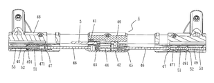
FIG. 7 is a three-dimensional view of the brake pole set of this invention;
FIG. 8 is a three-dimensional exploded view of the brake pole set of this invention;
FIG. 9 is an assembled sectional view of the brake pole set of this invention;
FIG. 10 is a schematic diagram of the motion of the hand brake control assembly during the braking of this invention;
FIG. 11 is a schematic sectional view (I) of the hand brake control assembly during the braking of this invention;
FIG. 12 is a schematic sectional view (II) of the hand brake control assembly during the braking of this invention;
FIG. 13 is a schematic sectional view of the brake pole set during the braking of this invention;
FIG. 14 is a schematic sectional view of the buffer mechanism during the braking of this invention; and
FIG. 15 is a three-dimensional view of this invention mounted on a golf bag cart.
DETAILED DESCRIPTION OF THE INVENTION
The structural trait and its function of this invention is described in detail with reference to the following two preferred embodiments and the accompanying drawings, which would give a thorough comprehension. Referring to FIGS. 3˜9, this invention comprises: a hand brake control assembly 2 fixed on the cart frame 3, a brake pole set 4 fixed on the rear wheel axle tube 30, and a brake wire 5 connecting the hand brake control assembly 2 and the rake pole set 4.
The hand brake control assembly 2 is shown in FIGS. 4˜6 and includes a body 20 fixed on the cart frame 3 and having a flag plug 21 at each top of its two sides. The flag plug 21 has a tilted arc at the top of its outer side and has an indent 22 at each top of its two inner sides. The body 20 is provided with a through hole 23 at its bottom, for penetration by the brake wire 5. A brake lug 24 is set up in the body 20 and has a camshaft 25 at each top of its two sides and in pinned connection with the corresponding flat plug 21. The camshaft 25 is provided with a fixing hole 26 below it, for fixing of one end of the brake wire 5. Two springy pushbuttons 27 are set up at both sides of the bottom of the lug 24 and join a threaded element 28 at their bottoms. The threaded element 28 is set up in the bottom of the lug 24 with a spring 29 put around it and which empowers the pushbuttons 27 to have a downward force. A clipping pin 31, set up in the top portion of the lug 24, is in threaded joining, at its middle, with the threaded element 28 which follows the move of the pushbutton 27. An adjustable screw 32 is set up in the through hole 23 at the bottom of the body 20, for penetration by the brake wire 5 and for adjustment of the tightness of the brake wire 5.
The brake pole set 4 is shown in FIGS. 7˜9 and includes a binder 40 fixed in the middle of the rear wheel axle tube 30 and having a cover 41 at its one end. A tie mount 42, L in shape, is set up in the binder 40 and has a long trough 421 on its surface. A slider 43 is set up on the long trough 421 of the tie mount 42, for penetration by the other end of the brake wire 5 through the cover 41 and the slider 43, followed by a fixing to the vertical part of the tie mount 42, to position the slider 43 in between the vertical part of the tie mount 42 and the binder 40. An extending pole 44 has one end penetrating the tie mount 42 for fixing and has the other end penetrating a continuing tube 45 for fixing. The continuing tube 45 is fixed in one end of the interior of the tie mount 42. Two linking poles 46 are set up at both sides of the tie mounts 42. Two buffer tins 47, shaping a ladder tube, are set up in the other end of the linking pole 46, which is located in a L-shape base 48. The L-shape base 48 joins the cart frame at its vertical end, shown in FIG. 3. Two brake poles 49, set up in the buffer tin 47 and the base 48, each has a protruded part 491 in its middle for separation purposes. The end of the brake pole 49 next to the protruded part 491 (the end next to the linking pole 46) is lodged in the buffer tin 47 and put around by a buffer spring 51, and a buffer space 471 is kept in the buffer tin 47. The other end of the brake pole 49 is lodged in the base 48 and put around by a spacer 52 and a brake spring 53. The aforementioned buffer tin 47, brake pole 49 and buffer spring 51 constitute a buffer mechanism, where the elasticity of the buffer spring 51 is less than that of the brake spring 53.
The brake wire 5, a steel rope, has one end penetrating the body 20 and fixedly joined to the lug 24 and has the other end penetrating the binder 40 and the slider 43 and fixedly joined to the tie mount 42.
According to the aforesaid structural combination, this invention is shown in FIGS. 3, 4, 6 & 9 in an integral form, where the brake lug 24 is pressed down to stick to the lower part of the body 20 and the spring 29 is in the stretched state. Also, the brake pole 49 is lodged in the base 48. The brake spring 53 and the buffer spring 51 are also in the stretched state. A buffer space 471 is kept with the brake pole 49 and the buffer spring 51 in the buffer tin 47. Once intending to brake, the lug 24 is lifted, which is by the tilt design for the outer sides of the body 20, and the lug 24 with the clipping pin 31 is pushed upward until a straight line is formed by the lug 24 and the body 20, shown in FIGS. 10˜12. Meanwhile, the brake wire 5 is drawn to move the tie mount 42 and the slider 43 toward the middle. As the buffer tin 47 and the brake pole 49 are pushed to move outward by the linking pole 46, the brake pole 49 protrudes from the base 48, shown in FIG. 13, for penetration into a hollow of the rear wheel 35 to halt rotation of the rear wheel 35, which results in braking to a stop. At this moment, the brake spring 53 is in a compressed state, the buffer spring 51 is in a stretched state, and the buffer space 471 still exists there. Once the brake lug 24 is pulled upward to its full extent and released, the clipping pin 31 moves down by the resilient force of the spring 29 and is clipped by the indent 22 of the body 20, shown in FIGS. 11 & 12, to achieve the automatic lock of the brake, which substantially prevents a lapse of releasing the brake by the user.
During braking a cart, a buffer mechanism is activated automatically if the brake pole 49 is not aligned with the hollow of the rear wheel 35. The brake pole 49 moves toward the buffer space 471 of the buffer tin 47 to compress the buffer spring 51 so that the brake pole 49 is still in the base 48, shown in FIG. 14. Once the rear wheel 35 is rotated to align the brake pole 49 with its hollow, the hollow is penetrated by the protruded brake pole 49 through the resilient force of the springs 51, 53, which therefore accomplishes the brake, shown in FIG. 9, and avoids destruction to the wheel 35 by the brake pole 49.
Accordingly, this invention has at least the following advantages and functions:
  • 1. The hand brake control assembly 2 is mounted on the cart frame 3, featuring a great visual sight and ease for operating.
  • 2. The hand brake control assembly 2 is provided with a safety design for the automatic lock, which substantially prevents a lapse of releasing the brake by the user.
  • 3. The brake pole set 4 is provided with a buffer mechanism, which avoids the destruction to the wheel 35 by the brake pole 49 during the incomplete operation of the brake.
Referring to FIG. 15, a hand brake control assembly 2′, a brake pole set 4′ and a brake wire 5′ of the brake apparatus of this invention is available to mount on a golf bag cart, to achieve the same function with the aforementioned exemplary embodiment. This is the other exemplary embodiment of this invention.
To sum up, the disclosed structures of the exemplary embodiments of this invention are absolutely novel to the prior art. It surely can accomplish the expected objective and function, which is construed as having not only novelty and creativeness but usefulness.

Claims (3)

1. A brake apparatus for carts with three or more wheels comprising:
a hand brake control assembly joined fixedly on a cart frame and having a body and a lug connected pivotally thereon, wherein the body is set up with an indent at an upper inner side, with the lug provided with a springy pushbutton at each of two lateral sides, where each springy pushbutton joins a threaded element at a bottom, with the threaded element joining a clipping pin at one end, with pulling on the lug, automatically locking the clipping pin and the indent with brake release being achieved by pressing the springy pushbuttons on both lateral sides of the lug to escape the clipping pin from the indent;
a brake pole set fixed on a rear wheel axle tube and having a binder provided with a tie mount in an interior, wherein the tie mount is provided with a slider, with the tie mount having a linking pole at each of two ends, wherein each linking pole joins a brake pole at one end and set up in a base and with a brake spring thereon; and
a brake wire having one end penetrating the body and fixedly joined with the lug and another end penetrating the binder and the slider and fixedly joined with the tie mount.
2. A brake apparatus for carts with three or more wheels as in claim 1 wherein the linking pole joins a buffer tin set up in the base at another end, with the brake pole having a protruded part at a middle for separation purposes, wherein the other end of the linking pole located beside the protruded part and lodged in the buffer tin is put around by a buffer spring and keeps a buffer space in the buffer tin and the end of the linking pole located beside the protruded part and lodged in the base being around by a spacer and the brake spring.
3. A brake apparatus for carts with three or more wheels as in claim 1 wherein the brake wire is a brake steel rope.
US12/575,541 2009-10-08 2009-10-08 Brake apparatus for carts with three or more wheels such as golf bag carts, baby strollers and the like Active 2030-10-30 US8205723B2 (en)

Priority Applications (1)

Application Number Priority Date Filing Date Title
US12/575,541 US8205723B2 (en) 2009-10-08 2009-10-08 Brake apparatus for carts with three or more wheels such as golf bag carts, baby strollers and the like

Applications Claiming Priority (1)

Application Number Priority Date Filing Date Title
US12/575,541 US8205723B2 (en) 2009-10-08 2009-10-08 Brake apparatus for carts with three or more wheels such as golf bag carts, baby strollers and the like

Publications (2)

Publication Number Publication Date
US20110083928A1 US20110083928A1 (en) 2011-04-14
US8205723B2 true US8205723B2 (en) 2012-06-26

Family

ID=43853952

Family Applications (1)

Application Number Title Priority Date Filing Date
US12/575,541 Active 2030-10-30 US8205723B2 (en) 2009-10-08 2009-10-08 Brake apparatus for carts with three or more wheels such as golf bag carts, baby strollers and the like

Country Status (1)

Country Link
US (1) US8205723B2 (en)

Cited By (3)

* Cited by examiner, † Cited by third party
Publication number Priority date Publication date Assignee Title
US20100187786A1 (en) * 2009-01-23 2010-07-29 Nuna International B.V. Buggy provided with a braking mechanism
US20140021697A1 (en) * 2012-07-10 2014-01-23 Combi Corporation Stroller
US11040736B1 (en) * 2020-01-13 2021-06-22 Emily Tejada Foldable shopping cart

Families Citing this family (4)

* Cited by examiner, † Cited by third party
Publication number Priority date Publication date Assignee Title
US20120085602A1 (en) * 2010-10-07 2012-04-12 Gordon Liao Braking Device of a Golf Bag Cart
CN202664579U (en) * 2012-06-04 2013-01-16 东莞市江顺箱包袋配件有限公司 Luggage wheel set brake system and control device
US10259483B2 (en) * 2016-08-10 2019-04-16 Diono, Llc Braking system for a stroller
CN112061186B (en) * 2020-08-31 2021-06-29 泉州市良创信息科技有限公司 Shallow with brake function

Citations (4)

* Cited by examiner, † Cited by third party
Publication number Priority date Publication date Assignee Title
US5460399A (en) * 1992-09-18 1995-10-24 Racing Strollers, Inc. Baby stroller with park brake
JPH09277938A (en) * 1996-04-16 1997-10-28 Shinwa Sangyo Kk Brake and stop lock mechanism for handcart
US6170615B1 (en) * 1999-03-29 2001-01-09 Hui-Fen Cheng Braking device of a three wheel baby car
US6341672B1 (en) * 2000-03-04 2002-01-29 Link Treasure Limited Braking device for a stroller

Patent Citations (4)

* Cited by examiner, † Cited by third party
Publication number Priority date Publication date Assignee Title
US5460399A (en) * 1992-09-18 1995-10-24 Racing Strollers, Inc. Baby stroller with park brake
JPH09277938A (en) * 1996-04-16 1997-10-28 Shinwa Sangyo Kk Brake and stop lock mechanism for handcart
US6170615B1 (en) * 1999-03-29 2001-01-09 Hui-Fen Cheng Braking device of a three wheel baby car
US6341672B1 (en) * 2000-03-04 2002-01-29 Link Treasure Limited Braking device for a stroller

Cited By (5)

* Cited by examiner, † Cited by third party
Publication number Priority date Publication date Assignee Title
US20100187786A1 (en) * 2009-01-23 2010-07-29 Nuna International B.V. Buggy provided with a braking mechanism
US8550478B2 (en) * 2009-01-23 2013-10-08 Nuna International B.V. Buggy provided with a braking mechanism
US20140021697A1 (en) * 2012-07-10 2014-01-23 Combi Corporation Stroller
US9283978B2 (en) * 2012-07-10 2016-03-15 Combi Corporation Stroller
US11040736B1 (en) * 2020-01-13 2021-06-22 Emily Tejada Foldable shopping cart

Also Published As

Publication number Publication date
US20110083928A1 (en) 2011-04-14

Similar Documents

Publication Publication Date Title
US8205723B2 (en) Brake apparatus for carts with three or more wheels such as golf bag carts, baby strollers and the like
AU2010235992B2 (en) Manually actuated brake system for manually towable vehicle
CA2855745C (en) Improved-model golf trolley
US6883814B2 (en) Cambering vehicle
US7490848B2 (en) Fixed-direction wheel control mechanism for baby stroller
CA2507724A1 (en) Brake handle assembly for walker
US20150069733A1 (en) Manual tractor assembly for tracking wheel chair
AU2013205917A1 (en) Folding golf cart
TWI611966B (en) Mechanical vehicle auxiliary system
US8418314B2 (en) Wheel assembly with a wheel lock structure
EP2065289A2 (en) A brake device for prams
FR2460831A1 (en) BICYCLE
KR20200012357A (en) Apparatus for walking assistance
US11447107B2 (en) Brake device
KR200421626Y1 (en) A cart braking device
KR20140102453A (en) Wheeled luggage
KR101932170B1 (en) Bicycles that can be connected to each other
CN107351887B (en) Folding handcart
CN106394759A (en) Suspension scooter
JP2001151118A (en) Handcart
JP2566534Y2 (en) Operating device for brake rod in stroller
JP3156492U (en) Wheelbarrow brake equipment
JP2010075328A (en) Carry bag having handle
JPH0780461B2 (en) Wheelbarrows for baby car, shopping car for the elderly, etc.
US20020093163A1 (en) Skate cart brake

Legal Events

Date Code Title Description
AS Assignment

Owner name: UNIQUE PRODUCT & DESIGN CO., LTD., TAIWAN

Free format text: ASSIGNMENT OF ASSIGNORS INTEREST;ASSIGNOR:LIAO, GORDON;REEL/FRAME:023343/0237

Effective date: 20091006

STCF Information on status: patent grant

Free format text: PATENTED CASE

FPAY Fee payment

Year of fee payment: 4

MAFP Maintenance fee payment

Free format text: PAYMENT OF MAINTENANCE FEE, 8TH YR, SMALL ENTITY (ORIGINAL EVENT CODE: M2552); ENTITY STATUS OF PATENT OWNER: SMALL ENTITY

Year of fee payment: 8

MAFP Maintenance fee payment

Free format text: PAYMENT OF MAINTENANCE FEE, 12TH YR, SMALL ENTITY (ORIGINAL EVENT CODE: M2553); ENTITY STATUS OF PATENT OWNER: SMALL ENTITY

Year of fee payment: 12