US8280636B2 - Method and system for controlling a well service rig based on load data - Google Patents
Method and system for controlling a well service rig based on load data Download PDFInfo
- Publication number
- US8280636B2 US8280636B2 US13/051,590 US201113051590A US8280636B2 US 8280636 B2 US8280636 B2 US 8280636B2 US 201113051590 A US201113051590 A US 201113051590A US 8280636 B2 US8280636 B2 US 8280636B2
- Authority
- US
- United States
- Prior art keywords
- load
- rig
- pipe
- stand
- tubing
- Prior art date
- Legal status (The legal status is an assumption and is not a legal conclusion. Google has not performed a legal analysis and makes no representation as to the accuracy of the status listed.)
- Active
Links
- 238000000034 method Methods 0.000 title claims abstract description 62
- 230000000007 visual effect Effects 0.000 claims description 6
- 230000003213 activating effect Effects 0.000 claims 5
- 230000008569 process Effects 0.000 description 16
- 230000000694 effects Effects 0.000 description 13
- 238000011156 evaluation Methods 0.000 description 13
- 230000005540 biological transmission Effects 0.000 description 9
- 230000001965 increasing effect Effects 0.000 description 9
- 230000002829 reductive effect Effects 0.000 description 8
- 230000008439 repair process Effects 0.000 description 7
- 230000000670 limiting effect Effects 0.000 description 6
- 238000010586 diagram Methods 0.000 description 5
- 230000001413 cellular effect Effects 0.000 description 4
- 230000006378 damage Effects 0.000 description 4
- 230000001133 acceleration Effects 0.000 description 3
- 230000008901 benefit Effects 0.000 description 3
- 241000269400 Sirenidae Species 0.000 description 2
- 208000027418 Wounds and injury Diseases 0.000 description 2
- 230000008878 coupling Effects 0.000 description 2
- 238000010168 coupling process Methods 0.000 description 2
- 238000005859 coupling reaction Methods 0.000 description 2
- 238000011161 development Methods 0.000 description 2
- 208000014674 injury Diseases 0.000 description 2
- 238000012986 modification Methods 0.000 description 2
- 230000004048 modification Effects 0.000 description 2
- 238000012544 monitoring process Methods 0.000 description 2
- 230000035484 reaction time Effects 0.000 description 2
- 238000012552 review Methods 0.000 description 2
- 230000003068 static effect Effects 0.000 description 2
- 238000012549 training Methods 0.000 description 2
- 230000005483 Hooke's law Effects 0.000 description 1
- 230000009471 action Effects 0.000 description 1
- 230000001174 ascending effect Effects 0.000 description 1
- 230000015572 biosynthetic process Effects 0.000 description 1
- 230000006835 compression Effects 0.000 description 1
- 238000007906 compression Methods 0.000 description 1
- 238000005553 drilling Methods 0.000 description 1
- 230000005284 excitation Effects 0.000 description 1
- 239000012530 fluid Substances 0.000 description 1
- 230000006870 function Effects 0.000 description 1
- 210000004907 gland Anatomy 0.000 description 1
- 230000001939 inductive effect Effects 0.000 description 1
- 238000009434 installation Methods 0.000 description 1
- 230000002147 killing effect Effects 0.000 description 1
- 230000013011 mating Effects 0.000 description 1
- 210000002445 nipple Anatomy 0.000 description 1
- 239000012188 paraffin wax Substances 0.000 description 1
- 238000011084 recovery Methods 0.000 description 1
- 230000009467 reduction Effects 0.000 description 1
- 230000002441 reversible effect Effects 0.000 description 1
- 238000005070 sampling Methods 0.000 description 1
- 238000012421 spiking Methods 0.000 description 1
- 230000000638 stimulation Effects 0.000 description 1
- 239000000126 substance Substances 0.000 description 1
- 238000012546 transfer Methods 0.000 description 1
- 238000011282 treatment Methods 0.000 description 1
Images


Classifications
-
- E—FIXED CONSTRUCTIONS
- E21—EARTH DRILLING; MINING
- E21B—EARTH DRILLING, e.g. DEEP DRILLING; OBTAINING OIL, GAS, WATER, SOLUBLE OR MELTABLE MATERIALS OR A SLURRY OF MINERALS FROM WELLS
- E21B19/00—Handling rods, casings, tubes or the like outside the borehole, e.g. in the derrick; Apparatus for feeding the rods or cables
Definitions
- the present invention generally pertains to equipment used for repairing wells that have already been drilled. More specifically the present invention pertains to an analysis of rig loads and rig load data to determine and monitor tubing and/or rod removal overload conditions on a well service rig.
- work-over and “service” operations are used in their very broadest sense to refer to any and all activities performed on or for a well to repair or rehabilitate the well, and also includes activities to shut in or cap the well.
- work-over operations include such things as replacing worn or damaged parts (e.g., a pump, sucker rods, tubing, and packer glands), applying secondary or tertiary recovery techniques, such as chemical or hot oil treatments, cementing the wellbore, and logging the wellbore, to name just a few.
- Service operations are usually performed by or involve a mobile work-over or well service rig (collectively hereinafter “service rig” or “rig”) that is adapted to, among other things, pull the well tubing or rods and also to run the tubing or rods back in to the well.
- service rig typically, these mobile service rigs are motor vehicle-based and have an extendible, jack-up derrick complete with draw works and block.
- a rig operator typically lifts a stand of tubing (or rods) which is then held in place by slips (or elevators for rods) while the stand is separated from the remaining portion of the tubing or rod string in the well.
- the stand of tubing can be placed on a tubing board.
- the weight or load on the hook can fluctuate greatly based on the weight of the tubing string in the well, the conditions within the well, the condition of the tubing string, and the amount of acceleration of the tubing string.
- the tubing string acts similarly to a rubber band. As the operator begins to accelerate the block upward and pull the tubing string out of the well.
- the tubing string initially becomes elongated for a short interval before the entire tubing string begins to move upward through the well.
- the same elongation can occur when a portion of the tubing string encounters a part of the well with increased friction or gets snagged or stuck within a portion of the well.
- the amount of load on the hook (“hookload”) can increase very quickly to a level that is above the safe operating level of the rig. While alarms can be employed, if the operator cannot act quickly enough, the rig may be damaged and workers around the well could be injured.
- the operator brings his engine RPM up to drive the tongs that are used to unscrew the tubing from one another.
- the operator engages the clutch for the hoist and lifts the stand of tubing about another foot or two and places it onto the tubing board.
- the lifting of the stand of tubing that small distance prior to placement on the tubing board can cause a small spike in the rig load recorded at the rig load sensors. Much of this spike is caused by the acceleration of the block by the operator.
- What is needed is a method and apparatus for evaluating the rig load or hookload of a service rig when removing tubing or rods from a well and disengaging the clutch for the hoist when the rig load reaches a level indicative of a problem with the tubing in the well, such as a snag or hang up. Furthermore, what is needed is a method and apparatus for evaluating the rig load or hookload of a tubing or rod string being removed from a well and limiting the speed of the block and hoist when only a small amount of tubing or rods remains in the well.
- the present invention is directed to solving these as well as other similar issues in the well service area.
- the present invention is directed to controlling the operation of a well service rig based on rig load data.
- rig load data By removing the need for or limiting the capabilities of the operator during situations of increased load on the well service rig the ability to prevent damage to the service rig and injury to the workers around the well head can be improved.
- speed of the well service rig during periods where only a small amount of tubing or rods remains to be pulled out of a wellbore, the opportunity for a dangerous situation caused by the tubing or rod hanging or getting caught up in the wellbore is reduced based on the fact that reaction time is increased at the slower speeds.
- a method for determining the average load during the pulling of a stand of rods or tubing can be achieved by monitoring the load data of a well service rig.
- the load data can be received during the removal process from sensors on the well service rig that transmit inputs to a computer or monitor on the rig.
- the computer can calculate the average load during the pull of a stand of tubing or rods based on the load data received from sensors.
- the load data can include the hookload or the load of the rig.
- the upper load limit can then be determined based on the computation of the average load.
- the upper load limit can be a fixed amount above the average load for each pull of a stand of tubing or rods or a percentage of the hookload or rig load.
- the upper load limit can then be set for the next pull of a stand of pipe from the well.
- the pipe can include, but is not limited to, pipe, well casing, rods, tubing, or other tubulars.
- a method for determining when to reduce or limit block and/or hoist speed during a pulling operation can be achieved based on an evaluation of hook load data.
- Load data can be received from sensors on the well service rig related to load calculations taken during the removal of a pipe string from a well.
- the hookload or rig load can be calculated based on the load data.
- An evaluation of the hookload or rig load can be conducted to determine if the load has fallen to or below a certain level. That level can be indicative that the weight of the remaining pipe string in the well is much less than when the pull operation first began.
- the speed of the block or the hoist can be limited to an speed that is substantially slower than the normal operation of the block and hoist during a standard pulling operation.
- the reduced speed can increase reaction time in case the pipe string becomes caught in the well.
- a method for preventing a well service rig from pulling a stand of pipe away from a pipe string while the stand of pipe is still engaged with the threads of the pipe string can be achieved based on an evaluation of rig load or hookload data.
- the system can receive information indicating that the rig is disengaging a stand of pipe from a pipe string, such as through the use of tongs.
- Load data such as rig load or hookload data can be received when the stand of pipe is being disengaged from the pipe string.
- An evaluation of the load data can be conducted to determine if the load data has increased above a certain level that is indicative of a stand of pipe being pulled up before the de-threading process has occurred from the pipe string. If the load level has increased to or above a certain level, the clutch for the drive system that is raising the stand of pipe can be disengaged automatically or the throttle can be reduced to prohibit over pulling.
- FIG. 1 is a side view of an exemplary mobile repair unit with its derrick extended according to one exemplary embodiment of the present invention
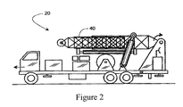
- FIG. 2 is a side view of the exemplary mobile repair unit with its derrick retracted according to one exemplary embodiment of the present invention
- FIG. 3 is an electrical schematic of a monitor circuit according to one exemplary embodiment of the present invention.
- FIG. 4 is an exemplary end view of an imbalanced derrick according to one exemplary embodiment of the present invention.
- FIG. 5 illustrates the raising and lowering of an inner tubing string with an exemplary mobile repair unit according to one exemplary embodiment of the present invention
- FIG. 6 illustrates one embodiment of an activity capture methodology outlined in tabular form according to one exemplary embodiment of the present invention
- FIG. 7 provides a frontal view of an exemplary operator interface according to one exemplary embodiment of the present invention.
- FIG. 8 is a flowchart of an exemplary process for identifying a rig load or hookload over limit event according to one exemplary embodiment of the present invention
- FIG. 9 is an exemplary display of a rig load data chart for determining rig load and/or hookload on a mobile repair unit according to one exemplary embodiment of the present invention.
- FIG. 10 is a flowchart of an exemplary process for determining the average rig load and/or hookload of a tubing string based on an evaluation of the rig load data chart according to one exemplary embodiment of the present invention
- FIG. 11 is an exemplary display of a portion of the rig load data chart for a single pull of tubing used to determine the average rig load and/or hookload of the tubing string in accordance with the exemplary embodiment of FIG. 10 .
- FIG. 12 is a flowchart of an exemplary process for determining the rig load and/or hookload limit based on an evaluation of the rig load data chart according to one exemplary embodiment of the present invention
- FIG. 13 is an exemplary display of the rig load data chart incorporating the average hookload and hookload limit in accordance with one exemplary embodiment of the present invention
- FIG. 14 is a flowchart of an exemplary process for limiting block speed during tubing removal by evaluating the exemplary rig load data charts according to one exemplary embodiment of the present invention.
- FIG. 15 is a flowchart of an exemplary process for preventing the pull of a stand of tubing before the tubing has been disengaged from the remaining tubing in the wellbore according to one exemplary embodiment of the present invention.
- a retractable, self-contained mobile repair unit 20 is shown to include a truck frame 22 supported on wheels 24 , an engine 26 , a hydraulic pump 28 , an air compressor 30 , a first transmission 32 , a second transmission 34 , a variable speed hoist 36 , a block 38 , an extendible derrick 40 , a first hydraulic cylinder 42 , a second hydraulic cylinder 44 , a first transducer 46 , a monitor 48 , and retractable feet 50 .
- the engine 26 selectively couples to the wheels 24 and the hoist 36 by way of the transmissions 34 and 32 , respectively.
- the engine 26 also drives the hydraulic pump 28 via the line 29 and the air compressor 30 via the line 31 .
- the compressor 30 powers a pneumatic slip (Not Shown), and pump powers a set of hydraulic tongs (Not Shown).
- the pump 28 also powers the cylinders 42 and 44 which respectively extend and pivot the derrick 40 to selectively place the derrick 40 in a working position, as shown in FIG. 1 , and in a lowered position, as shown in FIG. 2 . In the working position, the derrick 40 is pointed upward, but its longitudinal centerline 54 is angularly offset from vertical as indicated by the angle 56 .
- the angular offset provides the block 38 access to a wellbore 58 without interference with the derrick pivot point 60 .
- the derrick framework does not interfere with the typically rapid installation and removal of numerous inner pipe segments (known as pipe, inner pipe string, rods, or tubing 62 , hereinafter “tubing” or “rods”).
- hydraulic tongs refer to any hydraulic tool that can screw together two pipes or sucker rods.
- An example would include those provided by B.J. Hughes company of Houston, Tex.
- the pump 28 drives a hydraulic motor (Not Shown) forward and reverse by way of a valve.
- the motor drives the pinions which turn a wrench element relative to a clamp.
- the element and clamp engage flats on the mating couplings of a sucker rod or inner pipe string 62 of one conceived embodiment of the invention.
- the pneumatic slip is used to hold the tubing 62 while the next segment of tubing 62 is screwed on using tongs.
- a compressor 30 provides pressurized air through a valve to rapidly clamp and release the slip.
- a tank helps maintain a constant air pressure.
- Pressure switch provides monitor 48 ( FIG. 3 ) with a signal that indirectly indicates that rig 20 is in operation.
- the hydraulic pad 92 is basically a piston within a cylinder (alternatively a diaphragm) such as those provided M.D. Totco company of Cedar Park, Tex. Hydraulic pressure in the pad 92 increases with increasing weight on the block 38 .
- the first transducer 46 converts the hydraulic pressure to a 0-5 VDC signal 94 that is conveyed to the monitor 48 .
- the first transducer 46 can convert the hydraulic pressure into a 4-20 milliamp signal.
- the monitor 48 converts signal 94 to a digital value, stores it in a memory 96 , associates it with a real time stamp, and eventually communicates the data to a remote computer 100 or the computer 705 , of FIG. 7 , by way of hardwire, a modem 98 , T1 line, WiFi or other device or method for transferring data known to those of ordinary skill in the art.
- two pads 92 associated with two transducers 46 and 102 are used.
- An integrator 104 separates the pads 92 hydraulically.
- the rod side of the pistons 106 and 108 each have a pressure exposed area that is half the full face area of the piston 108 .
- the chamber 110 develops a pressure that is an average of the pressures in the pads 92 .
- One type of integrator 104 is provided by M.D. Totco company of Cedar Park, Tex.
- just one transducer 46 is used and it is connected to the port 112 .
- two transducers 46 and 102 are used, with the transducer 102 on the right side of the rig 20 coupled to the port 114 and the transducer 46 on the left side coupled to the port 116 .
- Such an arrangement allows one to identify an imbalance between the two pads 92 . While the foregoing has described the use of a pad 92 to determine load data, those of ordinary skill in the art will recognize that other types of load gauges can be used, including, but not limited to, strain gauges, line indicators and the like.
- transducers 46 and 102 are shown coupled to the monitor 48 .
- the transducer 46 indicates the pressure on the left pad 92 and the transducer 102 indicates the pressure on the right pad 92 .
- a generator 118 driven by the engine 26 provides an output voltage proportional to the engine speed. This output voltage is applied across a dual-resistor voltage divider to provide a 0-5 VDC signal at point 120 and then passes through an amplifier 122 .
- a generator 118 represents just one of many various tachometers that provide a feedback signal proportional to the engine speed. Another example of a tachometer would be to have engine 26 drive an alternator and measure its frequency.
- the transducer 80 provides a signal proportional to the pressure of hydraulic pump 28 , and thus proportional to the torque of the tongs.
- a telephone accessible circuit 124 referred to as a “POCKET LOGGER” by Pace Scientific, Inc. of Charlotte, N.C., includes four input channels 126 , 128 , 130 and 132 ; a memory 96 and a clock 134 .
- the circuit 124 periodically samples inputs 126 , 128 , 130 and 132 at a user selectable sampling rate; digitizes the readings; stores the digitized values; and stores the time of day that the inputs were sampled. It should be appreciated by those skilled in the art that with the appropriate circuit, any number of inputs can be sampled and the data could be transmitted instantaneously upon receipt.
- a supervisor at a computer 100 remote from the work site at which the service rig 20 is operating accesses the data stored in the circuit 124 by way of a PC-based modem 98 and a cellular phone 136 or other known methods for data transfer.
- the phone 136 reads the data stored in the circuit 124 via the lines 138 (RJ11 telephone industry standard) and transmits the data to the modem 98 by way of antennas 140 and 142 .
- the data is transmitted by way of a cable modem or WiFi system (Not Shown).
- the phone 136 includes a CELLULAR CONNECTIONTM provided by Motorola Incorporated of Schaumburg, Ill. (a model S1936C for Series II cellular transceivers and a model S1688E for older cellular transceivers).
- the amplifiers 122 , 144 , 146 and 148 condition their input signals to provide corresponding inputs 126 , 128 , 130 and 132 having an appropriate power and amplitude range. Sufficient power is needed for RC circuits 150 which briefly (e.g., 2-10 seconds) sustain the amplitude of inputs 126 , 128 , 130 and 132 even after the outputs from transducers 46 , 102 and 80 and the output of the generator 118 drop off.
- a DC power supply 152 provides a clean and precise excitation voltage to the transducers 46 , 102 and 80 ; and also supplies the circuit 124 with an appropriate voltage by way of a voltage divider 154 .
- a pressure switch 90 enables the power supply 152 by way of the relay 156 , whose contacts 158 are closed by the coil 160 being energized by the battery 162 .
- FIG. 5 presents an exemplary display representing a service rig 20 lowering an inner pipe string 62 as represented by arrow 174 of FIG. 5 .
- FIG. 6 provides an illustration of an activity capture methodology in tabular form according to one exemplary embodiment of the present invention.
- an operator first chooses an activity identifier for his/her upcoming task. If “GLOBAL” is chosen, then the operator would choose from rig up/down, pull/run tubing or rods, or laydown/pickup tubing and rods (options not shown in FIG. 6 ).
- ROUTINE INTERNAL
- the operator would choose from rigging up or rigging down an auxiliary service unit, longstroke, cut paraffin, nipple up/down a BOP, fishing, jarring, swabbing, flowback, drilling, clean out, well control activities such as killing the well or circulating fluid, unseating pumps, set/release tubing anchor, set/release packer, and pick up/laydown drill collars and/or other tools.
- ROUTINE EXTERNAL
- the operator would then select an activity that is being performed by a third party, such as rigging up/down third party servicing equipment, well stimulation, cementing, logging, perforating, or inspecting the well, and other common third party servicing tasks. After the activity is identified, it is classified. For all classifications other than “ON TASK: ROUTINE,” a variance identifier is selected, and then classified using the variance classification values.
- FIG. 7 provides a view of an rig operator interface or supervisor interface according to one exemplary embodiment of the present invention.
- the operator can interface with the computer 705 using a variety of means, including typing on a keyboard 725 or using a touch-screen 710 .
- a display 710 with pre-programmed buttons, such as pulling rods or tubing from a wellbore 715 is provided to the operator, as shown in FIG. 7 , which allows the operator to simply select the activity from a group of pre-programmed buttons. For instance, if the operator were presented with the display 710 of FIG.
- the operator upon arriving at the well site, the operator would first press the “RIG UP” button. The operator would then be presented with the option to select, for example, “SERVICE UNIT,” “AUXILIARY SERVICE UNIT,” or “THIRD PARTY.” The operator then would select whether the activity was on task, or if there was an exception, as described above.
- the operator prior to pulling (removing) 715 or running (inserting) tubing 62 , the operator could set the high and low limits for the block 38 by pressing the learn high or learn low buttons after moving the block 38 into the proper position.
- FIG. 8 a logical flowchart diagram illustrating an exemplary method 800 for identifying an over load limit event on a service rig 20 based on an evaluation of the rig load data chart is presented according to one exemplary embodiment of the present invention.
- the exemplary method 800 begins at the START step and continues to step 805 , where an inquiry is conducted to determine if the drum clutch for the variable speed hoist 36 is engaged. If the clutch is not engaged, the “NO” branch is followed back to step 805 until a determination is made that the clutch is engaged. Otherwise, the “YES” branch is followed to step 810 .
- step 810 an inquiry is conducted to determine if the rig load weight is above the baseline weight or load level.
- the baseline weight is generally at a level that is marginally above the weight of the rig itself. In one exemplary embodiment, the baseline weight is approximately 40,000 pounds. However, those of skill in the art will recognize that this amount may be easily changed based on other factors, such as rig size, well conditions, etc. In an alternative embodiment, there may not be a need for an evaluation of the baseline weight, as any rig load limit weight will generally be above the baseline weight. If the weight is not above the baseline weight, the “NO” branch is followed back to step 805 . On the other hand, if the rig load weight is above the baseline weight, the “YES” branch is followed to step 815 .
- step 815 an inquiry is conducted to determine if the blocks 38 are moving in the direction to remove tubing 62 from the wellbore 58 .
- the direction of the blocks 38 can be analyzed by positioning an encoder (Not Shown) at the hoist 36 or at another position along the line coupled to the block 38 . If the block 38 is not moving in the direction for removing the tubing 62 , the “NO” branch is followed to step 805 . Otherwise, the “YES” branch is followed to step 820 .
- step 820 an inquiry is conducted to determine if the slips at the wellhead 68 are open.
- the slips are used when pulling tubing 62 out of the well 58 .
- the tubing 62 is set on the slips, which suspend the remaining tubing 62 at the wellhead 186 and down in the wellbore 58 .
- the slips are engaged into position through the use of pneumatic pressure.
- the position of the slips can be determined through the use of a pneumatic switch that sense if opening or closing air pressure is being applied to the slips.
- the position of the slips can be evaluated using a slip sensor to evaluate and open/closed position.
- the slip sensor can include a pressure-type input/output switch.
- Those of ordinary skill in the art will recognize that other methods of determine the position of the slips can also be employed, including photoeyes, proximity sensors and other positional indicators. If the slips are not open, the “NO” branch is followed to step 805 . If the slips are open, the “YES” branch is followed to step 825 .
- FIG. 9 is an illustration of an exemplary display 900 of a rig load data chart presenting the rig load weight data and used for determining the rig load of a mobile repair unit 20 .
- the exemplary display 900 includes a rig load data chart 905 .
- the X-axis of the rig load data chart 905 represents time and the Y-axis represents rig load in pounds. Rig load can be measured at several places on the rig 20 .
- rig load can be measured on each individual rig pad 92 , on a transducer or sensor on the output side of the integrator on the pad weight indicator (Not Shown), on a strain gage placed on the mast of the rig 20 to measure compression in a derrick leg, on a dead line, line sensor, line diaphragm, sending diaphragm or cylinder (Not Shown).
- the rig load displayed in the rig load chart 905 is based on the total weight on the pads 92 , not the load on the hook 38 (“hookload”).
- FIG. 9 presents the general patterns for rig load data curves during activities for pulling rods and tubing 62 out of a wellbore 58 .
- the rig load chart 905 includes a series of rig load data points represented as a weight curve 910 . While it appears from the weight curve 910 that the rig load data points are being recorded on a constant basis, it is possible to take the data points at intervals and generate the line based on averages over a period of data points.
- the rig load chart 905 presents data such as the weight of the rig 20 , which can be determined by evaluating the valleys 915 of the data points.
- the chart 905 also presents spikes 920 of the rig load level.
- the amount of the spike 920 can be based on several factors, including, but not limited to, the speed at which the tubing 62 is being removed from the well 58 , anomalies or wear within the wellbore 58 , or problems with the tubing 62 in the wellbore 58 .
- the computer 705 determines the average weight of the rig load based on the data in the rig load chart 905 in step 830 .
- the computer 705 determines the rig load limit.
- the rig load limit is the amount of load above the average weight of the rig load that the rig 20 can pull and still operate safely. For example, as long as the actual load received at the sensors 92 does not exceed the rig load limit, the rig 20 can continue to operate. However, if the sensors 92 read a load that is greater than or equal to the rig load limit, the pulling of the tubing 62 can be stopped by disengaging the clutch for the hoist 36 .
- the rig load limit is a constant value above the average weight for the rig load, for example a value between five and fifty thousand pounds.
- the rig load limit is a percentage of the average rig load for the prior tubing pull that is added to that average rig load, for example between 1-50 percent.
- the rig load limit is a percentage of the hookload that is added to the average rig load for the prior tubing pull, for example between 1-500% of the hookload.
- the hookload can be determined by subtracting the rig weight on its own from the average rig load. The value of the rig weight on its own may be known, or may be determined by taking the value at the valley 915 of the data curve 910 for one of the prior tubing pulls.
- step 840 an inquiry is conducted to determine if the rig load level is above the rig load limit.
- the current rig load level may be determined at the sensor 92 or by monitoring the data curve 910 on the chart 905 . If the rig load level is not above the rig load limit, the “NO” branch is followed back to step 825 to continue recording rig load data at the computer 705 . However, if the rig load level is above the rig load limit, the “YES” branch is followed to step 845 , where the computer 705 sends a signal to apply the brake and disengage the clutch of the hoist 36 and reduce the engine throttle or any combination thereof, thereby stopping any additional pulling of the tubing 62 out of the wellbore 58 .
- the computer 705 sends a signal to activate an alarm and records the overload event for subsequent analysis and training of the rig operator.
- the alarm may be audible, visual or both.
- Audible alarms include, but are not limited to, sirens, horns and the like.
- Visual alarms may include, but are not limited to, flashing lights, a light turning on, or a display of a message at the computer 705 .
- the process then continues to the END step.
- FIG. 10 is a logical flowchart diagram illustrating the exemplary method 830 for determining the average rig load based on an evaluation of the rig load data chart 905 according to one exemplary embodiment of the present invention.
- the exemplary method 830 begins at step 1005 , where a determination is made as to the start time for pulling a stand of tubing 62 .
- the start time for pulling is determined to be when the clutch of the hoist 36 is engaged, the weight is above the baseline weight, the block 38 is moving upward, and the slips are open, however, fewer than all of these elements and/or different elements may be analyzed to determine the start time of the pull.
- FIG. 11 presents the a display 1100 of the general pattern for a rig load data curve 1110 while pulling a single stand of tubing 62 from the starting point to the completion point from the wellbore 58 .
- FIG. 11 also includes a static expected weight curve 1110 superimposed onto the rig load data curve 1105 .
- the static expected weight curve 1110 is a best case scenario for load generated at the rig load sensors 92 during the pulling of a stand of tubing 62 .
- the rig load data curve 1105 can be divided into multiple intervals, in order to separate good data from data containing a large amount of error.
- the rig load data 1105 can be divided up into three intervals: the first interval 1115 , the second interval 1120 , and the third interval 1125 ; however, greater or fewer intervals are within the scope of this invention.
- the curve 1105 is reflective of Hooke's law, or the spring action of the tubing 62 . If the operator pulls off the slips too fast or has a running start before the elevators engage the tubing collar, the peak at point 1105 will increase above the actual weight due to momentum. Additionally, not allowing the hoist chain sprocket and right angle drive (Not Shown) to come to a stop prior to engaging the clutch for the hoist 36 will cause the peak at 1105 to increase as well. In one exemplary embodiment, the first time interval will be between one and five seconds, however adjustments to the interval length may be made based on the length of tubing 62 remaining on the string, the amount of acceleration, and the condition of the wellbore 58 .
- the second interval 1120 is the most reflective of the true rig load.
- the slope of the rig load data curve 1105 during the second interval 1120 is normally positive because the block speed is increasing, however, the slope can be zero if the block speed is constant.
- the third interval 1125 is the interval with the fastest ascending tubing 62 speed.
- the data 1105 during the third interval can be reflective of swabbing the hole.
- the increase in the apparent weight during the third interval 1125 is typically due to drag and speed of the tubing 62 .
- the first predetermined amount of time is between one and five seconds.
- the first predetermined amount of time is a percentage of the entire time period to pull a single stand of tubing 62 from the start point to the completion point. In this exemplary embodiment, the percentage can be between 1-40 percent of the entire time period.
- the rig load data for the second predetermined amount of time, or third interval 1125 is removed from the analysis of the average rig load.
- the third interval 1125 can be a percentage of the overall time period to pull the stand of tubing 62 . In this exemplary embodiment, the percentage can be between 1-40 percent of the entire time period.
- the computer 705 averages the remaining rig load data 1105 to determine an average rig load. In one exemplary embodiment, the remaining rig load data includes only the data 1105 plotted during the second interval 1120 . The process then continues to step 835 of FIG. 8 .
- FIG. 12 is a logical flowchart diagram illustrating the exemplary method 835 of FIG. 8 for determining the rig load limit based on an evaluation of the rig load data chart 905 according to one exemplary embodiment of the present invention.
- the exemplary method 835 begins at step 1105 , where the average rig load is received.
- the average rig load is determined by the computer 705 ; however, the average rig load can be manually entered into the computer 705 by the operator of the rig 20 .
- the average rig load is reduced by the weight of the rig 20 in step 1210 .
- the weight of the rig can be determined prior to pulling the tubing 62 or manually input by the rig operator.
- the rig weight can be determined by receiving the minimum rig load data point 915 of FIG. 9 , on the prior pull of a stand of tubing 62 and that amount can be deducted from the average rig load to determine the hookload or weight of tubing 62 in the tubing string 62 .
- an additional load amount is determined.
- the additional load amount is a consistent amount of weight, for example, between five thousand and fifty thousand pounds.
- the amount of additional load is based on a predetermined percentage of the hookload, for example between 1 and 500 percent of the hookload. In yet another exemplary embodiment, the amount of additional load is based on a predetermined percentage of the average rig load, for example between 1-50 percent of average rig load. In this exemplary embodiment, since the additional load is based on the average rig load, there is no need to determine the weight of the rig or to subtract the weight of the rig from the average rig load. In each of these embodiments, the additional load can be considered a load safety factor.
- step 1220 the load safety factor is added to the average rig load for the most recent pull of a stand of tubing 62 .
- the sum of the load safety factor and the average rig load are set as the rig load limit for the pull of the next stand of tubing 62 .
- the process continues for each subsequent stand of tubing 62 until all of the tubing 62 has been removed from the wellbore 58 .
- the process continues from step 1225 to step 840 of FIG. 8 .
- FIG. 13 is an illustration of an exemplary display 1300 of a rig load data chart 1305 presenting the general patterns for exemplary rig load data curves at the computer 705 while stands of tubing 62 are being removed from the wellbore 58 in accordance with one exemplary embodiment of the present invention.
- the exemplary display 1300 includes a rig load data chart 1305 substantially as described with regards to FIG. 9 .
- the rig load data chart includes rig load data 1310 presented as a data curve; however, those of ordinary skill in the art will recognize that the data 1310 could also be individual points plotted on a graph without connection in the manner of a curve.
- the chart 1305 also includes a series of data points 1320 , substantially shown in the shape of a straight line, representing the average rig load determined generally as described in FIG. 10 . Furthermore, the chart 1305 includes a series of data points 1315 , substantially presented in the shape of a straight line, representing the rig load limit, which is determined as generally described in FIG. 12 .
- a series of data points 1320 and the rig load limit 1315 onto the chart 1305 of rig load data 1310 an operator can better determine the number of times that he has pushed the rig load over the rig load limit 1315 .
- FIG. 14 is a logical flowchart diagram illustrating an exemplary method 1400 for limiting block speed during tubing 62 removal by evaluating the exemplary rig load data in the rig load data chart according to one exemplary embodiment of the present invention.
- the exemplary method 1400 begins at the START step and continues to step 1405 , where the computer 705 receives notification that the rig 20 is pulling out of the wellbore 58 with tubing 62 .
- the notification can take the form of steps 805 - 820 of FIG. 8 .
- the notification can be based on the rig operator selecting the pull activity 715 at the computer 705 .
- the average rig load is determined in step 830 and is described in greater detail in FIG. 10 .
- the computer 705 receives the average rig load for the most recent pull of a stand of tubing 62 .
- an inquiry is conducted to determine if the average rig load has reached a predetermined level.
- the predetermined level can be set at a hookload of between one and fifty thousand pounds.
- the hookload can be added to the known or expected weight of the rig 20 to insert the predetermined level as a rig load, for example approximately 42,500 pounds in the example of FIG. 9 (hookload of 5000 pounds plus rig weight of 37,500 pounds).
- the computer 705 can determine the average hookload during each tubing pull by subtracting the rig weight from the average rig load and can compare the average hookload to the predetermined level of hookload.
- step 1425 If the average rig load has not reached a predetermined level, then the “NO” branch is followed to step 1425 , where additional stands of tubing 62 are removed with the operator having the complete range of speed control available. The process then returns to step 830 to determine the average rig load for the most current tubing pull. If the average rig load has reached the predetermined level, then the “YES” branch is followed to step 1430 , where the computer 705 transmits a signal to limit block speed while pulling the remaining stands of tubing 62 . The signal generally acts as a governor for the drive of the hoist 36 .
- the standard speed for removal of tubing 62 is approximately six feet per second and the limited block speed has a maximum of anywhere between one-half and four feet per second after the predetermined rig load is reached.
- the slippage in the transmission 32 can also be increased for the hoist 36 .
- the slippage in the transmission 32 can be increased by opening a solenoid valve (Not Shown) on the first transmission 32 case thereby relieving hydraulic pressure in the transmission lockup system. The reduction in hydraulic pressure induces slippage into the first transmission 32 and thereby offers another level of safety in case the rig 20 pulls tubing 62 that unexpectedly gets hung up on something in the wellbore 58 .
- the air pressure applied to the hoist clutch bladder can be reduced, thereby inducing slippage in the hoist clutch.
- the clutch bladder generally is provided with an air pressure in excess of one hundred pounds per square inch when a hoist 36 is operating normally with a load. This air pressure can be reduced to induce the slippage described above and provide another level of safety in case the tubing 62 is hung up in the wellbore 58 . The process then continues to the END step. While the present method has been described generally in terms of the rig load, those of ordinary skill in the art will recognize that, with minor modifications as discussed herein, the hookload could be substituted for the rig load in most instances.
- FIG. 15 is a logical flowchart diagram illustrating an exemplary method 1500 for preventing the pull of a stand of tubing 62 before the tubing 62 has been disengaged from the remaining tubing 62 in the wellbore 58 according to one exemplary embodiment of the present invention.
- the exemplary method 1500 begins at the START step and continues to step 1505 , where an inquiry is conducted to determine if the clutch of the first transmission 32 driving the variable speed hoist 36 is engaged. If the clutch is not engaged, the “NO” branch is followed back to step 1505 until a determination is made that the clutch is engaged. Otherwise, the “YES” branch is followed to step 1510 .
- step 1510 an inquiry is conducted to determine if the rig load weight is above the baseline level.
- the baseline weight is generally at a level that is marginally above the weight of the rig 20 itself.
- the baseline weight is approximately 40,000 pounds. However, those of skill in the art will recognize that this amount may be easily changed based on other factors, as described above. In an alternative embodiment, there may not be a need for an evaluation of the baseline weight, as any rig load limit weight will generally be above the baseline weight. If the weight is not above the baseline weight, the “NO” branch is followed back to step 1505 . On the other hand, if the rig load weight is above the baseline weight, the “YES” branch is followed to step 1515 .
- step 1520 an inquiry is conducted to determine if the blocks 38 are moving in the direction to remove tubing 62 from the wellbore 58 .
- the direction of the blocks 38 can be analyzed by positioning an encoder at the hoist 36 or at another position along the line coupled to the block 38 . If the block 38 is not moving in the direction for removing the tubing 62 , the “NO” branch is followed to step 1505 . Otherwise, the “YES” branch is followed to step 1520 .
- step 1520 an inquiry is conducted to determine if the slips (Not Shown) at the wellhead 186 are closed during a tubing pull or if the elevator (Not Shown) is in use during a rod pull. If the slips are open or the elevator is not in use for the rod pull, the “NO” branch is followed to step 1505 . Otherwise, the “YES” branch is followed to step 1525 .
- the computer 705 evaluates the rig load data.
- the computer 705 can evaluate the raw data from the sensor 92 , data that has been “cleansed,” or it can review the data points on the chart 905 .
- an inquiry is conducted to determine if the rig load is above a predetermined level.
- the predetermined level is a hookload of between two and ten thousand pounds or a rig load having a predetermined level of between two and ten thousand pounds plus the weight or estimated weight of the rig 20 .
- the weight of the rig 20 can be manually input at the computer 705 or determined based on an evaluation of the lower limits of the rig load data 915 on the rig load data chart 905 .
- step 1525 If the rig load is not above the predetermined level, the “NO” branch is followed to step 1525 to continue evaluation of the rig load data. On the other hand, if the rig load is above the predetermined level, the “YES” branch is followed to step 1535 , where the computer 705 transmits a signal to apply the brake and disengage the clutch for the hoist 36 and block 38 , thereby stopping any additional pulling of the tubing 62 out of the wellbore 58 .
- An alarm is initiated and an overload event is recorded in step 1540 for subsequent analysis and training of the rig operator.
- the alarm may be audible, visual or both. Audible alarms include, but are not limited to, sirens, horns and the like. Visual alarms may include, but are not limited to, flashing lights, a light turning on, or a display of a message at the computer 705 .
- the process continues from step 1540 to the END step.
Abstract
Description
Claims (20)
Priority Applications (2)
| Application Number | Priority Date | Filing Date | Title |
|---|---|---|---|
| US13/051,590 US8280636B2 (en) | 2007-09-05 | 2011-03-18 | Method and system for controlling a well service rig based on load data |
| US13/561,321 US20130032358A1 (en) | 2007-09-05 | 2012-07-30 | Method And System For Controlling A Well Service Rig Based On Load Data |
Applications Claiming Priority (2)
| Application Number | Priority Date | Filing Date | Title |
|---|---|---|---|
| US11/850,398 US7917293B2 (en) | 2007-09-05 | 2007-09-05 | Method and system for controlling a well service rig based on load data |
| US13/051,590 US8280636B2 (en) | 2007-09-05 | 2011-03-18 | Method and system for controlling a well service rig based on load data |
Related Parent Applications (1)
| Application Number | Title | Priority Date | Filing Date |
|---|---|---|---|
| US11/850,398 Division US7917293B2 (en) | 2007-09-05 | 2007-09-05 | Method and system for controlling a well service rig based on load data |
Related Child Applications (1)
| Application Number | Title | Priority Date | Filing Date |
|---|---|---|---|
| US13/561,321 Division US20130032358A1 (en) | 2007-09-05 | 2012-07-30 | Method And System For Controlling A Well Service Rig Based On Load Data |
Publications (2)
| Publication Number | Publication Date |
|---|---|
| US20110214856A1 US20110214856A1 (en) | 2011-09-08 |
| US8280636B2 true US8280636B2 (en) | 2012-10-02 |
Family
ID=40408774
Family Applications (3)
| Application Number | Title | Priority Date | Filing Date |
|---|---|---|---|
| US11/850,398 Active 2027-12-23 US7917293B2 (en) | 2007-09-05 | 2007-09-05 | Method and system for controlling a well service rig based on load data |
| US13/051,590 Active US8280636B2 (en) | 2007-09-05 | 2011-03-18 | Method and system for controlling a well service rig based on load data |
| US13/561,321 Abandoned US20130032358A1 (en) | 2007-09-05 | 2012-07-30 | Method And System For Controlling A Well Service Rig Based On Load Data |
Family Applications Before (1)
| Application Number | Title | Priority Date | Filing Date |
|---|---|---|---|
| US11/850,398 Active 2027-12-23 US7917293B2 (en) | 2007-09-05 | 2007-09-05 | Method and system for controlling a well service rig based on load data |
Family Applications After (1)
| Application Number | Title | Priority Date | Filing Date |
|---|---|---|---|
| US13/561,321 Abandoned US20130032358A1 (en) | 2007-09-05 | 2012-07-30 | Method And System For Controlling A Well Service Rig Based On Load Data |
Country Status (6)
| Country | Link |
|---|---|
| US (3) | US7917293B2 (en) |
| AR (1) | AR068227A1 (en) |
| CA (2) | CA2639345C (en) |
| MX (1) | MX2008011320A (en) |
| RU (1) | RU2445440C2 (en) |
| WO (1) | WO2009032889A1 (en) |
Cited By (3)
| Publication number | Priority date | Publication date | Assignee | Title |
|---|---|---|---|---|
| WO2015164911A1 (en) * | 2014-04-28 | 2015-11-05 | Drill Rig Spares Pty Ltd | Rod rotation apparatus |
| US9458683B2 (en) | 2012-11-19 | 2016-10-04 | Key Energy Services, Llc | Mechanized and automated well service rig system |
| US11112296B2 (en) * | 2019-04-12 | 2021-09-07 | Schlumberger Technology Corporation | Downhole tool string weight measurement and sensor validation |
Families Citing this family (17)
| Publication number | Priority date | Publication date | Assignee | Title |
|---|---|---|---|---|
| US8326538B2 (en) * | 2008-12-30 | 2012-12-04 | Occidental Permian Ltd. | Mobile wellsite monitoring |
| NL2003406C2 (en) * | 2009-08-28 | 2011-03-01 | Heerema Marine Contractors Nl | Improved hoisting assembly. |
| US8589036B2 (en) * | 2010-06-17 | 2013-11-19 | Key Energy Services, Llc | Method and system for automatically setting, adjusting, and monitoring load-based limits on a well service rig |
| CA2756544A1 (en) * | 2010-10-27 | 2012-04-27 | Key Energy Services, Llc | Method and system for evaluating sensor data from a well service rig |
| US20120203462A1 (en) * | 2011-02-08 | 2012-08-09 | Pile Dynamics, Inc. | Pile installation and monitoring system and method of using the same |
| US8863846B2 (en) * | 2012-01-31 | 2014-10-21 | Cudd Pressure Control, Inc. | Method and apparatus to perform subsea or surface jacking |
| US9416652B2 (en) | 2013-08-08 | 2016-08-16 | Vetco Gray Inc. | Sensing magnetized portions of a wellhead system to monitor fatigue loading |
| RU2566646C2 (en) * | 2014-02-19 | 2015-10-27 | Федеральное государственное бюджетное образовательное учреждение высшего образования "Тюменский государственный нефтегазовый университет" (ТюмГНГУ) | Lab unit to define stress at drill bit |
| NO20140477A1 (en) | 2014-04-11 | 2015-10-12 | Mera As | System and method for status monitoring of an on-site hydraulic system |
| US10746008B2 (en) | 2015-11-24 | 2020-08-18 | Saudi Arabian Oil Company | Weight on bit calculations with automatic calibration |
| BR112022018100A2 (en) | 2020-03-10 | 2022-10-25 | Joy Global Surface Mining Inc | INDUSTRIAL DRILL FOR MINING OPERATIONS, SYSTEM AND METHOD FOR DETECTING A CONDITION OF A PIPE OF AN INDUSTRIAL DRILL |
| RU2746953C1 (en) * | 2020-09-08 | 2021-04-22 | Публичное акционерное общество "Газпром нефть" (ПАО "Газпром нефть") | Method for determining the sludging of the wellbore |
| US11339612B1 (en) | 2021-10-08 | 2022-05-24 | Frederic M Newman | Electric well service rig |
| US11448050B1 (en) | 2021-10-08 | 2022-09-20 | Frederic M Newman | Universal electric well service rig |
| US11401797B1 (en) | 2021-10-08 | 2022-08-02 | Frederic M Newman | Electric well service rig for ESP installations |
| US11572260B1 (en) | 2022-05-03 | 2023-02-07 | Frederic M Newman | Electric well service rig with speed limiter |
| US11674365B1 (en) | 2023-02-14 | 2023-06-13 | Frederic M Newman | Battery shuttle for electric well service rigs |
Citations (12)
| Publication number | Priority date | Publication date | Assignee | Title |
|---|---|---|---|---|
| US2176885A (en) | 1937-07-14 | 1939-10-24 | Mineral Cutting Machine Compan | Mining apparatus |
| US2582987A (en) | 1950-01-26 | 1952-01-22 | Goodman Mfg Co | Power winch or hoist |
| US3917230A (en) * | 1972-01-24 | 1975-11-04 | Byron Jackson Inc | Well drilling control system |
| US3942594A (en) | 1972-10-04 | 1976-03-09 | Drill-Au-Mation, Inc. | Drill pipe monitoring system |
| US4128888A (en) | 1977-03-15 | 1978-12-05 | Bj-Hughes Inc. | Velocity control arrangement for a computer-controlled oil drilling rig |
| US4139891A (en) | 1977-03-15 | 1979-02-13 | Bj-Hughes Inc. | Elevator load control arrangement for a computer-controlled oil drilling rig |
| US4187546A (en) | 1977-03-15 | 1980-02-05 | B. J. Hughes Inc. | Computer-controlled oil drilling rig having drawworks motor and brake control arrangement |
| US20040068394A1 (en) | 2002-10-08 | 2004-04-08 | Fanuc Ltd. | Apparatus for detecting or predicting tool breakage |
| US20040065874A1 (en) | 2002-10-03 | 2004-04-08 | Newman Frederic M. | Engine speed limiter for a hoist |
| US20050199388A1 (en) | 2004-02-27 | 2005-09-15 | Key Energy Services, Inc. | Safemode operating system for a drilling or service rig |
| US20050216116A1 (en) | 2004-03-29 | 2005-09-29 | Nield Barry J | Microprocessor integrated multifunction hoist system controller |
| US20070056727A1 (en) | 2005-09-13 | 2007-03-15 | Key Energy Services, Inc. | Method and system for evaluating task completion times to data |
Family Cites Families (3)
| Publication number | Priority date | Publication date | Assignee | Title |
|---|---|---|---|---|
| US2068638A (en) * | 1927-08-24 | 1937-01-19 | Harry T Nichols | Combined crown and traveling block |
| US2657011A (en) * | 1950-04-01 | 1953-10-27 | Continental Supply Company | Means for controlling hoists and winches |
| RU2162133C1 (en) * | 2000-03-28 | 2001-01-20 | Закрытое акционерное общество НПАК "РАНКО" | Mobile repair and drilling rig |
-
2007
- 2007-09-05 US US11/850,398 patent/US7917293B2/en active Active
-
2008
- 2008-09-02 CA CA2639345A patent/CA2639345C/en not_active Expired - Fee Related
- 2008-09-02 CA CA2845206A patent/CA2845206C/en not_active Expired - Fee Related
- 2008-09-04 RU RU2010112713/03A patent/RU2445440C2/en not_active IP Right Cessation
- 2008-09-04 MX MX2008011320A patent/MX2008011320A/en active IP Right Grant
- 2008-09-04 WO PCT/US2008/075200 patent/WO2009032889A1/en active Application Filing
- 2008-09-05 AR ARP080103884A patent/AR068227A1/en unknown
-
2011
- 2011-03-18 US US13/051,590 patent/US8280636B2/en active Active
-
2012
- 2012-07-30 US US13/561,321 patent/US20130032358A1/en not_active Abandoned
Patent Citations (12)
| Publication number | Priority date | Publication date | Assignee | Title |
|---|---|---|---|---|
| US2176885A (en) | 1937-07-14 | 1939-10-24 | Mineral Cutting Machine Compan | Mining apparatus |
| US2582987A (en) | 1950-01-26 | 1952-01-22 | Goodman Mfg Co | Power winch or hoist |
| US3917230A (en) * | 1972-01-24 | 1975-11-04 | Byron Jackson Inc | Well drilling control system |
| US3942594A (en) | 1972-10-04 | 1976-03-09 | Drill-Au-Mation, Inc. | Drill pipe monitoring system |
| US4128888A (en) | 1977-03-15 | 1978-12-05 | Bj-Hughes Inc. | Velocity control arrangement for a computer-controlled oil drilling rig |
| US4139891A (en) | 1977-03-15 | 1979-02-13 | Bj-Hughes Inc. | Elevator load control arrangement for a computer-controlled oil drilling rig |
| US4187546A (en) | 1977-03-15 | 1980-02-05 | B. J. Hughes Inc. | Computer-controlled oil drilling rig having drawworks motor and brake control arrangement |
| US20040065874A1 (en) | 2002-10-03 | 2004-04-08 | Newman Frederic M. | Engine speed limiter for a hoist |
| US20040068394A1 (en) | 2002-10-08 | 2004-04-08 | Fanuc Ltd. | Apparatus for detecting or predicting tool breakage |
| US20050199388A1 (en) | 2004-02-27 | 2005-09-15 | Key Energy Services, Inc. | Safemode operating system for a drilling or service rig |
| US20050216116A1 (en) | 2004-03-29 | 2005-09-29 | Nield Barry J | Microprocessor integrated multifunction hoist system controller |
| US20070056727A1 (en) | 2005-09-13 | 2007-03-15 | Key Energy Services, Inc. | Method and system for evaluating task completion times to data |
Non-Patent Citations (3)
| Title |
|---|
| Baumert et al., Real-Time Monitoring for Quality Delivery of Directional Drilling Installations, Mar. 2003, Journal of Infrastructure Systems, ASCE, pp. 35-43. |
| Luke et al., Determination of True Hook Load and Line Tension under Dynamic Conditions, Dec. 1993, SPE Drilling & Completion, pp. 259-264. * |
| PCT/US2008/075200 International Search Report, Nov. 18, 2008, International Searching Authority. |
Cited By (9)
| Publication number | Priority date | Publication date | Assignee | Title |
|---|---|---|---|---|
| US9458683B2 (en) | 2012-11-19 | 2016-10-04 | Key Energy Services, Llc | Mechanized and automated well service rig system |
| US9470050B2 (en) | 2012-11-19 | 2016-10-18 | Key Energy Services, Llc | Mechanized and automated catwalk system |
| US9562406B2 (en) | 2012-11-19 | 2017-02-07 | Key Energy Services, Llc | Mechanized and automated well service rig |
| US9605498B2 (en) | 2012-11-19 | 2017-03-28 | Key Energy Services, Llc | Rod and tubular racking system |
| US9611707B2 (en) | 2012-11-19 | 2017-04-04 | Key Energy Services, Llc | Tong system for tripping rods and tubulars |
| US9657538B2 (en) | 2012-11-19 | 2017-05-23 | Key Energy Services, Llc | Methods of mechanized and automated tripping of rods and tubulars |
| WO2015164911A1 (en) * | 2014-04-28 | 2015-11-05 | Drill Rig Spares Pty Ltd | Rod rotation apparatus |
| US10626685B2 (en) | 2014-04-28 | 2020-04-21 | Drill Rig Spares Pty Ltd | Rod rotation apparatus |
| US11112296B2 (en) * | 2019-04-12 | 2021-09-07 | Schlumberger Technology Corporation | Downhole tool string weight measurement and sensor validation |
Also Published As
| Publication number | Publication date |
|---|---|
| AR068227A1 (en) | 2009-11-11 |
| CA2639345A1 (en) | 2009-03-05 |
| WO2009032889A1 (en) | 2009-03-12 |
| RU2445440C2 (en) | 2012-03-20 |
| US20090063054A1 (en) | 2009-03-05 |
| MX2008011320A (en) | 2009-04-15 |
| US20130032358A1 (en) | 2013-02-07 |
| CA2845206C (en) | 2015-08-25 |
| CA2639345C (en) | 2016-05-17 |
| US20110214856A1 (en) | 2011-09-08 |
| US7917293B2 (en) | 2011-03-29 |
| CA2845206A1 (en) | 2009-03-05 |
| RU2010112713A (en) | 2011-10-20 |
Similar Documents
| Publication | Publication Date | Title |
|---|---|---|
| US8280636B2 (en) | Method and system for controlling a well service rig based on load data | |
| US7793918B2 (en) | Method and system for governing block speed | |
| US7631563B2 (en) | Method and system for evaluating rod breakout based on tong pressure data | |
| CA2540175C (en) | Activity data capture system for a well service vehicle | |
| CA2621546C (en) | Method and system for evaluating weight data from service rig | |
| US8589036B2 (en) | Method and system for automatically setting, adjusting, and monitoring load-based limits on a well service rig | |
| WO2006026080A2 (en) | A system for assuring engagement of a hydromatic brake on a drilling or well service rig | |
| RU2344284C2 (en) | Method and device for air pressure control in coupling of installation for subsurface well repair | |
| CA2512325C (en) | Apparatus and device for minimizing slippage on a drum clutch | |
| US11448019B2 (en) | Interlock for a drill rig and method for operating a drill rig |
Legal Events
| Date | Code | Title | Description |
|---|---|---|---|
| AS | Assignment |
Owner name: KEY ENERGY SERVICES, INC, TEXAS Free format text: ASSIGNMENT OF ASSIGNORS INTEREST;ASSIGNOR:NEWMAN, FREDERIC M.;REEL/FRAME:025983/0590 Effective date: 20070821 |
|
| STCF | Information on status: patent grant |
Free format text: PATENTED CASE |
|
| AS | Assignment |
Owner name: KEY ENERGY SERVICES, LLC, TEXAS Free format text: ASSIGNMENT OF ASSIGNORS INTEREST;ASSIGNOR:KEY ENERGY SERVICES, INC.;REEL/FRAME:029296/0386 Effective date: 20121114 |
|
| AS | Assignment |
Owner name: CORTLAND CAPITAL MARKET SERVICES LLC, AS AGENT, IL Free format text: SECURITY INTEREST;ASSIGNOR:KEY ENERGY SERVICES, LLC;REEL/FRAME:035801/0073 Effective date: 20150601 |
|
| AS | Assignment |
Owner name: BANK OF AMERICA, N.A., AS ADMINISTRATIVE AGENT, TE Free format text: SECURITY INTEREST;ASSIGNOR:KEYSTONE ENERGY SERVICES, LLC;REEL/FRAME:035814/0158 Effective date: 20150601 |
|
| AS | Assignment |
Owner name: BANK OF AMERICA, N.A., AS ADMINISTRATIVE AGENT, TE Free format text: CORRECTIVE ASSIGNMENT TO CORRECT THE ASSIGNOR NAME PREVIOUSLY RECORDED AT REEL: 035814 FRAME: 0158. ASSIGNOR(S) HEREBY CONFIRMS THE SECURITY INTEREST;ASSIGNOR:KEY ENERGY SERVICES, LLC;REEL/FRAME:036284/0840 Effective date: 20150601 |
|
| FPAY | Fee payment |
Year of fee payment: 4 |
|
| AS | Assignment |
Owner name: CORTLAND PRODUCTS CORP., AS AGENT, ILLINOIS Free format text: SECURITY INTEREST;ASSIGNOR:KEY ENERGY SERVICES, LLC;REEL/FRAME:040965/0383 Effective date: 20161215 Owner name: BANK OF AMERICA, N.A., AS ADMINISTRATIVE AGENT, TE Free format text: SECURITY INTEREST;ASSIGNOR:KEY ENERGY SERVICES, LLC;REEL/FRAME:040989/0070 Effective date: 20161215 Owner name: KEY ENERGY SERVICES, LLC, TEXAS Free format text: RELEASE BY SECURED PARTY;ASSIGNOR:BANK OF AMERICA, N.A.;REEL/FRAME:040995/0825 Effective date: 20161215 |
|
| AS | Assignment |
Owner name: KEY ENERGY SERVICES, LLC, TEXAS Free format text: RELEASE BY SECURED PARTY;ASSIGNOR:CORTLAND CAPITAL MARKET SERVICES LLC;REEL/FRAME:040996/0899 Effective date: 20151215 |
|
| MAFP | Maintenance fee payment |
Free format text: PAYMENT OF MAINTENANCE FEE, 8TH YEAR, LARGE ENTITY (ORIGINAL EVENT CODE: M1552); ENTITY STATUS OF PATENT OWNER: LARGE ENTITY Year of fee payment: 8 |
|
| MAFP | Maintenance fee payment |
Free format text: PAYMENT OF MAINTENANCE FEE, 12TH YEAR, LARGE ENTITY (ORIGINAL EVENT CODE: M1553); ENTITY STATUS OF PATENT OWNER: LARGE ENTITY Year of fee payment: 12 |