US8332612B1 - Systems and methods for using thin provisioning to reclaim space identified by data reduction processes - Google Patents
Systems and methods for using thin provisioning to reclaim space identified by data reduction processes Download PDFInfo
- Publication number
- US8332612B1 US8332612B1 US13/411,936 US201213411936A US8332612B1 US 8332612 B1 US8332612 B1 US 8332612B1 US 201213411936 A US201213411936 A US 201213411936A US 8332612 B1 US8332612 B1 US 8332612B1
- Authority
- US
- United States
- Prior art keywords
- chunk
- data
- region
- pca
- mapped lun
- Prior art date
- Legal status (The legal status is an assumption and is not a legal conclusion. Google has not performed a legal analysis and makes no representation as to the accuracy of the status listed.)
- Active
Links
Images


Classifications
-
- G—PHYSICS
- G06—COMPUTING; CALCULATING OR COUNTING
- G06F—ELECTRIC DIGITAL DATA PROCESSING
- G06F3/00—Input arrangements for transferring data to be processed into a form capable of being handled by the computer; Output arrangements for transferring data from processing unit to output unit, e.g. interface arrangements
- G06F3/06—Digital input from, or digital output to, record carriers, e.g. RAID, emulated record carriers or networked record carriers
- G06F3/0601—Interfaces specially adapted for storage systems
- G06F3/0602—Interfaces specially adapted for storage systems specifically adapted to achieve a particular effect
- G06F3/0608—Saving storage space on storage systems
-
- G—PHYSICS
- G06—COMPUTING; CALCULATING OR COUNTING
- G06F—ELECTRIC DIGITAL DATA PROCESSING
- G06F3/00—Input arrangements for transferring data to be processed into a form capable of being handled by the computer; Output arrangements for transferring data from processing unit to output unit, e.g. interface arrangements
- G06F3/06—Digital input from, or digital output to, record carriers, e.g. RAID, emulated record carriers or networked record carriers
- G06F3/0601—Interfaces specially adapted for storage systems
- G06F3/0628—Interfaces specially adapted for storage systems making use of a particular technique
- G06F3/0638—Organizing or formatting or addressing of data
- G06F3/064—Management of blocks
- G06F3/0641—De-duplication techniques
-
- G—PHYSICS
- G06—COMPUTING; CALCULATING OR COUNTING
- G06F—ELECTRIC DIGITAL DATA PROCESSING
- G06F3/00—Input arrangements for transferring data to be processed into a form capable of being handled by the computer; Output arrangements for transferring data from processing unit to output unit, e.g. interface arrangements
- G06F3/06—Digital input from, or digital output to, record carriers, e.g. RAID, emulated record carriers or networked record carriers
- G06F3/0601—Interfaces specially adapted for storage systems
- G06F3/0668—Interfaces specially adapted for storage systems adopting a particular infrastructure
- G06F3/0671—In-line storage system
- G06F3/0683—Plurality of storage devices
- G06F3/0689—Disk arrays, e.g. RAID, JBOD
-
- G—PHYSICS
- G06—COMPUTING; CALCULATING OR COUNTING
- G06F—ELECTRIC DIGITAL DATA PROCESSING
- G06F3/00—Input arrangements for transferring data to be processed into a form capable of being handled by the computer; Output arrangements for transferring data from processing unit to output unit, e.g. interface arrangements
- G06F3/06—Digital input from, or digital output to, record carriers, e.g. RAID, emulated record carriers or networked record carriers
- G06F3/0601—Interfaces specially adapted for storage systems
- G06F3/0628—Interfaces specially adapted for storage systems making use of a particular technique
- G06F3/0662—Virtualisation aspects
- G06F3/0665—Virtualisation aspects at area level, e.g. provisioning of virtual or logical volumes
Definitions
- Embodiments of the invention generally relate to devices, systems, and methods for data storage in computer systems. More particularly, the invention relates to systems and methods to use deduplication, compression and/or other data reduction techniques to improve the efficiency of data storage and to reclaim data storage freed by data reduction techniques.
- data reduction Various approaches have been used to reduce the amount of information that is stored (referred to herein as “data reduction”, “space saving”, and/or “space reclamation”), including techniques such as data compression, file deduplication, block deduplication, and delta block optimization (also referred to as delta-based deduplication).
- Data compression techniques are essentially transparent to applications and storage hardware and use well-known algorithms to reduce the size of files by eliminating redundant bits. Compression is capable of providing, depending on data type, significant reductions in data, as is well understood in the art. There can still be multiple copies of a given file, however, even if all of the copies are compressed, because compression cannot detect or reduce multiple copies of the same file.
- Delta block optimization reduces the amount of data backed up and stored from a source by attempting to determine which blocks are new and then writing only the blocks that are changed to backup. This technique does not, however, reduce multiple copies of the same file that can be written to storage by different users.
- File-level deduplication removes multiple copies of the same file, where duplicate files are replaced with a pointer to the unique version of the file.
- file-level duplication is not effective at removing files that have minor changes compared with previous versions of the file.
- Block deduplication (whether fixed or variable block size) eliminates redundant or duplicate data by retaining just one unique instance or copy of blocks or chunks of data. Redundant data is replaced with a pointer to the block of a unique data copy.
- the amount of aggregate data deduplication is at least partially dependent on data type. Block deduplication can become even more efficient as identical data is stored multiple times on the storage device.
- a downside to both file and block-level deduplication methods is their effect on read and write performance, especially when used in connection with primary data storage; block-level deduplication has less of an effect on backup data storage, because backup data storage generally is not read as often as is primary data storage.
- streams of bytes that have not been subject to space saving techniques like deduplication or data compression generally are stored sequentially in chunks, making it relatively efficient and straightforward to read or write to any given address anywhere within the stored stream of bytes.
- space saving techniques such as deduplication
- the stream of bytes might not be in the same order, but may be stored in several different places such that a computer system may have to traverse several different locations before it actually can read data.
- the data blocks that have been deduplicated likely are no longer stored in sequence; that is, the application read must restore a file from blocks that may be pointed to in potentially many different places, also adding appreciable latency and overhead, so as to reconstitute the file to the form expected by the application.
- the invention provides a system to reclaim space identified as no longer in use, the system comprising:
- vLUN virtual logic unit
- I/O input/output
- LCA logical chunk addresses
- a thinly provisioned mapped logical unit (mapped LUN) layer disposed below the vLUN in the I/O path and being in operable communication with the vLUN, the thinly provisioned mapped LUN being in operable communication a pool of storage units that provide, as requested, storage to the thinly provisioned mapped LUN, the thinly provisioned mapped LUN having associated therewith a storage extent of a predetermined size, the storage extent defining a minimum size of storage that the thinly provisioned mapped LUN can be directed to allocate or deallocate from the pool, wherein the mapped LUN is associated with a plurality of physical chunk addresses (PCAs), each PCA configured to provide physical storage for a respective chunk of data;
- PCAs physical chunk addresses
- mapping layer disposed between and in operable communication with the vLUN and the thinly provisioned mapped LUN layers, the mapping layer defining a layout of the thinly provisioned mapped LUN that facilitates efficient input/output (I/O) access to the mapped LUN, the layout comprising:
- a data reduction engine in operable communication with the mapping layer, the data reduction configured to:
- the thinly-provisioned mapped LUN can be implemented as part of a storage appliance or computer system.
- the data reduction engine can comprise at least one of a deduplication engine and a compression engine.
- the invention comprises a computer program product, comprising a computer-usable storage medium having a computer-readable program code stored therein, the computer-readable program code containing instructions that when executed by a processor of a computer system implement a method to reclaim space identified as no longer in use, the method comprising:
- vLUN virtual logic unit
- I/O input/output
- vLUN virtual logic unit
- LCAs logical chunk addresses
- mapped LUN thinly provisioned mapped logical unit
- the thinly provisioned mapped LUN being in operable communication a pool of storage units that provide, as requested, storage to the thinly provisioned mapped LUN, the thinly provisioned mapped LUN having associated therewith a storage extent of a predetermined size, the storage extent defining a minimum size of storage that the thinly provisioned mapped LUN can be directed to allocate or deallocate from the pool, wherein the mapped LUN is associated with a plurality of physical chunk addresses (PCAs), each PCA configured to provide physical storage for a respective chunk of data;
- PCAs physical chunk addresses
- mapping layer disposed between and in operable communication with the vLUN and the thinly provisioned mapped LUN layers, the mapping layer defining a layout of the thinly provisioned mapped LUN that facilitates efficient input/output (I/O) access to the mapped LUN, the layout comprising:
- FIG. 1A is a first illustrative block diagram of an exemplary computer system in which at least one embodiment of the present invention can be embodied, in which deduplication-related layers are implemented on a host and a thin provisioning layer is implemented on a storage appliance;
- FIG. 1B is a second illustrative block diagram of an exemplary computer system in which at least one embodiment of the present invention can be embodied, in which deduplication-related layers and a thin provisioning layer are both implemented on a host;
- FIG. 1C is a third illustrative block diagram of an exemplary computer system in which at least one embodiment of the present invention can be embodied, in which deduplication-related layers and a thin provisioning layer are implemented on a storage appliance;
- FIG. 1D is a fourth illustrative block diagram of an exemplary computer system in which at least one embodiment of the present invention can be embodied, in which deduplication-related layers are implemented on a network switch and a thin provisioning layer is implemented on a storage appliance;
- FIG. 1E is a fifth illustrative block diagram of an exemplary computer system in which at least one embodiment of the present invention can be embodied, in which deduplication and compression related layers are implemented on a host and a thin provisioning layer is implemented on a storage appliance;
- FIG. 2 is an exemplary software architecture in which at least one embodiment of the invention can be embodied
- FIG. 3A is an illustration of a deduplication mapping layout for information stored on a virtual logic unit, for the computer system of FIG. 1A , in accordance with one embodiment of the invention
- FIG. 3B is an illustration of a compression mapping layout for information stored on a virtual logic unit, for the computer system of FIG. 1E , in accordance with one embodiment of the invention
- FIG. 4A is an illustration showing in greater detail the metadata portion of the mapping layout of FIG. 3A ;
- FIG. 4B is an illustration showing in greater detail the metadata portion of the mapping layout of FIG. 3B ;
- FIG. 5 is a high-level flow chart showing processes that can occur in the systems of FIGS. 1A-1E and the software architecture of FIG. 2 , in accordance with one embodiment of the invention
- FIGS. 6A-6B are flowcharts showing a method for a deduplication process, in accordance with one embodiment of the invention.
- FIG. 7 is a flowchart showing a method of mapping a direct chunk to a shared chunk, in connection with the deduplication process of FIGS. 6A-6B , in accordance with one embodiment of the invention
- FIG. 8 is a flowchart showing a method of mapping two direct chunks to a previously unused chunk in the shared region, in connection with the deduplication process of FIGS. 6A-6B , in accordance with one embodiment of the invention
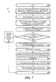
- FIG. 9 is a flow chart illustrating a method for writing data, in accordance with one embodiment of the invention.
- FIG. 10 is a flow chart of a method for reading data, in accordance with one embodiment of the invention.
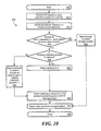
- FIG. 11A is first part of a flow chart of a method for garbage collection, in accordance with one embodiment the invention.
- FIG. 11B is a second part of the flowchart of FIG. 11A , in accordance with one embodiment of the invention.
- FIG. 11C is a third part of the flow chart of FIG. 11A , in accordance with one embodiment of the invention.
- the present invention can be implemented in numerous ways, including as a process, an apparatus, a system, or a computer readable medium such as a computer readable storage medium or a computer network wherein program instructions are sent over optical or electronic communication links and stored at and executed on a computer system.
- the methods and apparatus of at least some embodiments of the invention may take the form, at least partially, of program code (i.e., instructions), such as a software application, embodied in tangible computer readable program media (also known in the art as machine readable program media and computer-usable storage media), such as floppy diskettes, CD-ROMs, hard drives, universal serial bus (USB) memory devices, memory cards, random access or read-only memory, or any other tangible or physical machine-readable storage medium, wherein the program code can be executed by the processor of a computer system to implement any of the processes or methods described herein.
- program code i.e., instructions
- a software application embodied in tangible computer readable program media
- tangible computer readable program media also known in the art as machine readable program media and computer-usable storage media
- the program code can be executed by the processor of a computer system to implement any of the processes or methods described herein.
- program code embodied on the computer readable program medium is loaded into and executed by a machine, such as
- the methods and apparatus of the invention also may be embodied in the form of program code that is transmitted over some transmission medium, such as over fiber optics, electrical wiring or cabling, then stored at and executed on a computer system, where the program code combines with the processor to provide a unique apparatus that operates analogously to specific logic circuits.
- the program code (software-based logic) for carrying out the method is embodied as part of the system described below. It should be noted that the order of the steps of disclosed processes may be altered within the scope of the invention.
- FIGS. 1A through 1E each include illustrative block diagrams of respective exemplary computer systems 10 A- 10 E in which at least one embodiment of the present invention can be embodied
- FIG. 2 is an exemplary software architecture in which at least one embodiment of the invention can be embodied.
- FIG. 1A is a first illustrative block diagram of an exemplary computer system 10 A in which at least one embodiment of the present invention can be embodied, in which deduplication-related layers 28 , 31 , 32 , and 44 are implemented on a host 12 and a thin provisioning layer 54 is implemented on a storage appliance 14 .
- deduplication-related layers 28 , 31 , 32 , and 44 are implemented on a host 12
- a thin provisioning layer 54 is implemented on a storage appliance 14 .
- the elements shown in FIGS. 1A-1E are described in greater detail herein.
- FIG. 1B is a second illustrative block diagram of an exemplary computer system 10 B in which at least one embodiment of the present invention can be embodied, in which deduplication-related layers 28 , 31 , 32 , and 44 and the thin provisioning layer 54 are both implemented on a host 12 .
- FIG. 1C is a third illustrative block diagram of an exemplary computer system 10 C in which at least one embodiment of the present invention can be embodied, in which deduplication-related layers 28 , 31 , 32 , and 44 and a thin provisioning layer 54 are implemented on a storage appliance 14 .
- FIG. 1D is a fourth illustrative block diagram of an exemplary computer system 10 D in which at least one embodiment of the present invention can be embodied, in which deduplication-related layers 28 , 31 , 32 , and 44 are implemented on a network switch 19 and thin provisioning layer 54 is implemented on a storage appliance 14 .
- FIG. 1E is a fifth illustrative block diagram of an exemplary computer system 10 E in which at least one embodiment of the present invention can be embodied, in which deduplication related layers 28 , 31 , 32 , and 44 and compression related layers 35 and 45 are implemented on a host 12 and thin provisioning layer 54 is implemented on a storage appliance 14 .
- deduplication (and, where applicable, compression) processes described herein work in substantially the same manner for the embodiments of FIGS. 1A through 1E .
- each of the embodiments of FIGS. 1A through 1E shows a system that uses the space reclamation process of deduplication, whether alone or in combination with the space reclamation process of compression ( FIG. 1E ), those of skill in the art will appreciate that the invention also can be implemented without deduplication (e.g., with only compression).
- I/O input/output
- the deduplication abstraction/mapping layer 32 and/or the compression abstraction/mapping layer 35 prior to going through the thin provisioning layer 54 .
- the actual layers can be implemented anywhere, e.g., all on host 12 ( FIG. 1B ), all on storage appliance 14 (e.g., FIG. 1C ), all on a switch (e.g., FIG. 1D ), etc.
- the I/O path order through the layers that is preserved, in at least one embodiment of the invention, is this order: deduplication block layer 28 , then I/O synchronization layer 31 , then the mapping metadata layers (i.e., deduplication abstraction/mapping layer 32 and (optionally) compression abstraction/mapping layer 35 , where the deduplication abstraction/mapping layer 32 and the compression abstraction/mapping layer 35 could be in either order) then the thin provisioning layer 54 (which has its own metadata).
- other layers can be disposed between any of the layers 28 , 31 , 32 , 35 , and 54 , so long as the I/O path follows that order of layers.
- the host computer 12 (also referred to herein as a general purpose computer 12 ) includes memory 15 , a processor 16 (which can include one or more central processing unit (CPU) chips) and one or more interconnects 18 (e.g., a host bus adapter) that controls communication between the processor 16 and one or more storage appliances 14 via communication bus 17 .
- the memory 15 stores programs and/or data that the processor 16 uses as it executes operations; in addition, as described further herein, the memory 15 also can help to store copies of certain mapping information to make reads and/or writes of deduplicated logical devices more efficient.
- the memory 15 stores copies of the shared bit table 80 A (see shared bit 80 A of FIG. 4A , described further herein) and the shared map 82 A (see shared map 82 A of FIG. 4A ), which are in use during the read and write processes, as explained further herein.
- a data deduplication process (described further herein) runs in the computer system 10 A to reduce redundant data stored in the storage appliance 14 .
- the deduplication process identifies redundant data in the storage capacity and replaces the redundant data with a reference/pointer to a copy of the data that is stored elsewhere in the storage appliance 14 .
- an advantageous mapping solution and corresponding read and write algorithms provided for in at least some embodiments of the invention, help the deduplication process and/or a compression process and input/output (I/O), including reads and writes, to be more efficient than known deduplication and/or compression processes.
- the allocation features of virtual provisioning are used to help reclaim space (referred to herein as chunks that have undergone data reduction or space saving processes, or alternatively as so-called “unneeded chunks”), where the space (e.g., the chunk) has been identified using the data reduction and space saving methods (e.g., deduplication, garbage collection, and compression) discussed herein.
- deduplication the chunk is unneeded because the data is shared and stored elsewhere; in the case of compression, the chunk is unneeded because the data has been compressed and stored elsewhere.
- an unneeded chunk is a physical chunk that is no longer needed for data storage, and thus can be returned to the pool of data storage for re-use.
- the computer system 10 A can include any devices useful for providing the described functions, including well-known data processing and storage and communication devices and systems such as computer devices and/or systems used as hosts in user systems with processing, memory, and input/output components, and server devices configured to maintain and then transmit digital data over a communications network, these devices including but not limited to a personal computer (PC), laptop computer, client, network appliance, storage appliance, server, workstation, personal digital assistant (PDA), mobile communications device (including so-called “smart phones”), an interconnected group of general purpose computers, host computer systems, enterprise computer system, Ethernet networks, intelligent switches running in a SAN or in a Fibre channel or Ethernet Network, etc., running any one of a variety of operating systems.
- PC personal computer
- PDA personal digital assistant
- mobile communications device including so-called “smart phones”
- the computer system 10 A can be implemented as part of a storage area network (SAN) environment, where the SAN itself may include thousands of different inter-related logical and physical entities.
- SAN storage area network
- these entities which comprise the connections between hosts 12 and storage appliances 14 , may include Fibre Channel host bus adapters, Fibre Channel switches, Fibre Channel routers, a network switch, and the like; an example of this type of environment is illustrated in FIG. 1D herein.
- the general purpose computer system 10 advantageously includes and/or is capable of communicating with network and/or storage appliances, devices or systems (including enterprise storage systems, remote storage systems, intelligent storage systems, disaster recovery systems, etc.) that store data and/or computer programs used by the general purpose computer system.
- Data typically is communicated in digital format following standard communication and transfer protocols.
- the data storage resources also referred to as storage appliances, are generally described as disk, flash, optical, and tape devices that implement RAID and other storage techniques and that may use SCSI and other I/O, data transfer, and storage protocols, but the invention is not intended to be limited to the example embodiments or to specific hardware and storage mechanisms as it is useful for nearly any computer environment.
- the computer system 10 includes a memory 15 (e.g., random access memory (RAM)) and a processor 16 (also referred to as a central processing unit (CPU)), which can be any type of microprocessor.
- a memory 15 e.g., random access memory (RAM)
- a processor 16 also referred to as a central processing unit (CPU)
- CPU central processing unit
- I/O controller such as an input/output (I/O) controller, a network interface, a display device, one or more input devices, and, optionally, one or more removable storage devices, including but not limited to a CD/DVD drive unit, a floppy disk drive unit, a tape drive unit, a PCMCIA or other card drive, a USB-based flash drive unit, and the like, and a data bus coupling these components to allow communication therebetween.
- I/O controller such as an input/output (I/O) controller, a network interface, a display device, one or more input devices, and, optionally, one or more removable storage devices, including but not limited to a CD/DVD drive unit, a floppy disk drive unit, a tape drive unit, a PCMCIA or other card drive, a USB-based flash drive unit, and the like, and a data bus coupling these components to allow communication therebetween.
- one or more computer programs define the operational capabilities of the computer system 12 .
- Operating systems usable with at least some embodiments of the invention include (but are not limited to) systems available from Sun Microsystems, and running the Solaris operating system (a version of Unix); HP-UX (a Hewlett-Packard operating system, running a Hewlett-Packard version of the Unix operating system), available from Hewlett-Packard Corporation; AIX (an IBM version of Unix), available from IBM Corporation; hypervisors such as Hyper-V (available from Microsoft Corporation) and/or ESX and ESXI (available from VMware), and/or any other operating system such as LINUX, or the WINDOWS family of operating systems (available from Microsoft Corporation).
- programs can be loaded into the computer system 10 in many ways, including but not limited to a hard disk drive, a CD/DVD drive, and a network interface.
- the programs can reside in a permanent memory portion (e.g., a read-only-memory (ROM)) chip) of the main computer system 12 memory.
- ROM read-only-memory
- the computer system 12 can include specially designed, dedicated, hard-wired electronic circuits that perform some or all of functions described herein without the need for instructions from computer programs.
- An exemplary storage area network provides a communication infrastructure, including physical connections between computer systems, storage devices, and a management layer, which organizes the connections, storage devices, and computer systems.
- SANs storage area networks
- data storage systems such as the Symmetrix Integrated Cache Disk Array System, the CLARiiON Disk Array System, and/or the Celerra family of storage systems, all of which are available from EMC Corporation of Hopkinton, Mass., as well products provided by vendors other than EMC Corporation, especially SANs having disk arrays where thin provisioning can be implemented.
- Such data storage device systems and their implementation are fully described in many publicly available documents from EMC Corporation, as well as in U.S. Pat. No. 6,101,497 issued Aug. 8, 2000, and also in U.S. Pat. No. 5,206,939 issued Apr. 27, 1993, each of which is assigned to EMC (the assignee of this invention) and each of which is hereby incorporated by reference. Consequently, the discussion herein makes only general references to the operation of such systems.
- the operating system 22 includes several components presented in FIG. 1 as layers, including a file system 24 , logical volume manager (LVM) 26 and block device interface 42 .
- the block device interface 42 can include elements known in the art, such as host bus adapter (HBA) drivers, and the like.
- the deduplication block layer 28 manages one or more virtualized LUNs 30 (vLUN 30 ), that are presented by the I/O filter driver 72 (not illustrated in FIG. 1A , but shown in the software architecture of FIG. 2 ) to the layers above it, such as the LVM 26 , file system 24 , and applications 20 .
- an application 20 When an application 20 is reading or writing data, it communicates (i.e., reads and writes) with one or more vLUNs 30 .
- the I/O filter driver 72 FIG. 2 containing deduplication I/O block manager 91 , filters those reads/writes and layers 28 and 32 are used to transform them by performing the steps described in the methods of the invention described herein. That is, the vLUN 30 is a logical representation of the mapped LUN 52 as seen by entities above the I/O filter driver 72 .
- the vLUN 30 helps to manage access to and virtualize some or all of the storage capacity presented by the storage appliance 14 (and/or optionally other storage appliances 14 , not shown).
- the mapped LUN 52 is used by the I/O filter driver 72 in the same manner as any other logical unit, but the mapped LUN 52 actually is hidden from layers above the I/O filter driver 72 ( FIG. 2 ), because the I/O filter driver 72 presents the vLUN 30 to these layers, as is well understood in the art.
- the vLUN 30 can be used for raw access, file systems can be mounted on it, and it can be placed under control of the LVM 26 .
- the mapped LUN 52 and its virtual provisioning are described further below.
- the communications bus 17 can include any of a number of different types of communication links, with the interconnect 18 and storage appliance interface 50 being adapted to communicate using an appropriate protocol via the communication buses 17 coupled there between.
- the communication bus can be implemented as a small computer system interface (SCSI) bus, an Internet-SCSI (iSCSI) bus, a Fibre Channel fabric, or Fibre Channel over Ethernet (FCoE).
- SCSI small computer system interface
- iSCSI Internet-SCSI
- FCoE Fibre Channel over Ethernet
- the communications bus 17 is not required, especially if the space reclamation layers 29 , 31 , 32 (and/or optionally 35 —see FIG. 1E ) and the thin provisioning layer 54 are physically part of the same device, apparatus or machine.
- the storage appliance 14 can include any type of persistent storage, such as hard disks (e.g., any Fibre Channel or SATA disk drive) and/or Enterprise Flash Drives (EFD) where copies of data (e.g., files, executables and the like), are stored. The copies of data can be primary copies or duplicate (e.g., backup) copies.
- the storage appliance 14 (which can include logical units (LUNS), such as the mapped LUN 52 , explained further below) makes storage resources available to the host computer 12 for assignment to entities therein, such as the file system 24 , the logical volume manager 26 , an I/O filter subsystem 67 with I/O filter driver 72 (see FIG. 2 ), and a block device interface 42 .
- LUNS logical units
- storage appliance 14 includes a storage appliance interface 50 that interfaces to the host computer 12 via the communications bus 17 .
- the block device interface/access layer 58 links all block devices to look like an array of blocks and performs, if applicable, all RAID functions.
- the storage appliance 14 also includes one or more disk drives 60 A, 60 B, 60 C, 60 D. If there is more than one disk drive, e.g., multiple disk drives 60 A, 60 B, 60 C, 60 D, the multiple disk drives 60 A- 60 D can combine to form a pool 60 of disk drives.
- the pool 60 of disk drives can, in some embodiments, be grouped into an array, but this is not required.
- the thin provisioning layer 54 allocates chunks to the mapped LUN 52 as needed (i.e., when they are written to) and the thin provisioning layer 54 gets the needed chunks from the pool 60 .
- a typical disk pool 60 can, of course, include elements not illustrated in FIG. 1 a , but well known to those of skill in the art, such as a disk array controller, a cache, disk enclosures, and a power supply.
- the storage appliance 14 includes a construct called a mapped LUN 52 that is implemented using the thin provisioning layer 54 (thin provisioning is sometimes referred to in the art as virtual provisioning).
- the mapped LUN 52 interfaces between the host 12 and the pool 60 to create, via thin provisioning layer 54 , a mapping between the mapped LUN 52 (which can be thought of as an array of chunks) and the actual location of each chunk on the disk drives in the pool 60 .
- the vLUN 30 creates a second mapping between the array of chunks presented by the vLUN 30 and the storage provided by the mapped LUN 52 .
- the array of chunks presented by the vLUN 30 to an application 20 presents more storage to the application 20 than is actually physically allocated (assigned) to the vLUN 30 by the storage pool 60 at a given time, where actual physical storage is allocated to vLUN 30 for use by the application 20 from the pool 60 only when the (additional) storage actually is written to by the application 20 .
- the thin provisioning layer 54 allocates storage from the pool 60 in allocation units, which also are known in the art as data storage extents, or, simply storage extents. Each data storage extent has a predetermined size and corresponds to the minimum quantum of storage allocated at a time from the pool 60 . Exemplary sizes of data storage extents used in at least some embodiments of the application include sizes such as 4 KB, 8 KB, and 16 KB, but these sizes are not limiting. The size of the data storage extent is implementation dependent, as understood by those of skill in the art, and may vary based on the type of storage system used and/or type of disk drive in the pool 60 .
- the mapped LUN 52 With thin provisioning, the mapped LUN 52 actually reserves fewer than the maximum number of data storage extents specified by an application, without the application 20 being aware of this thin provisioning. In the event that an application 20 actually desires to write to more space than was thinly provisioned for the mapped LUN 52 , extra data storage extents may be allocated from the pool 60 (if any exist). Further, the size of the pool 60 can be non-disruptively and dynamically increased (e.g., automatically, by policy) by adding additional disks to the pool 60 .
- the mapped LUN 52 also can include data structure and storage extent pointer manipulation capabilities for managing the allocated data storage extents.
- the thin provisioning layer 54 includes a mapping software functionality that provides a mapping service to optimize the placement and use of physical storage used by a mapped LUN 52 having thin provisioning 54 .
- the host computer 12 further includes a deduplication engine 44
- the operating system 22 further includes a deduplication block layer 28 (which provides the vLUN 30 ) and a deduplication abstraction/mapping layer 32 (which includes a map 34 , described further herein).
- the deduplication block layer 28 can be managing one or more vLUNs 30 .
- the deduplication engine 44 communicates with the operating system 22 (in particular, with the deduplication block layer 28 ).
- the deduplication engine 44 provides block-level deduplication services for the host computer 12 , and performs deduplication on chunks of the data addressed by or referenced by the deduplication block layer 28 ; that is, the deduplication engine 44 performs deduplication on data stored by the vLUN 30 managed by the deduplication block layer 28 .
- the deduplication engine 44 is part of a data reduction engine 46 , where the data reduction engine also includes a compression engine 45 operable to perform data compression on a deduplication block device managed by the deduplication block layer 28 ; the deduplication block layer 28 and data reduction engine 46 together form a deduplication, compression, and garbage collection layer 29 ′.
- the data reduction engine 46 includes only the compression engine 45 and not the deduplication engine 44 , although this specific embodiment is not illustrated in the Figures.
- data reduction engine is not intended to require only processes where the data being stored is necessarily physically compacted or reduced in size, as is the case with compression. Rather, the term “data reduction engine” encompasses any processes that result in a reduced use of physical storage required to store data.
- deduplication as described herein, is considered a type of data reduction process, because deduplication can (if duplicates are found) result in reduction of the number of copies of data stored in physical storage, thus resulting in reduced use of physical storage required to store the same data.
- data reduction process is not limited to processes that physically reduce or compact data, but is intended to encompass any process that has an end result of reducing the amount of physical storage required to store data.
- the data reduction chunk size (that is, the quantity of data that is deduplicated or compressed at a time) also is referred to herein as the size of the deduplication chunk, or size of the compressed chunk, or, generically, the size of the unneeded chunk.
- the size of this unneeded chunk is defined as being a size X, where X advantageously is a nonzero integer multiple of the size of the data storage extent (allocation unit) of the thin provisioning layer 54 , as is explained further below.
- the compression has to compress a nonzero integer multiple of the storage extent size into a smaller nonzero integer multiple of the storage extent size.
- the compression layer saves space by “packing” multiples of compressed chunks into a single chunk. For example, assume that compression starts with first compressing a chunk of size 4 ⁇ , and the resultant compressed chunk had a size of 1.5 ⁇ . Another chunk of size 4 ⁇ is compressed to a chunk of size 2.5 ⁇ . The two compressed chunks (the 1.5 ⁇ chunk and the 2.5 ⁇ chunk) are stored together in a single chunk of size 4 ⁇ , thereby saving a 4 ⁇ of space.
- This “packing” of compressed chunks together can, in one embodiment, use a variation of the metadata mapping for compression shown in FIG. 4B (which is an illustration showing in greater detail the metadata portion of the mapping layout of FIG.
- the compressed metadata map 82 B is adapted to provide information relating to the packing, in addition to the other information (the metadata map 82 B is described further herein).
- the information relating to the packing in one embodiment, varies from the metadata layout 34 B for compression of FIG. 3B in that the compressed metadata map 82 B uses offsets into the compressed region 38 B, instead of a logical chunk address (LCA).
- LCA logical chunk address
- the deduplication engine 44 (and/or, in one embodiment, the compression engine 45 or data reduction engine 46 ) effectively communicates with the mapped LUN 52 of the storage appliance 14 via the I/O filter driver 72 , which includes its own logical representation of the deduplication block layer 28 , namely, the deduplication I/O block manager 91 .
- the deduplication engine 44 is illustrated as part of a deduplication and garbage collection layer 29 that is operating on the host computer 12 .
- FIG. 1A the deduplication engine 44 is illustrated as part of a deduplication and garbage collection layer 29 that is operating on the host computer 12 .
- the data reduction engine 46 (which includes both a deduplication engine 44 and a compression engine 45 ) is illustrated as part of a deduplication, compression, and garbage collection layer 29 ′ that is operating on the host computer.
- the deduplication engine 44 (or compression engine 45 , or data reduction engine 46 ) also can also be installed in the storage appliance 14 (as shown in FIG. 1C ), or in a switch (as shown in FIG. 1D ) or even at a remote client or server (not shown, but well understood by those of skill in the art in connection with FIGS. 1A-1E ), so long as the deduplication engine 44 is in operable communication with the rest of the deduplication and garbage collection layer 29 , including the chunks of data that are being deduplicated.
- the deduplication engine 44 can be located anywhere where it can operate on the chunks of data being deduplicated, even without the presence of either the host computer 12 or the storage appliance 14 (that is, the space reclamation processes described herein can be implemented on a single platform, without a host or an array), so long as the deduplication engine coordinates through synchronization with the aforementioned I/O path (e.g., is processed in the order described above; namely, the deduplication block layer 28 , then the I/O synchronization layer 31 , then the mapping layers (e.g., deduplication abstraction/mapping layer 32 and/or compression abstraction/mapping layer 35 , in either order), then the thin provisioning layer 54 , with other layers permitted between any of these aforementioned layers permitted so long as this order is maintained.
- the mapping layers e.g., deduplication abstraction/mapping layer 32 and/or compression abstraction/mapping layer 35 , in either order
- deduplication engine 44 can be installed is equally applicable to the data reduction engine 46 and/or the compression engine 45 , as will be appreciated by those of skill in the art, so long as the synchronization with the I/O path through layer 92 ( FIG. 2 ) is maintained.
- the deduplication engine 44 cooperates with the garbage collection process (described further herein in connection with FIGS. 11A , 11 B and 11 C) and/or the allocation mechanism provided with thin provisioning 54 to perform block-level deduplication on chunks stored in vLUN 30 , and thus effectively processes data that physically is stored in storage appliance 14 , to identify and reduce duplicative/redundant data and reclaim the space.
- the deduplication engine 44 can implement virtually any deduplication algorithm configured to identify redundant data and replace the redundant data with a reference to a single instance of the data, where, in at least some of the embodiments of the invention described herein, metadata is used to locate the single instance of the data (via the shared map, described further herein).
- a data object which may be a file, a block, a data stream, or some other form of data, is broken down into one or more chunks.
- the chunk size for the deduplication engine 44 (also referred to herein as the data reduction chunk size, deduplication chunk size, compression chunk size, or unneeded chunk size) is sized so that it is a nonzero integer multiple of the size of a data storage extent used with thin provisioning.
- the invention is using a thin provisioning configuration that employs two different levels of allocation. In this configuration, storage is allocated out of the pool 60 in large extents, but storage provided to be used for writing data is allocated in very small extents.
- the chunk size is a nonzero integer multiple of the size of the smaller extent size used for writing data.
- the deduplication block layer 28 has reduced complexity and does not need to include or provide its own mapping and allocation mechanisms; instead the deduplication block layer 28 leverages the mechanism to do this that is already provided by a thin provisioning layer 54 that can be directed to release one or more data storage extents. If the nonzero integer multiple is greater than one, the virtual provisioning layer 54 can simply be directed to release that multiple of data storage extents.
- each chunk of data is processed using a hash algorithm, such as the Message Digest Algorithm (MD5), officially defined by RFC1321 by the Massachusetts Institute of Technology (MIT) Laboratory for Computer Science, or an algorithm in the Secured Hash Algorithm (SHA) family, such as SHA-1, where the SHA family is designated by the National Security Agency in FIPS-180-1.
- MD5 Message Digest Algorithm
- SHA-1 Secured Hash Algorithm
- This hash algorithm process generates an identifier, referred to as a fingerprint, digest, or hash, for each chunk, which is based at least in part on the contents of the chunk, where two chunks with identical contents will produce the same fingerprint.
- the digest is then stored in an index, which facilitates comparison of all of the digests, to search for duplicate digests.
- Duplicate digests generally indicate that the data chunks are identical, and can thus be subject to deduplication. In some instances, however, duplicate digests can indicate a so-called “hash collision,” (which occurs when different chunks produce the same hash). In some instances, hash collisions can occur if the hash algorithm, used to generate the respective digests, is not strong enough.
- the contents of the corresponding chunks are compared to confirm that the two chunks, are, in fact, the same, before the chunks are shared (i.e., before finally concluding that two data chunks are identical and can be subject to deduplication).
- the deduplication engine will treat the chunk associated with the given digest as a unique chunk with no duplicates already in storage. If, however, a match is found for a given digest, the chunk associated with the given digest is treated as being non-unique, because a duplicate exists.
- the duplicate chunk instead is referenced by storing the location of its data in an entry in the shared map 82 A ( FIG. 4A ).
- the determination of whether a chunk has a duplicate is done as the data is being written.
- the deduplication engine 44 performs the deduplication in an “out of band” or “post process” or “background” manner—that is, the deduplication engine 44 identifies and replaces redundant data with pointers after the data has already been written into storage.
- the deduplication engine 44 can scan the direct region ( 36 A) of mapped LUN 52 to search for two direct chunks that have the same digest (and thus are likely to be duplicates), and then write out metadata in the shared map 82 A and shared bit map 80 A (see FIGS. 3A and 4A ) to indicate that the data formerly stored in the two direct chunks (that were found to be duplicates) is now stored in the shared region 38 A.
- the deduplication engine 44 operates using a fixed-chunk size, the fixed-chunk size being at least partially dependent on the data and type of application.
- the invention can be adapted in other embodiments to operate using a variable chunk size.
- Variable length chunk sizes can, in some instances, result in more complicated mappings and remappings than with fixed chunks; however, variable length chunk sizes are more readily implemented if the space reclamation-related layers 28 , 31 , 32 , and/or optionally 35 , and the thin provisioning layer 54 , are all provided/implemented entirely within a storage appliance 14 , as is illustrated in FIG. 1C .
- the thin provisioning layer 54 can even provide data storage extents of a variable size.
- the deduplication engine 44 when the deduplication engine 44 has found redundant space and garbage collection has cleaned it of excess states and settings, it is efficient for the reclaimed physical chunks of space (i.e., the chunks of space that used to be occupied by the deduplicated chunks and/or compressed chunks (each of which also is referred to herein as unneeded chunks)) to be provided back to the logical unit (mapped LUN 52 ) via the same process that thin provisioning uses to release data storage extents no longer used by applications 20 .
- This process for providing reclaimed chunks of space back to the logical unit is equally applicable when other data reduction processes, such as compression, are complete, as well. This is explained further herein.
- FIG. 3A is an illustration of a deduplication mapping layout for information stored on a virtual logic unit, for the computer system of FIG. 1A , in accordance with one embodiment of the invention.
- FIG. 3B is an illustration of a compression mapping layout for information stored on a virtual logic unit, for the computer system of FIG. 1E , in accordance with one embodiment of the invention. Compression's use of this mapping layout is discussed later herein.
- FIG. 4A is an illustration showing in greater detail a metadata portion 40 of the mapping layout 34 of FIG. 3A .
- the layout 34 A defines the mapping used by the deduplication block layer 28 to store the logical data of vLUN 30 onto the physical mapped LUN 52 , where the deduplication block layer 28 implements the mapping and read/write code and where the vLUN 30 presents a logical device to applications.
- the layout 34 A shows the layout of mapped LUN 52 as divided into three regions, including a direct region 36 A, a shared region 38 A, and a metadata (MD) region 40 A.
- the deduplication block layer 28 configures mapped LUN 52 to have a total of M chunks, where M is a number that is greater than the size of the vLUN 30 (note that the size of the vLUN 30 , N, corresponds to the size of the direct region 36 A in the layout 34 A of FIG. 3A ). Note also that there can be many instances of vLUN 30 , each with its own instance of mapped LUN 52 .
- M (3 N/ 2)+ Z (1)
- the total number of chunks L for the compression layout 34 B need not be the same total number as the number M shown for deduplication in FIG. 34A , nor are any of the other same requirements of Equation (1) above necessarily applicable to or required for the total number of compression chunks.
- M represents the total number of chunks of a predetermined size X that are contained in the thinly provisioned mapped LUN 52 .
- the chunk size X advantageously is a nonzero integer multiple of the size of data storage extent used with the thinly provisioned mapped LUN 52 .
- the chunk size X can be virtually any size, including having the same size as that of the data storage extent (i.e., a multiple of one (1)).
- the chunk size X is selected so that it is not smaller than the size of the thin provisioning allocation unit.
- the size of the vLUN 30 as exposed to the application 20 (and file system 24 and LVM 36 ) is N*X bytes (where X is the size of the chunk in bytes).
- the shared region 38 A having a size of K chunks of X bytes each, is never exposed to the application 20 , file system 24 , or LVM 36 .
- the M chunks are the total number of chunks that are mapped to the mapped LUN 52 .
- the size of the metadata region is 1 GB.
- the chunk size X is a nonzero integer multiple of the size of the data storage extent, and assume that this nonzero integer multiple is one (1).
- Those of skill in the art can similarly convert the direct region 36 A, shared region 38 A and MD region 40 A to chunks.
- the vLUN 30 provides a total of N logical chunks (e.g., from 0 to N ⁇ 1), addressed by logical chunk address (LCA). To every layer above the vLUN 30 , the LCA looks like any other address. As is explained herein and as is illustrated in FIGS. 3A and 4A , the bitmap (a collection of multiple bits) of the mapping layout 34 A has a bit for each LCA in the shared bit table 80 A.
- the direct region 36 has physical chunk addresses (PCAs) that are denoted dPCAs, with the “d” indicating that the chunk addresses are in the direct region 36 A.
- PCAs physical chunk addresses
- the LCA is the same as the dPCA; thus, for data stored in the direct region 36 A, there is no need for a shared map entry in the metadata regions 40 A that shows for an LCA where its shared physical chunk address (sPCA) is.
- the vLUN 30 is used to present to applications 20 a logical storage area having a size of N chunks.
- the deduplication block layer 28 uses the layout 34 A of the deduplication abstraction/mapping layer 32 and the metadata stored in region 40 A to map the LCA to the location where the data is stored, which can be in either the direct or shared region, depending on the setting of shared bit 80 A.
- the shared bit 80 A can have a value of zero (not shared) or one (shared).
- the shared bit 80 A is set to one, there's a corresponding entry in the shared map 82 A showing the corresponding shared physical chunk address (sPCA) location for that LCA.
- the shared bit 80 A is a shared bit table, where there is a bit for each logical chunk address (LCA), and a map entry (in the shared bit map 82 A) for each LCA that is shared.
- the functions of the shared bit 80 A can be implemented using any arrangement capable of indicating whether or not there is a corresponding entry in the shared map that shares a corresponding sPCA.
- the layout 34 A of the deduplication abstraction layer 32 further defines a shared region 38 A for storing shared chunks, where the shared chunks 38 A are in use only after deduplication processing detects that one or more chunks are duplicates of each other (i.e., the shared chunks 38 A exist, but, because of the thin provisioning 54 , are not yet allocated, so no physical space is yet used for the shared chunks until deduplication has occurred and has found at least one pair of chunks having the same digest and the same data).
- the applications 20 are not aware of the existence of the K chunks in shared region 38 A. Rather, the applications 20 only can access data by LCA (that is, the direct region 36 A).
- the deduplication block layer 28 does a mapping to the correct location.
- an application 20 asks to access a given LCA of vLUN 30 .
- the I/O filter driver 72 maps that application 20 's request to the appropriate PCA within mapped LUN 52 . If the chunk is not shared, then the PCA (dPCA) for that chunk is the same as the LCA. If the chunk is shared, as indicated by the shared bit 80 A being set in the metadata 40 A ( FIG. 4A ), then the shared map 82 A tells the layer 28 which PCA (sPCA) to use to access the data. Whether the LCA is shared or not is denoted by its bit in the Bit Table ( 80 A). One job of the deduplication block layer 28 is to translate the I/O request from above it into the correct location(s) and pass this down the I/O stack.
- the physical addresses within the mapped LUN 52 for these shared chunks in the deduplication block device (sPCA) go from chunk N to chunk (N+K) ⁇ 1, where K ⁇ M, as well.
- the layout 34 A is a logical representation, not a physical representation, and the shared region 38 A need not be physically adjacent to the direct region 36 A).
- K ⁇ N ⁇ M K generally is less than N (i.e., the shared region 38 A is smaller than the direct region 36 A).
- N is the number of chunks presented by vLUN 30 .
- the size of the shared region 38 A is N/2. This size is not limiting on the embodiments of the invention, however.
- the shared region 38 A can have other sizes, including sizes smaller than N/2. However, if the shared region 38 A is smaller than N/2, it is possible to have duplicated chunks that can't be shared.
- the shared region 38 A is configured in accordance with a data structure (which can be stored in the metadata region 40 A on the mapped LUN 52 ).
- the metadata region 40 A for the implementation of the vLUN 30 having the layout 34 A includes, in one embodiment, an array indexed by LCA that contains an entry of a predetermined size for the physical chunk address (PCA) (the PCA is the actual location of the data, and the entry points to the location within the shared region 38 A of the mapped LUN 52 where the data for that particular LCA actually is stored).
- PCA physical chunk address
- Other types of data structures besides arrays are, of course, usable.
- each shared map entry 82 A contains a PCA.
- the size of the entry for the PCA is 64 bits (8 bytes), but this is not limiting.
- Each chunk in the shared map 82 A contains a predetermined number of entries. In one embodiment, the predetermined number is dependent on the size of the chunk itself and the size of the entry, but this is not limiting.
- the metadata 40 A/ 40 B i.e., the content
- the metadata could instead provide information in the form of offsets.
- the layout 34 A also includes a metadata (MD) region 40 A, having a size of Z chunks.
- Z has a size that is sufficient to hold all the metadata needed for vLUN 30 , using the layout 34 A.
- the size Z will be a small percentage of the size K of the shared region, but this is not limiting.
- the MD 40 A consists of three parts.
- the first part includes a shared bit 80 A for each chunk in the vLUN 30 presented to users (e.g., applications 20 ), where the shared bit 80 A is set if the chunk is shared.
- the second part includes a shared map 82 A, where the shared map 82 A has an entry for each shared chunk that points to where it actually is stored. There is a shared bit 80 A for every logical chunk, but there may be a shared map for only the shared logical chunks. For example, if the shared map 82 A is stored as an entry in an array, then there could be an entry for every logical chunk, and the ones that are not shared would not be used, such that the PCA would be set to NULL. Note also that it is not required for all the shared bits to be physically placed together.
- the shared map 82 A portion of the metadata 40 A is always loaded in memory 15 or other fast media (i.e., always available and stored in the deduplication block layer 28 ); this helps to improve the efficiency of reads and writes by applications 20 .
- the shared bits 80 A can be physically placed together, in a tightly packed area, to further help improve efficiency during reads and writes (as will be discussed further herein), but the shared bits 80 A are not required to be physically proximate to the other parts of the metadata 40 A.
- the third part of the MD 40 A includes a digest 84 A, where the digest 84 A is a simple byte array, indexed by sPCA, of unique identifiers (e.g., fingerprint or hash of each share chunk) for a chunk of data.
- the deduplication engine 44 uses the digest 84 A to help locate potential matches to a given chunk and to find shared chunks that have previously been deduplicated.
- the digest 84 A includes only digests of shared chunks.
- the digest 84 A includes not only digests of shared chunks, but also digests of direct chunks that are in the process of being checked during deduplication (e.g., to be compared to other direct chunks, as is described later in connection with process of FIG. 8 ).
- the shared bit 80 A is configured using a data structure indexed by LCA and containing a bit, such as: SharedBitMap[LCA].bit (3)
- the associated LCA is associated with data stored in the shared region 38 A; else, the associated LCA is associated with data stored in the direct region 36 A.
- the digest 84 A is a byte array to identifiers for a chunk of data.
- the digest data is computed/derived (e.g., by using the aforementioned hash algorithms) from the data in the chunk.
- mapping arrangement 34 A keeps the direct region 36 A, as a “pure” direct region 36 (i.e., by “pure,” it is meant that the I/O filter driver 72 ( FIG.
- mapping layout 34 A and write and read methods described herein can help to reduce overhead for reads and writes done after deduplication, as described further below.
- any writes from an application 20 always go into the direct region 36 of N chunks, by way of the I/O filter driver 72 , without having to check a map to locate unused free space and without having to specifically allocate any other free location in which the write is to be stored, as might be required to be done in other deduplication arrangements.
- inventive mapping layout 34 A and read method FIGS. 3 , 4 , and 9
- a read will either have essentially zero overhead (for non-shared chunks) or, for shared chunks, an overhead equal to the cost of reading the mapping metadata for the chunk.
- the shared map 82 A is in memory 15 or fast media, and doesn't have to be read, then the overhead for reading the mapping metadata is less than the added overhead of having to read each pointer to a shared chunk, then further having to read that chunk. Because there are many more entries on a chunk in the shared map 82 A, one read of that chunk can be amortized across many data reads.
- FIG. 2 which has been referenced already in the above description, is an exemplary software architecture in which at least one embodiment of the invention can be embodied.
- user I/O calls 57 to the storage system 66 first go through an I/O subsystem 67 in the kernel space 58 , which I/O subsystem includes an I/O filter driver 72 .
- this I/O path for the I/O calls 57 is separate from the processes that are responsible for deduplication.
- the kernel space 58 provides abstraction layers for hardware, memory, processors, and input/output (I/O) and makes these tools available to the user space 56 through system calls.
- the I/O filter subsystem 67 includes an I/O filter driver 72 , which facilitates the sending of I/O requests from applications 20 running on the computer system 12 to the storage appliance 14 .
- the I/O filter driver 72 queues I/O requests from the computer system 12 directed to storage appliance 14 .
- the I/O filter driver 72 implements algorithms to decide which I/O requests to send, how many I/O requests to send, and the speed at which to send I/O requests.
- the I/O filter driver 72 in some embodiments, keeps a record of I/O requests that are sent to the storage appliance 14 until the I/O request is processed by the storage appliance 14 .
- An exemplary host-based I/O filter subsystem 67 that includes an I/O filter driver 72 is the POWERPATH product, available from EMC Corporation.
- the I/O filter driver 72 has a so-called “C-clamp” structure, including an O/S interface 97 along the top, a set of common API's 98 along the left side, and a host bus interface 99 along the bottom, with a plurality of managers 91 , 92 , 93 , 95 coupled to the C-clamp structure via a plurality of general purpose extensions 89 .
- the managers 91 , 92 , 93 , 95 and extensions 89 help implement some of the functions described herein and help to manage I/O for the deduplication block layer 28 (including any associated vLUNs 30 implemented on mapped LUN 52 .)
- the I/O filter driver 72 is responsible for correctly mapping application I/O calls to/from LCAs to the right PCA for each operation and also is responsible for maintaining the metadata kept on the deduplication block layer 28 .
- the I/O filter driver 72 provides synchronization methods used by the deduplication and garbage collection processes described further herein. These functions are, in one embodiment, implemented as extensions within the I/O filter driver 72 , with each extension managing corresponding layers in the system of FIGS. 1A-1E .
- the deduplication I/O block manager 91 manages the deduplication and garbage collection layer 29 (which includes the deduplication block layer 28 and the deduplication engine 33 ).
- the I/O synchronization manager 92 of FIG. 2 manages the I/O synchronization layer 31 , helps synchronize I/O from an application 20 with deduplication operations, and makes sure that the metadata used by each component is kept up-to-date and correct.
- the deduplication mapping metadata manager 92 manages the deduplication abstraction/mapping layer 32 . If the embodiment uses compression (e.g., FIG. 1E ), then the I/O filter driver 72 includes a compression mapping metadata manager 95 to manage the compression abstraction/mapping layer 35 .
- the I/O filter driver 72 may include other I/O filter driver extensions 94 (e.g., extensions that encrypt data, extensions that migrate data, extensions that replicate data, etc.), where these other extensions and managers 94 can be located anywhere (that this, they could be above, below or intermingled with the extensions/managers 91 , 92 , 93 , 95 that embody at least some embodiments of this invention).
- I/O filter driver extensions 94 e.g., extensions that encrypt data, extensions that migrate data, extensions that replicate data, etc.
- a deduplication daemon 68 runs in user space 56 , where the deduplication daemon 68 includes a deduplication engine 44 , a garbage collection module 70 , and a deduplication index 71 .
- the deduplication daemon 68 is a process (which can be scheduled and/or run periodically) that keeps an index of hashes and locations (deduplication index 71 ).
- the deduplication daemon 68 via deduplication engine 44 , is the component that “finds” which chunks have the same data, and then cooperates with the I/O filter driver 72 to direct the rest of the system 10 A to actually share the chunks.
- the deduplication engine 44 performs deduplication.
- the garbage collection module 70 runs an algorithm to clean up leftover state from a successful or unsuccessful write and also cleans up other states that can arise in the functioning of the system 10 A (garbage collection is explained more fully herein). In at least some embodiments of the invention, it is more advantageous to use a lower-priority “outside” process like garbage collection 70 to do such cleanup than having this cleanup done during the course of processing application I/O's, because the outside process of garbage collection, as described herein, has less impact on applications 20 that are running.
- the index 71 is a data structure that stores the digests, which each contain location mapping, as described herein.
- the I/O filter driver 72 via its deduplication I/O block manager 92 , I/O synchronization manager 92 , and mapping metadata managers 93 (and, optionally, 95 ), is the interface that the deduplication daemon 68 uses to make calls to the storage appliance 14 in the storage subsystem 62 that are necessary for deduplication and/or compression.
- a compression daemon 61 runs in user space 56 , where the compression daemon 61 includes a compression engine 45 , a set of compression algorithms 63 , and a compression module 65 .
- the compression daemon 61 via its compression engine 45 , is the component that locates data that are suitable for compression, then uses an algorithm selected from the set of compression algorithms 63 to compress the data, and then cooperates with the I/O filter driver to direct the rest of the system 10 (which could, in this example embodiment, be the system 10 E of FIG. 1E ) to location of the compressed blocks.
- the I/O filter driver 72 when the I/O filter driver 72 is doing a write, the I/O filter driver does the write, then ensures that the shared bit 80 A is cleared (e.g., by clearing it, if necessary), because, in this embodiment, writes are always done to the direct region 36 A, so the shared bit 80 A is not set.
- the process for doing writes in this embodiment is explained more fully herein in connection with the FIG. 9 , which is a method for writing data in accordance with one embodiment of the invention.
- the I/O filter driver 72 needs to look at the shared bit 80 A to see if it is set (e.g., is set to one or is set to be “on”). If the shared bit 80 A is set, then the I/O filter driver 72 uses the share map 82 A to find the correct LCA for the location being read by the application 20 . The I/O filter driver then redirects the read to that location.
- FIG. 5 is a high-level flow chart 100 showing processes that can occur in the system 10 A of FIG. 1A and in the software architecture of FIG. 2 , in accordance with one embodiment of the invention.
- This flow chart describes at a high level the various processes that occur in the system 10 A of FIG. 1 ; the particular details relating to the processes are detailed further herein in FIGS. 6-11B .
- thin provisioning is configured on either the storage appliance 14 or the host computer 12 or network switch 19 (depending on whether the embodiment corresponds to FIGS. 1A , 1 C, 1 D, 1 E or FIG. 1B ), if this has not already been done.
- the direct and shared mapping shown in the map 34 of the deduplication abstraction layer 32 also is established for the given vLUN 30 (or vLUNs 30 , as there can be more than one vLUN 30 ).
- the I/O processes (block 150 ) occurring between the host computer 12 and the storage appliance 14 take place in accordance with the inventive processes described herein. As the flowchart 100 of FIG.
- the I/O processes i.e., read, write
- the processes deduplication, garbage collection, compression
- save and/or reclaim space which are referred to herein, as “space reclamation processes”, “space saving processes”, “data reduction processes,” and/or “storage reduction processes”
- space reclamation processes space saving processes
- data reduction processes data reduction processes
- storage reduction processes storage reduction processes
- the I/O processes and space saving processes can occur in a manner such that one of the processes does not occur until the other one is complete.
- the space saving processes run on the same host computer 12 as the application 20 that is using the vLUN 30 , but this is not required.
- the space-saving processes of FIG. 5 also use the allocation and deallocation features exported by the thin provisioning layer 54 that is implemented using the mapped LUN 52 , as is described herein.
- the application 20 that is using the logical unit undergoing a space saving process could be running on a different host 12 than the space saving process itself, although the actual process that moves the data and reclaims space has to be synchronized with I/O on the host 12 where the application 20 is running.
- deduplication (block 130 ) can run almost anywhere, e.g., on a different host 12 , so long as the deduplication has access to sufficient space to store the deduplication index 71 ( FIG. 2 ) and to interfaces that allow deduplication to get the hashes for the blocks, drive the block sharing, and mark blocks as being shared.
- one or more of the space reclamation processes of FIG. 5 are configured to run at appropriate times in the system 10 , so as not to interfere with the performance of I/O functions of application 20 .
- one or more of the space reclamation processes are configured to run in the background (i.e., “out of band” or “asynchronously”), such that the space reclamation processes are not occurring at substantially the same time as I/O processes, but instead either between, before, or after I/O processes (e.g., during “off hours”, when a given I/O process is complete, and/or before the next I/O process begins).
- the one or more of the space reclamation processes that are running are configured to run at predetermined times, such as at predetermined intervals (advantageously, these intervals are timed so as occur during times of low to no levels of I/O).
- one or more of the space reclamation processes are configured to run as I/O processes occur (e.g., “in band” or “in line”); for example, the deduplication (block 125 ) would be run as data is being written (block 165 ).
- the I/O processes begin (or continue, if they already have been started and/or are in process), including processes such as writing data (block 165 ), which is explained more fully in FIG. 9 , and reading data (block 170 ), which is explained more fully in FIG. 10 .
- the I/O processes continue until complete (block 180 ).
- the space saving processes include block-level deduplication (block 130 ), described further in connection with FIGS. 6-8 ; compression (already well understood in the art and discussed briefly herein) and garbage collection (block 125 ), described more fully in connection with FIGS. 11A-11C .
- the space saving processes beginning at block 120 can be running in-band, at scheduled times, or upon the occurrence of a specific condition.
- the space saving processes beginning at block 120 can provide notification that certain space is no longer needed, and, in one embodiment, the reclamation of the space (i.e., “returning reclaimed blocks/chunks to available storage”) can be implemented as part of any one or more of the space saving processes, as FIG.
- FIG. 5 illustrates, or can be done by a background process, or can be done by some separate process.
- returning the reclaimed space to available storage can occur in many different places, including after all space saving processes are complete and/or after I/O is complete (block 180 ).
- thin provisioning or the alternate mapped LUN 52 ′, or allocate/deallocate processes known to those of skill in the art is used to accomplish the returning/reclaiming of storage space.
- garbage collection is a process that helps to “clean up” leftover state from a successful or unsuccessful write, e.g., cleaning up after a crash (e.g., an unsuccessful write), and moving a chunk back to the direct region 36 A, if it is no longer shared (e.g., after a successful write).
- deduplication (block 130 ) and garbage collection (block 125 ) not run at the same time.
- garbage collection and deduplication are separate processes, and run one after the other, where either garbage collection or deduplication can be first.
- garbage collection and deduplication can be run at the same time (i.e., in parallel), but still as separate processes.
- the deduplication process adds information to the shared map 82 A and effectively moves chunks to the shared region 38 A.
- Garbage collection removes information from the shared map 82 A and, in some instances, may move some shared chunks back to the direct region 36 A.
- compression helps to reduce the size of stored data, by working within a chunk or set of chunks of stored data to identify and remove empty space that appears as repetitive patterns. Compression thus can sometimes be viewed as a form of data deduplication, but the deduplication is local to the chunk itself, and is not used to recognize and eliminate duplicate chunks, although compression can independently compress each of the chunks.
- the compression is done at the block level, where it looks for repetitive patterns within a block. In the example embodiment of FIG.
- the system 10 E includes a data reduction engine 46 , which includes both a deduplication and garbage collection engine 44 and a compression engine 45 , indicating that both space saving processes are being run.
- the data reduction engine 46 implements one or the other of data reduction and compression, but not both.
- FIG. 3B is an illustration of a compression mapping layout for information stored on a virtual logic unit, for the computer system of FIG. 1E , in accordance with one embodiment of the invention
- FIG. 4A is an illustration showing in greater detail the metadata portion of the mapping layout of FIG. 3A .
- mapping is as follows:
- the vLUN 30 is mapped with the layout 34 B, where the mapped LUN 52 has a total of L chunks, including a total of U uncompressed chunks of data in the uncompressed region 36 B, a total of C compressed chunks in the compressed region 36 B, and a metadata region of Y chunks.
- the vLUN 30 only exposes U virtual chunks, which may be either compressed or uncompressed when stored on the mapped LUN 52 .
- the compressed bit map 80 B (also referred to herein as compressed state indicator) tells whether or not a chunk is compressed, where the bit is clear if it is not compressed, and set it is compressed, similar to the shared bit 80 A indicating whether or not a chunk is shared with deduplication.
- the compressed metadata map 82 B tells where the compressed chunk can be found. Note that when a chunk is compressed, it no longer consumes actual storage in the uncompressed region 36 B, but consumes a smaller amount of storage in the compressed region 38 B.
- two versions of the address space accessible to layers above the vLUN 30 are created. These versions of the address space are regions, each containing a range of addresses, where one region is an uncompressed address space, and the other region is a compressed address space.
- the uncompressed region and the compressed region can be adjacent address space regions, for example of a similar or identical size, where each address in the compressed space is a consistent offset (e.g., the offset can be equivalent to the size of the address space, e.g., 16 TB) from a corresponding address in the uncompressed space.
- the high bit of an address can indicate that an address is compressed.
- This also provides advantages and reduced overhead during reads and writes of compressed data. For example, if an application 20 is writing data, and the data is compressible, the compression daemon 61 compresses data in the background, moving the data from the uncompressed space to the compressed space. (Thus, the mapping associated with this embodiment is implicit, not explicit.).
- the I/O filter driver 72 If the data is not compressible, the I/O filter driver 72 writes the data to the uncompressed address space. If an application 20 is reading data, and it has an address for the data, e.g., 0010, the I/O filter driver 72 working with the application 20 first looks in the uncompressed space at address 0010. If that location is empty, then the I/O filter driver 72 adds the offset to the address, and looks in the compressed address space at an address of 0010 plus the offset.
- the compression algorithm used can be any known compression algorithm (e.g., Lempel-Ziv (LZ), Huffman, etc.).
- the compression algorithm works on a multiple of chunks.
- the allocation unit size on the mapped LUN 52 having thin provisioning layer 54 is 8 KB
- the compression engine 45 is configured to work on a chunk having a size of 32 KB (i.e., a chunk size that is a multiple of 4 times the allocation unit size). Note that this multiple of four is exemplary and not limiting.
- a 32 KB compression candidate is compressed, for example, into a 24 KB chunk (i.e., is compressed into a chunk that is another multiple of the allocation unit size, in this case three (3) times its size) and is stored in the compressed region 38 B.
- This compression thus allows four (4) 8 KB chunks (i.e., 32 KB—the size of the chunk that the compression engine works on) in the direct region 36 B to be returned to the thin provision pool 60 , with only three chunks being allocated in the compressed region 38 B to store the data that originally required four chunks.
- the compressed region may be block addressed and not chunk addressed (e.g., where a block is 512 bytes, but this is not limiting).
- the compression metadata map 82 B provides information that includes any one or more of information indicating where a compressed chunk is stored, (i.e., the physical location or offset), the size of the compressed chunk (e.g., its length), and the type or format of compression used to compress the chunk.
- the compressed metadata map 82 B includes a pointer to the beginning of the compressed chunk, the algorithm used to compress it, and the size of the compressed data (so that the compressed chunk can be decompressed when needed).
- compression does not require a digest 84 A.
- data Synchronization is, of course, part of each of the space saving processes.
- Data Synchronization is a function known in the art and generally involves keeping multiple copies of data coherent with one another. Data synchronization, in at least one embodiment of the invention, is necessary if chunk data is moved from the shared region 38 A to the direct region 36 A. How this occurs is described later herein, during the discussion of garbage collection.
- Garbage Collection (block 125 ) and deduplication (block 130 ) are running at the same time, then there needs to be synchronization between these two processes, as well.
- synchronization helps ensure that garbage collection and the I/O processes are not both writing to the same chunk in the direct region 36 A at the same time.
- the garbage collection process wants to deallocate an unused chunk in the direct region 36 A
- the synchronization must prevent the I/O processes from writing to that location being deallocated.
- the deduplication process is moving a chunk to the shared region 38 A
- synchronization must prevent the I/O processes from writing to the chunk or chunks being moved.
- synchronization consists of steps to lock out writes to certain regions and then to unlock this lock when the lock out is no longer necessary.
- FIGS. 6A-6B are a flowchart showing a method 300 for a deduplication process, in accordance with one embodiment of the invention.
- deduplication is running in some predetermined manner (for example, either at predetermined times or when a set of predetermined conditions exist in the system 10 , such as between writes and reads, after all I/O is complete, low I/O times, when other processes like garbage collection are not running, as data is written, etc.).
- the method of FIGS. 6A-6B can easily be adapted for running in an “on demand” manner at any desired time, by command or instruction received from some external entity, process, or user.
- the deduplication process of FIGS. 6A-6B runs in user space 56 ( FIG. 2 ), but this is not limiting.
- the deduplication process is automatically set up to start (block 305 ) assuming certain conditions are met. These conditions can, of course, vary in the different embodiments of the invention, and not all conditions are required in all embodiments.
- One condition associated with one embodiment is that the LUN associated with the deduplication block layer 28 be virtually provisioned (as described herein) and that the LUN has been enabled for deduplication (block 310 ).
- Another condition for another embodiment is that it should be an appropriate time in the overall system processing ( FIG. 5 ) for deduplication (block 315 ).
- an appropriate time could be, e.g., at a predetermined time (e.g., for out-of-band deduplication), or could be when levels of I/O are low and/or are not occurring, or could be in between I/O calls (e.g., after a write and before a read, and vice-versa).
- Another condition for it being an appropriate time for deduplication is that certain other system processes, such as garbage collection and/or compression, are not occurring at the same time as deduplication.
- a still further condition for it being an appropriate time in the system for deduplication is that the LUN actually be available and not offline.
- Another condition for deduplication in some embodiments is that the shared region 38 not be full, although in most embodiments, this is unlikely, because the shared region 38 is large enough to hold every duplicated chunk.
- the method 300 optionally could include additional steps checking whether any conditions required for deduplication are met, where the steps include waiting and/or returning an error or notification if the conditions for deduplication are not yet met and/or cannot be met.
- a deduplication algorithm 302 is executed on the chunks in the thinly provisioned mapped LUN 52 by iterating through the chunks (block 320 ) to search for deduplication candidates. During the iteration, the direct chunks are iterated through and compared either with other direct chunks and/or with shared chunks.
- the deduplication algorithm of block 302 is provided by way of example only.
- the deduplication algorithm 302 of FIG. 6 runs a block-level deduplication search process (block 325 ).
- a digest (which, as is known in the art) such as a string of characters or a number) is generated for each chunk by applying to it a known fingerprint or hashing algorithm, such as MD5, or one of the algorithms in the SHA family (e.g., SHA-1).
- a known fingerprint or hashing algorithm such as MD5, or one of the algorithms in the SHA family (e.g., SHA-1).
- MD5 a known fingerprint or hashing algorithm
- SHA family e.g., SHA-1
- many other fingerprint/hashing algorithms are usable.
- the digest that is created is based at least partially on the content of the chunk.
- the digest of the chunk that is created by the hashing algorithm also will be the same, so that will enable the detection of duplicate chunks, such as by comparing the digest that was created with other digests stored in an index of stored digests, which in one embodiment of the invention corresponds, e.g., to the deduplication index 71 , where the deduplication index 71 is a collection of digests, wherein each digest stores the same type of information as is stored in the digest 84 A of the metadata 40 A of FIG. 4A .
- the digest of the chunk in the direct region is first compared to the index of stored digests to see if a match is found. If a match is found (block 345 ), the deduplication candidates are returned. If the hash (e.g., hash algorithm) used is a strong algorithm, that helps reduce the likelihood that there will be multiple digests, each with the same value, but pointing to different data (i.e., a so-called “hash collision”), which can occur if the hash weak. If there is concern about the potential for hash collisions, the deduplication algorithm 302 can be modified to include a double check of the associated data contents for any potential duplicate digest candidates.
- hash e.g., hash algorithm
- digests of the shared chunks of shared region 38 A are read from the metadata 40 A into the index 71 ( FIG. 2 ) (the index 71 is stored in the memory 15 of the computer/host 12 ). New digests are calculated for the chunks in the direct region 36 A, and these new digests also are stored in index 71 (and are not necessarily stored in the metadata digest 84 A) while the deduplication algorithm 302 is processing. This enables locating matches between direct chunks as well as matches between a direct chunk and a shared chunk.
- the system 10 A waits to attempt deduplication again later (block 387 ), such as at a later predetermined time, by which time additional writes may produce further deduplication candidates.
- deduplication candidates were found (block 350 ), which by example are referred to here as chunk_ 1 and chunk_ 2 .
- a so-called “atomic remap” process is begun (block 355 ), where the atomic remap process shares the chunks and frees space found in the duplicate chunks.
- atomic it is meant that the steps in the operation must all be completed as if they were a single step, or the steps must be backed out as if the operation never started. If the original chunk (first deduplication candidate found, chunk_ 1 ) is a chunk in the direct region and the matching chunk (e.g., chunk_ 2 ) is an existing shared chunk (block 360 ), then the method of FIG.
- FIG. 7 is used to map the direct chunk to the existing shared chunk (block 365 ) ( FIG. 7 is discussed further herein). If the answer at block 360 is “NO”, then it is assumed that both chunk_ 1 and chunk_ 2 are direct chunks, and the method of FIG. 8 is used to map the two direct chunks to a new shared chunk (block 370 ) ( FIG. 8 is discussed further herein.) In one embodiment, it may be possible to discover two existing shared chunks that are duplicates of each other, and these chunks could be remapped, if desired.
- each process will return an indication as to whether the remap was successful (block 375 ). If the remap was not successful (block 375 ), such as if a comparison of the chunks revealed that their digests are not the same and/or that the underlying data does not match (or no longer matches, because, for example, it was written to as the deduplication process was occurring), then, optionally, an error or other notification can be returned (block 377 ).
- the metadata 40 A used in the I/O path is updated; that is, the shared bit map 80 A is set to reflect that the chunk is now shared, and the shared map 82 A is updated with the correct location, so that later read I/O for this chunk will go to that location in the shared region (block 385 ).
- any direct chunks (associated with dPCAs) freed by the remapping optionally can be returned to available storage.
- this returning of storage associated with the dPCAs that are no longer needed is done via the thin provisioning layer 54 's allocation process, but, in other embodiments of the invention, other techniques for allocation and deallocation are usable (such as the technique using the alternate mapped LUN 52 ′, which is described further below).
- This optional returning of freed direct chunks at block 390 of FIGS. 6A-6B thus could occur, in the system flow diagram of FIG. 5 as part of blocks 120 , 125 , and/or 130 . As indicated previously, the returning of freed chunks also can happen at other times.
- FIG. 7 is a flowchart showing a method 400 of mapping a direct chunk to a shared chunk, in connection with the deduplication process of FIGS. 6A-6B , in accordance with one embodiment of the invention.
- the deduplication process finds, based on a comparison of the digests, that a given direct chunk (chunk_ 1 ) is a match to one of the shared chunks (chunk_ 2 ) (block 410 ), then the shared map is updated first (block 420 ), i.e., before resetting the shared bit.
- the shared bit 80 A associated with the direct chunk_ 1 (at its logical chunk address LCA_ 1 in the vLUN 30 managed by deduplication block layer 28 ) has a value of 0, because the chunk initially is not indicated as being shared (block 415 ).
- the shared map 82 A is updated so that the map entry for LCA_ 1 will point now to the physical chunk address location in the shared region of mapped LUN 52 where the data for duplicate chunk_ 2 resides.
- the shared map 82 A in the metadata 40 A for chunk_ 1 will now point to PCA_ 2 . (block 420 ).
- the updating of the shared map 82 A can occur “in bulk” (meaning that it can be done for as many different multiple different pairs of matched chunks as were found during deduplication in FIGS. 6A-6B ) and then their respective shared bits 80 A can be updated.
- the logical chunk address of direct chunk_ 1 is locked for write (e.g., by locking LCA_ 1 against any writes) (block 425 ).
- an application still may have attempted to write to direct chunk_ 1 before the lock was in place, a comparison is made to confirm that the direct chunk_ 1 and the duplicate shared chunk_ 2 are still the same (block 430 ).
- the comparison at block 430 can compare only the hashes (where it is trusted that the hash strength is sufficiently strong) or, alternatively, compare the data stored in the chunk (where the strength of the hash is in question). This also can be used to detect hash collisions. In at least some embodiments, the comparison at block 430 can compare both the hashes and the associated data. Note, however, that if any other logical chunk addresses in the direct region 36 A that are mapped to this duplicate shared chunk_ 2 are written to during the process of FIG. 7 , it has no effect on the process for chunk_ 1 .
- the method 400 will return to the deduplication method 300 of FIGS. 6A-6B an indication/notification that the remap was unsuccessful (block 435 ). If the comparison at block 430 was successful, then the shared bit map 80 A for the logical chunk address of chunk_ 1 is set to 1, to indicate that the chunk is shared (block 440 ). To help ensure transactional consistency, in one embodiment, the smallest unit that can be written to disk (e.g., a section of a whole bit map table that is an aligned 512 bytes) is written to mapped LUN 52 (block 445 ).
- the direct chunk_ 1 is ready to be freed.
- the freeing of the chunk can be done at anytime after the shared bit 80 A has been set for this LCA.
- the direct chunk_ 1 is deallocated (i.e., released) (block 450 ).
- the allocation process for the thin provisioning 54 is directed to free the chunk and return it to the storage pool 60 used by the thin provisioning layer 54 (e.g., to return storage at the dPCA, where the dPCA that is returned has the same value as the LCA).
- the LCA of chunk_ 1 is then unlocked for writes (block 455 ), and notification of a successful remap is returned to FIGS. 6A-6B (block 460 ).
- FIGS. 6A-6B block 460
- the deduplication abstraction/mapping layer 32 provides its own allocation and deallocation method by creating an alternate mapped LUN 52 ′ to the mapped LUN 52 that is provided by the thin provisioning layer 54 .
- This alternate mapped LUN 52 ′ although not shown in FIG. 1A , will be readily understood by those of skill in the art.
- the alternate mapped LUN 52 ′ which can take the form of a layer similar to the other layers of FIG. 1A , is capable of allocating and freeing chunks as needed.
- This embodiment with the alternate mapped LUN 52 ′ is more complex than other embodiments that instead are able make use of the already existing mapping and allocation done by the thin provisioning layer 54 , because at least some of these other embodiments use a data reduction (e.g., deduplication or compression) chunk size that is a nonzero integer multiple of the thin provisioning allocation unit or storage extent size.
- a data reduction e.g., deduplication or compression
- FIG. 8 is a flowchart showing a method 500 of mapping two direct chunks to a previously unused chunk in the shared region, in connection with the deduplication process of FIGS. 6A-6B , in accordance with one embodiment of the invention.
- Much of the method 500 of FIG. 8 is similar to the corresponding similar blocks in the method 400 of FIG. 7 , but in the method 500 , the data actually has to be moved or copied to the shared region 38 A before it can be shared. Referring to FIGS. 1A , 2 , 3 A, 4 A, and 8 , the deduplication process of FIGS.
- the shared bit 80 A associated with each direct chunk (e.g., at LCA_ 1 and LCA_ 2 , respectively, in the vLUN 30 managed by deduplication block layer 28 ), has a value of 0, because neither chunk_ 1 nor chunk_ 2 initially is indicated as being shared (block 515 ).
- the method 500 will return to the deduplication method 300 of FIGS. 6A-6B an indication/notification that the remap was unsuccessful (block 535 ). If the comparison at block 530 was successful, then one of the two duplicate chunks is copied to the unused chunk in the shared region 38 A that was previously located (block 540 ). The shared map 82 A is updated so that the logical addresses of chunk_ 1 and chunk_ 2 now point to the previously unused shared chunk that was located at block 520 (block 545 ). Next, the shared bit maps 80 A for the direct physical chunk addresses of chunk_ 1 and chunk_ 2 are each set to 1 (block 550 ). Chunk_ 1 and chunk_ 2 are now both unneeded chunks.
- the direct chunk_ 1 and the direct chunk_ 2 are each deallocated (block 555 ).
- the allocation process for the thin provisioning layer 54 can be directed to return the storage used by the chunks at PCA_ 1 and PCA_ 2 to the pool 60 .
- other methods for deallocation and allocation also are usable with the read method of FIG. 8 , as discussed previously in connection with FIG. 7 .
- the logical addresses of both chunk_ 1 and chunk_ 2 are then unlocked for writes (block 560 ), and notification of a successful remap is returned to FIGS. 6A-6B (block 565 ).
- the updating of the shared map 82 A can occur in bulk. For example, in a further embodiment, all the data could be copied (when necessary) to the shared region 38 A first, the mapping metadata in the shared map 82 A could then be updated, then the shared bits 80 A could all be set, and finally all the duplicate space freed, but this is an optimization and is not required.
- FIG. 9 is a flow chart illustrating a method for writing data, in accordance with one embodiment of the invention
- FIG. 10 is a flow chart of a method for reading data, in accordance with one embodiment of the invention.
- FIGS. 9 and 10 provide advantageous methods for performing reads and writes on logical devices that have undergone deduplication.
- the method for writing data 1000 assumes that an application 20 can perform a write (in cooperation with the I/O filter driver 72 ) without having to know whether the data being written is going to be or has been deduplicated or compressed.
- a request is received in the system 10 A to write data (block 1010 )
- a check is made as to whether the address to be written to is locked (recall that the deduplication processes lock chunks for write at certain points) (block 1012 ). If the location is locked, the I/O request must wait until the location is unlocked (block 1014 ). If the location is not locked, data is written through to the LCA location given in the write, which corresponds to a location within the direct chunks 36 A (i.e., first N chunks, as with any other write operation) (block 1015 ).
- the write method of FIG. 9 is not concerned if the shared bit 80 A is cleared at block 1035 , but there is still a mapping entry 82 A to a shared location—this invalid mapping entry is cleared as part of the garbage collection process described herein in FIGS. 11A-11C . If the garbage collection process of FIGS. 11A-11C is not implemented, as is the case in some embodiments, there would not be as efficient space reclamation, but it wouldn't affect the efficiency of write operations. Further, if the write operation were to include steps to clean up the mapping entry and to clean up a no longer needed shared chunk, doing so might decrease the efficiency of the write operation. In some embodiments, however, the computer system 10 A and/or storage appliance 14 used may include devices such as NVRAM/FLASH devices, which are sufficiently fast as compared to, e.g., conventional disk drives, such that the overall process will still be highly efficient.
- the portion of the bitmap that holds the shared bit 80 A is written to storage (block 1040 ). If several writes are occurring in parallel, one store of the bitmap portion in block 1040 can suffice for several writes. Once all the writes to the same region are complete, however, a check is made (block 1060 ) to confirm that the shared bit 80 A is stored safely before the write is safely returned to the application. If the answer at block 1050 is No, the write will fail (block 1055 ) and an error is returned. If the answer at block 1050 is Yes, then, once the bitmap has been written to disk, the write is essentially complete. The Garbage collection process of FIGS. 11A-11C (described further herein) takes care of any associated leftover (invalid) mapping entries from the write process (block 1057 ).
- Reading data is now described in connection with FIG. 10 .
- the metadata 40 A associated with the LCA to be read from is checked (block 915 ) to determine whether the shared bit 80 A currently has a value of 1 in metadata (block 920 ).
- at least the shared bit 80 A portion of the metadata 40 A advantageously is always in a fast media, such as memory 15 , so that checking the shared bit 80 A consumes no extra overhead. If the shared bit 80 A does not currently have a value of 1, then the read request can go through to the storage location in the direct region 36 A in a manner similar to a conventional read, resulting in zero overhead (block 925 ).
- the shared bit 80 A currently has a value of 1 in the metadata 40 A (indicating that the chunk is a shared chunk)
- Previous I/O actions can cause the shared mapping 82 A of the metadata 40 A for this logical chunk address to be already in memory. If the shared mapping metadata 82 A for this logical chunk address is already in memory, then the read overhead is zero (block 940 ), because no extra reads are required to get to the metadata.
- the read overhead is equal to the number of reads needed to get the shared mapping metadata entry 82 A for this logical chunk address, which, in one example, is one extra read (therefore a read overhead of one (1)) (block 935 ).
- the shared map entry 82 A for this logical chunk address in the metadata 40 is checked to find the physical chunk address of the actual location in the shared region 38 A where the data is stored (block 945 ), and the data read from the shared location is returned (block 950 ).
- FIGS. 11A-11B provide a flow chart of a method 600 for garbage collection, in accordance with one embodiment the invention.
- Garbage collection is a process to clean up leftover information and/or leftover states from successful or unsuccessful writes.
- garbage collection 70 is a process running in user space 56 .
- Garbage collection is used where the state in the computer system 10 A is valid, but the mapping entries indicate an inconsistency. For example, in one embodiment, garbage collection helps to correct mapping issues that arise from situations where the shared bit 80 A for a particular logical chunk address has a value of 0, but the shared resource still exists (i.e., the metadata 40 A still includes a shared map entry 82 A pointing to a location in the shared region 38 A).
- the garbage collection process removes the entry from the shared map 82 A, and, if this shared chunk is no longer in use (i.e., is an unneeded chunk), the chunk in the shared region 38 A is released (e.g., the thin provisioning layer 54 is instructed to deallocate the shared physical chunk address).
- garbage collection can be used when the shared bit 80 A for a particular logical chunk address has a value of 1, but there is still allocated storage in the direct region for that logical chunk address. In this situation, the garbage collection process can release the chunk in the direct region 36 A, to free up this unneeded storage.
- garbage collection runs out of band to I/O processes and also does not run at the same time as space reclamation processes such as deduplication or compression.
- FIG. 5 illustrates garbage collection as running before deduplication, this is not limiting. Garbage collection can, for example, run before or after any one or more of deduplication, compression, or other system processes.
- One reason for running garbage collection by itself is that the garbage collection process can consume significant system resources.
- running garbage collection prior to deduplication has the potential to maximize the space reclamation. As those of skill in the art will appreciate, there should be synchronization between garbage collection and any application reads and writes that occur.
- FIGS. 1 A, 2 , 3 A, 4 A, and the garbage collection method 600 of FIGS. 11A-11C if deduplication ( FIG. 6 ) or other processes (e.g., reads, writes, compression, I/O, etc.) are running (block 610 ), then the garbage collection method 600 waits (block 615 ) until it is complete.
- deduplication FIG. 6
- other processes e.g., reads, writes, compression, I/O, etc.
- garbage connection is implemented in part by providing a data structure GC, that is indexed by shared physical chunk address (sPCA) that, for each allocated chunk in the shared region 38 A, keeps: the state of that allocated chunk (i.e., one of no valid mapping; one valid mapping; many valid mappings); and, if applicable (i.e., if the state is one valid mapping), the logical chunk address (LCA) associated with that one valid mapping (block 617 ).
- This data structure could be set up, for example, as a hash table or an array, as will be appreciated by those of skill in the art. This data structure has an entry for each chunk in the shared region 38 A.
- the garbage collection process goes through each LCA in the vLUN 30 (e.g., going from 0 to N ⁇ 1) and checks its mapping (block 625 ). For example, the metadata 40 A can be checked to see if there is a shared mapping entry 82 A for the LCA. If the shared mapping entry does not exist for that LCA (block 630 ), then the processing jumps to the next LCA (block 687 ). If no more LCA's are to be examined, processing goes to block 710 . Thus, in the garbage collection process of FIGS. 11A-11C , checks are made in the shared region 38 A to see if any blocks that were indicated as shared are, because of writes, no longer shared (i.e. > only one reference to the shared chunk).
- the process looks up GC[SharedMap[LCA].sPCA], so that a check is made in the data structure GC to see if there is an entry for the shared physical chunk address (sPCA) (block 640 ) (that is, the entry is located in the GC data structure for the sPCA pointed to by the mapping entry for that LCA) (block 640 ). If the answer at block 640 is “No”, then a new entry is created in the GC data structure having an initial state of “No Valid Mapping” (block 645 ), and processing continues to block 650 .
- sPCA shared physical chunk address
- the mapping entry (the shared map entry 82 A) is deleted for this LCA (i.e., the shared map entry is removed or set to a null sPCA value) (block 655 ) to correct the inconsistency.
- This inconsistency could have occurred, for example, if a write occurred to direct region ( FIG. 9 ), but leftover mapping data remained.
- block 687 (described further below), which is a check to see if all LCA's have been examined. If they have all been examined, processing will proceed to block 710 . If they have not all been examined, processing goes on to the next LCA (block 625 ).
- processing goes to block 680 which is a check to see if the dPCA (which is the chunk at the dPCA that has the same value as the LCA) is allocated. Note that the check at block 680 is done for all cases of the state (i.e., no valid mapping, one valid mapping, and many valid mappings) of the GC entry for the sPCA in the method of FIGS. 11A-11C . If the dPCA is allocated, processing proceeds to block 685 , described further below. If the dPCA is not allocated, processing proceeds to block 687 , described above and also further below.
- the method is iterating through the LCAs, where up to this point (block 665 ) what has been found is only a single valid mapping to a particular sPCA. In one embodiment, it is necessary to know what the mapping is, so that the chunk can be moved back to the direct region 36 A, if no other valid mappings to this sPCA are found during the entire iteration. That is, this part of the garbage collection process ( FIG. 11A ) is creating a reverse mapping from sPCA to LCA (if there is only one) and a count of how many logical chunks are shared for each shared physical chunk.
- the garbage collection process does not care about all values of this count; all the garbage collection process cares about are 0, 1, and many.
- the deduplication process 44 (during deduplication) and the deduplication block layer 28 (during writes) keep this reference count in the shared map 82 A and optionally also keep the reverse mapping from PCA to LCA (in the shared map 82 A), although keeping the reference count in this alternative way is not always as efficient as generating the values of 0, 1, and many during garbage collection, as is done in the embodiment shown in FIGS. 11A-11C
- the GC state is set to “many valid mappings” and the shared LCA is removed from the GC entry, because if there is more than one valid mapping to this sPCA, it won't be able to be moved back to the direct region 36 A (block 675 ), and processing moves to block 680 , where processing proceeds as described previously.
- processing moves to block 680 , where (as described previously for other states), a check is made to see if the direct physical chunk address (dPCA), which has the same value as this logical chunk address (LCA), is allocated (block 680 ). If the dPCA is allocated, and there is a shared mapping for the LCA, then the dPCA (which is the same address as the LCA) is not being used, so it can be released.
- dPCA direct physical chunk address
- LCA logical chunk address
- the thin provisioning layer 54 ( FIG. 1A ) is instructed to deallocate the storage at this dPCA, a process that inherently includes synchronization (block 685 ).
- the following steps (not shown in FIGS. 11A-11C ) also take place: the LCA associated with the dPCA is locked for writes (i.e., no writes during the deallocation process); a check is made to verify that the shared bit 80 A for the LCA has a value of 1; the dPCA is deallocated (i.e., the direct physical chunk is freed); and the LCA is unlocked for writes.
- processing then jumps from block 685 to block 687 , to move on to the next LCA, if applicable.
- the garbage collection process then checks each entry in the aforementioned data structure GC, by iterating through each GC entry, indexed by sPCA (block 710 ). For each entry, a check is made to see if the state is set to “no valid mapping” (block 715 ). If the state is “no valid mapping” (i.e., the answer at block 715 is Yes), then the shared PCA can be deallocated (block 720 ), by instructing the thin provisioning layer 54 to deallocate the sPCA. Processing moves from block 720 to block 742 , which is a check to see if all sPCAs have been examined.
- the GC entry has a state that is something other than “no valid mapping”
- a check is made to see if the GC entry has a state equal to “one valid mapping” (block 725 ). If the state is “one valid mapping” (i.e., the answer at block 725 is Yes), then the chunk at the sPCA can be copied to the direct region address dPCA set to the LCA stored in the GC record (block 730 ), and advantageously this is done in manner that avoids synchronization issues, as will be appreciated by those of skill in the art.
- the shared bit 80 A is cleared for the LCA stored in the GC (to indicate that this LCA is no longer shared) (block 735 ).
- the thin provisioning layer 54 is instructed to deallocate the chunk located at sPCA (block 737 ), and the shared mapping entry for the LCA stored in the GC is deleted from the metadata (block 740 ). This process from block 710 through block 740 can continue and iterate until all sPCA's have been examined (block 742 ), and garbage collection ends (block 745 ).
- the state is not “no valid mapping” or “one valid mapping” (i.e., the answer at block 725 is No), then it must be “many valid mappings” and the sPCA is indeed shared and cannot be freed or moved to the direct region 36 A. Processing then proceeds from a “No” at block 725 to block 742 , which checks whether all sPCAs have been examined. If the answer at block 742 is No, then processing returns to block 710 , to continue iterating through each GC entry, indexed by sPCA. If the answer at block 742 is Yes, then all sPCAs have been examined, and the garbage collection process ends at this point (block 745 ).
- program sections or program modules can be designed in or by means of Java, C, C++, HTML, XML, or HTML with included Java applets.
- program sections or program modules can be integrated into a computer system or browser software.
Landscapes
- Engineering & Computer Science (AREA)
- Theoretical Computer Science (AREA)
- Human Computer Interaction (AREA)
- Physics & Mathematics (AREA)
- General Engineering & Computer Science (AREA)
- General Physics & Mathematics (AREA)
- Information Retrieval, Db Structures And Fs Structures Therefor (AREA)
Abstract
Description
-
- a first region comprising a set of first PCAs, each first PCA being allotted to provide physical storage for a respective first chunk of data stored at a single first corresponding LCA in the vLUN;
- a second region comprising a set of second PCAs, each second PCA being allotted to provide physical storage for a respective second chunk of data, where the second chunk of data corresponds to data that is associated with at least two LCAs;
- a metadata region, the metadata region including a first portion indicating, for each LCA in the vLUN, whether the corresponding PCA for is in the first region or the second region of the mapped LUN, and a second portion providing, if the corresponding PCA is in the second region of the mapped LUN, mapping information for the LCA to the corresponding PCA in the second region, wherein the first portion of the metadata is stored in the memory of the computer system to facilitate efficient I/O access to the chunks of data stored in the mapped LUN.
-
- perform a data reduction process on a first logical chunk of data stored in the vLUN at a first LCA and associated with a first PCA, wherein the first logical chunk has a size that is a nonzero integer multiple of the size of the storage extent
- remap the first LCA to a second PCA in the second region, such that the first PCA in the first region is no longer required for storage of the first logical chunk of data and is therefore a first unneeded chunk; and
- instruct the thinly provisioned mapped LUN to deallocate the first dPCA associated with the first unneeded chunk.
-
- a first region comprising a set of first PCAs, each first PCA being allotted to provide physical storage for a respective first chunk of data stored at a single first corresponding LCA in the vLUN;
- a second region comprising a set of second PCAs, each second PCA being allotted to provide physical storage for a respective second chunk of data, where the second chunk of data corresponds to data that is associated with at least two LCAs;
- a metadata region, the metadata region including a first portion indicating, for each LCA in the vLUN, whether the corresponding PCA for is in the first region or the second region of the mapped LUN, and a second portion providing, if the corresponding PCA is in the second region of the mapped LUN, mapping information for the LCA to the corresponding PCA in the second region, wherein the first portion of the metadata is stored in the memory of the computer system to facilitate efficient I/O access to the chunks of data stored in the mapped LUN;
M=(3N/2)+Z (1)
M=N+K+Z (2)
SharedBitMap[LCA].bit (3)
SharedMap[LCA].PCA (4)
where the SharedMap[J] (shared map for a given address J) is valid only when SharedBitMap[J]==1, J={0 . . . N−1} (i.e., if the SharedBitMap bit for a given address J is equal to one (the shared
Claims (20)
Priority Applications (1)
| Application Number | Priority Date | Filing Date | Title |
|---|---|---|---|
| US13/411,936 US8332612B1 (en) | 2009-12-18 | 2012-03-05 | Systems and methods for using thin provisioning to reclaim space identified by data reduction processes |
Applications Claiming Priority (2)
| Application Number | Priority Date | Filing Date | Title |
|---|---|---|---|
| US12/642,109 US8156306B1 (en) | 2009-12-18 | 2009-12-18 | Systems and methods for using thin provisioning to reclaim space identified by data reduction processes |
| US13/411,936 US8332612B1 (en) | 2009-12-18 | 2012-03-05 | Systems and methods for using thin provisioning to reclaim space identified by data reduction processes |
Related Parent Applications (1)
| Application Number | Title | Priority Date | Filing Date |
|---|---|---|---|
| US12/642,109 Continuation US8156306B1 (en) | 2009-12-18 | 2009-12-18 | Systems and methods for using thin provisioning to reclaim space identified by data reduction processes |
Publications (1)
| Publication Number | Publication Date |
|---|---|
| US8332612B1 true US8332612B1 (en) | 2012-12-11 |
Family
ID=45922222
Family Applications (2)
| Application Number | Title | Priority Date | Filing Date |
|---|---|---|---|
| US12/642,109 Active 2030-08-10 US8156306B1 (en) | 2009-12-18 | 2009-12-18 | Systems and methods for using thin provisioning to reclaim space identified by data reduction processes |
| US13/411,936 Active US8332612B1 (en) | 2009-12-18 | 2012-03-05 | Systems and methods for using thin provisioning to reclaim space identified by data reduction processes |
Family Applications Before (1)
| Application Number | Title | Priority Date | Filing Date |
|---|---|---|---|
| US12/642,109 Active 2030-08-10 US8156306B1 (en) | 2009-12-18 | 2009-12-18 | Systems and methods for using thin provisioning to reclaim space identified by data reduction processes |
Country Status (1)
| Country | Link |
|---|---|
| US (2) | US8156306B1 (en) |
Cited By (18)
| Publication number | Priority date | Publication date | Assignee | Title |
|---|---|---|---|---|
| US20120054746A1 (en) * | 2010-08-30 | 2012-03-01 | Vmware, Inc. | System software interfaces for space-optimized block devices |
| US20130036278A1 (en) * | 2010-08-31 | 2013-02-07 | Nec Corporation | Storage system |
| US20130282672A1 (en) * | 2012-04-18 | 2013-10-24 | Hitachi Computer Peripherals Co., Ltd. | Storage apparatus and storage control method |
| US8799601B1 (en) | 2012-06-28 | 2014-08-05 | Emc Corporation | Techniques for managing deduplication based on recently written extents |
| US8819307B1 (en) | 2011-12-29 | 2014-08-26 | Emc Corporation | Identification and use of preferred path groups in host computer based on differential performance |
| US8826041B1 (en) | 2011-03-30 | 2014-09-02 | Emc Corporation | In-band detection mechanism for detecting intermediate layer in a storage I/O driver stack |
| US8909887B1 (en) | 2012-09-25 | 2014-12-09 | Emc Corporation | Selective defragmentation based on IO hot spots |
| CN104199815A (en) * | 2013-03-15 | 2014-12-10 | 国际商业机器公司 | Reducing digest storage consumption by tracking similarity elements in a data deduplication system |
| US8954399B1 (en) * | 2011-04-18 | 2015-02-10 | American Megatrends, Inc. | Data de-duplication for information storage systems |
| US20160196079A1 (en) * | 2015-01-04 | 2016-07-07 | Emc Corporation | Reusing storage blocks of a file system |
| US9524104B2 (en) | 2011-04-18 | 2016-12-20 | American Megatrends, Inc. | Data de-duplication for information storage systems |
| US9678975B2 (en) | 2013-03-15 | 2017-06-13 | International Business Machines Corporation | Reducing digest storage consumption in a data deduplication system |
| US9817599B2 (en) | 2015-05-11 | 2017-11-14 | Hewlett Packard Enterprise Development Lp | Storing indicators of unreferenced memory addresses in volatile memory |
| US10678455B2 (en) | 2016-07-03 | 2020-06-09 | Excelero Storage Ltd. | System and method for increased efficiency thin provisioning with respect to garbage collection |
| US10853325B2 (en) * | 2018-10-30 | 2020-12-01 | EMC IP Holding Company LLC | Techniques for optimizing data reduction by understanding application data |
| US10860610B1 (en) | 2016-06-30 | 2020-12-08 | EMC IP Holding Company LLC | Method and system for automatically identifying and recovering storage objects |
| US11176047B2 (en) | 2017-08-07 | 2021-11-16 | International Business Machines Corporation | Data storage system with physical storage and cache memory |
| US11269531B2 (en) | 2017-10-25 | 2022-03-08 | International Business Machines Corporation | Performance of dispersed location-based deduplication |
Families Citing this family (89)
| Publication number | Priority date | Publication date | Assignee | Title |
|---|---|---|---|---|
| US8938595B2 (en) | 2003-08-05 | 2015-01-20 | Sepaton, Inc. | Emulated storage system |
| US8140637B2 (en) | 2007-10-25 | 2012-03-20 | Hewlett-Packard Development Company, L.P. | Communicating chunks between devices |
| US8838541B2 (en) | 2007-10-25 | 2014-09-16 | Hewlett-Packard Development Company, L.P. | Data processing apparatus and method of processing data |
| US8782368B2 (en) * | 2007-10-25 | 2014-07-15 | Hewlett-Packard Development Company, L.P. | Storing chunks in containers |
| US9372941B2 (en) | 2007-10-25 | 2016-06-21 | Hewlett Packard Enterprise Development Lp | Data processing apparatus and method of processing data |
| US8417809B1 (en) * | 2007-12-25 | 2013-04-09 | Netapp, Inc. | Event supression method and system |
| US8959089B2 (en) | 2008-04-25 | 2015-02-17 | Hewlett-Packard Development Company, L.P. | Data processing apparatus and method of processing data |
| US8706959B1 (en) * | 2009-06-30 | 2014-04-22 | Emc Corporation | Virtual storage machine |
| US8495028B2 (en) * | 2010-01-25 | 2013-07-23 | Sepaton, Inc. | System and method for data driven de-duplication |
| US8671265B2 (en) | 2010-03-05 | 2014-03-11 | Solidfire, Inc. | Distributed data storage system providing de-duplication of data using block identifiers |
| GB2482128A (en) * | 2010-07-19 | 2012-01-25 | Quantum Corp | Delta chunks and delta hashes |
| US20120047108A1 (en) * | 2010-08-23 | 2012-02-23 | Ron Mandel | Point-in-time (pit) based thin reclamation support for systems with a storage usage map api |
| US8683153B1 (en) * | 2010-09-29 | 2014-03-25 | Emc Corporation | Iterating for deduplication |
| US8682873B2 (en) | 2010-12-01 | 2014-03-25 | International Business Machines Corporation | Efficient construction of synthetic backups within deduplication storage system |
| US8495304B1 (en) * | 2010-12-23 | 2013-07-23 | Emc Corporation | Multi source wire deduplication |
| US8688651B2 (en) | 2011-01-25 | 2014-04-01 | Sepaton, Inc. | Dynamic deduplication |
| JP6255336B2 (en) * | 2011-04-29 | 2017-12-27 | 中天安泰(北京)信息技▲術▼有限公司Antaios (Beijing) Information Technology Co., Ltd. | Secure data storage method and device |
| US8612392B2 (en) * | 2011-05-09 | 2013-12-17 | International Business Machines Corporation | Identifying modified chunks in a data set for storage |
| US9009438B2 (en) * | 2011-06-01 | 2015-04-14 | International Business Machines Corporation | Space reclamation in multi-layered and thin provisioned storage systems |
| US8904128B2 (en) | 2011-06-08 | 2014-12-02 | Hewlett-Packard Development Company, L.P. | Processing a request to restore deduplicated data |
| US8484170B2 (en) * | 2011-09-19 | 2013-07-09 | International Business Machines Corporation | Scalable deduplication system with small blocks |
| US8965937B2 (en) * | 2011-09-28 | 2015-02-24 | International Business Machines Corporation | Automated selection of functions to reduce storage capacity based on performance requirements |
| US8924667B2 (en) * | 2011-10-03 | 2014-12-30 | Hewlett-Packard Development Company, L.P. | Backup storage management |
| WO2013077867A1 (en) * | 2011-11-22 | 2013-05-30 | Intel Corporation | Access control for non-volatile random access memory across platform agents |
| US9054992B2 (en) | 2011-12-27 | 2015-06-09 | Solidfire, Inc. | Quality of service policy sets |
| US9838269B2 (en) | 2011-12-27 | 2017-12-05 | Netapp, Inc. | Proportional quality of service based on client usage and system metrics |
| JP5561303B2 (en) * | 2012-03-30 | 2014-07-30 | 日本電気株式会社 | Data replication system, data replication method, and program thereof |
| US8918390B1 (en) | 2012-06-13 | 2014-12-23 | Emc Corporation | Preferential selection of candidates for delta compression |
| US10135462B1 (en) | 2012-06-13 | 2018-11-20 | EMC IP Holding Company LLC | Deduplication using sub-chunk fingerprints |
| US9141301B1 (en) | 2012-06-13 | 2015-09-22 | Emc Corporation | Method for cleaning a delta storage system |
| US8972672B1 (en) | 2012-06-13 | 2015-03-03 | Emc Corporation | Method for cleaning a delta storage system |
| US8712978B1 (en) | 2012-06-13 | 2014-04-29 | Emc Corporation | Preferential selection of candidates for delta compression |
| US9026740B1 (en) | 2012-06-13 | 2015-05-05 | Emc Corporation | Prefetch data needed in the near future for delta compression |
| US9116902B1 (en) | 2012-06-13 | 2015-08-25 | Emc Corporation | Preferential selection of candidates for delta compression |
| US9400610B1 (en) | 2012-06-13 | 2016-07-26 | Emc Corporation | Method for cleaning a delta storage system |
| US9003135B2 (en) | 2013-01-15 | 2015-04-07 | International Business Machines Corporation | Efficient allocation and reclamation of thin-provisioned storage |
| US20140281155A1 (en) * | 2013-03-14 | 2014-09-18 | Lsi Corporation | Storage device assisted data de-duplication |
| US9766832B2 (en) | 2013-03-15 | 2017-09-19 | Hitachi Data Systems Corporation | Systems and methods of locating redundant data using patterns of matching fingerprints |
| US9256611B2 (en) | 2013-06-06 | 2016-02-09 | Sepaton, Inc. | System and method for multi-scale navigation of data |
| US9678973B2 (en) | 2013-10-15 | 2017-06-13 | Hitachi Data Systems Corporation | Multi-node hybrid deduplication |
| KR102114388B1 (en) * | 2013-10-18 | 2020-06-05 | 삼성전자주식회사 | Method and apparatus for compressing memory of electronic device |
| US9529546B2 (en) * | 2014-01-08 | 2016-12-27 | Netapp, Inc. | Global in-line extent-based deduplication |
| US9529552B2 (en) * | 2014-01-14 | 2016-12-27 | International Business Machines Corporation | Storage resource pack management |
| US10033811B2 (en) * | 2014-01-14 | 2018-07-24 | International Business Machines Corporation | Matching storage resource packs to storage services |
| US20150244795A1 (en) | 2014-02-21 | 2015-08-27 | Solidfire, Inc. | Data syncing in a distributed system |
| US9798728B2 (en) | 2014-07-24 | 2017-10-24 | Netapp, Inc. | System performing data deduplication using a dense tree data structure |
| US9483199B1 (en) * | 2014-08-18 | 2016-11-01 | Permabit Technology Corporation | Data deduplication using multiple devices |
| US9454327B2 (en) * | 2014-08-29 | 2016-09-27 | International Business Machines Corporation | Analytics based control of thin provisioning environment |
| US10133511B2 (en) | 2014-09-12 | 2018-11-20 | Netapp, Inc | Optimized segment cleaning technique |
| US9671960B2 (en) | 2014-09-12 | 2017-06-06 | Netapp, Inc. | Rate matching technique for balancing segment cleaning and I/O workload |
| US10540328B1 (en) | 2014-10-06 | 2020-01-21 | Cohesity, Inc. | Web-scale distributed deduplication |
| US9836229B2 (en) | 2014-11-18 | 2017-12-05 | Netapp, Inc. | N-way merge technique for updating volume metadata in a storage I/O stack |
| US9720601B2 (en) | 2015-02-11 | 2017-08-01 | Netapp, Inc. | Load balancing technique for a storage array |
| US9762460B2 (en) | 2015-03-24 | 2017-09-12 | Netapp, Inc. | Providing continuous context for operational information of a storage system |
| US9940234B2 (en) * | 2015-03-26 | 2018-04-10 | Pure Storage, Inc. | Aggressive data deduplication using lazy garbage collection |
| US9710317B2 (en) | 2015-03-30 | 2017-07-18 | Netapp, Inc. | Methods to identify, handle and recover from suspect SSDS in a clustered flash array |
| US10102080B1 (en) * | 2015-06-30 | 2018-10-16 | EMC IP Holding Company LLC | Accessing de-duplication services from an application using a file system filter driver for backup and restore |
| US10073647B2 (en) | 2015-07-21 | 2018-09-11 | Seagate Technology Llc | Thinly provisioned disk drives with zone provisioning and compression in relation to zone granularity |
| US9740566B2 (en) | 2015-07-31 | 2017-08-22 | Netapp, Inc. | Snapshot creation workflow |
| US9766920B2 (en) * | 2015-08-28 | 2017-09-19 | Vmware, Inc. | Dynamic content disk |
| WO2017116264A1 (en) * | 2015-12-29 | 2017-07-06 | Emc Corporation | Efficient deduplication of logical units |
| US10423581B1 (en) * | 2016-03-30 | 2019-09-24 | EMC IP Holding Company LLC | Data storage system employing file space reclaim without data movement |
| US9880743B1 (en) * | 2016-03-31 | 2018-01-30 | EMC IP Holding Company LLC | Tracking compressed fragments for efficient free space management |
| US10929022B2 (en) | 2016-04-25 | 2021-02-23 | Netapp. Inc. | Space savings reporting for storage system supporting snapshot and clones |
| US10726043B1 (en) * | 2016-06-28 | 2020-07-28 | EMC IP Holding Company LLC | Optimized hash comparison in replication of content addressable storage |
| US10558363B2 (en) * | 2016-08-09 | 2020-02-11 | International Business Machines Corporation | Hybrid compressed media in a tiered storage environment |
| US10642763B2 (en) | 2016-09-20 | 2020-05-05 | Netapp, Inc. | Quality of service policy sets |
| US10248320B2 (en) | 2016-10-28 | 2019-04-02 | International Business Machines Corporation | Workload-aware thin-provisioning storage-allocation system |
| US10331902B2 (en) | 2016-12-29 | 2019-06-25 | Noblis, Inc. | Data loss prevention |
| US10282127B2 (en) | 2017-04-20 | 2019-05-07 | Western Digital Technologies, Inc. | Managing data in a storage system |
| US10684786B2 (en) * | 2017-04-28 | 2020-06-16 | Netapp, Inc. | Methods for performing global deduplication on data blocks and devices thereof |
| US10809928B2 (en) | 2017-06-02 | 2020-10-20 | Western Digital Technologies, Inc. | Efficient data deduplication leveraging sequential chunks or auxiliary databases |
| US10503608B2 (en) | 2017-07-24 | 2019-12-10 | Western Digital Technologies, Inc. | Efficient management of reference blocks used in data deduplication |
| US10963171B2 (en) | 2017-10-16 | 2021-03-30 | Red Hat, Inc. | Compressibility instrumented dynamic volume provisioning |
| US10852966B1 (en) * | 2017-10-18 | 2020-12-01 | EMC IP Holding Company, LLC | System and method for creating mapped RAID group during expansion of extent pool |
| US10671442B2 (en) * | 2017-11-15 | 2020-06-02 | Red Hat, Inc. | Dynamic preparation of a new network environment, and subsequent monitoring thereof |
| WO2019118356A1 (en) * | 2017-12-11 | 2019-06-20 | Fungible, Inc. | Durable block storage in data center access nodes with inline erasure coding |
| US20190379394A1 (en) * | 2018-06-07 | 2019-12-12 | Vast Data Ltd. | System and method for global data compression |
| US10698630B2 (en) * | 2018-06-13 | 2020-06-30 | EMC IP Holding Company LLC | Intra-cluster migration for elastic cloud storage devices |
| US11106374B2 (en) * | 2018-08-03 | 2021-08-31 | EMC IP Holding Company LLC | Managing inline data de-duplication in storage systems |
| US10761931B2 (en) | 2018-10-24 | 2020-09-01 | Fungible, Inc. | Inline reliability coding for storage on a network |
| US10990478B2 (en) | 2019-02-01 | 2021-04-27 | Fungible, Inc. | Flexible reliability coding for storage on a network |
| US10963436B2 (en) * | 2018-10-31 | 2021-03-30 | EMC IP Holding Company LLC | Deduplicating data at sub-block granularity |
| US11023129B2 (en) | 2018-12-03 | 2021-06-01 | EMC IP Holding Company LLC | Hybrid intra-cluster migration of data between storage devices using chunk usage efficiency |
| CN113728601B (en) * | 2019-04-29 | 2023-04-25 | 日立数据管理有限公司 | Optimizing storage and retrieval of compressed data |
| US11630729B2 (en) | 2020-04-27 | 2023-04-18 | Fungible, Inc. | Reliability coding with reduced network traffic |
| US20220164311A1 (en) * | 2020-11-23 | 2022-05-26 | Microsoft Technology Licensing, Llc | Weak references of allocated logical clusters |
| CN114817169A (en) | 2021-01-22 | 2022-07-29 | 伊姆西Ip控股有限责任公司 | Storage management method, apparatus and computer program product |
| CN114780501A (en) * | 2021-01-22 | 2022-07-22 | 伊姆西Ip控股有限责任公司 | Data processing method, electronic device and computer program product |
Citations (33)
| Publication number | Priority date | Publication date | Assignee | Title |
|---|---|---|---|---|
| US6810398B2 (en) | 2000-11-06 | 2004-10-26 | Avamar Technologies, Inc. | System and method for unorchestrated determination of data sequences using sticky byte factoring to determine breakpoints in digital sequences |
| US7065619B1 (en) | 2002-12-20 | 2006-06-20 | Data Domain, Inc. | Efficient data storage system |
| US7143251B1 (en) | 2003-06-30 | 2006-11-28 | Data Domain, Inc. | Data storage using identifiers |
| US20070061373A1 (en) | 2005-09-15 | 2007-03-15 | Emc Corporation | Avoiding duplicative storage of managed content |
| US20070233707A1 (en) | 2006-03-29 | 2007-10-04 | Osmond Roger F | Combined content indexing and data reduction |
| US20080034268A1 (en) | 2006-04-07 | 2008-02-07 | Brian Dodd | Data compression and storage techniques |
| US20080184001A1 (en) | 2007-01-30 | 2008-07-31 | Network Appliance, Inc. | Method and an apparatus to store data patterns |
| US7424498B1 (en) | 2003-06-30 | 2008-09-09 | Data Domain, Inc. | Probabilistic summary data structure based encoding for garbage collection |
| US20080244172A1 (en) | 2007-03-29 | 2008-10-02 | Yoshiki Kano | Method and apparatus for de-duplication after mirror operation |
| US7451168B1 (en) | 2003-06-30 | 2008-11-11 | Data Domain, Inc. | Incremental garbage collection of data in a secondary storage |
| US20080282047A1 (en) | 2007-05-08 | 2008-11-13 | Hitachi, Ltd. | Methods and apparatus to backup and restore data for virtualized storage area |
| US7472242B1 (en) | 2006-02-14 | 2008-12-30 | Network Appliance, Inc. | Eliminating duplicate blocks during backup writes |
| US20090049260A1 (en) | 2007-08-13 | 2009-02-19 | Upadhyayula Shivarama Narasimh | High performance data deduplication in a virtual tape system |
| US7500246B2 (en) | 2001-09-26 | 2009-03-03 | Emc Corporation | Sharing objects between computer systems |
| US20090063795A1 (en) | 2007-09-05 | 2009-03-05 | Emc Corporation | De-duplication in a virtualized storage environment |
| US20090063528A1 (en) | 2007-09-05 | 2009-03-05 | Emc Corporation | De-duplication in a virtualized server environment |
| US7519635B1 (en) | 2008-03-31 | 2009-04-14 | International Business Machines Corporation | Method of and system for adaptive selection of a deduplication chunking technique |
| US7526623B1 (en) | 2006-09-28 | 2009-04-28 | Emc Corporation | Optimizing reclamation of data space |
| US20090119449A1 (en) | 2007-11-01 | 2009-05-07 | Pubali Ray Chaudhari, Akila Baskaran, Kawaldeep Kaur Sodhi | Apparatus and method for use of redundant array of independent disks on a muticore central processing unit |
| US7539710B1 (en) | 2008-04-11 | 2009-05-26 | International Business Machines Corporation | Method of and system for deduplicating backed up data in a client-server environment |
| US7562186B2 (en) | 2006-04-11 | 2009-07-14 | Data Domain, Inc. | Efficient data storage using resemblance of data segments |
| US7567188B1 (en) | 2008-04-10 | 2009-07-28 | International Business Machines Corporation | Policy based tiered data deduplication strategy |
| US20090193223A1 (en) | 2008-01-24 | 2009-07-30 | George Saliba | Methods and systems for vectored data de-duplication |
| US20090198805A1 (en) | 2008-01-31 | 2009-08-06 | Israel Zvi Ben-Shaul | Desktop delivery for a distributed enterprise |
| US20090216788A1 (en) | 2008-02-27 | 2009-08-27 | Ocarina Networks | Multiple file compaction for network attached storage |
| US20090216774A1 (en) | 2008-02-27 | 2009-08-27 | Ocarina Networks | Virtualization of metadata for file optimization |
| US20090235022A1 (en) | 2008-03-11 | 2009-09-17 | International Business Machines Corporation | Apparatus and method to select a deduplication protocol for a data storage library |
| US7594085B1 (en) | 2006-09-28 | 2009-09-22 | Emc Corporation | Reclaiming data space |
| US7603529B1 (en) | 2006-03-22 | 2009-10-13 | Emc Corporation | Methods, systems, and computer program products for mapped logical unit (MLU) replications, storage, and retrieval in a redundant array of inexpensive disks (RAID) environment |
| US7603532B2 (en) | 2004-10-15 | 2009-10-13 | Netapp, Inc. | System and method for reclaiming unused space from a thinly provisioned data container |
| US7747584B1 (en) | 2006-08-22 | 2010-06-29 | Netapp, Inc. | System and method for enabling de-duplication in a storage system architecture |
| US20100250896A1 (en) | 2009-03-30 | 2010-09-30 | Hi/Fn, Inc. | System and method for data deduplication |
| US7984022B2 (en) | 2008-04-18 | 2011-07-19 | International Business Machines Corporation | Space recovery with storage management coupled with a deduplicating storage system |
-
2009
- 2009-12-18 US US12/642,109 patent/US8156306B1/en active Active
-
2012
- 2012-03-05 US US13/411,936 patent/US8332612B1/en active Active
Patent Citations (35)
| Publication number | Priority date | Publication date | Assignee | Title |
|---|---|---|---|---|
| US7272602B2 (en) | 2000-11-06 | 2007-09-18 | Emc Corporation | System and method for unorchestrated determination of data sequences using sticky byte factoring to determine breakpoints in digital sequences |
| US6810398B2 (en) | 2000-11-06 | 2004-10-26 | Avamar Technologies, Inc. | System and method for unorchestrated determination of data sequences using sticky byte factoring to determine breakpoints in digital sequences |
| US7500246B2 (en) | 2001-09-26 | 2009-03-03 | Emc Corporation | Sharing objects between computer systems |
| US7065619B1 (en) | 2002-12-20 | 2006-06-20 | Data Domain, Inc. | Efficient data storage system |
| US7305532B2 (en) | 2002-12-20 | 2007-12-04 | Data Domain, Inc. | Efficient data storage system |
| US7143251B1 (en) | 2003-06-30 | 2006-11-28 | Data Domain, Inc. | Data storage using identifiers |
| US7424498B1 (en) | 2003-06-30 | 2008-09-09 | Data Domain, Inc. | Probabilistic summary data structure based encoding for garbage collection |
| US7451168B1 (en) | 2003-06-30 | 2008-11-11 | Data Domain, Inc. | Incremental garbage collection of data in a secondary storage |
| US7603532B2 (en) | 2004-10-15 | 2009-10-13 | Netapp, Inc. | System and method for reclaiming unused space from a thinly provisioned data container |
| US20070061373A1 (en) | 2005-09-15 | 2007-03-15 | Emc Corporation | Avoiding duplicative storage of managed content |
| US7472242B1 (en) | 2006-02-14 | 2008-12-30 | Network Appliance, Inc. | Eliminating duplicate blocks during backup writes |
| US7603529B1 (en) | 2006-03-22 | 2009-10-13 | Emc Corporation | Methods, systems, and computer program products for mapped logical unit (MLU) replications, storage, and retrieval in a redundant array of inexpensive disks (RAID) environment |
| US20070233707A1 (en) | 2006-03-29 | 2007-10-04 | Osmond Roger F | Combined content indexing and data reduction |
| US20080034268A1 (en) | 2006-04-07 | 2008-02-07 | Brian Dodd | Data compression and storage techniques |
| US7562186B2 (en) | 2006-04-11 | 2009-07-14 | Data Domain, Inc. | Efficient data storage using resemblance of data segments |
| US7747584B1 (en) | 2006-08-22 | 2010-06-29 | Netapp, Inc. | System and method for enabling de-duplication in a storage system architecture |
| US7526623B1 (en) | 2006-09-28 | 2009-04-28 | Emc Corporation | Optimizing reclamation of data space |
| US7594085B1 (en) | 2006-09-28 | 2009-09-22 | Emc Corporation | Reclaiming data space |
| US20080184001A1 (en) | 2007-01-30 | 2008-07-31 | Network Appliance, Inc. | Method and an apparatus to store data patterns |
| US20080244172A1 (en) | 2007-03-29 | 2008-10-02 | Yoshiki Kano | Method and apparatus for de-duplication after mirror operation |
| US20080282047A1 (en) | 2007-05-08 | 2008-11-13 | Hitachi, Ltd. | Methods and apparatus to backup and restore data for virtualized storage area |
| US20090049260A1 (en) | 2007-08-13 | 2009-02-19 | Upadhyayula Shivarama Narasimh | High performance data deduplication in a virtual tape system |
| US20090063795A1 (en) | 2007-09-05 | 2009-03-05 | Emc Corporation | De-duplication in a virtualized storage environment |
| US20090063528A1 (en) | 2007-09-05 | 2009-03-05 | Emc Corporation | De-duplication in a virtualized server environment |
| US20090119449A1 (en) | 2007-11-01 | 2009-05-07 | Pubali Ray Chaudhari, Akila Baskaran, Kawaldeep Kaur Sodhi | Apparatus and method for use of redundant array of independent disks on a muticore central processing unit |
| US20090193223A1 (en) | 2008-01-24 | 2009-07-30 | George Saliba | Methods and systems for vectored data de-duplication |
| US20090198805A1 (en) | 2008-01-31 | 2009-08-06 | Israel Zvi Ben-Shaul | Desktop delivery for a distributed enterprise |
| US20090216788A1 (en) | 2008-02-27 | 2009-08-27 | Ocarina Networks | Multiple file compaction for network attached storage |
| US20090216774A1 (en) | 2008-02-27 | 2009-08-27 | Ocarina Networks | Virtualization of metadata for file optimization |
| US20090235022A1 (en) | 2008-03-11 | 2009-09-17 | International Business Machines Corporation | Apparatus and method to select a deduplication protocol for a data storage library |
| US7519635B1 (en) | 2008-03-31 | 2009-04-14 | International Business Machines Corporation | Method of and system for adaptive selection of a deduplication chunking technique |
| US7567188B1 (en) | 2008-04-10 | 2009-07-28 | International Business Machines Corporation | Policy based tiered data deduplication strategy |
| US7539710B1 (en) | 2008-04-11 | 2009-05-26 | International Business Machines Corporation | Method of and system for deduplicating backed up data in a client-server environment |
| US7984022B2 (en) | 2008-04-18 | 2011-07-19 | International Business Machines Corporation | Space recovery with storage management coupled with a deduplicating storage system |
| US20100250896A1 (en) | 2009-03-30 | 2010-09-30 | Hi/Fn, Inc. | System and method for data deduplication |
Non-Patent Citations (29)
| Title |
|---|
| BitWacki(TM)-Data Deduplication for Microsoft Windows Servers, Hardware-Assisted Data Deduplication and Compression with Thin Provisioning, Plug and Play Deduplication, HIFN, www.hifn.com, 2009, 2 pages. |
| BitWacki™—Data Deduplication for Microsoft Windows Servers, Hardware-Assisted Data Deduplication and Compression with Thin Provisioning, Plug and Play Deduplication, HIFN, www.hifn.com, 2009, 2 pages. |
| Deduping Your Way to Storage Efficiency, Data Deduplication Cuts Down on Repeated Data, Processor, Cover Focus Articles, General Information Jan. 26, 2007, vol. 29, Issue 4, http://www.processsor.com/editorial/PrntArticle.asp?prnt=1&article=aricles%2FP2904%2F21p04%2F2, Oct. 24, 2009 4 pages. |
| Dell/EMC CX4 Virtual Provisioning Overview, Dell Inc., www.Dell.com, Aug. 2008, 14 pages. |
| EMC Avamar, ESG Lab Validation Report, Revolutionizing Backup and Recovery, by Brian Garrett, May 2008, 21 pages. |
| EMC Avamar-Backup and Recovery Product-EMC, www.emc.com/products/detail/software/avamar.htm, Oct. 19, 2009, 3 pages. |
| EMC White Paper, Data Sheet, Emc CLARiion CX4: the Best Energy Efficiency in Midrange Storage, "EMC CLARiiON Virtual Provisioning", Applied Technology, Sep. 2009, www.emc.com, 23 pages. |
| EMC White Paper, Data Sheet, Next-generation backup and recovery with global, source data deduplication, www.EMC.com, 2007, 2009, 4 pages. |
| EMC White Paper, EMC Centera, Optimizing Archive Efficiency, by Terri McClure with Brian Garrett, Jan. 2009, 11 pages. |
| EMC White Paper, EMC Perspective, An EMC Perspective on Data De-Duplication for Backup, www.emc.com, 2008, 11 pages. |
| EMC White Paper, ESG, Disk Backup and EMC: Addressing Today's Business Problems by Heidi Biggar, May 2008, 9 pages. |
| EMC White Paper, Implementing Virtual Provisioning on EMC CLARiiON and Celerra with Vmware Infrastructure, Applied Technology, Feb. 2009, 49 pages. |
| EMC White Paper, Implementing Virtual Provisioning on EMC Symmetrx DMX with Vmware Virtual Infrastructure, Vmware, Inc., www.vmware.com, 2008, 30 pages. |
| EMC White Paper, Optimized Backup and Recovery for Vmware Infrastructure with EMC Avamar, Vmware, Inc. www.vmware.com, Revision 2007, 11 pages. |
| EMC White Paper, Optimized Vmware Backup and Recovery with EMC Avamar and EMC CLARiiON Replication Technology, Applied Technology, Dec. 2008, 15 pages. |
| EMC White Paper, Virtual Provisioning Options for EMC Unified Storage Platforms, A Detailed Review, Sep. 2009, 20 pages. |
| File downloaded for U.S. Appl. No. 12/642,109, filed Dec. 18, 2009, file through Mar. 5, 2012, 146 pages, Part 1. |
| File downloaded for U.S. Appl. No. 12/642,109, filed Dec. 18, 2009, file through Mar. 5, 2012, 146 pages, Part 2. |
| File downloaded for U.S. Appl. No. 12/642,109, filed Dec. 18, 2009, file through Mar. 5, 2012, 240 pages, Part 3. |
| Helen S. Raizen, et al., U.S. Appl. No. 12/642,071, filed Dec. 18, 2009, 83 pages. |
| IDC White Paper, Data Deduplication for Backup: Accelerating Efficiency and Driving Down IT Costs, Sponsored by EMC Corporation, Laura DuBois, May 2009, www.idc.com, 16 pages. |
| Joe Spurr, Data Center News: Deduping: an essential backup tool in the data center?, http://searchdatacenter.techtarget.com/news/article/0,289142,sid80-gcil192939,00.html, dated Oct. 19, 2009, 3 pages. |
| Lauren Whitehouse, Data Backup Tips: Backup and Recovery, Data Deduplication Methods Block-level versus byte-level dedupe, http://searchdatabackup.techtarget.com/tip/0,289483,sid187-gcil335090,000.html, dated Oct. 19, 2009, 3 pages. |
| Notice of Allowance dated Dec. 12, 2011, for U.S. Appl. No. 12/642,071, filed Dec. 18, 2009, 5 pages. |
| Office Action dated Oct. 11, 2011 for U.S. Appl. No. 12/642,071, filed Dec. 18, 2009, 10 pages. |
| Press Release, EMC Expands Data Deduplication Capabilities to Industry's Broadest Backup Portfolio, http://www.emc.com/about/news/press/2009/20090519-01.htm, dated Oct. 19, 2009, 3 pages. |
| Response to Office Action dated Oct. 11, 2011, for U.S. Appl. No. 12/642,071, filed Dec. 18, 2009, 10 pages. |
| U.S. App. No. 12/346,109; filed Dec. 18, 2009; 5 pages. |
| U.S. App. No. 12/642,071; filed Dec. 18, 2009; 220 pages. |
Cited By (29)
| Publication number | Priority date | Publication date | Assignee | Title |
|---|---|---|---|---|
| US20150058562A1 (en) * | 2010-08-30 | 2015-02-26 | Vmware, Inc. | System software interfaces for space-optimized block devices |
| US10387042B2 (en) * | 2010-08-30 | 2019-08-20 | Vmware, Inc. | System software interfaces for space-optimized block devices |
| US20120054746A1 (en) * | 2010-08-30 | 2012-03-01 | Vmware, Inc. | System software interfaces for space-optimized block devices |
| US9904471B2 (en) * | 2010-08-30 | 2018-02-27 | Vmware, Inc. | System software interfaces for space-optimized block devices |
| US9411517B2 (en) * | 2010-08-30 | 2016-08-09 | Vmware, Inc. | System software interfaces for space-optimized block devices |
| US20150058523A1 (en) * | 2010-08-30 | 2015-02-26 | Vmware, Inc. | System software interfaces for space-optimized block devices |
| US20130036278A1 (en) * | 2010-08-31 | 2013-02-07 | Nec Corporation | Storage system |
| US9110839B2 (en) * | 2010-08-31 | 2015-08-18 | Nec Corporation | Storage system for storing target data and address data |
| US8826041B1 (en) | 2011-03-30 | 2014-09-02 | Emc Corporation | In-band detection mechanism for detecting intermediate layer in a storage I/O driver stack |
| US10127242B1 (en) | 2011-04-18 | 2018-11-13 | American Megatrends, Inc. | Data de-duplication for information storage systems |
| US9524104B2 (en) | 2011-04-18 | 2016-12-20 | American Megatrends, Inc. | Data de-duplication for information storage systems |
| US8954399B1 (en) * | 2011-04-18 | 2015-02-10 | American Megatrends, Inc. | Data de-duplication for information storage systems |
| US8819307B1 (en) | 2011-12-29 | 2014-08-26 | Emc Corporation | Identification and use of preferred path groups in host computer based on differential performance |
| US20130282672A1 (en) * | 2012-04-18 | 2013-10-24 | Hitachi Computer Peripherals Co., Ltd. | Storage apparatus and storage control method |
| US8799601B1 (en) | 2012-06-28 | 2014-08-05 | Emc Corporation | Techniques for managing deduplication based on recently written extents |
| US8909887B1 (en) | 2012-09-25 | 2014-12-09 | Emc Corporation | Selective defragmentation based on IO hot spots |
| CN104199815A (en) * | 2013-03-15 | 2014-12-10 | 国际商业机器公司 | Reducing digest storage consumption by tracking similarity elements in a data deduplication system |
| US20150324419A1 (en) * | 2013-03-15 | 2015-11-12 | International Business Machines Corporation | Reducing digest storage consumption by tracking similarity elements in a data deduplication system |
| US9665610B2 (en) * | 2013-03-15 | 2017-05-30 | International Business Machines Corporation | Reducing digest storage consumption by tracking similarity elements in a data deduplication system |
| US9678975B2 (en) | 2013-03-15 | 2017-06-13 | International Business Machines Corporation | Reducing digest storage consumption in a data deduplication system |
| CN104199815B (en) * | 2013-03-15 | 2017-12-12 | 国际商业机器公司 | The method and system of summary storage consumption is reduced in data deduplication system |
| US10209905B2 (en) * | 2015-01-04 | 2019-02-19 | EMC IP Holding Company LLC | Reusing storage blocks of a file system |
| US20160196079A1 (en) * | 2015-01-04 | 2016-07-07 | Emc Corporation | Reusing storage blocks of a file system |
| US9817599B2 (en) | 2015-05-11 | 2017-11-14 | Hewlett Packard Enterprise Development Lp | Storing indicators of unreferenced memory addresses in volatile memory |
| US10860610B1 (en) | 2016-06-30 | 2020-12-08 | EMC IP Holding Company LLC | Method and system for automatically identifying and recovering storage objects |
| US10678455B2 (en) | 2016-07-03 | 2020-06-09 | Excelero Storage Ltd. | System and method for increased efficiency thin provisioning with respect to garbage collection |
| US11176047B2 (en) | 2017-08-07 | 2021-11-16 | International Business Machines Corporation | Data storage system with physical storage and cache memory |
| US11269531B2 (en) | 2017-10-25 | 2022-03-08 | International Business Machines Corporation | Performance of dispersed location-based deduplication |
| US10853325B2 (en) * | 2018-10-30 | 2020-12-01 | EMC IP Holding Company LLC | Techniques for optimizing data reduction by understanding application data |
Also Published As
| Publication number | Publication date |
|---|---|
| US8156306B1 (en) | 2012-04-10 |
Similar Documents
| Publication | Publication Date | Title |
|---|---|---|
| US8332612B1 (en) | Systems and methods for using thin provisioning to reclaim space identified by data reduction processes | |
| US8140821B1 (en) | Efficient read/write algorithms and associated mapping for block-level data reduction processes | |
| US20210019067A1 (en) | Data deduplication across storage systems | |
| US8856409B2 (en) | Systems and methods for compression of data for block mode access storage | |
| US8793447B2 (en) | Restoration of a parent LUN through modification of a read-write clone LUN as the parent LUN | |
| US8656075B2 (en) | Method and system for compression of files for storage and operation on compressed files | |
| US7996636B1 (en) | Uniquely identifying block context signatures in a storage volume hierarchy | |
| US8904137B1 (en) | Deduplication system space recycling through inode manipulation | |
| US9563555B2 (en) | Systems and methods for storage allocation | |
| US9043555B1 (en) | Single instance buffer cache method and system | |
| US8843718B2 (en) | Presentation of a read-only clone LUN to a host device as a snapshot of a parent LUN | |
| US20120011340A1 (en) | Apparatus, System, and Method for a Virtual Storage Layer | |
| US10572184B2 (en) | Garbage collection in data storage systems | |
| WO2021202175A1 (en) | File systems constructed of block objects | |
| US20060190643A1 (en) | Method and system for compression of data for block mode access storage | |
| WO2011082123A1 (en) | Wan-optimized local and cloud spanning deduplicated storage system | |
| US11487460B2 (en) | Deferred reclamation of invalidated entries associated with replication in a log-structured array | |
| US20160246522A1 (en) | Exactly once semantics | |
| US10503700B1 (en) | On-demand content filtering of snapshots within a storage system | |
| US11675789B2 (en) | Tracking utilization of data blocks in a storage system | |
| US20150355968A1 (en) | Systems and methods for sequential resilvering | |
| US10776206B1 (en) | Distributed transaction system | |
| US10983717B1 (en) | Uninterrupted block-based restore using a conditional construction container | |
| US11886427B1 (en) | Techniques for efficient journal space handling and recovery processing with multiple logs | |
| US11526469B1 (en) | File system reorganization in the presence of inline compression |
Legal Events
| Date | Code | Title | Description |
|---|---|---|---|
| AS | Assignment |
Owner name: EMC CORPORATION, MASSACHUSETTS Free format text: ASSIGNMENT OF ASSIGNORS INTEREST;ASSIGNORS:RAIZEN, HELEN S.;BAPPE, MICHAEL E.;NIKOLAEVICH, AGARKOV VADIM;AND OTHERS;SIGNING DATES FROM 20100128 TO 20100310;REEL/FRAME:027818/0744 |
|
| STCF | Information on status: patent grant |
Free format text: PATENTED CASE |
|
| FPAY | Fee payment |
Year of fee payment: 4 |
|
| AS | Assignment |
Owner name: THE BANK OF NEW YORK MELLON TRUST COMPANY, N.A., AS NOTES COLLATERAL AGENT, TEXAS Free format text: SECURITY AGREEMENT;ASSIGNORS:ASAP SOFTWARE EXPRESS, INC.;AVENTAIL LLC;CREDANT TECHNOLOGIES, INC.;AND OTHERS;REEL/FRAME:040136/0001 Effective date: 20160907 Owner name: CREDIT SUISSE AG, CAYMAN ISLANDS BRANCH, AS COLLATERAL AGENT, NORTH CAROLINA Free format text: SECURITY AGREEMENT;ASSIGNORS:ASAP SOFTWARE EXPRESS, INC.;AVENTAIL LLC;CREDANT TECHNOLOGIES, INC.;AND OTHERS;REEL/FRAME:040134/0001 Effective date: 20160907 Owner name: CREDIT SUISSE AG, CAYMAN ISLANDS BRANCH, AS COLLAT Free format text: SECURITY AGREEMENT;ASSIGNORS:ASAP SOFTWARE EXPRESS, INC.;AVENTAIL LLC;CREDANT TECHNOLOGIES, INC.;AND OTHERS;REEL/FRAME:040134/0001 Effective date: 20160907 Owner name: THE BANK OF NEW YORK MELLON TRUST COMPANY, N.A., A Free format text: SECURITY AGREEMENT;ASSIGNORS:ASAP SOFTWARE EXPRESS, INC.;AVENTAIL LLC;CREDANT TECHNOLOGIES, INC.;AND OTHERS;REEL/FRAME:040136/0001 Effective date: 20160907 |
|
| AS | Assignment |
Owner name: EMC IP HOLDING COMPANY LLC, MASSACHUSETTS Free format text: ASSIGNMENT OF ASSIGNORS INTEREST;ASSIGNOR:EMC CORPORATION;REEL/FRAME:040203/0001 Effective date: 20160906 |
|
| AS | Assignment |
Owner name: THE BANK OF NEW YORK MELLON TRUST COMPANY, N.A., T Free format text: SECURITY AGREEMENT;ASSIGNORS:CREDANT TECHNOLOGIES, INC.;DELL INTERNATIONAL L.L.C.;DELL MARKETING L.P.;AND OTHERS;REEL/FRAME:049452/0223 Effective date: 20190320 Owner name: THE BANK OF NEW YORK MELLON TRUST COMPANY, N.A., TEXAS Free format text: SECURITY AGREEMENT;ASSIGNORS:CREDANT TECHNOLOGIES, INC.;DELL INTERNATIONAL L.L.C.;DELL MARKETING L.P.;AND OTHERS;REEL/FRAME:049452/0223 Effective date: 20190320 |
|
| AS | Assignment |
Owner name: THE BANK OF NEW YORK MELLON TRUST COMPANY, N.A., TEXAS Free format text: SECURITY AGREEMENT;ASSIGNORS:CREDANT TECHNOLOGIES INC.;DELL INTERNATIONAL L.L.C.;DELL MARKETING L.P.;AND OTHERS;REEL/FRAME:053546/0001 Effective date: 20200409 |
|
| MAFP | Maintenance fee payment |
Free format text: PAYMENT OF MAINTENANCE FEE, 8TH YEAR, LARGE ENTITY (ORIGINAL EVENT CODE: M1552); ENTITY STATUS OF PATENT OWNER: LARGE ENTITY Year of fee payment: 8 |
|
| AS | Assignment |
Owner name: WYSE TECHNOLOGY L.L.C., CALIFORNIA Free format text: RELEASE BY SECURED PARTY;ASSIGNOR:CREDIT SUISSE AG, CAYMAN ISLANDS BRANCH;REEL/FRAME:058216/0001 Effective date: 20211101 Owner name: SCALEIO LLC, MASSACHUSETTS Free format text: RELEASE BY SECURED PARTY;ASSIGNOR:CREDIT SUISSE AG, CAYMAN ISLANDS BRANCH;REEL/FRAME:058216/0001 Effective date: 20211101 Owner name: MOZY, INC., WASHINGTON Free format text: RELEASE BY SECURED PARTY;ASSIGNOR:CREDIT SUISSE AG, CAYMAN ISLANDS BRANCH;REEL/FRAME:058216/0001 Effective date: 20211101 Owner name: MAGINATICS LLC, CALIFORNIA Free format text: RELEASE BY SECURED PARTY;ASSIGNOR:CREDIT SUISSE AG, CAYMAN ISLANDS BRANCH;REEL/FRAME:058216/0001 Effective date: 20211101 Owner name: FORCE10 NETWORKS, INC., CALIFORNIA Free format text: RELEASE BY SECURED PARTY;ASSIGNOR:CREDIT SUISSE AG, CAYMAN ISLANDS BRANCH;REEL/FRAME:058216/0001 Effective date: 20211101 Owner name: EMC IP HOLDING COMPANY LLC, TEXAS Free format text: RELEASE BY SECURED PARTY;ASSIGNOR:CREDIT SUISSE AG, CAYMAN ISLANDS BRANCH;REEL/FRAME:058216/0001 Effective date: 20211101 Owner name: EMC CORPORATION, MASSACHUSETTS Free format text: RELEASE BY SECURED PARTY;ASSIGNOR:CREDIT SUISSE AG, CAYMAN ISLANDS BRANCH;REEL/FRAME:058216/0001 Effective date: 20211101 Owner name: DELL SYSTEMS CORPORATION, TEXAS Free format text: RELEASE BY SECURED PARTY;ASSIGNOR:CREDIT SUISSE AG, CAYMAN ISLANDS BRANCH;REEL/FRAME:058216/0001 Effective date: 20211101 Owner name: DELL SOFTWARE INC., CALIFORNIA Free format text: RELEASE BY SECURED PARTY;ASSIGNOR:CREDIT SUISSE AG, CAYMAN ISLANDS BRANCH;REEL/FRAME:058216/0001 Effective date: 20211101 Owner name: DELL PRODUCTS L.P., TEXAS Free format text: RELEASE BY SECURED PARTY;ASSIGNOR:CREDIT SUISSE AG, CAYMAN ISLANDS BRANCH;REEL/FRAME:058216/0001 Effective date: 20211101 Owner name: DELL MARKETING L.P., TEXAS Free format text: RELEASE BY SECURED PARTY;ASSIGNOR:CREDIT SUISSE AG, CAYMAN ISLANDS BRANCH;REEL/FRAME:058216/0001 Effective date: 20211101 Owner name: DELL INTERNATIONAL, L.L.C., TEXAS Free format text: RELEASE BY SECURED PARTY;ASSIGNOR:CREDIT SUISSE AG, CAYMAN ISLANDS BRANCH;REEL/FRAME:058216/0001 Effective date: 20211101 Owner name: DELL USA L.P., TEXAS Free format text: RELEASE BY SECURED PARTY;ASSIGNOR:CREDIT SUISSE AG, CAYMAN ISLANDS BRANCH;REEL/FRAME:058216/0001 Effective date: 20211101 Owner name: CREDANT TECHNOLOGIES, INC., TEXAS Free format text: RELEASE BY SECURED PARTY;ASSIGNOR:CREDIT SUISSE AG, CAYMAN ISLANDS BRANCH;REEL/FRAME:058216/0001 Effective date: 20211101 Owner name: AVENTAIL LLC, CALIFORNIA Free format text: RELEASE BY SECURED PARTY;ASSIGNOR:CREDIT SUISSE AG, CAYMAN ISLANDS BRANCH;REEL/FRAME:058216/0001 Effective date: 20211101 Owner name: ASAP SOFTWARE EXPRESS, INC., ILLINOIS Free format text: RELEASE BY SECURED PARTY;ASSIGNOR:CREDIT SUISSE AG, CAYMAN ISLANDS BRANCH;REEL/FRAME:058216/0001 Effective date: 20211101 |
|
| AS | Assignment |
Owner name: SCALEIO LLC, MASSACHUSETTS Free format text: RELEASE OF SECURITY INTEREST IN PATENTS PREVIOUSLY RECORDED AT REEL/FRAME (040136/0001);ASSIGNOR:THE BANK OF NEW YORK MELLON TRUST COMPANY, N.A., AS NOTES COLLATERAL AGENT;REEL/FRAME:061324/0001 Effective date: 20220329 Owner name: EMC IP HOLDING COMPANY LLC (ON BEHALF OF ITSELF AND AS SUCCESSOR-IN-INTEREST TO MOZY, INC.), TEXAS Free format text: RELEASE OF SECURITY INTEREST IN PATENTS PREVIOUSLY RECORDED AT REEL/FRAME (040136/0001);ASSIGNOR:THE BANK OF NEW YORK MELLON TRUST COMPANY, N.A., AS NOTES COLLATERAL AGENT;REEL/FRAME:061324/0001 Effective date: 20220329 Owner name: EMC CORPORATION (ON BEHALF OF ITSELF AND AS SUCCESSOR-IN-INTEREST TO MAGINATICS LLC), MASSACHUSETTS Free format text: RELEASE OF SECURITY INTEREST IN PATENTS PREVIOUSLY RECORDED AT REEL/FRAME (040136/0001);ASSIGNOR:THE BANK OF NEW YORK MELLON TRUST COMPANY, N.A., AS NOTES COLLATERAL AGENT;REEL/FRAME:061324/0001 Effective date: 20220329 Owner name: DELL MARKETING CORPORATION (SUCCESSOR-IN-INTEREST TO FORCE10 NETWORKS, INC. AND WYSE TECHNOLOGY L.L.C.), TEXAS Free format text: RELEASE OF SECURITY INTEREST IN PATENTS PREVIOUSLY RECORDED AT REEL/FRAME (040136/0001);ASSIGNOR:THE BANK OF NEW YORK MELLON TRUST COMPANY, N.A., AS NOTES COLLATERAL AGENT;REEL/FRAME:061324/0001 Effective date: 20220329 Owner name: DELL PRODUCTS L.P., TEXAS Free format text: RELEASE OF SECURITY INTEREST IN PATENTS PREVIOUSLY RECORDED AT REEL/FRAME (040136/0001);ASSIGNOR:THE BANK OF NEW YORK MELLON TRUST COMPANY, N.A., AS NOTES COLLATERAL AGENT;REEL/FRAME:061324/0001 Effective date: 20220329 Owner name: DELL INTERNATIONAL L.L.C., TEXAS Free format text: RELEASE OF SECURITY INTEREST IN PATENTS PREVIOUSLY RECORDED AT REEL/FRAME (040136/0001);ASSIGNOR:THE BANK OF NEW YORK MELLON TRUST COMPANY, N.A., AS NOTES COLLATERAL AGENT;REEL/FRAME:061324/0001 Effective date: 20220329 Owner name: DELL USA L.P., TEXAS Free format text: RELEASE OF SECURITY INTEREST IN PATENTS PREVIOUSLY RECORDED AT REEL/FRAME (040136/0001);ASSIGNOR:THE BANK OF NEW YORK MELLON TRUST COMPANY, N.A., AS NOTES COLLATERAL AGENT;REEL/FRAME:061324/0001 Effective date: 20220329 Owner name: DELL MARKETING L.P. (ON BEHALF OF ITSELF AND AS SUCCESSOR-IN-INTEREST TO CREDANT TECHNOLOGIES, INC.), TEXAS Free format text: RELEASE OF SECURITY INTEREST IN PATENTS PREVIOUSLY RECORDED AT REEL/FRAME (040136/0001);ASSIGNOR:THE BANK OF NEW YORK MELLON TRUST COMPANY, N.A., AS NOTES COLLATERAL AGENT;REEL/FRAME:061324/0001 Effective date: 20220329 Owner name: DELL MARKETING CORPORATION (SUCCESSOR-IN-INTEREST TO ASAP SOFTWARE EXPRESS, INC.), TEXAS Free format text: RELEASE OF SECURITY INTEREST IN PATENTS PREVIOUSLY RECORDED AT REEL/FRAME (040136/0001);ASSIGNOR:THE BANK OF NEW YORK MELLON TRUST COMPANY, N.A., AS NOTES COLLATERAL AGENT;REEL/FRAME:061324/0001 Effective date: 20220329 |
|
| AS | Assignment |
Owner name: SCALEIO LLC, MASSACHUSETTS Free format text: RELEASE OF SECURITY INTEREST IN PATENTS PREVIOUSLY RECORDED AT REEL/FRAME (045455/0001);ASSIGNOR:THE BANK OF NEW YORK MELLON TRUST COMPANY, N.A., AS NOTES COLLATERAL AGENT;REEL/FRAME:061753/0001 Effective date: 20220329 Owner name: EMC IP HOLDING COMPANY LLC (ON BEHALF OF ITSELF AND AS SUCCESSOR-IN-INTEREST TO MOZY, INC.), TEXAS Free format text: RELEASE OF SECURITY INTEREST IN PATENTS PREVIOUSLY RECORDED AT REEL/FRAME (045455/0001);ASSIGNOR:THE BANK OF NEW YORK MELLON TRUST COMPANY, N.A., AS NOTES COLLATERAL AGENT;REEL/FRAME:061753/0001 Effective date: 20220329 Owner name: EMC CORPORATION (ON BEHALF OF ITSELF AND AS SUCCESSOR-IN-INTEREST TO MAGINATICS LLC), MASSACHUSETTS Free format text: RELEASE OF SECURITY INTEREST IN PATENTS PREVIOUSLY RECORDED AT REEL/FRAME (045455/0001);ASSIGNOR:THE BANK OF NEW YORK MELLON TRUST COMPANY, N.A., AS NOTES COLLATERAL AGENT;REEL/FRAME:061753/0001 Effective date: 20220329 Owner name: DELL MARKETING CORPORATION (SUCCESSOR-IN-INTEREST TO FORCE10 NETWORKS, INC. AND WYSE TECHNOLOGY L.L.C.), TEXAS Free format text: RELEASE OF SECURITY INTEREST IN PATENTS PREVIOUSLY RECORDED AT REEL/FRAME (045455/0001);ASSIGNOR:THE BANK OF NEW YORK MELLON TRUST COMPANY, N.A., AS NOTES COLLATERAL AGENT;REEL/FRAME:061753/0001 Effective date: 20220329 Owner name: DELL PRODUCTS L.P., TEXAS Free format text: RELEASE OF SECURITY INTEREST IN PATENTS PREVIOUSLY RECORDED AT REEL/FRAME (045455/0001);ASSIGNOR:THE BANK OF NEW YORK MELLON TRUST COMPANY, N.A., AS NOTES COLLATERAL AGENT;REEL/FRAME:061753/0001 Effective date: 20220329 Owner name: DELL INTERNATIONAL L.L.C., TEXAS Free format text: RELEASE OF SECURITY INTEREST IN PATENTS PREVIOUSLY RECORDED AT REEL/FRAME (045455/0001);ASSIGNOR:THE BANK OF NEW YORK MELLON TRUST COMPANY, N.A., AS NOTES COLLATERAL AGENT;REEL/FRAME:061753/0001 Effective date: 20220329 Owner name: DELL USA L.P., TEXAS Free format text: RELEASE OF SECURITY INTEREST IN PATENTS PREVIOUSLY RECORDED AT REEL/FRAME (045455/0001);ASSIGNOR:THE BANK OF NEW YORK MELLON TRUST COMPANY, N.A., AS NOTES COLLATERAL AGENT;REEL/FRAME:061753/0001 Effective date: 20220329 Owner name: DELL MARKETING L.P. (ON BEHALF OF ITSELF AND AS SUCCESSOR-IN-INTEREST TO CREDANT TECHNOLOGIES, INC.), TEXAS Free format text: RELEASE OF SECURITY INTEREST IN PATENTS PREVIOUSLY RECORDED AT REEL/FRAME (045455/0001);ASSIGNOR:THE BANK OF NEW YORK MELLON TRUST COMPANY, N.A., AS NOTES COLLATERAL AGENT;REEL/FRAME:061753/0001 Effective date: 20220329 Owner name: DELL MARKETING CORPORATION (SUCCESSOR-IN-INTEREST TO ASAP SOFTWARE EXPRESS, INC.), TEXAS Free format text: RELEASE OF SECURITY INTEREST IN PATENTS PREVIOUSLY RECORDED AT REEL/FRAME (045455/0001);ASSIGNOR:THE BANK OF NEW YORK MELLON TRUST COMPANY, N.A., AS NOTES COLLATERAL AGENT;REEL/FRAME:061753/0001 Effective date: 20220329 |