US8547952B2 - Method for selecting an enhanced transport format combination based on determined power consumption - Google Patents

Method for selecting an enhanced transport format combination based on determined power consumption Download PDF

Info

Publication number
US8547952B2
US8547952B2 US13/057,790 US200813057790A US8547952B2 US 8547952 B2 US8547952 B2 US 8547952B2 US 200813057790 A US200813057790 A US 200813057790A US 8547952 B2 US8547952 B2 US 8547952B2
Authority
US
United States
Prior art keywords
transmission
power
power consumption
available
determined
Prior art date
Legal status (The legal status is an assumption and is not a legal conclusion. Google has not performed a legal analysis and makes no representation as to the accuracy of the status listed.)
Active, expires
Application number
US13/057,790
Other versions
US20110141960A1 (en
Inventor
Jinhua Liu
Qingyu Miao
Min Wang
Current Assignee (The listed assignees may be inaccurate. Google has not performed a legal analysis and makes no representation or warranty as to the accuracy of the list.)
Guangdong Oppo Mobile Telecommunications Corp Ltd
Original Assignee
Telefonaktiebolaget LM Ericsson AB
Priority date (The priority date is an assumption and is not a legal conclusion. Google has not performed a legal analysis and makes no representation as to the accuracy of the date listed.)
Filing date
Publication date
Application filed by Telefonaktiebolaget LM Ericsson AB filed Critical Telefonaktiebolaget LM Ericsson AB
Assigned to TELEFONAKTIEBOLAGET L M ERICSSON (PUBL) reassignment TELEFONAKTIEBOLAGET L M ERICSSON (PUBL) ASSIGNMENT OF ASSIGNORS INTEREST (SEE DOCUMENT FOR DETAILS). Assignors: LIU, JINHUA, MIAO, QINGYU, WANG, MIN
Publication of US20110141960A1 publication Critical patent/US20110141960A1/en
Application granted granted Critical
Publication of US8547952B2 publication Critical patent/US8547952B2/en
Assigned to GUANGDONG OPPO MOBILE TELECOMMUNICATIONS CORP., LTD. reassignment GUANGDONG OPPO MOBILE TELECOMMUNICATIONS CORP., LTD. ASSIGNMENT OF ASSIGNORS INTEREST (SEE DOCUMENT FOR DETAILS). Assignors: TELEFONAKTIEBOLAGET LM ERICSSON (PUBL)
Active legal-status Critical Current
Adjusted expiration legal-status Critical

Links

Images

Classifications

    • HELECTRICITY
    • H04ELECTRIC COMMUNICATION TECHNIQUE
    • H04WWIRELESS COMMUNICATION NETWORKS
    • H04W52/00Power management, e.g. TPC [Transmission Power Control], power saving or power classes
    • H04W52/04TPC
    • H04W52/38TPC being performed in particular situations
    • H04W52/48TPC being performed in particular situations during retransmission after error or non-acknowledgment
    • HELECTRICITY
    • H04ELECTRIC COMMUNICATION TECHNIQUE
    • H04LTRANSMISSION OF DIGITAL INFORMATION, e.g. TELEGRAPHIC COMMUNICATION
    • H04L1/00Arrangements for detecting or preventing errors in the information received
    • H04L1/0001Systems modifying transmission characteristics according to link quality, e.g. power backoff
    • H04L1/0015Systems modifying transmission characteristics according to link quality, e.g. power backoff characterised by the adaptation strategy
    • H04L1/0022Systems modifying transmission characteristics according to link quality, e.g. power backoff characterised by the adaptation strategy in which mode-switching is influenced by the user
    • HELECTRICITY
    • H04ELECTRIC COMMUNICATION TECHNIQUE
    • H04LTRANSMISSION OF DIGITAL INFORMATION, e.g. TELEGRAPHIC COMMUNICATION
    • H04L1/00Arrangements for detecting or preventing errors in the information received
    • H04L1/0001Systems modifying transmission characteristics according to link quality, e.g. power backoff
    • H04L1/0023Systems modifying transmission characteristics according to link quality, e.g. power backoff characterised by the signalling
    • H04L1/0026Transmission of channel quality indication
    • HELECTRICITY
    • H04ELECTRIC COMMUNICATION TECHNIQUE
    • H04LTRANSMISSION OF DIGITAL INFORMATION, e.g. TELEGRAPHIC COMMUNICATION
    • H04L1/00Arrangements for detecting or preventing errors in the information received
    • H04L1/12Arrangements for detecting or preventing errors in the information received by using return channel
    • H04L1/16Arrangements for detecting or preventing errors in the information received by using return channel in which the return channel carries supervisory signals, e.g. repetition request signals
    • H04L1/1607Details of the supervisory signal
    • HELECTRICITY
    • H04ELECTRIC COMMUNICATION TECHNIQUE
    • H04LTRANSMISSION OF DIGITAL INFORMATION, e.g. TELEGRAPHIC COMMUNICATION
    • H04L5/00Arrangements affording multiple use of the transmission path
    • H04L5/14Two-way operation using the same type of signal, i.e. duplex
    • H04L5/1438Negotiation of transmission parameters prior to communication
    • HELECTRICITY
    • H04ELECTRIC COMMUNICATION TECHNIQUE
    • H04WWIRELESS COMMUNICATION NETWORKS
    • H04W52/00Power management, e.g. TPC [Transmission Power Control], power saving or power classes
    • H04W52/04TPC
    • H04W52/18TPC being performed according to specific parameters
    • H04W52/24TPC being performed according to specific parameters using SIR [Signal to Interference Ratio] or other wireless path parameters
    • H04W52/241TPC being performed according to specific parameters using SIR [Signal to Interference Ratio] or other wireless path parameters taking into account channel quality metrics, e.g. SIR, SNR, CIR, Eb/lo
    • HELECTRICITY
    • H04ELECTRIC COMMUNICATION TECHNIQUE
    • H04WWIRELESS COMMUNICATION NETWORKS
    • H04W52/00Power management, e.g. TPC [Transmission Power Control], power saving or power classes
    • H04W52/04TPC
    • H04W52/18TPC being performed according to specific parameters
    • H04W52/28TPC being performed according to specific parameters using user profile, e.g. mobile speed, priority or network state, e.g. standby, idle or non transmission
    • H04W52/286TPC being performed according to specific parameters using user profile, e.g. mobile speed, priority or network state, e.g. standby, idle or non transmission during data packet transmission, e.g. high speed packet access [HSPA]

Definitions

  • the enhanced transport format combination is selected based on the high speed dedicated physical control channel (HS-DPCCH) power consumption during an enhanced dedicated channel (E-DCH) transmission.
  • HS-DPCCH high speed dedicated physical control channel
  • the power consumptions of the channel quality indicator (CQI) transmission and ACK/NACK transmission sent over the HS-DPCCH is predicted by the UE.
  • the CQI transmission is determined using the predetermined CQI feedback cycle and the ACK/NACK transmission is predicted based on the high speed shared control channel (HS-SCCH) reception.
  • each UE knows whether the followed HS-DSCH is for this particular UE or not, after that 2 slots of the HS-SCCH has been received, the ACK/NACK transmission power consumption is predicable within 9 ms (2 ms HS-DSCH TTI+5 ms processing delay+2 ms HS-DPCCH TTI).
  • the ACK/NACK transmission power consumption is predicted within ⁇ 9 ms out of 10 ms. For the 2 ms EUL TTI case, this is long enough. For the 10 ms EUL TTI case, the last 1 ms of a TTI is not predictable.
  • the UE also knows when the CQI is transmitted because CQI is transmitted with a fixed cycle.

Abstract

The present invention related to a method and an arrangement for selecting an enhanced transport format combination used for maximizing power utilization efficiency and power limitation avoidance in a communication network system comprising a communication network entity communicating with a plurality of user equipments on uplink and downlink channels over a radio interface. A power consumption for an acknowledgement/negative acknowledgement transmission and a channel quality indicator transmission is determined on an uplink channel during an enhanced dedicated channel transmission. Thereby, a transport format combination is selected based on said determined power consumption.

Description

CROSS-REFERENCE TO RELATED APPLICATION
This application is a 35 U.S.C. §371 National Phase Entry Application from PCT/SE2008/050912, filed Aug. 8, 2008, and designating the United States.
TECHNICAL FIELD
The present invention relates to a method and an arrangement in a communication network system and, more particular to an arrangement allowing for selecting an enhanced transport format combination as well as a method for such selection.
BACKGROUND
The High Speed Packet Access (HSPA) technology is deployed in the WCDMA platform and is still evolving, including the High Speed Uplink Packet Access (HSUPA) on the uplink and High Speed Downlink Packet Access (HSDPA) on the downlink between a network side and a user equipment side of a communication network system. HSUPA technology is called Enhanced Uplink (EUL) by the third generation partnership project (3GPP). The main aim of EUL is to increase the uplink data transfer speed in the UMTS environment.
For EUL, there are two kinds of physical channels on the uplink: Enhanced Dedicated Physical Data CHannel (E-DPDCH) and Enhanced Dedicated Physical Control CHannel (E-DPCCH). There may be several E-DPDCH on each radio link. The E-DPCCH is a physical channel used to transmit control information associated with the transport channel Enhanced Dedicated CHannel (E-DCH) which is mapped onto E-DPDCH. There is at most one E-DPCCH on each radio link. The E-DPCCH and E-DPDCH are transmitted in parallel.
The Hybrid Automatic Repeat reQuest (HARQ) profile is carried over E-DPCCH. HARQ is a mechanism designed to provide error correction and packet retransmission across the radio interface.
The High Speed Dedicated Physical Control CHannel (HS-DPCCH) exists on the uplink in EUL for transferring control information such as the HARQ ACK/NACK and CQI information.
There are two transmission time interval (TTI) length settings for EUL, 10 ms and 2 ms. In each TTI, the available E-DCH power is calculated as in Formula (1) and further illustrated in FIG. 2.
P E-DCH,available =P MAX,UE −P DPCCH −P E-DPCCH −P HS-DPCCH  (1)
Where P E-DCH,available 21 is the available E-DCH power, PMAX,UE is the maximum UE transmit power, PE-DPCCH 23 is the E-DPCCH transmit power during the first slot of an E-DCH TTI and P HS-DPCCH 22 is the HS-DPCCH transmit power. P DPCCH 24 is the DPCCH transmit power.
The available E-DCH power is an input for Enhanced Transport Format Combination (E-TFC) selection. In an EUL system, there are multiple factors that affects the E-TFC selection, e.g. the EUL grant, the maximum available E-DCH power, the available E-DCH data and UE capability etc. By looking up the predetermined E-TFC table and considering all of the factors mentioned above, UE selects a maximum usable E-TFC. FIG. 3 illustrates an example of the E-TFC selection. The power needed for an E-DCH transmission is calculated from two power offsets relative to DPCCH. One power offset is associated with each E-TFC and one power offset is associated with the hybrid-ARQ profile. The resulting transmit power is then calculated by adding these two power offsets to the DPCCH power. When the required transmit power for different E-TFC set has been calculated, the UE may calculate which E-TFC set is possible to use from a power perspective. The UE then selects the E-TFC by maximizing the amount of data that can be transmitted given the power constraint and the scheduling grant. Thus, 33 denotes the required E-TFCs that can carry all of the available EUL data for a certain UE, 32 the serving grant and 33 denotes the usable E-TFCs that are determined by the available power. Then UE chooses E-TFC 1 which can use up the available E-DCH power.
The timing of a HSDPA channel is shown in FIG. 4. The High-Speed Share Controlled CHannel (HS-SCCH) is used to send the controlling information to the UE, including Transport-Format and Resource-related Information (TFRI), Internal Information and Hybrid-ARQ-related information. The High-Speed Downlink Shared Channel (HS-DSCH) starts to transmit two slots after the HS-SCCH transmission. The UE knows whether it should receive the followed HS-DSCH with the information in the first HS-SCCH slot. The ACK/NACK (A/N) information is sent over the High-Speed Dedicated Physical Control CHannel (HS-DPCCH) after the received HS-DSCH has been processed. The processing delay denoted X in FIG. 4, from the end of HS-DSCH reception to the start of HS-DPCCH transmission is about 5 ms.
The HS-DPCCH is the control channel with 2 ms TTI for transmitting the HARQ and channel quality information, which is called Acknowledged/Not Acknowledged (ACK/NACK) and downlink Channel Quality Indicator (CQI) respectively. The CQI and the ACK/NACK over HS-DPCCH are used in MAC-hs scheduler in the downlink. FIG. 5 shows the HS-DPCCH frame structure: ACK/NACK in the first slot, CQI feedback in the next two slots. Since the CQI feedback may be configured to be transmitted in a fixed cycle and the ACK/NACK feedback is only transmitted after UE received an HS-DSCH, the CQI and ACK/NACK feedback may not always be transmitted simultaneously. That is, it may be possible that Slot 1 carries ACK/NACK but Slot 2 and Slot 3 are not used or Slot 1 is not used but Slot 2 and Slot 3 carry CQI.
Currently, when calculating the available E-DCH power, only the HS-DPCCH power consumption in the first slot during the EUL TTI is considered, while the possible HS-DPCCH power consumption during the rest of the slots is not considered, i.e. for 10 ms EUL TTI case, the possible HS-DPCCH power consumption within 2˜15th slot of the EUL TTI is not considered, and for 2 ms EUL TTI case, the possible HS-DPCCH power consumption within 2˜3rd slot of the EUL TTI is not considered. This may cause UE power limitation, which results in:
    • E-DCH quality is decreased;
    • The UE gains unnecessarily high grant due to the E-DCH quality decrease;
    • HS-DPCCH quality is decreased.
FIGS. 6 a and 6 b illustrate an example that there is an ACK/NACK and/or CQI transmission when the UE is running EUL with the maximum transmit power for EUL 10 ms TTTI and 2 ms TTI respectively. In such cases, UE has to do scale the total transmit power to the maximum UE power according to predetermined strategy. Thus the E-DCH quality will be suffered.
SUMMARY
Accordingly, one objective with the present invention is to provide an improved method and arrangement for selecting an enhanced transport format combination used for maximizing power utilization efficiency and power limitation avoidance in a communication network system comprising a communication network entity communicating with a plurality of user equipments on uplink and downlink channels over a radio interface.
According to a first aspect of the present invention this objective is achieved through a method as defined in the characterising portion of claim 1, which specifies that an enhanced transport format combination is selected by a method which performs the steps of: determining a power consumption for an acknowledgement/negative acknowledgement transmission and a channel quality indicator transmission on an uplink channel during an enhanced dedicated channel transmission; and, selecting a transport format combination based on said determined power consumption.
According to a second aspect of the present invention this objective is achieved through an arrangement as defined in the characterising portion of claim 6, which specifies that an enhanced transport format combination is selected by an arrangement comprising means for determining a power consumption for an acknowledgement/negative acknowledgement transmission and a channel quality indicator transmission on an uplink channel during an enhanced dedicated channel transmission; and, means for selecting a transport format combination based on said determined power consumption.
Further embodiments are listed in the dependent claims.
Thanks to the provision of a method and an arrangement, which select the E-TFC based on the power consumption during a transmission, the uplink resource utilization efficiency is improved and the robustness of the uplink outer loop power control is enhanced.
Still other objects and features of the present invention will become apparent from the following detailed description considered in conjunction with the accompanying drawings. It is to be understood, however, that the drawings are designed solely for purposes of illustration and not as a definition of the limits of the invention, for which reference should be made to the appended claims. It should be further understood that the drawings are not necessarily drawn to scale and that, unless otherwise indicated, they are merely intended to conceptually illustrate the structures and procedures described herein.
BRIEF DESCRIPTION OF THE DRAWINGS
In the drawings, wherein like reference characters denote similar elements throughout the several views:
FIG. 1 shows a communication network architecture according to the present invention;
FIG. 2 shows available E-DCH power;
FIG. 3 illustrates the E-TFC selection process according to prior art;
FIG. 4 shows the timing of the HSDPA channel according to prior art;
FIG. 5 shows the frame structure of a HS-DPCCH channel;
FIG. 6 illustrates an example of possible UE power limit according to prior art;
FIG. 7 illustrates an example of avoiding UE power limit according to an embodiment of the present invention;
FIG. 8 shows another embodiment of the present invention;
FIG. 9 is a flowchart showing the inventive method steps according to a general embodiment of the present invention;
FIG. 10 is a flowchart showing the inventive method steps according to some embodiments of the present invention;
FIG. 11 is a flowchart showing the inventive method steps according to some embodiments of the present invention.
DETAILED DESCRIPTION
FIG. 1 depicts a communication system including a Radio Access Network (RAN), such as the UMTS Terrestrial Radio Access Network (UTRAN) architecture, comprising at least one Radio Base Station (RBS) (eNode B or Node B) 15 (two are shown in FIG. 1) connected to one or more Radio Network Controllers (RNCs) 10. The RAN is connected to a Core network (CN) 12. The RAN and the CN 12 provide communication and control for a plurality of user equipments (UE) 18 that each uses downlink (DL) channels 16 and uplink (UL) channels 17. For the reason of clarity, only one uplink channel is denoted 17 and one downlink channel denoted 16. On the downlink channel 16, the RBS 15 transmits to each user equipment 18 at respective power level. On the uplink channel 17, the user equipments 18 transmit data to the RBS 15 at respective power level.
According to a preferred embodiment of the present invention, the communication system is herein described as a WCDMA communication system. The skilled person, however, realizes that the inventive method and arrangement works very well on other packet based communications systems as well. The user equipments 18 may be mobile stations such as mobile telephones (“cellular” telephones) and laptops with mobile termination and thus may be, for example, portable, pocket, hand-held, computer-included or car-mounted mobile devices which communicate voice and/or data with the RAN.
According to one embodiment of the present invention, the enhanced transport format combination (E-TFC) is selected based on the high speed dedicated physical control channel (HS-DPCCH) power consumption during an enhanced dedicated channel (E-DCH) transmission. In order to predict the HS-DPCCH power consumption, the power consumptions of the channel quality indicator (CQI) transmission and ACK/NACK transmission sent over the HS-DPCCH is predicted by the UE. The CQI transmission is determined using the predetermined CQI feedback cycle and the ACK/NACK transmission is predicted based on the high speed shared control channel (HS-SCCH) reception. The CQI transmit power and ACK/NACK transmit power is set relative to the DPCCH transmit power with a predetermined CQI power offset and ACK/NACK power offset respectively. Hence the CQI and ACK/NACK transmit power in the near future can be predicted based on the current DPCCH transmit power plus the related power offsets.
Because each UE knows whether the followed HS-DSCH is for this particular UE or not, after that 2 slots of the HS-SCCH has been received, the ACK/NACK transmission power consumption is predicable within 9 ms (2 ms HS-DSCH TTI+5 ms processing delay+2 ms HS-DPCCH TTI). The ACK/NACK transmission power consumption is predicted within ˜9 ms out of 10 ms. For the 2 ms EUL TTI case, this is long enough. For the 10 ms EUL TTI case, the last 1 ms of a TTI is not predictable. The UE also knows when the CQI is transmitted because CQI is transmitted with a fixed cycle. When selecting the E-TFC, the UE predicts the amount of the power consumption by the ACK/NACK transmission and CQI transmission during the E-DCH frame except that the possible ACK/NACK transmission in the last slot of the coming E-DCH frame is not predictable for the 10 ms EUL TTI case. Thus, Formula (1) may be improved to be:
P E-DCH,available =P MAX,UE −P DPCCH −P E-DPCCH −P predicctable,HS-DPCCH  (2)
Where Ppredictable,HS-DPCCH is the predictable power consumption by HS-DPCCH during the whole E-DCH TTI.
Then the E-TFCI is selected based on the available E-DCH power calculated by Formula (2). Thus, the UE power limitation as in prior art is avoided as shown in FIGS. 7 a and 7 b.
FIG. 7 a shows an example of the inventive method according to one embodiment for the case that TTI is 10 ms. FIG. 7 b shows an example of the inventive method according to one embodiment for the case that TTI is 2 ms. As can be seen from FIGS. 7 a and 7 b compared to FIGS. 6 a and 6 b, there will be no power limitation when the predictable power consumption by HS-DPCCH during the whole E-DCH TTI is considered, i.e. enough power for HS-DPCCH is reserved.
According to another embodiment of the present invention, the E-TFC selection is mutual information based. The UE estimates the effective power offset for the whole TTI based on the predicted power offset of each slot. This is shown in FIG. 8.
Assuming one coding block consists of M slots, each of which contains K modulated symbols, RBI expresses the block-level channel capacity, and Received Symbol Information (RSI) expresses the slot-level channel capacity. For the received L slots at the receiver, which experiences multiple channel state {γ1, γ2, . . . , γL}, the received RBI is expressed as:
RBI L = m = 1 L RSI m , L M ( 3 ) RSI m = K · I ( γ m ) ( 4 )
where I(γm) is the symbol-level mutual information. Besides the definition of I(γm) in [[ETC/WF Wan Lei, “A Link-to-System Interface Based on Mutual Information”, ETC/WF-04:004, A, Mar. 8, 2004.]], there are other approximate expressions [EED/N/RA Udo Wachsmann & Mathias Pauli, “Novel Link Quality Estimation for Coded Transmission on Fading Channels”, EED/N/RA-02:055, A, Mar. 4, 2003]] as below.
I EESM ( γ m ) = 1 - - γ m ( 5 ) I R 0 ( γ m ) = 1 - log 2 ( 1 + - γ m / 2 ) , B P S K cutoff rate ( 6 ) I Gauss ( γ m ) = 1 2 log 2 ( 1 + γ m ) , A W G N capacity , real Gaussian input ( 7 ) I log ( γ m ) = log ( γ m ) ( 8 ) I lin ( γ m ) = γ m ( 9 )
For a certain codec, the relation between RBI and BLER or any other quality indicators are described in prior art. Therefore, given quality requirement, RBItarget can be obtained by checking out AWGN performance of the codec.
The UE predicts the ACK/NACK transmission power consumption and CQI transmission power consumption, which means that UE may predict the available E-DCH power for each slot. Based on the available E-DCH power of each slot, the UE is able to calculate the available Signal to Interference-plus-Noise Ratio (SINR) of each slot, which is converted to symbol information of each slot. After that, the Received Block Information (RBI) of the EUL TTI is calculated which may be converted to the available effective SINR for the whole EUL TTI by checking out AWGN performance of the codec. Based on the available effective SINR, the available effective power offset (or beta value) is obtained. The E-TFC is then selected based on the available effective power offset (availablePowerOffseteffective) as well as other factors such as the EUL grant, the maximum available E-DCH power, the available E-DCH data and UE capability etc. Suppose the required power offset of the selected E-TFC is PowerOffsetrequired (PowerOffsetrequired≦availablePowerOffseteffective), then the used E-DCH power offset in each slot can be as following:
usedPowerOffset i = PowerOffset required availablePowerOffset effective * PowerOffset available , i ( 10 )
Where i is the slot number of this TTI (0≦i≦14 for EUL 10 ms TTI case and 0≦i≦2 for EUL 2 ms TTI case); usedPowerOffseti is the used E-DCH power offset in Slot i; PowerOffsetavailable,i is the available E-DCH power offset of Slot i.
By such a method, the effective E-DCH power offset is equal to PowerOffsetrequired although the used E-DCH power offset of each slot may not be equal to PowerOffsetrequired.
According to a general embodiment of the present invention, the procedure for selecting an enhanced transport format combination used for maximizing the power utilization efficiency and power limitation avoidance in a communication network system comprising a communication network entity communicating with a plurality of user equipments on uplink and downlink channels over a radio interface, shown in FIG. 9, is as follows:
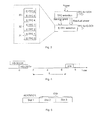
    • determining a power consumption for an acknowledgement/negative acknowledgement transmission on an uplink channel during an enhanced dedicated channel transmission (step 91). According to some embodiments, the ACK/NACK transmission power consumption is determined based on a high speed shared control channel reception;
    • determining a power consumption for a channel quality indicator transmission on an uplink channel during an enhanced dedicated channel transmission (step 92). According to some embodiments the CQI power consumption is determined by using a pre-determined channel quality indicator feedback cycle;
    • selecting a transport format combination based on said determined power consumption (step 93).
According to some embodiments of the present invention, the procedure as shown in FIG. 10, further comprises the steps of:
    • using said determined power consumption for predicting a high speed dedicated physical control channel power consumption during a whole transmission time interval of said enhanced dedicated channel transmission (step 101);
    • determining an available power for said enhanced dedicated channel transmission using said predicted high speed dedicated physical control channel power consumption (step 102); and,
    • selecting said enhanced transport format combination based on said determined available power for said enhanced dedicated channel transmission (step 103).
According to some embodiments of the present invention, the procedure as shown in FIG. 11, further comprises the steps of:
    • using said determined power consumption for predicting available power for each transmission slot of said enhanced dedicated channel transmission (step 111);
    • determining available signal to interference-plus-noise ratio of each transmission slot based on said predicted available power for each transmission slot (step 112);
    • converting said determined available signal to interference-plus-noise ratio of each transmission slot to symbol information of each transmission slot (step 113);
    • determining a received block information for whole transmission time interval of said enhanced dedicated channel transmission based on said symbol information of each slot (step 114);
    • converting said determined received block information to an available effective signal to interference-plus-noise ratio for said whole transmission time interval of said enhanced dedicated channel transmission (step 115);
    • determining an available effective power offset value based on said available effective signal to interference-plus-noise ratio (step 116); and,
    • selecting said enhanced transport format combination based on said determined available effective power offset value (step 117);
    • determining the used power offset of each slot for the selected transport format combination based on the required power offset of the selected transport format combination, the said determined available effective power offset value and the available power offset of each slot (Step 118).
It will be appreciated that at least some of the procedures described above are carried out repetitively as necessary to respond to the time-varying characteristics of the channel between the transmitter and the receiver. To facilitate understanding, many aspects of the invention are described in terms of sequences of actions to be performed by, for example, elements of a programmable computer system. It will be recognized that the various actions could be performed by specialized circuits (e.g. discrete logic gates interconnected to perform a specialized function or application-specific integrated circuits), by program instructions executed by one or more processors, or a combination of both.
Moreover, the invention can additionally be considered to be embodied entirely within any form of computer-readable storage medium having stored therein an appropriate set of instructions for use by or in connection with an instruction-execution system, apparatus or device, such as computer-based system, processor-containing system, or other system that can fetch instructions from a medium and execute the instructions. As used here, a “computer-readable medium” can be any means that can contain, store, communicate, propagate, or transport the program for use by or in connection with the instruction-execution system, apparatus or device. The computer-readable medium can be, for example but not limited to, an electronic, magnetic, optical, electromagnetic, infrared, or semiconductor system, apparatus, device or propagation medium. More specific examples (a non-exhaustive list) of the computer-readable medium include an electrical connection having one or more wires, a portable computer diskette, a random access memory (RAM), a read only memory (ROM), an erasable programmable read only memory (EPROM or Flash memory), an optical fibre, and a portable compact disc read only memory (CD-ROM).
Thus, while there have been shown and described and pointed out fundamental novel features of the invention as applied to a preferred embodiment thereof, it will be understood that various omissions and substitutions and changes in the form and details of the devices illustrated, and in their operation, may be made by those skilled in the art without departing from the spirit of the invention. For example, it is expressly intended that all combinations of those elements and/or method steps which perform substantially the same function in substantially the same way to achieve the same results are within the scope of the invention. Moreover, it should be recognized that structures and/or elements and/or method steps shown and/or described in connection with any disclosed form or embodiment of the invention may be incorporated in any other disclosed or described or suggested form or embodiment as a general matter of design choice. It is the intention, therefore, to be limited only as indicated by the scope of the claims appended hereto.
Expressions such as “including”, “comprising”, “incorporating”, “consisting of”, “have”, “is” used to describe and claim the present invention are intended to be construed in a non-exclusive manner, namely allowing for items, components or elements not explicitly described also to be present. Reference to the singular is also to be construed to relate to the plural and vice versa.
Numerals included within parentheses in the accompanying claims are intended to assist understanding of the claims and should not be construed in any way to limit subject matter claimed by these claims.

Claims (8)

The invention claimed is:
1. A method of selecting an enhanced transport format combination used for maximizing power utilization of and power limitation avoidance in a communication network system comprising a communication network entity communicating with a plurality of user equipments on uplink and downlink channels over a radio interface, comprising:
determining a power consumption for an acknowledgement negative acknowledgement transmission and a channel quality indicator transmission on an uplink channel during an enhanced dedicated channel transmission;
using said determined power consumption for predicting available power for each transmission slot of said enhanced dedicated channel transmission;
determining available signal to interference-plus-noise ratio of each transmission slot based on said predicted available power for each transmission slot;
converting said determined available signal to interference-plus-noise ratio of each transmission slot to symbol information of each transmission slot;
determining a received block information for whole transmission time interval of said enhanced dedicated channel transmission based on said symbol information of each slot;
converting said determined receive block information to an available effective signal to interference-plus-noise ratio for said whole transmission time interval of said enhanced dedicated channel transmission;
determining an available effective power offset value based on said available effective signal to interference-plus-noise ratio; and
selecting said enhanced transport format combination based on said determined available effective power offset value.
2. The method of claim 1, further comprising:
using said determined power consumption for predicting a high speed dedicated physical control channel power consumption during a whole transmission time interval of said enhanced dedicated channel transmission;
determining an available power for said enhanced dedicated channel transmission using said predicted high speed dedicated physical control channel power consumption; and
selecting said enhanced transport format combination based on said determined available power for said enhanced dedicated channel transmission.
3. The method of claim 1, wherein said acknowledgement/negative acknowledgement transmission power consumption is determined based on a high speed shared control channel reception.
4. The method of claim 1, wherein said channel quality indicator power consumption is determined by using a pre-determined channel quality indicator feedback cycle.
5. An arrangement for selecting an enhanced transport format combination used for maximizing power utilization efficiency and power limitation avoidance in a communication network system comprising a communication network entity communicating with a plurality of user equipments on uplink and downlink channels over a radio interface, comprising:
means for determining a power consumption for an acknowledgement/negative acknowledgement transmission and a channel quality indicator transmission on an uplink channel during an enhanced dedicated channel transmission;
means for using said determined power consumption for predicting available power for each transmission slot of said enhanced dedicated channel transmission;
means for determining available signal to interference-plus-noise ratio of each transmission slot based on said predicted available power for each transmission slot;
means for converting said determined available signal to interference-plus-noise ratio of each transmission slot to symbol information of each transmission slot;
means for determining a received block information for whole transmission time interval of said enhanced dedicated channel transmission based on said symbol information of each slot;
means for convening said determined receive block information to an available effective signal to interference-plus-noise ratio for said whole transmission time interval of said enhanced dedicated channel transmission;
means for determining an available effective power offset value based on said available effective signal to interference-plus-noise ratio;
means for selecting said enhanced transport format combination based on said determined available effective power offset value.
6. The arrangement of claim 5, further comprising:
means for using said determined power consumption for predicting a high speed dedicated physical control channel power consumption during a whole transmission time interval of said enhanced dedicated channel transmission;
means for determining an available power for said enhanced dedicated channel transmission using said predicted high speed dedicated physical control channel power consumption; and
means for selecting said enhanced transport format combination based on said determined available power for said enhanced dedicated channel transmission.
7. The arrangement of claim 5, wherein said means for determining an acknowledgement/negative acknowledgement transmission power consumption is arranged to determine said acknowledgement/negative acknowledgement transmission power consumption based on a high speed shared control channel reception.
8. The arrangement of claim 5, wherein said means for determining a channel quality indicator power consumption is arranged to determine said channel quality indicator power consumption by using a pre-determined channel quality indicator feedback cycle.
US13/057,790 2008-08-08 2008-08-08 Method for selecting an enhanced transport format combination based on determined power consumption Active 2029-04-09 US8547952B2 (en)

Applications Claiming Priority (1)

Application Number Priority Date Filing Date Title
PCT/SE2008/050912 WO2010016787A1 (en) 2008-08-08 2008-08-08 Method for selecting an enhanced transport format combination based on determined power consumption

Publications (2)

Publication Number Publication Date
US20110141960A1 US20110141960A1 (en) 2011-06-16
US8547952B2 true US8547952B2 (en) 2013-10-01

Family

ID=41663875

Family Applications (1)

Application Number Title Priority Date Filing Date
US13/057,790 Active 2029-04-09 US8547952B2 (en) 2008-08-08 2008-08-08 Method for selecting an enhanced transport format combination based on determined power consumption

Country Status (3)

Country Link
US (1) US8547952B2 (en)
EP (1) EP2311291B1 (en)
WO (1) WO2010016787A1 (en)

Cited By (10)

* Cited by examiner, † Cited by third party
Publication number Priority date Publication date Assignee Title
US9769769B2 (en) 2014-06-30 2017-09-19 Microsoft Technology Licensing, Llc Detecting proximity using antenna feedback
US9785174B2 (en) * 2014-10-03 2017-10-10 Microsoft Technology Licensing, Llc Predictive transmission power control for back-off
US9813997B2 (en) 2014-01-10 2017-11-07 Microsoft Technology Licensing, Llc Antenna coupling for sensing and dynamic transmission
US9871545B2 (en) 2014-12-05 2018-01-16 Microsoft Technology Licensing, Llc Selective specific absorption rate adjustment
US9871544B2 (en) 2013-05-29 2018-01-16 Microsoft Technology Licensing, Llc Specific absorption rate mitigation
US10013038B2 (en) 2016-01-05 2018-07-03 Microsoft Technology Licensing, Llc Dynamic antenna power control for multi-context device
US10044095B2 (en) 2014-01-10 2018-08-07 Microsoft Technology Licensing, Llc Radiating structure with integrated proximity sensing
US10224974B2 (en) 2017-03-31 2019-03-05 Microsoft Technology Licensing, Llc Proximity-independent SAR mitigation
US10461406B2 (en) 2017-01-23 2019-10-29 Microsoft Technology Licensing, Llc Loop antenna with integrated proximity sensing
US10893488B2 (en) 2013-06-14 2021-01-12 Microsoft Technology Licensing, Llc Radio frequency (RF) power back-off optimization for specific absorption rate (SAR) compliance

Families Citing this family (4)

* Cited by examiner, † Cited by third party
Publication number Priority date Publication date Assignee Title
US8412222B2 (en) * 2008-06-27 2013-04-02 Qualcomm Incorporated Broadcast-multicast transmission with rate adaption
WO2011068726A1 (en) * 2009-12-01 2011-06-09 Spidercloud Wireless, Inc. Method, system and device for high speed uplink packet access scheduling
GB2513122A (en) * 2013-04-15 2014-10-22 Vodafone Intellectual Property Licensing Ltd Uplink control channel overhead reduction
US9769829B2 (en) * 2014-07-28 2017-09-19 Qualcomm Incorporated Techniques for optimizing transmission power allocation in wireless communications

Citations (8)

* Cited by examiner, † Cited by third party
Publication number Priority date Publication date Assignee Title
US20040043783A1 (en) * 2001-12-05 2004-03-04 Ipwireless, Inc. Method and arrangement for power control
EP1560352A1 (en) 2003-08-12 2005-08-03 Matsushita Electric Industrial Co., Ltd. Communication terminal apparatus and transmission power control method
WO2006046893A1 (en) 2004-10-29 2006-05-04 Telefonaktiebolaget Lm Ericsson (Publ) Method and arrangement for mutual information based power control
WO2006113712A1 (en) 2005-04-20 2006-10-26 Interdigital Technology Corporation Method and apparatus for scheduling transmissions via an enhanced dedicated channel
US20070155335A1 (en) 2005-12-30 2007-07-05 Love Robert T Method and apparatus for power reduction for E-TFC selection
EP1811690A1 (en) 2004-10-20 2007-07-25 NEC Corporation Radio communication system, mobile station, base station, radio communication system control method used for the same, and program of the same
US20080013499A1 (en) * 2006-07-13 2008-01-17 Rapeepat Ratasuk Enhanced-transport format combination power margin for uplink
US20130022028A1 (en) * 2005-02-01 2013-01-24 Research In Motion Limited Transmission control method, mobile station, and communication system

Patent Citations (11)

* Cited by examiner, † Cited by third party
Publication number Priority date Publication date Assignee Title
US20040043783A1 (en) * 2001-12-05 2004-03-04 Ipwireless, Inc. Method and arrangement for power control
EP1560352A1 (en) 2003-08-12 2005-08-03 Matsushita Electric Industrial Co., Ltd. Communication terminal apparatus and transmission power control method
US20060111119A1 (en) * 2003-08-12 2006-05-25 Matsushita Electric Industrial Co., Ltd Mobile terminal apparatus and transmission power control method
EP1811690A1 (en) 2004-10-20 2007-07-25 NEC Corporation Radio communication system, mobile station, base station, radio communication system control method used for the same, and program of the same
WO2006046893A1 (en) 2004-10-29 2006-05-04 Telefonaktiebolaget Lm Ericsson (Publ) Method and arrangement for mutual information based power control
US20080132184A1 (en) * 2004-10-29 2008-06-05 Lei Wan Method and Arrangement For Mutual Information Based Power Control
US20130022028A1 (en) * 2005-02-01 2013-01-24 Research In Motion Limited Transmission control method, mobile station, and communication system
WO2006113712A1 (en) 2005-04-20 2006-10-26 Interdigital Technology Corporation Method and apparatus for scheduling transmissions via an enhanced dedicated channel
US20070155335A1 (en) 2005-12-30 2007-07-05 Love Robert T Method and apparatus for power reduction for E-TFC selection
US20080013499A1 (en) * 2006-07-13 2008-01-17 Rapeepat Ratasuk Enhanced-transport format combination power margin for uplink
WO2008008594A2 (en) 2006-07-13 2008-01-17 Motorola Inc. Method, device and network for selecting an enhanced-trans port format combination power margin for uplink

Non-Patent Citations (1)

* Cited by examiner, † Cited by third party
Title
European Office Action issued in EP08794137.3-1246, dated Sep. 18, 2012, 5 pages.

Cited By (12)

* Cited by examiner, † Cited by third party
Publication number Priority date Publication date Assignee Title
US9871544B2 (en) 2013-05-29 2018-01-16 Microsoft Technology Licensing, Llc Specific absorption rate mitigation
US10893488B2 (en) 2013-06-14 2021-01-12 Microsoft Technology Licensing, Llc Radio frequency (RF) power back-off optimization for specific absorption rate (SAR) compliance
US9813997B2 (en) 2014-01-10 2017-11-07 Microsoft Technology Licensing, Llc Antenna coupling for sensing and dynamic transmission
US10044095B2 (en) 2014-01-10 2018-08-07 Microsoft Technology Licensing, Llc Radiating structure with integrated proximity sensing
US10276922B2 (en) 2014-01-10 2019-04-30 Microsoft Technology Licensing, Llc Radiating structure with integrated proximity sensing
US9769769B2 (en) 2014-06-30 2017-09-19 Microsoft Technology Licensing, Llc Detecting proximity using antenna feedback
US9785174B2 (en) * 2014-10-03 2017-10-10 Microsoft Technology Licensing, Llc Predictive transmission power control for back-off
US9871545B2 (en) 2014-12-05 2018-01-16 Microsoft Technology Licensing, Llc Selective specific absorption rate adjustment
US10013038B2 (en) 2016-01-05 2018-07-03 Microsoft Technology Licensing, Llc Dynamic antenna power control for multi-context device
US10461406B2 (en) 2017-01-23 2019-10-29 Microsoft Technology Licensing, Llc Loop antenna with integrated proximity sensing
US10224974B2 (en) 2017-03-31 2019-03-05 Microsoft Technology Licensing, Llc Proximity-independent SAR mitigation
US10924145B2 (en) 2017-03-31 2021-02-16 Microsoft Technology Licensing, Llc Proximity-independent SAR mitigation

Also Published As

Publication number Publication date
EP2311291A4 (en) 2012-09-26
WO2010016787A1 (en) 2010-02-11
US20110141960A1 (en) 2011-06-16
EP2311291A1 (en) 2011-04-20
EP2311291B1 (en) 2014-07-30

Similar Documents

Publication Publication Date Title
US8547952B2 (en) Method for selecting an enhanced transport format combination based on determined power consumption
US8559999B2 (en) Channel quality prediction in HSDPA systems
US8325650B2 (en) Method for reducing delay in a communication system employing HARQ
US9277510B2 (en) Methods and arrangements in a communication network system
US7787430B2 (en) Power control for gated uplink control channel
US8654744B2 (en) Radio communication system, mobile station, base station, radio communication system control method used for the same, and program of the same
CN101207461B (en) Method and apparatus for self-adapting regulation of threshold value
US20070115874A1 (en) Communication control apparatus and communication control method
US20120157152A1 (en) Uplink Power Control
JP4838840B2 (en) Method for scaling an E-DCH channel
US11540305B2 (en) Resource selection for ultra-reliable low-latency communication (URLLC) uplink
CN101106403B (en) A method and device for adjusting transmission power of HSPA downlink physical channel
US20140029454A1 (en) Apparatus and method for transmitting/receiving channel quality indicator in communication system
CN102047746B (en) Technique for radio resource management
US9019907B2 (en) Radio base station
US20140334455A1 (en) Uplink scheduling when using interference suppression
US11963165B2 (en) Resource selection for ultra-reliable low-latency communication (URLLC) uplink
JP5199350B2 (en) User terminal power shortage display
WO2009045134A1 (en) A method of selecting transport format combination
CN102457953B (en) A kind of indicating means of multi-carrier HSUPA power limited, system and terminal

Legal Events

Date Code Title Description
AS Assignment

Owner name: TELEFONAKTIEBOLAGET L M ERICSSON (PUBL), SWEDEN

Free format text: ASSIGNMENT OF ASSIGNORS INTEREST;ASSIGNORS:LIU, JINHUA;MIAO, QINGYU;WANG, MIN;REEL/FRAME:025763/0088

Effective date: 20080811

STCF Information on status: patent grant

Free format text: PATENTED CASE

CC Certificate of correction
FPAY Fee payment

Year of fee payment: 4

AS Assignment

Owner name: GUANGDONG OPPO MOBILE TELECOMMUNICATIONS CORP., LT

Free format text: ASSIGNMENT OF ASSIGNORS INTEREST;ASSIGNOR:TELEFONAKTIEBOLAGET LM ERICSSON (PUBL);REEL/FRAME:049149/0276

Effective date: 20190403

Owner name: GUANGDONG OPPO MOBILE TELECOMMUNICATIONS CORP., LTD., CHINA

Free format text: ASSIGNMENT OF ASSIGNORS INTEREST;ASSIGNOR:TELEFONAKTIEBOLAGET LM ERICSSON (PUBL);REEL/FRAME:049149/0276

Effective date: 20190403

MAFP Maintenance fee payment

Free format text: PAYMENT OF MAINTENANCE FEE, 8TH YEAR, LARGE ENTITY (ORIGINAL EVENT CODE: M1552); ENTITY STATUS OF PATENT OWNER: LARGE ENTITY

Year of fee payment: 8