US8640758B1 - Tracer wire applicator apparatus and method - Google Patents
Tracer wire applicator apparatus and method Download PDFInfo
- Publication number
- US8640758B1 US8640758B1 US13/174,922 US201113174922A US8640758B1 US 8640758 B1 US8640758 B1 US 8640758B1 US 201113174922 A US201113174922 A US 201113174922A US 8640758 B1 US8640758 B1 US 8640758B1
- Authority
- US
- United States
- Prior art keywords
- wire
- frame member
- base frame
- retained
- tape
- Prior art date
- Legal status (The legal status is an assumption and is not a legal conclusion. Google has not performed a legal analysis and makes no representation as to the accuracy of the status listed.)
- Expired - Fee Related, expires
Links
Images


Classifications
-
- B—PERFORMING OPERATIONS; TRANSPORTING
- B29—WORKING OF PLASTICS; WORKING OF SUBSTANCES IN A PLASTIC STATE IN GENERAL
- B29C—SHAPING OR JOINING OF PLASTICS; SHAPING OF MATERIAL IN A PLASTIC STATE, NOT OTHERWISE PROVIDED FOR; AFTER-TREATMENT OF THE SHAPED PRODUCTS, e.g. REPAIRING
- B29C63/00—Lining or sheathing, i.e. applying preformed layers or sheathings of plastics; Apparatus therefor
- B29C63/02—Lining or sheathing, i.e. applying preformed layers or sheathings of plastics; Apparatus therefor using sheet or web-like material
- B29C63/024—Lining or sheathing, i.e. applying preformed layers or sheathings of plastics; Apparatus therefor using sheet or web-like material the sheet or web-like material being supported by a moving carriage
-
- F—MECHANICAL ENGINEERING; LIGHTING; HEATING; WEAPONS; BLASTING
- F16—ENGINEERING ELEMENTS AND UNITS; GENERAL MEASURES FOR PRODUCING AND MAINTAINING EFFECTIVE FUNCTIONING OF MACHINES OR INSTALLATIONS; THERMAL INSULATION IN GENERAL
- F16L—PIPES; JOINTS OR FITTINGS FOR PIPES; SUPPORTS FOR PIPES, CABLES OR PROTECTIVE TUBING; MEANS FOR THERMAL INSULATION IN GENERAL
- F16L1/00—Laying or reclaiming pipes; Repairing or joining pipes on or under water
- F16L1/024—Laying or reclaiming pipes on land, e.g. above the ground
- F16L1/06—Accessories therefor, e.g. anchors
- F16L1/11—Accessories therefor, e.g. anchors for the detection or protection of pipes in the ground
-
- F—MECHANICAL ENGINEERING; LIGHTING; HEATING; WEAPONS; BLASTING
- F16—ENGINEERING ELEMENTS AND UNITS; GENERAL MEASURES FOR PRODUCING AND MAINTAINING EFFECTIVE FUNCTIONING OF MACHINES OR INSTALLATIONS; THERMAL INSULATION IN GENERAL
- F16L—PIPES; JOINTS OR FITTINGS FOR PIPES; SUPPORTS FOR PIPES, CABLES OR PROTECTIVE TUBING; MEANS FOR THERMAL INSULATION IN GENERAL
- F16L2201/00—Special arrangements for pipe couplings
- F16L2201/60—Identification or marking
-
- Y—GENERAL TAGGING OF NEW TECHNOLOGICAL DEVELOPMENTS; GENERAL TAGGING OF CROSS-SECTIONAL TECHNOLOGIES SPANNING OVER SEVERAL SECTIONS OF THE IPC; TECHNICAL SUBJECTS COVERED BY FORMER USPC CROSS-REFERENCE ART COLLECTIONS [XRACs] AND DIGESTS
- Y10—TECHNICAL SUBJECTS COVERED BY FORMER USPC
- Y10T—TECHNICAL SUBJECTS COVERED BY FORMER US CLASSIFICATION
- Y10T156/00—Adhesive bonding and miscellaneous chemical manufacture
- Y10T156/12—Surface bonding means and/or assembly means with cutting, punching, piercing, severing or tearing
- Y10T156/1348—Work traversing type
-
- Y—GENERAL TAGGING OF NEW TECHNOLOGICAL DEVELOPMENTS; GENERAL TAGGING OF CROSS-SECTIONAL TECHNOLOGIES SPANNING OVER SEVERAL SECTIONS OF THE IPC; TECHNICAL SUBJECTS COVERED BY FORMER USPC CROSS-REFERENCE ART COLLECTIONS [XRACs] AND DIGESTS
- Y10—TECHNICAL SUBJECTS COVERED BY FORMER USPC
- Y10T—TECHNICAL SUBJECTS COVERED BY FORMER US CLASSIFICATION
- Y10T156/00—Adhesive bonding and miscellaneous chemical manufacture
- Y10T156/17—Surface bonding means and/or assemblymeans with work feeding or handling means
- Y10T156/1788—Work traversing type and/or means applying work to wall or static structure
- Y10T156/1795—Implement carried web supply
-
- Y—GENERAL TAGGING OF NEW TECHNOLOGICAL DEVELOPMENTS; GENERAL TAGGING OF CROSS-SECTIONAL TECHNOLOGIES SPANNING OVER SEVERAL SECTIONS OF THE IPC; TECHNICAL SUBJECTS COVERED BY FORMER USPC CROSS-REFERENCE ART COLLECTIONS [XRACs] AND DIGESTS
- Y10—TECHNICAL SUBJECTS COVERED BY FORMER USPC
- Y10T—TECHNICAL SUBJECTS COVERED BY FORMER US CLASSIFICATION
- Y10T156/00—Adhesive bonding and miscellaneous chemical manufacture
- Y10T156/18—Surface bonding means and/or assembly means with handle or handgrip
Definitions
- the present invention relates generally to pipes with tracer wires and more specifically to a tracer wire applicator apparatus and method, which allows a tracer wire to be applied to a pipe in an earthen trench.
- Reissue patent no. RE 30,393 to Sherlock discloses a plastic pipe construction.
- U.S. Pat. No. 5,948,201 to Alveskog discloses a method and means for affixing a double sided adhesive tape onto an electric conduit and use thereof.
- Patent application publication no. 2006/0266464 to White discloses a filament tape system & method thereof.
- a tracer wire applicator apparatus and method which allows a tracer wire to be applied to a pipe in an earthen trench for locating a pipe once it is covered or which allows a tracer wire to be manually applied to a pipe.
- the present invention provides a tracer wire applicator apparatus and method, which allows a tracer wire to be manually applied to a pipe.
- the tracer wire applicator preferably includes a base frame, a wire spindle, a tape spindle and a pipe roller.
- the base frame preferably includes a base frame member, a support frame member and an upper frame member.
- the upper frame member preferably includes a curved shape. One end of the upper frame member is removably retained on one end of the base frame member. One end of the support frame member is removably secured to the base frame member and the other end is attached to the upper frame member.
- one end of a handle plate extends from the support frame member and a handle extends from the other end of the handle plate.
- the pipe roller is rotatably retained on the other end of the base frame member.
- the tape spindle is located between the pipe roller and the support frame member.
- a tape roll is rotatably retained on the tape spindle.
- the wire spindle is located between the support frame member and the one end of the base frame member.
- a wire reel is rotatably retained on the wire spindle.
- a wire guide tube is retained in the upper frame member. One end of the wire guide tube is positioned to receive wire from the wire reel and the other end of the wire guide tube is positioned adjacent a middle of the pipe roller.
- the tape roll is placed on the tape spindle, such that a non-adhesive side of the tape is in contact with an outer perimeter of the pipe roller.
- An end of the tape is rolled around the pipe roller, until the tape is aligned with the other end of the wide guide tube.
- the wire reel is placed on the wire spindle.
- An end of the wire on the wire spindle is inserted through the wire guide tube, until the end of the wire is flush with the end of the tape.
- the tracer wire applicator is grasped by both hands.
- the tracer wire applicator is then positioned, such that the outer perimeter of the pipe roller is placed in contact with a pipe.
- the tracer wire applicator is then pulled along a length of the pipe to apply the tape and wire thereto.
- FIG. 1 is a perspective view of a user applying tape and a tracer wire to a pipe with a tracer wire applicator in accordance with the present invention.
- FIG. 2 is a right side view of a tracer wire applicator in accordance with the present invention.
- FIG. 3 is a left side view of a tracer wire applicator in accordance with the present invention.
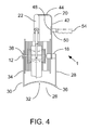
- FIG. 4 is a front end view of a tracer wire applicator in accordance with the present invention.
- FIG. 5 is a perspective view of a tracer wire applicator in accordance with the present invention.
- FIG. 6 is a front view of a pipe roller of a tracer wire applicator in accordance with the present invention.
- FIG. 7 is an end view of a pipe roller of a tracer wire applicator in accordance with the present invention.
- the tracer wire applicator 1 preferably includes a base frame 10 , a wire spindle 12 , a tape spindle 14 and a pipe roller 16 .
- the base frame 10 preferably includes a base frame member 18 , a support frame member 20 and an upper frame member 22 .
- the upper frame member 22 preferably includes a curved shape and a tubular cross section. One end of the upper frame member 22 is removably retained on the one end of the base frame member 18 with any suitable structure.
- An example of a suitable structure would be a projection extending from the one end of the base frame member 18 , which is sized to be slidably received by the tubular cross section of the upper frame member 22 .
- a hand grip 25 is preferably slid on to the one end of the upper frame member 22 , before thereof is secured to the base frame member 18 .
- the one end of the base frame member 18 includes an offset portion 24 .
- the wire spindle 12 extends from substantially a middle of the offset portion 24 .
- the offset portion 24 is provided to center a width of a wire reel 108 relative to the upper frame member 22 .
- the wire spindle 12 is inserted into a spindle hole of the wire reel 108 .
- An applicator rest bracket 26 includes a base plate 28 and a support bracket 30 .
- the support bracket includes a pipe contact leg 32 and a support leg 34 .
- the pipe contact leg 32 includes a curved cross section for resting on a round shaped pipe.
- the support leg 34 extends upward from one end of the pipe contact leg 32 .
- the other end of the support leg 34 is formed into a portion of a hinge and a bottom of the base plate 28 is formed into a mating hinge portion.
- a hinge pin 36 is inserted into the hinge and mating portions to pivotally engage the base plate 28 with the support leg 34 .
- a top of the base plate 28 is preferably attached to the base frame member 18 with welding or fasteners.
- a hole is formed through the support leg 34 to receive an end of the wire spindle 12 .
- a thread is preferably formed on an end of the wire spindle 12 to threadably receive a wing nut 38 or the like.
- the support leg 34 is removed from the wire spindle 12
- the support frame member 20 includes a support leg 42 and a cross leg 44 .
- One end of the support leg 42 is preferably attached to the base frame member 18 with fasteners 46 .
- the cross leg 44 is preferably welded to the upper frame member 22 .
- One end of a handle plate 48 is attached to the support leg 44 with welding or the like.
- a handle 50 is secured to the other end of the handle plate 48 with a fastener 52 .
- a handle grip 54 is preferably slid on to the handle 50 .
- the pipe roller 16 is rotatably retained on the other end of the base frame member 18 with a roller spindle 56 and a fastener 58 or the like. With reference to FIGS. 6-7 , the roller spindle 56 is inserted into a spindle hole 60 of the pipe roller 16 .
- the pipe roller 16 is axially retained with the fastener 58 .
- the pipe roller 16 preferably includes a concave profile 62 to receive an outer diameter of a round shaped pipe.
- a plurality of slots 64 are preferably formed in a circumference of the pipe roller 16 .
- the plurality of slots 64 facilitate the flexing of the pipe roller 16 for different diameter of pipes.
- the plurality of slots 64 also allow the tape to be attached to a pipe with some moisture thereon. The moisture pushes a portion of the tape 102 into the plurality of slots 64 .
- the tape spindle 14 extends from the base frame 18 .
- the tape spindle 14 is located between the pipe roller 16 and the support frame member 20 .
- a tape roll 110 is rotatably retained on the tape spindle 14 .
- the tape roll 110 is preferably axially secured on the tape spindle 14 with a wing nut 66 or the like.
- a wire guide tube 68 is preferably retained in the upper frame member 22 .
- the wire guide tube 68 preferably includes a flexible tube 70 , a rigid tube 72 and a retention plug 74 .
- the retention plug 74 includes a bore which is sized to slidably receive the rigid tube 72 .
- a portion of an outer diameter of the retention plug 74 is sized to be received by an inner perimeter of the upper frame member 22 .
- the flexible tube 70 is inserted into the rigid tube 72 .
- One end of the flexible tube 70 preferably extends from one end of the rigid tube 72 to receive the wire 104 .
- the wire 104 preferably includes at least one conductive wire and an insulated outer cover.
- the other end of the flexible tube 70 preferably extends from the other end of the rigid tube 72 , adjacent the outer perimeter of the pipe roller 16 .
- An angular hole is formed through the upper frame member 22 for insertion of the rigid tube 72 .
- the rigid tube 72 is inserted through the angular hole and out of the other end of the upper frame member 22 .
- the retention plug 74 is slid over the rigid tube 72 and inserted into the other end of the upper frame member 22 .
- the rigid tube 72 does not have to be inserted into the upper frame member 22 , but may be retained relative to the base frame 10 with any suitable structure.
- the flexible tube 70 bends to accommodate the wire 104 unreeling from the wire reel 108 .
- the flexible tube 70 is preferably fabricated from a polyurethane material, but other materials may also be used.
- the rigid tube 72 is preferably fabricated from stainless steel to prevent corrosion.
- a fastener 76 is threaded through the upper frame member 22 , the retention plug 74 and into a side of the rigid tube 72 to axially retain the rigid tube 72 relative to the frame member 22 .
- the tape roll 110 is secured to the tape spindle 14 , such that a non-adhesive side of the tape 102 is in contact with an outer perimeter of the pipe roller 16 .
- An end of the tape 102 is rolled around the pipe roller 16 , until the tape 102 is aligned with the other end of the wire guide tube 68 .
- the wire reel 108 is secured to the wire spindle 12 .
- An end of the wire on the wire spindle is inserted through the wire guide tube 68 , until the end of the wire is flush with the end of the tape 102 .
- the hand grips 25 , 54 of the tracer wire applicator 1 are grasped by both hands.
- the tracer wire applicator 1 is then positioned, such that the outer perimeter of the pipe roller 16 is placed in contact with the pipe 106 .
- the tracer wire applicator 1 is then pulled along a length of the pipe 106 to apply the tape 102 and the wire 104 thereto.
- a voltage is applied across the wire 104 from one end of the pipe 106 to the other end of the pipe 106 to verify continuity of the wire 104 .
Abstract
A tracer wire applicator preferably includes a base frame, a wire spindle, a tape spindle and a pipe roller. The base frame preferably includes a base frame member, a support frame member and an upper frame member. One end of the upper frame member is removably secured to one end of the base frame member. One end of the support frame member is removably attached to the base frame member and the other end is attached to the upper frame member. The pipe roller is rotatably retained on the other end of the base frame member. The tape spindle extends from the base frame member to rotatably receive a roll of tape. A wire spindle extends from the base frame member to rotatably receive a wire reel. A wire guide tube is preferably retained by the upper frame member.
Description
1. Field of the Invention
The present invention relates generally to pipes with tracer wires and more specifically to a tracer wire applicator apparatus and method, which allows a tracer wire to be applied to a pipe in an earthen trench.
2. Discussion of the Prior Art
Reissue patent no. RE 30,393 to Sherlock discloses a plastic pipe construction. U.S. Pat. No. 5,948,201 to Alveskog discloses a method and means for affixing a double sided adhesive tape onto an electric conduit and use thereof. Patent application publication no. 2006/0266464 to White discloses a filament tape system & method thereof.
Accordingly, there is a clearly felt need in the art for a tracer wire applicator apparatus and method, which allows a tracer wire to be applied to a pipe in an earthen trench for locating a pipe once it is covered or which allows a tracer wire to be manually applied to a pipe.
The present invention provides a tracer wire applicator apparatus and method, which allows a tracer wire to be manually applied to a pipe. The tracer wire applicator preferably includes a base frame, a wire spindle, a tape spindle and a pipe roller. The base frame preferably includes a base frame member, a support frame member and an upper frame member. The upper frame member preferably includes a curved shape. One end of the upper frame member is removably retained on one end of the base frame member. One end of the support frame member is removably secured to the base frame member and the other end is attached to the upper frame member. Preferably, one end of a handle plate extends from the support frame member and a handle extends from the other end of the handle plate.
The pipe roller is rotatably retained on the other end of the base frame member. The tape spindle is located between the pipe roller and the support frame member. A tape roll is rotatably retained on the tape spindle. The wire spindle is located between the support frame member and the one end of the base frame member. A wire reel is rotatably retained on the wire spindle. A wire guide tube is retained in the upper frame member. One end of the wire guide tube is positioned to receive wire from the wire reel and the other end of the wire guide tube is positioned adjacent a middle of the pipe roller.
In use, the tape roll is placed on the tape spindle, such that a non-adhesive side of the tape is in contact with an outer perimeter of the pipe roller. An end of the tape is rolled around the pipe roller, until the tape is aligned with the other end of the wide guide tube. The wire reel is placed on the wire spindle. An end of the wire on the wire spindle is inserted through the wire guide tube, until the end of the wire is flush with the end of the tape. The tracer wire applicator is grasped by both hands. The tracer wire applicator is then positioned, such that the outer perimeter of the pipe roller is placed in contact with a pipe. The tracer wire applicator is then pulled along a length of the pipe to apply the tape and wire thereto.
Accordingly, it is an object of the present invention to provide a tracer wire applicator apparatus and method, which allows a tracer wire to be manually applied to a pipe.
Finally, it is another object of the present invention to provide a tracer wire applicator apparatus and method, which allows a tracer wire to be applied to a pipe in an earthen trench for locating a pipe once it is covered.
These and additional objects, advantages, features and benefits of the present invention will become apparent from the following specification.
With reference now to the drawings, and particularly to FIG. 1 , there is shown a perspective view of a user 100 applying tape 102 and a tracer wire 104 to a pipe 106 with a tracer wire applicator 1. With reference to FIGS. 2-5 , the tracer wire applicator 1 preferably includes a base frame 10, a wire spindle 12, a tape spindle 14 and a pipe roller 16. The base frame 10 preferably includes a base frame member 18, a support frame member 20 and an upper frame member 22. The upper frame member 22 preferably includes a curved shape and a tubular cross section. One end of the upper frame member 22 is removably retained on the one end of the base frame member 18 with any suitable structure. An example of a suitable structure would be a projection extending from the one end of the base frame member 18, which is sized to be slidably received by the tubular cross section of the upper frame member 22. A hand grip 25 is preferably slid on to the one end of the upper frame member 22, before thereof is secured to the base frame member 18. The one end of the base frame member 18 includes an offset portion 24. The wire spindle 12 extends from substantially a middle of the offset portion 24. The offset portion 24 is provided to center a width of a wire reel 108 relative to the upper frame member 22. The wire spindle 12 is inserted into a spindle hole of the wire reel 108.
An applicator rest bracket 26 includes a base plate 28 and a support bracket 30. The support bracket includes a pipe contact leg 32 and a support leg 34. The pipe contact leg 32 includes a curved cross section for resting on a round shaped pipe. The support leg 34 extends upward from one end of the pipe contact leg 32. The other end of the support leg 34 is formed into a portion of a hinge and a bottom of the base plate 28 is formed into a mating hinge portion. A hinge pin 36 is inserted into the hinge and mating portions to pivotally engage the base plate 28 with the support leg 34. A top of the base plate 28 is preferably attached to the base frame member 18 with welding or fasteners. A hole is formed through the support leg 34 to receive an end of the wire spindle 12. A thread is preferably formed on an end of the wire spindle 12 to threadably receive a wing nut 38 or the like. The support leg 34 is removed from the wire spindle 12 for the installation or removal of the wire reel 108.
The support frame member 20 includes a support leg 42 and a cross leg 44. One end of the support leg 42 is preferably attached to the base frame member 18 with fasteners 46. The cross leg 44 is preferably welded to the upper frame member 22. One end of a handle plate 48 is attached to the support leg 44 with welding or the like. A handle 50 is secured to the other end of the handle plate 48 with a fastener 52. A handle grip 54 is preferably slid on to the handle 50.
The pipe roller 16 is rotatably retained on the other end of the base frame member 18 with a roller spindle 56 and a fastener 58 or the like. With reference to FIGS. 6-7 , the roller spindle 56 is inserted into a spindle hole 60 of the pipe roller 16. The pipe roller 16 is axially retained with the fastener 58. The pipe roller 16 preferably includes a concave profile 62 to receive an outer diameter of a round shaped pipe. A plurality of slots 64 are preferably formed in a circumference of the pipe roller 16. The plurality of slots 64 facilitate the flexing of the pipe roller 16 for different diameter of pipes. The plurality of slots 64 also allow the tape to be attached to a pipe with some moisture thereon. The moisture pushes a portion of the tape 102 into the plurality of slots 64.
The tape spindle 14 extends from the base frame 18. The tape spindle 14 is located between the pipe roller 16 and the support frame member 20. A tape roll 110 is rotatably retained on the tape spindle 14. The tape roll 110 is preferably axially secured on the tape spindle 14 with a wing nut 66 or the like. A wire guide tube 68 is preferably retained in the upper frame member 22. The wire guide tube 68 preferably includes a flexible tube 70, a rigid tube 72 and a retention plug 74. The retention plug 74 includes a bore which is sized to slidably receive the rigid tube 72. A portion of an outer diameter of the retention plug 74 is sized to be received by an inner perimeter of the upper frame member 22.
The flexible tube 70 is inserted into the rigid tube 72. One end of the flexible tube 70 preferably extends from one end of the rigid tube 72 to receive the wire 104. The wire 104 preferably includes at least one conductive wire and an insulated outer cover. The other end of the flexible tube 70 preferably extends from the other end of the rigid tube 72, adjacent the outer perimeter of the pipe roller 16. An angular hole is formed through the upper frame member 22 for insertion of the rigid tube 72. The rigid tube 72 is inserted through the angular hole and out of the other end of the upper frame member 22. The retention plug 74 is slid over the rigid tube 72 and inserted into the other end of the upper frame member 22.
However, the rigid tube 72 does not have to be inserted into the upper frame member 22, but may be retained relative to the base frame 10 with any suitable structure. The flexible tube 70 bends to accommodate the wire 104 unreeling from the wire reel 108. The flexible tube 70 is preferably fabricated from a polyurethane material, but other materials may also be used. The rigid tube 72 is preferably fabricated from stainless steel to prevent corrosion. A fastener 76 is threaded through the upper frame member 22, the retention plug 74 and into a side of the rigid tube 72 to axially retain the rigid tube 72 relative to the frame member 22.
In use, the tape roll 110 is secured to the tape spindle 14, such that a non-adhesive side of the tape 102 is in contact with an outer perimeter of the pipe roller 16. An end of the tape 102 is rolled around the pipe roller 16, until the tape 102 is aligned with the other end of the wire guide tube 68. The wire reel 108 is secured to the wire spindle 12. An end of the wire on the wire spindle is inserted through the wire guide tube 68, until the end of the wire is flush with the end of the tape 102. The hand grips 25, 54 of the tracer wire applicator 1 are grasped by both hands. The tracer wire applicator 1 is then positioned, such that the outer perimeter of the pipe roller 16 is placed in contact with the pipe 106. The tracer wire applicator 1 is then pulled along a length of the pipe 106 to apply the tape 102 and the wire 104 thereto. After the wire 104 is attached to the pipe 106 with the tape 102, a voltage is applied across the wire 104 from one end of the pipe 106 to the other end of the pipe 106 to verify continuity of the wire 104.
While particular embodiments of the invention have been shown and described, it will be obvious to those skilled in the art that changes and modifications may be made without departing from the invention in its broader aspects, and therefore, the aim in the appended claims is to cover all such changes and modifications as fall within the true spirit and scope of the invention.
Claims (6)
1. A tracer wire applicator comprising:
a base frame includes a base frame member, a support frame member and a upper frame member, one end of said base frame is removably attached to one end of said upper frame member, one end of said support frame member is removably attached to said base frame, the other end of said support frame member is attached to said upper frame member, said upper frame member having a substantially curved portion and a tubular cross section;
a wire spindle is retained on substantially one end of said base frame to rotatably retain a wire reel;
a tape spindle is retained on substantially the other end of said base frame to rotatably retain a tape roll;
a pipe roller is rotatably retained on the other end of said base frame; and
a wire guide tube is retained by said base frame, one end of said wire guide tube receives wire from the wire reel, the other end of said wire guide tube is located adjacent said pipe roller, said wire guide tube includes a flexible tube and a rigid tube, said flexible tube extends from each end of said rigid tube, a portion of said wire guide tube is retained in said tubular cross section, wherein the tape from the tape roll is placed in contact with an outer perimeter of said pipe roller, the wire from the wire reel is placed in contact with an adhesive side of the tape.
2. The tracer wire applicator of claim 1 , further comprising:
an application rest bracket includes a base plate and a support bracket, one end of said base plate is attached to said base frame, one end of said support bracket is retained on said wire spindle, the other end of said support bracket is pivotally retained by the other end of said base plate.
3. A tracer wire applicator comprising:
a base frame includes a base frame member, a support frame member and a upper frame member, one end of said base frame is removably attached to one end of said upper frame member, one end of said support frame member is removably attached to said base frame, the other end of said support frame member is attached to said upper frame member, said upper frame member having a substantially curved portion and a tubular cross section;
a handle extends from said support frame member;
a wire spindle is retained on substantially one end of said base frame to rotatably retain a wire reel;
a tape spindle is retained on substantially the other end of said base frame to rotatably retain a tape roll;
a pipe roller is rotatably retained on the other end of said base frame; and
a wire guide tube is retained by said base frame, one end of said wire guide tube receives wire from the wire reel, the other end of said wire guide tube is located adjacent said pipe roller, said wire guide tube includes a flexible tube and a rigid tube, said flexible tube extends from each end of said rigid tube, a portion of said wire guide tube is retained in said tubular cross section, wherein the tape from the tape roll is placed in contact with an outer perimeter of said pipe roller, the wire from the wire reel is placed in contact with an adhesive side of the tape.
4. The tracer wire applicator of claim 3 , further comprising:
an application rest bracket includes a base plate and a support bracket, one end of said base plate is attached to said base frame, one end of said support bracket is retained on said wire spindle, the other end of said support bracket is pivotally retained by the other end of said base plate.
5. A tracer wire applicator comprising:
a base frame includes a base frame member, a support frame member and a upper frame member, one end of said base frame is removably attached to one end of said upper frame member, one end of said support frame member is removably attached to said base frame, the other end of said support frame member is attached to said upper frame member, said upper frame member having a substantially curved portion and a tubular cross section, substantially one end of said base frame is offset to center a wire reel relative to said upper frame member;
a handle extends from said support frame member;
a wire spindle is retained on substantially one end of said base frame to rotatably retain a wire reel;
a tape spindle is retained on substantially the other end of said base frame to rotatably retain a tape roll;
a pipe roller is rotatably retained on the other end of said base frame; and
a wire guide tube is retained by said base frame, one end of said wire guide tube receives wire from the wire reel, the other end of said wire guide tube is located adjacent said pipe roller, said wire guide tube includes a flexible tube and a rigid tube, said flexible tube extends from each end of said rigid tube, a portion of said wire guide tube is retained in said tubular cross section, wherein the tape from the tape roll is placed in contact with an outer perimeter of said pipe roller, the wire from the wire reel is placed in contact with an adhesive side of the tape.
6. The tracer wire applicator of claim 5 , further comprising:
an application rest bracket includes a base plate and a support bracket, one end of said base plate is attached to said base frame, one end of said support bracket is retained on said wire spindle, the other end of said support bracket is pivotally retained by the other end of said base plate.
Priority Applications (1)
| Application Number | Priority Date | Filing Date | Title |
|---|---|---|---|
| US13/174,922 US8640758B1 (en) | 2011-07-01 | 2011-07-01 | Tracer wire applicator apparatus and method |
Applications Claiming Priority (1)
| Application Number | Priority Date | Filing Date | Title |
|---|---|---|---|
| US13/174,922 US8640758B1 (en) | 2011-07-01 | 2011-07-01 | Tracer wire applicator apparatus and method |
Publications (1)
| Publication Number | Publication Date |
|---|---|
| US8640758B1 true US8640758B1 (en) | 2014-02-04 |
Family
ID=50001524
Family Applications (1)
| Application Number | Title | Priority Date | Filing Date |
|---|---|---|---|
| US13/174,922 Expired - Fee Related US8640758B1 (en) | 2011-07-01 | 2011-07-01 | Tracer wire applicator apparatus and method |
Country Status (1)
| Country | Link |
|---|---|
| US (1) | US8640758B1 (en) |
Cited By (2)
| Publication number | Priority date | Publication date | Assignee | Title |
|---|---|---|---|---|
| US20140130983A1 (en) * | 2012-04-06 | 2014-05-15 | Thomas Frederick | Tape Dispensers |
| US20230194020A1 (en) * | 2020-07-15 | 2023-06-22 | Tracer Way Inc. | Tracer wire holder |
Citations (6)
| Publication number | Priority date | Publication date | Assignee | Title |
|---|---|---|---|---|
| US3175679A (en) * | 1962-06-22 | 1965-03-30 | American Chain & Cable Co | Coiled wire package |
| USRE30393E (en) | 1979-03-26 | 1980-09-02 | Western Packing And Supply Company | Plastic pipe construction |
| US4415400A (en) * | 1981-03-25 | 1983-11-15 | Paul Rammelmeyr | Device for joining two single adhesive tapes to form a double adhesive tape |
| US5948201A (en) | 1995-02-06 | 1999-09-07 | Alveskog; Hans | Method and means for affixing a double sided adhesive tape onto an electric conduit and use thereof |
| US20060266464A1 (en) * | 2005-05-24 | 2006-11-30 | Mark White | Filament tape system & method thereof |
| US20100300625A1 (en) * | 2009-05-27 | 2010-12-02 | Thelbert David Hardy | Hand held dual sided tape dispensing machine |
-
2011
- 2011-07-01 US US13/174,922 patent/US8640758B1/en not_active Expired - Fee Related
Patent Citations (6)
| Publication number | Priority date | Publication date | Assignee | Title |
|---|---|---|---|---|
| US3175679A (en) * | 1962-06-22 | 1965-03-30 | American Chain & Cable Co | Coiled wire package |
| USRE30393E (en) | 1979-03-26 | 1980-09-02 | Western Packing And Supply Company | Plastic pipe construction |
| US4415400A (en) * | 1981-03-25 | 1983-11-15 | Paul Rammelmeyr | Device for joining two single adhesive tapes to form a double adhesive tape |
| US5948201A (en) | 1995-02-06 | 1999-09-07 | Alveskog; Hans | Method and means for affixing a double sided adhesive tape onto an electric conduit and use thereof |
| US20060266464A1 (en) * | 2005-05-24 | 2006-11-30 | Mark White | Filament tape system & method thereof |
| US20100300625A1 (en) * | 2009-05-27 | 2010-12-02 | Thelbert David Hardy | Hand held dual sided tape dispensing machine |
Cited By (3)
| Publication number | Priority date | Publication date | Assignee | Title |
|---|---|---|---|---|
| US20140130983A1 (en) * | 2012-04-06 | 2014-05-15 | Thomas Frederick | Tape Dispensers |
| US20230194020A1 (en) * | 2020-07-15 | 2023-06-22 | Tracer Way Inc. | Tracer wire holder |
| US11873922B2 (en) * | 2020-07-15 | 2024-01-16 | Tracer Way Inc. | Tracer wire holder |
Similar Documents
| Publication | Publication Date | Title |
|---|---|---|
| US11228162B2 (en) | Wire pulling head apparatus with crimp zone indicators and method of using same | |
| US8985541B2 (en) | Cable roller, system and/or method for extending and/or retracting a coiled cable | |
| JP5567592B2 (en) | Ingrown nail correction device | |
| US9111512B2 (en) | Drumstick grip | |
| US8640758B1 (en) | Tracer wire applicator apparatus and method | |
| US20130098557A1 (en) | Device and method for optical cable installation | |
| US20190061275A1 (en) | Tape applicator assembly and tape assembly | |
| CA2938012C (en) | Tape applicator assembly and tape assembly | |
| US20100090183A1 (en) | Apparatus for use in advancing a cable through a conduit | |
| US7040370B2 (en) | Hand tool for holding a tape spool | |
| US20230383872A1 (en) | Flexible Hose, more Particularly Vacuum Cleaner Hose, Method for Production of Same and Device Which can be Used Herefor | |
| US20150210496A1 (en) | Tape assembly | |
| KR200413666Y1 (en) | A Reel for Winding Electric Wire possible Automatic Lineup | |
| US20040108404A1 (en) | Insulation rolling system | |
| US20090166461A1 (en) | Fire Hose Reel | |
| US20060289107A1 (en) | Wallpaper border holder/positioning device | |
| KR200411000Y1 (en) | A roller handle of remove tape a dust | |
| EP2962974B1 (en) | Cable drum with a fixing and positioning device | |
| US9476209B2 (en) | Drywall tape dispenser actuated using a drill | |
| KR102246377B1 (en) | Tape Applying Device | |
| US7698971B1 (en) | Foot peg engaging tool | |
| GB2517208A (en) | A roofing material dispenser | |
| US20050173582A1 (en) | Helically coiled garden hose holder | |
| US20070290018A1 (en) | Tape dispensing and cutting device | |
| US20080052893A1 (en) | Bending of insulated pipe |
Legal Events
| Date | Code | Title | Description |
|---|---|---|---|
| STCF | Information on status: patent grant |
Free format text: PATENTED CASE |
|
| CC | Certificate of correction | ||
| FPAY | Fee payment |
Year of fee payment: 4 |
|
| FEPP | Fee payment procedure |
Free format text: MAINTENANCE FEE REMINDER MAILED (ORIGINAL EVENT CODE: REM.); ENTITY STATUS OF PATENT OWNER: MICROENTITY |
|
| LAPS | Lapse for failure to pay maintenance fees |
Free format text: PATENT EXPIRED FOR FAILURE TO PAY MAINTENANCE FEES (ORIGINAL EVENT CODE: EXP.); ENTITY STATUS OF PATENT OWNER: MICROENTITY |
|
| STCH | Information on status: patent discontinuation |
Free format text: PATENT EXPIRED DUE TO NONPAYMENT OF MAINTENANCE FEES UNDER 37 CFR 1.362 |
|
| FP | Lapsed due to failure to pay maintenance fee |
Effective date: 20220204 |