US8852006B2 - Observation wheel - Google Patents
Observation wheel Download PDFInfo
- Publication number
- US8852006B2 US8852006B2 US13/701,258 US201113701258A US8852006B2 US 8852006 B2 US8852006 B2 US 8852006B2 US 201113701258 A US201113701258 A US 201113701258A US 8852006 B2 US8852006 B2 US 8852006B2
- Authority
- US
- United States
- Prior art keywords
- groups
- shaped element
- outer ring
- passenger units
- observation wheel
- Prior art date
- Legal status (The legal status is an assumption and is not a legal conclusion. Google has not performed a legal analysis and makes no representation as to the accuracy of the status listed.)
- Expired - Fee Related
Links
Images


Classifications
-
- A—HUMAN NECESSITIES
- A63—SPORTS; GAMES; AMUSEMENTS
- A63G—MERRY-GO-ROUNDS; SWINGS; ROCKING-HORSES; CHUTES; SWITCHBACKS; SIMILAR DEVICES FOR PUBLIC AMUSEMENT
- A63G27/00—Russian swings; Great wheels, e.g. Ferris wheels
Definitions
- the present invention relates to the amusement industry.
- the disadvantage of the known device is considerable metal consumption resulting from unpractical and inefficient arrangement of passenger units (gondolas) along the outer ring-shaped element of the load-bearing structure and from use of a great number of radial elements. Presence of a large number of radial members causes an increase in wind load acting on an observation wheel structure.
- the embodiments of the present invention are aimed to remove the said disadvantage by providing an optimal ratio between the number of passenger units and radial elements.
- the said objective is accomplished through a special arrangement of passenger units in the observation wheel which suggests that in said observation wheel comprising passenger units fixed on the outer ring-shaped element of the load-bearing structure provided with radial members said passenger units are arranged in groups the circumferential distances between which exceed those between the passenger units within the groups, and at the same time said outer ring-shaped element is reinforced in the areas of the groups location.
- Groups can include at least two passenger units.
- Groups of passenger units may include both open and closed gondolas.
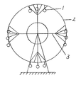
- FIG. 1 is a view of the first modification of the panoramic wheel
- FIG. 2 is a view of the second modification of the panoramic wheel.
- the observation wheel comprises passenger units (gondolas) 1 which are fixed on the outer ring-shaped element 2 of the load-bearing structure provided with radial members 3 .
- the passenger units 1 are arranged in groups the circumferential distances between which exceed those between the passenger units within the groups. The number of passenger units in each group is determined by the diameter of the load-bearing structure and required throughput of the observation wheel.
- the outer ring-shaped element is provided with reinforcement made, for example, with increase of the section stiffness toward its center.
- the reinforcement of the said ring-shaped element can be implemented through execution of the connection by structural means.
- the said observation wheel operates similarly to the known observation wheels.
Landscapes
- Rolling Contact Bearings (AREA)
- Braking Arrangements (AREA)
Abstract
The observation wheel is the arrangement of passenger modules in groups with a distance between the groups circumferentially which exceeds the distance circumferentially between the passenger modules in the groups. An outer annular element is reinforced in the areas in which the groups are arranged.
Description
The present invention relates to the amusement industry.
It has formerly been proposed an observation wheel comprising passenger units mounted on an outer ring-shaped element of the load-bearing structure provided with radial members (see the RF patent No. 2211070 dtd. 18 Jan., 2002).
The disadvantage of the known device is considerable metal consumption resulting from unpractical and inefficient arrangement of passenger units (gondolas) along the outer ring-shaped element of the load-bearing structure and from use of a great number of radial elements. Presence of a large number of radial members causes an increase in wind load acting on an observation wheel structure.
The embodiments of the present invention are aimed to remove the said disadvantage by providing an optimal ratio between the number of passenger units and radial elements.
The said objective is accomplished through a special arrangement of passenger units in the observation wheel which suggests that in said observation wheel comprising passenger units fixed on the outer ring-shaped element of the load-bearing structure provided with radial members said passenger units are arranged in groups the circumferential distances between which exceed those between the passenger units within the groups, and at the same time said outer ring-shaped element is reinforced in the areas of the groups location.
Groups can include at least two passenger units.
In the first modification of the observation wheel groups of passenger units or parts thereof are arranged within the areas of connection of radial members to the outer ring-shaped element, and in the second modification groups of passenger units or parts thereof are arranged between the areas of connection of radial members to the outer ring-shaped element.
Groups of passenger units may include both open and closed gondolas.
Essence of the invention is illustrated by the appended drawings in which:
The observation wheel comprises passenger units (gondolas) 1 which are fixed on the outer ring-shaped element 2 of the load-bearing structure provided with radial members 3. The passenger units 1 are arranged in groups the circumferential distances between which exceed those between the passenger units within the groups. The number of passenger units in each group is determined by the diameter of the load-bearing structure and required throughput of the observation wheel.
In the areas of said groups of passenger units location the outer ring-shaped element is provided with reinforcement made, for example, with increase of the section stiffness toward its center. When passenger units are located within the area of connection of a radial member to the outer ring-shaped element the reinforcement of the said ring-shaped element can be implemented through execution of the connection by structural means.
The said observation wheel operates similarly to the known observation wheels.
Claims (6)
1. An observation wheel, comprising:
a load-bearing structure comprising an outer ring-shaped element having a center and an outer peripheral edge, and a plurality of radial members extending radially outwardly from said center of said outer ring-shaped element to said outer peripheral edge of said outer ring-shaped element;
a plurality of passenger units all of which are fixed to said outer peripheral edge of the same outer ring-shaped element of said load-bearing structure, wherein said passenger units are arranged in a plurality of groups along said outer peripheral edge of the same outer ring-shaped element, wherein the circumferential distances between said groups of passenger units within the same outer ring-shaped element exceeds the circumferential distances between said passenger units within said groups, and wherein said outer ring-shaped element is reinforced in areas of said groups.
2. The observation wheel according to claim 1 , wherein:
said groups comprise at least two passenger units.
3. The observation wheel according to claim 1 , wherein:
at least a portion of said groups of passenger units are located within said areas of connection of said radial members to said outer ring-shaped element.
4. The observation wheel according to claim 1 , wherein:
at least a portion of said groups of passenger units are located between said areas of connection of said radial members to said outer ring-shaped element.
5. The observation wheel according to claim 1 , wherein:
said groups of passenger units comprise a member selected from the group consisting of open gondolas and closed gondolas.
6. The observation wheel according to claim 1 , wherein:
said load-bearing structure comprises a single outer ring-shaped element.
Applications Claiming Priority (3)
| Application Number | Priority Date | Filing Date | Title |
|---|---|---|---|
| RU2010128213/12A RU2438746C1 (en) | 2010-07-08 | 2010-07-08 | Ferris wheel |
| RU2010128213 | 2010-07-08 | ||
| PCT/RU2011/000688 WO2012011852A2 (en) | 2010-07-08 | 2011-09-08 | Observation wheel |
Publications (2)
| Publication Number | Publication Date |
|---|---|
| US20130095936A1 US20130095936A1 (en) | 2013-04-18 |
| US8852006B2 true US8852006B2 (en) | 2014-10-07 |
Family
ID=45497337
Family Applications (1)
| Application Number | Title | Priority Date | Filing Date |
|---|---|---|---|
| US13/701,258 Expired - Fee Related US8852006B2 (en) | 2010-07-08 | 2011-09-08 | Observation wheel |
Country Status (4)
| Country | Link |
|---|---|
| US (1) | US8852006B2 (en) |
| EP (1) | EP2591835A4 (en) |
| RU (1) | RU2438746C1 (en) |
| WO (1) | WO2012011852A2 (en) |
Cited By (1)
| Publication number | Priority date | Publication date | Assignee | Title |
|---|---|---|---|---|
| US20150231514A1 (en) * | 2012-10-01 | 2015-08-20 | Vladimir Alexeevich Gnezdilov | Ferris wheel, units therefor and device for installing same |
Families Citing this family (4)
| Publication number | Priority date | Publication date | Assignee | Title |
|---|---|---|---|---|
| US9821235B2 (en) | 2013-02-26 | 2017-11-21 | Haskel Mayer | Habitable support structure for observation wheels |
| RU2544146C2 (en) * | 2013-06-26 | 2015-03-10 | Владимир Алексеевич Гнездилов | Big dipper (versions) |
| US10535003B2 (en) | 2013-09-20 | 2020-01-14 | Namesforlife, Llc | Establishing semantic equivalence between concepts |
| CN111701248A (en) | 2014-07-09 | 2020-09-25 | H·迈尔 | Inhabitable supporting structure for viewing ferris wheel |
Citations (8)
| Publication number | Priority date | Publication date | Assignee | Title |
|---|---|---|---|---|
| US535362A (en) * | 1895-03-12 | Vertical rotary swing | ||
| US809937A (en) | 1904-06-15 | 1906-01-16 | Henry W Carter | Amusement apparatus. |
| US899286A (en) | 1908-04-13 | 1908-09-22 | Achille F Biavati | Car for observation-wheels. |
| US2320555A (en) | 1941-01-22 | 1943-06-01 | Marjorie Bartlett | Amusement apparatus |
| US3226113A (en) * | 1963-11-19 | 1965-12-28 | Charles H Mercer | Collapsible wheel structure for rotary amusement devices |
| US3456943A (en) * | 1966-07-27 | 1969-07-22 | Chance Mfg Co Inc | Amusement ride apparatus and method |
| US3552747A (en) * | 1969-02-06 | 1971-01-05 | Bridge Eli Co | Portable folding ferris wheel |
| US4815728A (en) | 1987-12-01 | 1989-03-28 | Keefe Stephen J O | Amusement ride |
Family Cites Families (4)
| Publication number | Priority date | Publication date | Assignee | Title |
|---|---|---|---|---|
| DE2937703A1 (en) * | 1979-09-18 | 1981-04-02 | Anton 8909 Münsterhausen Schwarzkopf | Giant wheel spoke structure - is in two latticework girder halves hinging together half-way along |
| RU2211070C1 (en) * | 2002-01-18 | 2003-08-27 | Гнездилов Владимир Алексеевич | Viewing wheel (versions) |
| NL1027850C1 (en) * | 2004-12-22 | 2006-06-30 | Kig Heerenveen Bv | Fairground attraction with a person carrier (s) suspended from a rotatable arm, kept flat during rotation. |
| RU2358787C2 (en) * | 2007-01-11 | 2009-06-20 | Общество С Ограниченной Ответственностью "Сармат" | Big wheel meant for entertainment and relaxation |
-
2010
- 2010-07-08 RU RU2010128213/12A patent/RU2438746C1/en not_active IP Right Cessation
-
2011
- 2011-09-08 EP EP11809945.6A patent/EP2591835A4/en not_active Withdrawn
- 2011-09-08 US US13/701,258 patent/US8852006B2/en not_active Expired - Fee Related
- 2011-09-08 WO PCT/RU2011/000688 patent/WO2012011852A2/en active Application Filing
Patent Citations (8)
| Publication number | Priority date | Publication date | Assignee | Title |
|---|---|---|---|---|
| US535362A (en) * | 1895-03-12 | Vertical rotary swing | ||
| US809937A (en) | 1904-06-15 | 1906-01-16 | Henry W Carter | Amusement apparatus. |
| US899286A (en) | 1908-04-13 | 1908-09-22 | Achille F Biavati | Car for observation-wheels. |
| US2320555A (en) | 1941-01-22 | 1943-06-01 | Marjorie Bartlett | Amusement apparatus |
| US3226113A (en) * | 1963-11-19 | 1965-12-28 | Charles H Mercer | Collapsible wheel structure for rotary amusement devices |
| US3456943A (en) * | 1966-07-27 | 1969-07-22 | Chance Mfg Co Inc | Amusement ride apparatus and method |
| US3552747A (en) * | 1969-02-06 | 1971-01-05 | Bridge Eli Co | Portable folding ferris wheel |
| US4815728A (en) | 1987-12-01 | 1989-03-28 | Keefe Stephen J O | Amusement ride |
Cited By (1)
| Publication number | Priority date | Publication date | Assignee | Title |
|---|---|---|---|---|
| US20150231514A1 (en) * | 2012-10-01 | 2015-08-20 | Vladimir Alexeevich Gnezdilov | Ferris wheel, units therefor and device for installing same |
Also Published As
| Publication number | Publication date |
|---|---|
| WO2012011852A2 (en) | 2012-01-26 |
| WO2012011852A3 (en) | 2012-03-15 |
| RU2438746C1 (en) | 2012-01-10 |
| EP2591835A4 (en) | 2014-01-01 |
| EP2591835A2 (en) | 2013-05-15 |
| US20130095936A1 (en) | 2013-04-18 |
Similar Documents
| Publication | Publication Date | Title |
|---|---|---|
| US8852006B2 (en) | Observation wheel | |
| US7523773B2 (en) | Non-pneumatic wheel | |
| WO2017046555A3 (en) | Rim for a wheel | |
| WO2009135561A3 (en) | Non-pneumatic resilient wheel | |
| WO2009016962A1 (en) | Non-pneumatic tire, and its manufacturing method | |
| WO2005065077A8 (en) | Asymmetric hub assembly | |
| US10315459B2 (en) | Ultralightweight airless ATV wheels based upon negative Poisson ratio (NPR) auxetic structures | |
| US9676232B2 (en) | Wheel hub with centering device | |
| WO2007054418A3 (en) | Cage for a roller bearing | |
| US9676231B2 (en) | Aircraft wheel rim with removable flange | |
| US20160341176A1 (en) | Connecting element for connecting a bearing device of a rotor blade to be connected to a rotor hub of a wind turbine to a mounting flange of the rotor hub | |
| EP3495160A3 (en) | Spoked wheel for bicycle and spoke attachment element for such a wheel | |
| CN104066975A (en) | Blade bearing with support structure having non-uniform stiffness and method manufacture | |
| EA201590899A1 (en) | WHEEL OF VEHICLE INTENDED FOR PASSENGER CARS | |
| US20110014849A1 (en) | Toy car wheel with adjustable center of gravity | |
| EP3177465B1 (en) | Wheel for industrial and commercial vehicles | |
| EA201591576A1 (en) | WHEEL OF VEHICLE FOR PASSENGER CARS | |
| FI20115751A (en) | A sphere formed by a plurality of connected parts | |
| CN102259558A (en) | A wheel hub assembly with a dual row of rolling bodies | |
| CN106870605A (en) | For the connecting element being connected with brake disc structure and wheel bearing unit | |
| EP2497686A1 (en) | A transportation method for a wind turbine blade | |
| US20150210109A1 (en) | Motor vehicle wheel | |
| CN105128593A (en) | Air hole structure of asymmetric wheel having highly-ventilated air hole | |
| CN103282090A (en) | Observation wheel | |
| US20180156230A1 (en) | Fan Hub Stiffener |
Legal Events
| Date | Code | Title | Description |
|---|---|---|---|
| FEPP | Fee payment procedure |
Free format text: MAINTENANCE FEE REMINDER MAILED (ORIGINAL EVENT CODE: REM.) |
|
| LAPS | Lapse for failure to pay maintenance fees |
Free format text: PATENT EXPIRED FOR FAILURE TO PAY MAINTENANCE FEES (ORIGINAL EVENT CODE: EXP.); ENTITY STATUS OF PATENT OWNER: SMALL ENTITY |
|
| STCH | Information on status: patent discontinuation |
Free format text: PATENT EXPIRED DUE TO NONPAYMENT OF MAINTENANCE FEES UNDER 37 CFR 1.362 |
|
| FP | Lapsed due to failure to pay maintenance fee |
Effective date: 20181007 |