US9597125B2 - Prosthetic facet and facet joint replacement device - Google Patents
Prosthetic facet and facet joint replacement device Download PDFInfo
- Publication number
- US9597125B2 US9597125B2 US12/927,208 US92720810A US9597125B2 US 9597125 B2 US9597125 B2 US 9597125B2 US 92720810 A US92720810 A US 92720810A US 9597125 B2 US9597125 B2 US 9597125B2
- Authority
- US
- United States
- Prior art keywords
- facet
- spacer
- vertebral body
- spinous process
- vertebral bodies
- Prior art date
- Legal status (The legal status is an assumption and is not a legal conclusion. Google has not performed a legal analysis and makes no representation as to the accuracy of the status listed.)
- Active, expires
Links
- 210000002517 zygapophyseal joint Anatomy 0.000 title claims abstract description 38
- 238000000034 method Methods 0.000 claims abstract description 64
- 125000006850 spacer group Chemical group 0.000 claims abstract description 58
- 230000000087 stabilizing effect Effects 0.000 claims abstract description 40
- 230000008569 process Effects 0.000 claims description 44
- 239000000463 material Substances 0.000 claims description 31
- 239000000835 fiber Substances 0.000 claims description 10
- 239000003381 stabilizer Substances 0.000 claims description 7
- 238000005452 bending Methods 0.000 claims description 6
- 230000006835 compression Effects 0.000 claims description 5
- 238000007906 compression Methods 0.000 claims description 5
- -1 polyethylene Polymers 0.000 claims description 4
- 239000004698 Polyethylene Substances 0.000 claims description 3
- 229920000573 polyethylene Polymers 0.000 claims description 3
- 229920005573 silicon-containing polymer Polymers 0.000 claims 1
- 238000004513 sizing Methods 0.000 claims 1
- 230000006641 stabilisation Effects 0.000 abstract description 103
- 238000011105 stabilization Methods 0.000 abstract description 103
- 230000033001 locomotion Effects 0.000 description 17
- 210000005036 nerve Anatomy 0.000 description 16
- 230000007246 mechanism Effects 0.000 description 13
- 238000004873 anchoring Methods 0.000 description 11
- 230000006870 function Effects 0.000 description 11
- 238000002513 implantation Methods 0.000 description 11
- 238000011282 treatment Methods 0.000 description 10
- 208000037265 diseases, disorders, signs and symptoms Diseases 0.000 description 9
- 238000013459 approach Methods 0.000 description 8
- 238000010276 construction Methods 0.000 description 8
- 238000011068 loading method Methods 0.000 description 7
- HLXZNVUGXRDIFK-UHFFFAOYSA-N nickel titanium Chemical compound [Ti].[Ti].[Ti].[Ti].[Ti].[Ti].[Ti].[Ti].[Ti].[Ti].[Ti].[Ni].[Ni].[Ni].[Ni].[Ni].[Ni].[Ni].[Ni].[Ni].[Ni].[Ni].[Ni].[Ni].[Ni] HLXZNVUGXRDIFK-UHFFFAOYSA-N 0.000 description 7
- 229910001000 nickel titanium Inorganic materials 0.000 description 7
- 239000000560 biocompatible material Substances 0.000 description 6
- 230000013011 mating Effects 0.000 description 6
- 230000007935 neutral effect Effects 0.000 description 6
- 229920002635 polyurethane Polymers 0.000 description 6
- 239000004814 polyurethane Substances 0.000 description 6
- 210000000278 spinal cord Anatomy 0.000 description 6
- 238000012546 transfer Methods 0.000 description 6
- 230000000712 assembly Effects 0.000 description 5
- 238000000429 assembly Methods 0.000 description 5
- 208000035475 disorder Diseases 0.000 description 5
- 229920001296 polysiloxane Polymers 0.000 description 5
- 239000002775 capsule Substances 0.000 description 4
- 238000013016 damping Methods 0.000 description 4
- 201000010099 disease Diseases 0.000 description 4
- 208000014674 injury Diseases 0.000 description 4
- 229920003229 poly(methyl methacrylate) Polymers 0.000 description 4
- 239000004926 polymethyl methacrylate Substances 0.000 description 4
- 230000035939 shock Effects 0.000 description 4
- 230000008733 trauma Effects 0.000 description 4
- 208000027418 Wounds and injury Diseases 0.000 description 3
- 238000006243 chemical reaction Methods 0.000 description 3
- 239000011248 coating agent Substances 0.000 description 3
- 238000000576 coating method Methods 0.000 description 3
- 230000003247 decreasing effect Effects 0.000 description 3
- 229920001971 elastomer Polymers 0.000 description 3
- 239000000806 elastomer Substances 0.000 description 3
- 230000004927 fusion Effects 0.000 description 3
- 238000010438 heat treatment Methods 0.000 description 3
- 239000000017 hydrogel Substances 0.000 description 3
- 239000007943 implant Substances 0.000 description 3
- 238000002955 isolation Methods 0.000 description 3
- 239000012781 shape memory material Substances 0.000 description 3
- 238000011477 surgical intervention Methods 0.000 description 3
- 238000001356 surgical procedure Methods 0.000 description 3
- 208000020307 Spinal disease Diseases 0.000 description 2
- 230000009471 action Effects 0.000 description 2
- 229910045601 alloy Inorganic materials 0.000 description 2
- 239000000956 alloy Substances 0.000 description 2
- 239000002639 bone cement Substances 0.000 description 2
- 238000013461 design Methods 0.000 description 2
- 238000011049 filling Methods 0.000 description 2
- 239000002783 friction material Substances 0.000 description 2
- 238000001746 injection moulding Methods 0.000 description 2
- 230000000670 limiting effect Effects 0.000 description 2
- 229920000642 polymer Polymers 0.000 description 2
- 230000004044 response Effects 0.000 description 2
- 230000001225 therapeutic effect Effects 0.000 description 2
- 239000004593 Epoxy Substances 0.000 description 1
- 208000026350 Inborn Genetic disease Diseases 0.000 description 1
- 206010061246 Intervertebral disc degeneration Diseases 0.000 description 1
- 208000020339 Spinal injury Diseases 0.000 description 1
- 230000002159 abnormal effect Effects 0.000 description 1
- 238000002835 absorbance Methods 0.000 description 1
- 238000010521 absorption reaction Methods 0.000 description 1
- 230000004075 alteration Effects 0.000 description 1
- 210000003484 anatomy Anatomy 0.000 description 1
- 238000011882 arthroplasty Methods 0.000 description 1
- 230000003416 augmentation Effects 0.000 description 1
- 230000004888 barrier function Effects 0.000 description 1
- 239000011324 bead Substances 0.000 description 1
- 210000000988 bone and bone Anatomy 0.000 description 1
- 230000001010 compromised effect Effects 0.000 description 1
- 230000002596 correlated effect Effects 0.000 description 1
- 230000006378 damage Effects 0.000 description 1
- 230000007850 degeneration Effects 0.000 description 1
- 208000018180 degenerative disc disease Diseases 0.000 description 1
- 238000007598 dipping method Methods 0.000 description 1
- 238000009207 exercise therapy Methods 0.000 description 1
- 239000004744 fabric Substances 0.000 description 1
- 239000000945 filler Substances 0.000 description 1
- 239000000499 gel Substances 0.000 description 1
- 208000016361 genetic disease Diseases 0.000 description 1
- 230000005802 health problem Effects 0.000 description 1
- 238000003780 insertion Methods 0.000 description 1
- 230000037431 insertion Effects 0.000 description 1
- 230000003993 interaction Effects 0.000 description 1
- 208000021600 intervertebral disc degenerative disease Diseases 0.000 description 1
- 238000002684 laminectomy Methods 0.000 description 1
- 229910001092 metal group alloy Inorganic materials 0.000 description 1
- 239000007769 metal material Substances 0.000 description 1
- 230000003278 mimic effect Effects 0.000 description 1
- 238000002156 mixing Methods 0.000 description 1
- 230000001537 neural effect Effects 0.000 description 1
- 230000036961 partial effect Effects 0.000 description 1
- 238000000554 physical therapy Methods 0.000 description 1
- 239000004810 polytetrafluoroethylene Substances 0.000 description 1
- 229920001343 polytetrafluoroethylene Polymers 0.000 description 1
- 230000000284 resting effect Effects 0.000 description 1
- 230000000717 retained effect Effects 0.000 description 1
- 239000000243 solution Substances 0.000 description 1
- 239000010935 stainless steel Substances 0.000 description 1
- 229910001220 stainless steel Inorganic materials 0.000 description 1
- 230000002195 synergetic effect Effects 0.000 description 1
- 229910052715 tantalum Inorganic materials 0.000 description 1
- GUVRBAGPIYLISA-UHFFFAOYSA-N tantalum atom Chemical compound [Ta] GUVRBAGPIYLISA-UHFFFAOYSA-N 0.000 description 1
- 229920002725 thermoplastic elastomer Polymers 0.000 description 1
Images


Classifications
-
- A—HUMAN NECESSITIES
- A61—MEDICAL OR VETERINARY SCIENCE; HYGIENE
- A61B—DIAGNOSIS; SURGERY; IDENTIFICATION
- A61B17/00—Surgical instruments, devices or methods, e.g. tourniquets
- A61B17/56—Surgical instruments or methods for treatment of bones or joints; Devices specially adapted therefor
- A61B17/58—Surgical instruments or methods for treatment of bones or joints; Devices specially adapted therefor for osteosynthesis, e.g. bone plates, screws, setting implements or the like
- A61B17/68—Internal fixation devices, including fasteners and spinal fixators, even if a part thereof projects from the skin
- A61B17/70—Spinal positioners or stabilisers ; Bone stabilisers comprising fluid filler in an implant
- A61B17/7071—Implants for expanding or repairing the vertebral arch or wedged between laminae or pedicles; Tools therefor
-
- A—HUMAN NECESSITIES
- A61—MEDICAL OR VETERINARY SCIENCE; HYGIENE
- A61F—FILTERS IMPLANTABLE INTO BLOOD VESSELS; PROSTHESES; DEVICES PROVIDING PATENCY TO, OR PREVENTING COLLAPSING OF, TUBULAR STRUCTURES OF THE BODY, e.g. STENTS; ORTHOPAEDIC, NURSING OR CONTRACEPTIVE DEVICES; FOMENTATION; TREATMENT OR PROTECTION OF EYES OR EARS; BANDAGES, DRESSINGS OR ABSORBENT PADS; FIRST-AID KITS
- A61F2/00—Filters implantable into blood vessels; Prostheses, i.e. artificial substitutes or replacements for parts of the body; Appliances for connecting them with the body; Devices providing patency to, or preventing collapsing of, tubular structures of the body, e.g. stents
- A61F2/02—Prostheses implantable into the body
- A61F2/30—Joints
- A61F2/44—Joints for the spine, e.g. vertebrae, spinal discs
- A61F2/4405—Joints for the spine, e.g. vertebrae, spinal discs for apophyseal or facet joints, i.e. between adjacent spinous or transverse processes
-
- A—HUMAN NECESSITIES
- A61—MEDICAL OR VETERINARY SCIENCE; HYGIENE
- A61B—DIAGNOSIS; SURGERY; IDENTIFICATION
- A61B17/00—Surgical instruments, devices or methods, e.g. tourniquets
- A61B17/56—Surgical instruments or methods for treatment of bones or joints; Devices specially adapted therefor
- A61B17/58—Surgical instruments or methods for treatment of bones or joints; Devices specially adapted therefor for osteosynthesis, e.g. bone plates, screws, setting implements or the like
- A61B17/68—Internal fixation devices, including fasteners and spinal fixators, even if a part thereof projects from the skin
- A61B17/70—Spinal positioners or stabilisers ; Bone stabilisers comprising fluid filler in an implant
- A61B17/7062—Devices acting on, attached to, or simulating the effect of, vertebral processes, vertebral facets or ribs ; Tools for such devices
- A61B17/7064—Devices acting on, attached to, or simulating the effect of, vertebral facets; Tools therefor
-
- A—HUMAN NECESSITIES
- A61—MEDICAL OR VETERINARY SCIENCE; HYGIENE
- A61B—DIAGNOSIS; SURGERY; IDENTIFICATION
- A61B17/00—Surgical instruments, devices or methods, e.g. tourniquets
- A61B2017/00831—Material properties
- A61B2017/00867—Material properties shape memory effect
-
- A—HUMAN NECESSITIES
- A61—MEDICAL OR VETERINARY SCIENCE; HYGIENE
- A61F—FILTERS IMPLANTABLE INTO BLOOD VESSELS; PROSTHESES; DEVICES PROVIDING PATENCY TO, OR PREVENTING COLLAPSING OF, TUBULAR STRUCTURES OF THE BODY, e.g. STENTS; ORTHOPAEDIC, NURSING OR CONTRACEPTIVE DEVICES; FOMENTATION; TREATMENT OR PROTECTION OF EYES OR EARS; BANDAGES, DRESSINGS OR ABSORBENT PADS; FIRST-AID KITS
- A61F2/00—Filters implantable into blood vessels; Prostheses, i.e. artificial substitutes or replacements for parts of the body; Appliances for connecting them with the body; Devices providing patency to, or preventing collapsing of, tubular structures of the body, e.g. stents
- A61F2/02—Prostheses implantable into the body
- A61F2/30—Joints
- A61F2/44—Joints for the spine, e.g. vertebrae, spinal discs
- A61F2/442—Intervertebral or spinal discs, e.g. resilient
-
- A—HUMAN NECESSITIES
- A61—MEDICAL OR VETERINARY SCIENCE; HYGIENE
- A61F—FILTERS IMPLANTABLE INTO BLOOD VESSELS; PROSTHESES; DEVICES PROVIDING PATENCY TO, OR PREVENTING COLLAPSING OF, TUBULAR STRUCTURES OF THE BODY, e.g. STENTS; ORTHOPAEDIC, NURSING OR CONTRACEPTIVE DEVICES; FOMENTATION; TREATMENT OR PROTECTION OF EYES OR EARS; BANDAGES, DRESSINGS OR ABSORBENT PADS; FIRST-AID KITS
- A61F2/00—Filters implantable into blood vessels; Prostheses, i.e. artificial substitutes or replacements for parts of the body; Appliances for connecting them with the body; Devices providing patency to, or preventing collapsing of, tubular structures of the body, e.g. stents
- A61F2/02—Prostheses implantable into the body
- A61F2/30—Joints
- A61F2002/30001—Additional features of subject-matter classified in A61F2/28, A61F2/30 and subgroups thereof
- A61F2002/30316—The prosthesis having different structural features at different locations within the same prosthesis; Connections between prosthetic parts; Special structural features of bone or joint prostheses not otherwise provided for
- A61F2002/30535—Special structural features of bone or joint prostheses not otherwise provided for
- A61F2002/30563—Special structural features of bone or joint prostheses not otherwise provided for having elastic means or damping means, different from springs, e.g. including an elastomeric core or shock absorbers
-
- A—HUMAN NECESSITIES
- A61—MEDICAL OR VETERINARY SCIENCE; HYGIENE
- A61F—FILTERS IMPLANTABLE INTO BLOOD VESSELS; PROSTHESES; DEVICES PROVIDING PATENCY TO, OR PREVENTING COLLAPSING OF, TUBULAR STRUCTURES OF THE BODY, e.g. STENTS; ORTHOPAEDIC, NURSING OR CONTRACEPTIVE DEVICES; FOMENTATION; TREATMENT OR PROTECTION OF EYES OR EARS; BANDAGES, DRESSINGS OR ABSORBENT PADS; FIRST-AID KITS
- A61F2/00—Filters implantable into blood vessels; Prostheses, i.e. artificial substitutes or replacements for parts of the body; Appliances for connecting them with the body; Devices providing patency to, or preventing collapsing of, tubular structures of the body, e.g. stents
- A61F2/02—Prostheses implantable into the body
- A61F2/30—Joints
- A61F2002/30001—Additional features of subject-matter classified in A61F2/28, A61F2/30 and subgroups thereof
- A61F2002/30316—The prosthesis having different structural features at different locations within the same prosthesis; Connections between prosthetic parts; Special structural features of bone or joint prostheses not otherwise provided for
- A61F2002/30535—Special structural features of bone or joint prostheses not otherwise provided for
- A61F2002/30576—Special structural features of bone or joint prostheses not otherwise provided for with extending fixation tabs
- A61F2002/30578—Special structural features of bone or joint prostheses not otherwise provided for with extending fixation tabs having apertures, e.g. for receiving fixation screws
-
- A—HUMAN NECESSITIES
- A61—MEDICAL OR VETERINARY SCIENCE; HYGIENE
- A61F—FILTERS IMPLANTABLE INTO BLOOD VESSELS; PROSTHESES; DEVICES PROVIDING PATENCY TO, OR PREVENTING COLLAPSING OF, TUBULAR STRUCTURES OF THE BODY, e.g. STENTS; ORTHOPAEDIC, NURSING OR CONTRACEPTIVE DEVICES; FOMENTATION; TREATMENT OR PROTECTION OF EYES OR EARS; BANDAGES, DRESSINGS OR ABSORBENT PADS; FIRST-AID KITS
- A61F2/00—Filters implantable into blood vessels; Prostheses, i.e. artificial substitutes or replacements for parts of the body; Appliances for connecting them with the body; Devices providing patency to, or preventing collapsing of, tubular structures of the body, e.g. stents
- A61F2/02—Prostheses implantable into the body
- A61F2/30—Joints
- A61F2/44—Joints for the spine, e.g. vertebrae, spinal discs
- A61F2002/4495—Joints for the spine, e.g. vertebrae, spinal discs having a fabric structure, e.g. made from wires or fibres
Definitions
- the spine is comprised of twenty-four vertebrae that are stacked one upon the other to form the spinal column.
- the spine provides strength and support to allow the body to stand and to provide flexibility and motion.
- Each vertebra includes an opening through which the spinal cord passes enabling the spine to protect the spinal cord.
- the spinal cord includes thirty-one pairs of nerve roots that branch from either side of the spinal cord, extending through spaces between the vertebrae known as the neural foramen.
- the disc is composed of three component structures: (1) the nucleus pulposus; (2) the annulus fibrosus; and (3) the vertebral endplates.
- the disc serves several purposes, including absorbing shock, relieving friction, and handling pressure exerted between the superior and inferior vertebral bodies associated with the disc.
- the disc also absorbs stress between the vertebral bodies, which stress would otherwise lead to degeneration or fracture of the vertebral bodies.
- disorders of the spine are some of the costliest and most debilitating health problems facing the populations of the United States and the rest of the world, costing billions of dollars each year. Moreover, as those populations continue to age, the incidence of spinal disorders will continue to grow. Typical disorders include those caused by disease, trauma, genetic disorders, or other causes.
- the state of the art includes a number of treatment options. Medicinal treatments, exercise, and physical therapy are typical conservative treatment options. Less conservative treatment options include surgical intervention, including microdiscectomy, kyphoplasty, laminectomy, dynamic stabilization, disc arthroplasty, and spinal fusion. Traditionally, these treatment options have been utilized in isolation, rather than in combination, and the most conservative of the treatment options utilized to provide a desired result.
- Panjabi introduced a model of a dynamic spinal stabilization system that describes the interaction between components providing stability in the spine. This model defined spinal instability in terms of a region of laxity around the neutral resting position of a spinal segment, identified as the “neutral zone.” Panjabi, M M., “The stabilizing system of the spine. Part II. Neutral zone and instability hypothesis.” J Spinal Disord 5 (4): 390-397, 1992b. There is some evidence that the neutral zone increases as a result of intervertebral disc degeneration, spinal injury, and spinal fixation. Id. Panjabi has subsequently described dynamic stabilization systems that provide increased mechanical support while the spine is in the neutral zone and decreased support as the spine moves away from the neutral zone. See United States Published Patent Application No. 2004/0236329, published Nov. 25, 2004, which is hereby incorporated by reference herein.
- spinal stabilization components are suitable for use individually, together, or with other known spinal stabilization components and systems.
- the foramenal spacer includes a member having a size and shape suitable for insertion into the foramen located between a pair of adjacent vertebral bodies to prevent the pair of vertebral bodies from collapsing into one another, i.e., to maintain the interpedicular spacing between the adjacent vertebral bodies.
- the foramenal spacer may also include a passageway or include another member protecting the nerve root from being compressed or otherwise physically impacted as it traverses the foramen.
- the foramenal spacer may include an upper C-shaped member, a lower C-shaped member that interconnects with the upper C-shaped member, and an optional attachment member for attaching the upper C-shaped member to the lower C-shaped member.
- the upper C-shaped member is adapted to be attached to the pedicle of the superior vertebral body and to extend into the foramen defined by the pair of vertebral bodies, while the lower C-shaped member is adapted to be attached to the pedicle of the inferior vertebral body and to extend into the foramen defined by the pair of vertebral bodies.
- the upper and lower C-shaped members define a passageway for passage of the nerve root.
- the attachment feature may comprise a tongue and groove mechanism, a snap-fit mechanism, or other suitable mechanism for attaching the upper and lower C-shaped member together.
- the upper C-shaped member and lower C-shaped member may each be provided with surfaces adapted to butt up against one another to form a butt-joint.
- the C-shaped members may be mated in such a way that they allow some travel (e.g., extension) relative to each other, such as that which may be required during flexion, extension and lateral bending, and maintain the patency of the passageway to allow passage of the nerve root.
- some travel e.g., extension
- Another of our foramenal spacers includes an upper segment and a lower segment.
- the upper segment is attachable to the pedicle of the superior vertebral body and extends into the foramen defined by a pair of vertebral bodies; the lower segment is attachable to the pedicle of the inferior vertebral body and also extends into the foramen defined by the pair of vertebral bodies.
- the interior surface of one of the upper segment or the lower segment and the external surface of the other of the upper segment or the lower segment define a pair of rounded, mating surfaces that together define a bearing structure that allows the upper segment to pivot relative to the lower segment.
- the upper segment and lower segment thereby act as a bearing having a center of rotation.
- the foramenal spacer provides a supporting structure that also protects the nerve root traversing the foramen, and that allows the superior and inferior vertebral bodies to pivot relative to one another.
- the foramenal spacer may be formed of a rigid biocompatible material, e.g., metal alloys such as stainless steel, nitinol, tantalum, or other metallic materials, or a rigid polymeric material.
- the foramenal spacer may be provided with an outer layer formed of a soft, conformable material (e.g., an elastomeric polymer such as polyurethane) that provides conformability with the foramen geometry and allows flexion, extension, and lateral bending of the spine.
- the foramenal spacer may include an inner liner formed of a soft and/or low-friction material to provide an atraumatic surface for passage of the nerve root.
- the devices and systems are intended to stabilize the spine and to increase the foramenal space to thereby reduce the likelihood of nerve root impingement. Stabilization and increase of foramenal space is accomplished by inserting a stabilizing member into the facet joint to restore the intra-foramenal distance.
- the stabilizing member may be made up of a structure that provides shock absorbance, cushioning, and support to the facet joint comprising, e.g., an encapsulated cushion.
- the stabilizing member may comprise a structure having a pair of endplates separated by a resilient core member.
- facet joint implants are used in a procedure replacing some or all of the facets of each of the superior and inferior vertebral bodies.
- Our facet joint implant may include an upper prosthetic facet for attachment to the superior vertebral body, and a lower prosthetic facet for attachment to the inferior vertebral body.
- Each prosthetic facet is attached to its respective vertebral body by fasteners such as screws or the like.
- Each prosthetic facet joint of this design includes a pair of facing plates and a core member located between the pair of facing plates. The prosthetic facet is constructed and attached in a manner such that it closely mimics the functionality and performance of the natural facet joint.
- That lateral spinal stabilization device includes an upper attachment member and a lower attachment member for attaching to adjacent upper and lower vertebrae, respectively, and a stabilizing member connected to and extending between the upper and lower attachment members.
- the stabilizing member may comprise a damping mechanism or may comprise a pair of endplates separated by a resilient core member.
- anterior spinal stabilization device that is attached to the anterior surfaces of a pair of vertebrae that comprises a spring having a structure sufficient to carry a load after implantation.
- the anterior stabilization device may be implanted by way of a minimally invasive anterior approach, although posterior and lateral approaches are also suitable.
- One dynamic stabilization device includes a posterior spacer member that is located between a pair of spinous processes on adjacent vertebral bodies.
- the posterior spacer may be formed of a generally compliant material and maintains spacing between the pair of adjacent vertebral bodies while allowing relative motion between the vertebral bodies.
- the posterior spacer may be in the form of a short cylinder or large bead-like structure, having a central through-hole to allow passage of one or more restrictor bands.
- the spacer itself may take other shapes or forms, however, depending upon the size and shape of the spinal treatment site.
- This dynamic stabilization device may also include one or more elastic restrictor bands.
- the restrictor bands each have a size and shape allowing attachment to the spinous processes of adjacent vertebral bodies or attachment to the lamina of the adjacent bodies. Once linked to the posterior of the spine, the bands provide both stability and compliance.
- the performance properties of the bands may be varied by choice of materials, size of the bands, and by the routing of the restrictor bands between adjacent vertebral bodies. For example, restrictor bands that are oriented more vertically than diagonally will provide greater resistance to flexion of the spine, while a more diagonal orientation will provide additional resistance to torsional movements.
- one variation of our dynamic stabilization device is made up of upper and lower attachment members for attachment to pedicles of adjacent vertebrae and one or more spring members extending between those attachment members.
- the spring member may be formed of a shape memory material, such as nitinol.
- a shape memory material such as nitinol allows alteration of the shape or length of the spring member by heating the spring, perhaps by applying an electric current to the spring. The electric current may be applied by placing leads against the spring member under X-ray or other guidance.
- a given spring member may be extended or contracted to provide greater or lesser load support, or to alter any other performance characteristic of the device.
- the spinal stabilization device that stabilizes the spine by transferring motions taking place (and correlated spinal loadings) in one spinal segment to an adjacent segment.
- Our spinal stabilization device transfers loads and reactions in the same manner as is done by the natural spinal segments operating properly.
- the spinal stabilization device is affixed to three adjoining vertebrae and allows for rotation of component linkage members about the center vertebral member, thereby allowing the functional transfer of load, either in compression or torsion, from one region of the spine to an adjacent vertebral region.
- Another variation of our dynamic stabilization device includes a combination of an interspinous stabilization member and one or more pedicle based stabilization members.
- the pedicle based stabilization members function by biasing the pair of adjacent vertebral bodies apart, while the interspinous stabilization member functions by biasing together the spinous processes of the adjacent pair of vertebral bodies.
- the combined action of the interspinous member and the pedicle based members creates a moment arm that relieves pressure from the disc.
- Another dynamic stabilization device is attached to a pair of adjacent vertebrae via their transverse processes and includes loading member extending between and interconnects the upper and lower transverse processes.
- Cooperating attachment members for the stabilization device may extend through the transverse processes into the vertebrae, or may be attached to the vertebrae adjacent to the transverse processes.
- Such dynamic stabilization devices may be located externally of the patient's skin surface.
- Such stabilization members may be attached to a pair of adjacent vertebrae and extend between the vertebrae exterior of the patient.
- the device may be fully adjustable.
- Such an external dynamic stabilization device may include a fill-type adjustment mechanism.
- Such device may be attached to the spinous process of an upper vertebral body and to the spinous process of a lower vertebral body and include a stabilization member extending between those vertebrae.
- the device may include adjustment members comprising fillable pots. As the pot is filled with a settable material, such as an epoxy, bone cement (e.g., containing polymethylmethacrylate (PMMA)), the functional length of the member is fixed.
- a settable material such as an epoxy, bone cement (e.g., containing polymethylmethacrylate (PMMA)
- each of the described devices, structures, and methods may be used independently, or in combinations of two or more. Indeed, each of the foregoing devices may be used in combination with a prosthetic intervertebral disc to obtain desired therapeutic results.
- FIG. 1 is a lateral view of a pair of adjacent vertebral bodies, including representation of the foramen and nerve roots traversing the foramen.
- FIGS. 2A-G are illustrations of foramenal spacers.
- FIG. 3 is a posterior view of a pair of adjacent vertebral bodies, including representations of the facets and facet joints.
- FIG. 4 is a perspective view of an embodiment of a facet joint stabilizing member.
- FIG. 5 is a side view of another embodiment of a facet joint stabilizing member shown implanted in a facet joint.
- FIG. 6A is a view of a number of prosthetic facets and facet joints implanted upon a spine.
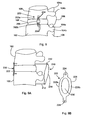
- FIG. 6B is a partial side view of a prosthetic facet and facet joint assembly.
- FIGS. 6C and 6D are front and side views of a prosthetic facet and facet joint assembly.
- FIG. 7 is an illustration of a portion of a spinal column with a prosthetic facet and facet joint assembly having a pair of prosthetic facet joints.
- FIG. 8 is a lateral view of a pair of vertebral bodies having a lateral stabilization device implanted between them.
- FIG. 9A is a lateral view of a pair of vertebral bodies having an anterior stabilization device and a posterior stabilization device.
- FIG. 9B is an illustration of an anterior stabilization device.
- FIG. 10A is an illustration of a spacer member.
- FIGS. 10B-D are illustrations of posterior dynamic stabilization devices including a spacer member and restrictor bands both as implanted on the spine and isolated from the spine.
- FIG. 11 is a posterior view of another dynamic stabilization system.
- FIG. 12A is a posterior, schematic view of a dynamic stabilizer traversing two adjoining discs.
- FIGS. 12B and 12C are, respectively, front and side views of one element of the dynamic stabilizer shown in FIG. 12A .
- FIG. 12D shows the end of the element shown in FIGS. 12B and 12C .
- FIGS. 12E to 12F show movement of the elements during rotation of the spine.
- FIG. 13A is a side view of another dynamic stabilization system.
- FIG. 13B is a schematic showing rotation and reaction when the FIG. 13A device is deployed.
- FIG. 14 is a posterior view of another dynamic stabilization system.
- FIG. 15 is a lateral view of another dynamic stabilization system.
- FIG. 16 is a lateral view of another dynamic stabilization system.
- FIG. 17 is a lateral view of another dynamic stabilization system.
- FIG. 18 is a perspective, cross-sectional view of one example of a prosthetic intervertebral disc.
- FIG. 1 illustrates a pair of adjacent vertebrae, including a superior or upper vertebral body ( 100 ) and an inferior or lower vertebral body ( 102 ).
- Upper vertebral body ( 100 ) includes a pair of transverse processes ( 104 a , 104 b ) and a spinous process ( 106 ) extending generally posteriorly.
- Lower vertebral body ( 102 ) includes a pair of transverse processes ( 105 a , 105 b ) and a spinous process ( 107 ).
- a disc ( 108 ) is located between the superior vertebral body ( 100 ) and the inferior vertebral body ( 102 ).
- the spinal cord ( 110 ) extends through a central passage formed by the spinal column, and nerve roots ( 112 ) transverse the foramenal space ( 114 ) defined by the pair of vertebral bodies.
- the superior vertebral body ( 100 ) and inferior vertebral body ( 102 ) tend to collapse upon each other, thereby decreasing the amount of space formed by the foramen ( 114 ). This result also commonly occurs when the vertebral bodies are afflicted with disease or are fractured or otherwise damaged.
- the vertebral bodies ( 100 , 102 ) may impinge upon the nerve root ( 112 ), causing discomfort, pain, and possible damage to the nerve root.
- the foramenal spacers described herein are intended to alleviate this problem by maintaining the foramenal opening and otherwise protecting the nerve root from impingement by the vertebral bodies.
- the foramenal spacer ( 120 ) includes a pair of C-shaped members ( 122 , 124 ).
- the C-shaped members may include an attachment mechanism or mating surfaces.
- one C-shaped member ( 122 ) includes a groove or notch ( 126 ) on each of its inferior-facing surfaces ( 128 )
- the other C-shaped member ( 124 ) includes a mating tab ( 130 ) on each of its superior-facing surfaces ( 132 ).
- the tabs and notches may be alternated, one on one member and one on the other.
- the mating surfaces ( 128 , 132 ) may simply butt up against one another to form a butt-joint that prevents collapse of the foramenal space.
- the pair of C-shaped members ( 122 , 124 ) define a generally disc-shaped member ( 134 ) having a central through-hole ( 136 ).
- the central through-hole ( 136 ) has a size and shape suitable for passage of nerve root ( 112 ) without impingement as shown, for example, in FIGS. 2C and 2D .
- the foramenal spacer ( 120 ) may be provided with an outer layer ( 140 ) that includes a coating of a soft, conformable material.
- the outer layer ( 140 ) may cover all of the external-facing surfaces of the foramenal spacer ( 120 ), and particularly those that are positioned to engage the vertebral body surfaces.
- the outer layer ( 140 ) may comprise a soft, conformable biocompatible material such as silicone, polyurethane, or other similar polymeric materials.
- the outer layer ( 140 ) helps to provide structural protection to the vertebral bodies forming the foramenal space, and also allows the foramenal spacer ( 120 ) to adapt to the varying foramenal geometries formed by the vertebral bodies.
- An optional inner layer or liner ( 142 ) may be provided on the exposed surfaces defining the through-hole ( 136 ) of a coating of soft and/or low-friction material to provide an atraumatic surface for passage of the nerve root ( 112 ).
- the inner layer or liner ( 142 ) may comprise the materials similar to those used for the outer layer ( 140 ).
- the inner layer or liner ( 142 ) may comprise a coating of lubricious materials such as polyethylene, PTFE, or other similar material.
- an optional spring member, gasket, cushion, or other similar material or device may be interposed between the two C-shaped members ( 122 , 124 ).
- the spring member or the like
- the spring member may be located between the abutting surfaces of the two C-shaped members. This spring member (or the like) expands the spacer ( 120 ) with as the spring member extends and compresses, thereby providing a range of motion for supporting the foramenal space.
- FIG. 2F shows a variation of our foramenal spacer.
- the foramenal spacer ( 120 ) includes a first segment ( 150 ) and a second (or inner) segment ( 156 ).
- the first segment ( 150 ) includes an external surface ( 152 ) that has a shape suitable for engaging the portion of a vertebral body defining the foramenal space ( 114 ).
- the other segment ( 156 ) includes an external surface ( 158 ) that has a shape adapted to engage a portion of the adjoining vertebral body defining the foramenal space ( 114 ).
- An internal surface ( 154 ) of the first segment ( 150 ) includes a curved portion that rotatably engages a mating curved portion of the external surface ( 158 ) of segment ( 156 ).
- the segments ( 150 , 152 ) are rotationally connected to one another, i.e., the segments ( 150 , 152 ) function similarly to a bearing having a center of rotation.
- the foramenal spacer ( 120 ) allows the two vertebral bodies to pivot relative to one another, thereby providing an additional range of motion.
- the foramenal spacer ( 120 ) shown in FIG. 2F may also include an outer layer ( 140 ) and an inner layer or liner ( 142 ) described above in relation to FIG. 2E .
- the foramenal spacer ( 120 ) may be implanted by any appropriate surgical technique, including accessing the foramenal space by either a posterior approach or a lateral approach.
- the lateral approach is believed to provide optimal access for exposure of the foramen, but techniques for posterior lumbar interbody fusion (PLIF) and transforamenal lumbar interbody fusion (TLIF) also provide sufficient access.
- PLIF posterior lumbar interbody fusion
- TLIF transforamenal lumbar interbody fusion
- the foramenal spacer ( 120 ) is attached to the pedicle or other anatomic structure that allows extension of the spacer into the foramenal space ( 114 ).
- the foramenal spacer ( 120 ) may be press fit into the foramen ( 116 ).
- FIG. 2G shows a foramenal spacer ( 120 ) having a tab ( 157 ) with an opening ( 159 ) for attaching the foramenal spacer ( 120 ) to the
- FIG. 3 a posterior view of a pair of adjacent vertebral bodies is shown.
- the Figures illustrates a superior vertebral body ( 100 ) and an inferior vertebral body ( 102 ).
- Each vertebral body includes a pair of transverse processes ( 104 a - b and a spinous process ( 106 ) extending generally posteriorly from each vertebral body ( 100 , 102 ).
- the spinal cord ( 110 ) extends through a central passage formed by the spinal column, and nerve roots ( 112 ) transverse the foramenal space ( 114 ) defined by the pair of vertebral bodies.
- a facet joint ( 118 ) is formed by a pair of facing facets, one each from the superior and inferior vertebral bodies.
- FIG. 4 shows a facet stabilizing member ( 170 ).
- the facet stabilizing member ( 170 ) preferably includes a core member ( 172 ) encased in a jacket ( 174 ).
- the core member ( 172 ) may comprise a hydrogel, gel, elastomer, polyurethane, or other polymeric material suitable for providing the shock absorbing and spacing functions necessary to stabilize the facet joint.
- the jacket ( 174 ) may be a fabric (woven or unwoven) of biocompatible material and is intended to maintain the integrity and shape of the core member ( 172 ) and to otherwise provide structural strength to the facet stabilizing member ( 170 ).
- the facet stabilizing member ( 170 ) has a size and shape suitable for placement in the facet joint ( 118 ) and provide stabilization to the joint and to prevent collapse of the foramenal space.
- FIG. 5 shows another variation of our facet stabilizing member ( 170 ).
- the depicted spinal stabilizing member ( 170 ) includes an upper endplate ( 180 ), a lower endplate ( 182 ), and a core member ( 184 ) extending between and interconnecting the upper endplate ( 180 ) and lower endplate ( 182 ).
- the facet stabilizing member also includes a plurality of fibers ( 186 ) wound between and interconnecting the upper endplate ( 180 ) and lower endplate ( 182 ).
- the construction and materials of the facet stabilizing member ( 170 ) shown in FIG. 5 are similar to the construction and materials of the prosthetic intervertebral disc described below in relation to FIG.
- prosthetic intervertebral discs described in U.S. patent application Ser. No. 10/903,276, filed Jul. 30, 2004, and U.S. Provisional Application Ser. No. 60/713,671, filed Sep. 1, 2005, each of which is incorporated by reference.
- Other prosthetic disc constructions as described in the foregoing applications are also suitable for use in the facet stabilizing members ( 170 ) described herein.
- the size of the facet stabilizing member ( 170 ) is typically smaller than the sizes of the prosthetic discs described in the foregoing applications, but the overall construction of the structure may be the same.
- the facet stabilizing member ( 170 ) is implanted between the pair of opposed facets associated with the pair of adjacent vertebral bodies. Additional features, such as fins, fixation members, or other structures (not shown), may also be incorporated on the facet stabilizing member ( 170 ) to limit movement.
- the facet joint is synovial; implantation may be performed through the capsule. Access to the facet joint may be obtained by any of the methods described above in relation to implantation of the foramenal spacer.
- FIGS. 6A to 7 shows several variations of our prosthetic facet and facet joint assemblies. These assemblies are particularly useful in repairing spinal structure compromised, e.g., during spinal surgical procedures, particularly those including approach by the posterior, where some of or the entire facet is removed to implant one or more prosthetic structures.
- the devices are similarly suitable in cases where the facets or facet joints are damaged through trauma, disease, or other disorder to stabilize to the effected spinal segments.
- FIG. 6A shows a number of combination prosthetic facet and facet joint assemblies ( 190 ) implanted in several locations on a spinal column.
- the native facet and facet joint is removed prior to implanting the prosthetic assembly.
- Each depicted prosthetic facet assembly ( 190 ) includes an upper attachment arm ( 192 ) that, as may be seen in the side view of FIG. 6D , is generally elongated and curved forward to match the shape and structure of the prepared native facet.
- the depicted upper attachment arm ( 192 ) is attached to or terminates in an endplate ( 194 ) forming a portion of a facet stabilizing member ( 170 ).
- the upper attachment arm ( 192 ) is attached to its associated vertebral body by appropriate fasteners, e.g., one or more screws ( 196 ).
- the facet stabilizing member ( 170 ) may be similar in construction and materials of construction to those described above in relation to the FIG. 5 , above.
- the assembly ( 190 ) also includes a lower attachment arm ( 193 ) that is also generally elongated and curved rearward (again, as seen in the side view of FIG. 6D ) to match the shape and conform to the structure of the prepared native facet on the lower vertebral body.
- the facet stabilizing member ( 170 ) is interposed between a pair of prosthetic facets ( 190 , 193 ) with the facet endplates ( 194 ) serving as the endplates for the facet stabilizing member ( 170 ). (See, in particular, FIG. 6B ).
- the facet stabilizing member ( 170 ) is sized and oriented with respect to the prosthetic facets ( 190 , 193 ) to approach several physical parameters of the facet joint that has been removed.
- the facet stabilizing member ( 170 ) is generally oriented with respect to the prosthetic facets ( 190 , 193 ) so that it matches or approaches the orientation of the native facet joint with respect to the respective vertebrae.
- the orientation of combination prosthetic facet and facet joint assembly ( 190 ) and its included facet stabilizing member ( 170 ) is different for each facet site on the spine.
- the combination prosthetic facet and facet joint assemblies ( 190 ) are implanted in matching (mirror image) pairs on each side of a vertebral body to assure conforming performance.
- FIG. 7 illustrates a multi-level stabilization assembly ( 195 ) having prosthetic facets and facet joints.
- the assembly ( 195 ) extends over several adjacent vertebral segments using several facet stabilizing members ( 170 ).
- the depicted assembly ( 195 ) includes an elongated lower attachment arm ( 193 ) that is curved rearward to match the shape and conform to the structure of the prepared site on the sacrum ( 119 ).
- the assembly ( 195 ) also includes an elongated upper attachment arm ( 192 ) that is curved rearward to match the shape and conform to the structure of the prepared site on the uppermost vertebrae ( 199 ), shown as the L-4 vertebra in the drawing.
- a double-ended mid-attachment member ( 197 ) that serves to connect the two facet stabilizing members ( 170 ), the mid-vertebra ( 201 ) or L-5, and indirectly through the two facet stabilizing members ( 170 ), lower attachment arm ( 193 ) and the upper attachment arm ( 192 ).
- the native facets and associated facet joints would be removed prior to the implantation of the multi-level stabilization assembly ( 195 ).
- a pair of mirror-image multi-level stabilization assemblies ( 195 ) would be a desirable implantation choice.
- FIG. 8 shows a lateral stabilization device ( 200 ) having an upper attachment arm ( 202 a ) attached to a superior vertebral body ( 100 ) by one or more fasteners, e.g., screws ( 204 ), and a lower attachment arm ( 202 b ) attached to an inferior vertebral body ( 102 ) by one or more fasteners, such as screws ( 204 ).
- the device also includes a stabilization member ( 206 ).
- the stabilization member ( 206 ) may include a spring or springs, a damper, or other mechanism that provides a desired stabilization function.
- the stabilization member may comprise a structure such as the facet stabilization member ( 170 ) described above in relation to FIGS. 6A to 7 above.
- Our lateral stabilization device ( 200 ) may be attached to the lateral surfaces of two adjacent vertebral bodies ( 100 , 102 ). For assurance of balanced response to spine motion, a pair of lateral stabilization devices ( 200 ) may be attached, one on each lateral side of the pair of vertebral bodies.
- FIG. 9A shows a pair of adjacent vertebral bodies ( 100 , 102 ) having both a posterior stabilization device ( 210 ) and an anterior stabilization device ( 220 ) attached to each of the pair of vertebral bodies.
- the posterior stabilization device ( 210 ) includes a pair of studs or pedicle screws ( 212 ), one attached to each of the superior vertebral body ( 100 ) and to the inferior vertebral body ( 102 ).
- a stabilization member ( 214 ) extends between and interconnects the pair of pedicle screws ( 212 ).
- the stabilization member ( 214 ) may comprise a load bearing dynamic structure comprising a spring or springs, one or more dampers (damping in either or both axial directions), or any combination of such structures.
- the anterior stabilization device ( 220 ) includes an anterior element ( 222 ), shown in isolation in FIG. 9B .
- the anterior element ( 222 ) may comprise a material having superelastic properties, e.g., nitinol or the like. It may be of a shape that allows the anterior element ( 222 ) to be constrained for a minimally invasive implantation procedure.
- the anterior element ( 222 ) includes an attachment hole ( 224 ) at each end, and a central portion ( 226 ) that includes a pair of side bands ( 228 a , 228 b ) that define a central aperture ( 230 ).
- the anterior element ( 222 ) may be rolled or compressed into a low profile contracted state for implantation. Once introduced, the anterior element is partially released from the contracted state and attached to the pair of vertebral bodies ( 100 , 102 ) adjacent to the damaged disc ( 108 ).
- the anterior element ( 222 ) may be attached by fasteners, such as screws or other suitable mechanisms. Once attached, the anterior element ( 222 ) is fully extended to its operative state and is capable of bearing loads to stabilize the vertebral segments.
- the anterior stabilization device ( 220 ) may be used alone, in combination with the posterior stabilization device ( 210 ) illustrated in FIG. 9A , or in combination with any other suitable stabilization device or structure.
- the amounts and types of stabilization and unloading of the vertebral segment may be tailored to suit a specific clinical situation in a way that may be may not be readily possible using a single stabilization structure.
- FIGS. 10A-D show several variations of a posterior dynamic stabilization system made up, in general, of a posterior spacer and one or more restrictor bands.
- the spacer may be integrated with the restrictor bands, or it may be provided independently of the restrictor bands.
- FIG. 10A shows a posterior spacer ( 240 ) that is generally in the shape of a short cylinder or bead, having a central through-hole ( 242 ) and an upper surface ( 244 ) and lower surface ( 246 ).
- the posterior spacer ( 240 ) may be designed in other forms or shapes, as is described more fully below.
- the spacer ( 240 ) may comprise a generally compliant biocompatible material, e.g., polymeric materials such as polyurethanes, silicones, TPE's, and other elastomers, or other suitable polymeric material. As shown in the posterior view found in FIGS.
- the spacer ( 240 ) is placed between the spinous processes ( 106 ) of a pair of adjacent vertebral bodies ( 100 , 102 ).
- the spacer ( 240 ) maintains the spacing between the vertebral bodies while allowing a desired amount of relative motion between the two vertebral bodies.
- the restrictor band ( 250 ) may be a continuous loop and may comprise a relatively elastic biocompatible material, such as any number of elastomeric and/or polymeric materials suitable for the purpose. Should a constrained motion be desired, the loops may be a comparatively inelastic material, e.g., nitinol or other such biocompatible alloys.
- the restrictor bands ( 250 ) are linked to the posterior spine to provide both stability and compliance.
- the bands ( 250 ) may be attached to the vertebra by suitable fasteners, e.g., attachment screws ( 252 ) or studs or the like.
- FIGS. 10 B 2 and 10 C 2 show the spacer ( 240 ) and the routing of the bands ( 250 ) through the center opening ( 242 ) in the spacer. These drawings are provided to show that routing in isolation from the spine; the same configuration is shown respectively in FIGS. 10 B 1 and 10 C 1 .
- FIG. 10D shows attachment of the bands ( 250 ) by looping them directly onto the spinous processes ( 106 ) of the pair of vertebral bodies.
- the materials, sizes, structures, and routing of the restrictor bands ( 250 ) may be chosen to tailor a desired type and degree of constraint. For example, a routing pattern that is oriented relatively more diagonally to the axis of the spine, as in FIG. 10 C 1 , will provide more resistance to torsional movement than will a routing pattern that is oriented more vertically, as is shown in FIG. 10D .
- FIG. 11 shows another variation of a dynamic spinal stabilization device having the capability of being adjusted after implantation.
- the illustrated spinal stabilization device ( 260 ) includes an upper attachment member ( 262 ) and a lower attachment member ( 264 ), for attachment to a superior vertebral body ( 100 ) and an inferior vertebral body ( 102 ), respectively.
- the two attachment members ( 262 , 264 ) may be attached to the spinous processes ( 106 ) of the respective vertebral bodies ( 100 , 102 ), as shown, or attached to the pedicles or to other suitable portions of the vertebral bodies.
- the attachment members ( 262 , 264 ) may utilize or comprise screws, although other attachment members may be used as desired or as suitable.
- the stabilization device ( 260 ) includes one or more spring elements ( 266 ) that each extend between and interconnect the upper attachment member ( 262 ) and the lower attachment member ( 264 ).
- Each spring element ( 266 ) is may be formed of a suitable biocompatible shape memory or superelastic material, such as nitinol. If the proper alloy is chosen, e.g., by utilizing nitinol having A t ⁇ 100° F., the shape and properties of each spring element ( 266 ) may be altered after implantation by heating the spring element, for example, using an electric current. Obviously, in such a situation, the spring elements may also be altered prior to implantation.
- the shape memory material may be trained by a heating process to conform to a predetermined shape upon being heated to a predetermined temperature.
- leads may be placed in contact with the spring elements ( 266 ) under X-ray or other guidance after implantation in the spine of a patient. Electric current is then supplied to the spring elements ( 266 ) through the leads, allowing the user to alter the size, shape, or performance characteristics of the spring elements.
- spring elements ( 266 ) shown in the embodiment illustrated in FIG. 11 are depicted as generally straight struts, the spring elements ( 266 ) may have other shapes, sizes, or orientations suitable for a given application.
- FIG. 12A is a schematic representation of another spinal stabilization device that transfers loads from one segment of the spine to adjacent segments.
- Three adjacent vertebral bodies ( 270 , 272 , 274 ) are shown schematically in the Figure.
- a pair of interconnected stabilization devices ( 276 ) are attached to each of the three vertebral bodies.
- the stabilization devices ( 276 ) are elongate and fairly stiff but include shock absorption and spring providing features in the linkages ( 280 ).
- Each depicted stabilization device ( 276 ) includes three fixed rotatable elements ( 278 ), each attached to a vertebral body through a bone fixation device or member, e.g., a threaded stud or pedicle screw, and includes a linkages ( 280 ) extending between and attached to each adjacent pair of fixed rotatable elements ( 278 ).
- a bone fixation device or member e.g., a threaded stud or pedicle screw
- Each of the fixed rotatable elements ( 278 ) comprises a bearing structure ( 279 in FIG. 12D ) or similar mechanism that allows rotation of the attached linkage ( 280 ).
- the depicted bearing structures ( 279 ) are often known as Heim joints. This allows a first vertebral segment, such as vertebral body ( 270 ), to be loaded in reaction to a load placed upon the adjacent vertebral segments, such as vertebral bodies ( 272 ) and ( 274 ).
- each of the fixation elements ( 278 ) may include a bearing or similar rotatable structure ( 279 ) that allows rotational movement as represented by the arrows “C”. This motion transfer is seen from the side in schematic FIG. 12E and from the top in FIG. 12F .
- the linkages ( 280 ) may comprise a compressible element and spring element or elements having a size, shape, spring constant, and other characteristics that provide the desired amount of load transfer in response to rotation of the fixation elements ( 278 ).
- two stabilization devices ( 276 ) are shown in the Figures, more or fewer devices may be used depending upon the degree of stabilization needed or desired.
- the stabilization devices ( 276 ) may also extend between more (e.g., four or more) or fewer (e.g., two) adjacent vertebral segments.
- FIG. 13A shows a multi-component dynamic stabilization system.
- Current dynamic spinal stabilization systems are typically either interspinous devices (i.e., connected between the spinous processes of adjacent vertebral bodies) or pedicle screw based devices (i.e., connected between pedicle screws attached to the pedicles of adjacent vertebral bodies). Each of these types of dynamic stabilization devices functions by providing a distracting force that unloads the disc ( 108 ).
- FIG. 13A shows a multi-component dynamic stabilization system.
- Current dynamic spinal stabilization systems are typically either interspinous devices (i.e., connected between the spinous processes of adjacent vertebral bodies) or pedicle screw based devices (i.e., connected between pedicle screws attached to the pedicles of adjacent vertebral bodies).
- pedicle screw based devices i.e., connected between pedicle screws attached to the pedicles of adjacent vertebral bodies.
- FIG. 13A shows an interspinous stabilization system ( 290 ) connected to the spinous processes ( 106 ) of a pair of adjacent vertebral bodies ( 100 , 102 ), and a pair of pedicle based stabilization systems ( 292 a , 292 b ) (only one of the pedicle based systems is shown in the Figure) attached by pedicle screws to the pair of adjacent vertebral bodies ( 100 , 102 ) on each side of the spinous processes.
- Each of the pedicle based systems ( 292 a , 292 b ) comprises a spring loaded or other suitable structure that provides a distracting force (arrows “D” in FIG. 13B ), that tends to unload the disc ( 108 ).
- the interspinous system ( 290 ) includes a spring loaded or other suitable structure that biases the spinous processes ( 106 ) of the adjacent vertebral bodies ( 100 , 102 ) toward one another, as represented by arrows “E” in FIG. 13B .
- the combined action of the interspinous system ( 290 ) and the pedicle based systems ( 292 a , 292 b ) creates a moment that relieves pressure from the disc ( 108 ).
- the interspinous system ( 290 ) and the pedicle based systems ( 292 a , 292 b ) shown in FIGS. 13A and 13B may be constructed such that one or more of the systems is externally adjustable, as described, for example, below.
- FIG. 14 shows a rear view of a pair of adjacent vertebral bodies ( 100 , 102 ) having dynamic stabilization devices ( 300 ) attached to each of the vertebral bodies at a position at or near the transverse processes ( 104 a , 104 b ) of each vertebral body ( 100 , 102 ).
- Each dynamic stabilization device ( 300 ) includes an upper attachment screw ( 302 ) and a lower attachment screw ( 304 ).
- the screws ( 302 , 304 ) may be placed through the transverse process to the vertebral body, or they may be attached directly to the vertebral body adjacent the transverse process ( 104 a , 104 b ).
- a loading member ( 306 ) is attached to each of the upper attachment screw ( 302 ) and the lower attachment screw ( 304 ) . . . .
- the loading member ( 306 ) stabilizes the adjacent vertebral bodies by providing an appropriate level of distraction or attraction forces.
- the loading member ( 306 ) may comprise a spring, a set of springs, a damping member, or any other suitable structure such as those described elsewhere herein.
- FIG. 15 provides a schematic illustration of an externally adjustable dynamic stabilization system.
- the system includes an upper screw ( 310 ) and lower screw ( 312 ) extending posteriorly from an upper vertebral body ( 100 ) and a lower vertebral body ( 102 ), respectively. Each screw extends outside of the patient's body.
- a stabilization member ( 314 ) is attached to each of the screws ( 310 , 312 ) on the external surface of the patient's back, i.e., outside the surface of the skin ( 316 ).
- the stabilization member ( 314 ) may include a spring or springs, dampers (damping in one axial direction, the other direction, or both),
- the stabilization system ( 316 ) may be adjusted post-operatively because it is located externally of the patient without the need for additional surgical intervention.
- FIG. 16 is a schematic illustration of another adjustable stabilization system.
- the spinal stabilization system ( 320 ) includes an upper pot ( 322 ) attached to the spinous process ( 106 ) of a superior vertebral body ( 100 ), and a lower pot ( 324 ) attached to the spinous process ( 106 ) of an inferior vertebral body ( 102 ).
- Each of the upper pot ( 322 ) and lower pot ( 324 ) forms a portion of the attachment mechanism for the stabilization device.
- the upper pot ( 322 ) and lower pot ( 324 ) may be attached to the spinous processes ( 106 ) by any suitable mechanism, such as one or more screws.
- Each of the upper pot ( 322 ) and lower pot ( 324 ) includes a cylindrical portion that is adapted to receive a connector ( 326 ) located at each of the upper end and lower end of a spring ( 328 ).
- Each of the connectors ( 326 ) engages one of the upper pot ( 322 ) and lower pot ( 324 ), thereby allowing the spring ( 328 ) to provide a distracting force to the vertebral bodies ( 100 , 102 ).
- the upper pot ( 322 ) and lower pot ( 324 ) are generally hollow, it is possible to partially fill one or both of the pots ( 322 , 324 ) to decrease the effective length of the spring ( 328 ) extending between the pots, i.e., partially filling the pots causes the connectors to engage the filler material at a level removed from the bottom of the pot ( 322 , 324 ).
- Either or both of the pots ( 322 , 324 ) may be partially filled with bone cement containing polymethylmethacrylate (PMMA) or another suitable material. The filling operation may be performed post-operatively by way of a percutaneous access, thereby eliminating the need for additional surgical intervention.
- PMMA polymethylmethacrylate
- the spacer ( 342 ) is a silicone device covered with polyethylene, and functions by reducing loading of the disc, restoring the posterior tension band, realigning the facets, and restoring the foramenal height.
- a stabilizing disc ( 344 ) is interposed between the spinous processes ( 106 ) in place of a portion of the spacer ( 340 ).
- the stabilizing disc ( 344 ) has a structure and is constructed in a manner identical to the facet stabilizing member ( 170 ) described above in relation to FIG. 5 , having a core member located between a pair of endplates.
- the stabilizing disc ( 344 ) allows for compression and rotation, if needed.
- the stabilizing disc ( 344 ) also facilitates lateral bending.
- FIG. 18 an exemplary prosthetic intervertebral disc ( 1100 ) is shown in FIG. 18 , which is reproduced from FIG. 3 of the '671 application and which was also described in the '276 application.
- This prosthetic disc is described for exemplary purposes, and is not intended to represent the only type of prosthetic disc that is suitable for use in combination with the devices and systems described elsewhere herein.
- the prosthetic disc ( 1100 ) has an integrated structure that includes an upper endplate ( 1110 ), a lower endplate ( 1120 ), and a core member ( 1130 ) retained between the upper endplate ( 1110 ) and the lower endplate ( 1120 ).
- One or more fibers ( 1140 ) are wound around the upper and lower endplates to attach the endplates to one another.
- the wind of the fibers ( 1140 ) allows a degree of axial rotation, bending, flexion, and extension by and between the endplates.
- An annular capsule ( 1150 ) is optionally provided in the space between the upper and lower endplates, surrounding the core member ( 1130 ) and the fibers ( 1140 ).
- the upper endplate ( 1110 ) and lower endplate ( 1120 ) are generally flat, planar members, and are fabricated from a biocompatible material that provides substantial rigidity.
- the upper surface of the upper endplate ( 1110 ) and the lower surface of the lower endplate ( 1120 ) are preferably each provided with a mechanism for securing the endplate to the respective opposed surfaces of the upper and lower vertebral bodies between which the prosthetic disc is to be installed.
- the upper endplate ( 1110 ) includes a plurality of anchoring fins ( 1111 a , 1111 b ).
- the anchoring fins ( 1111 a , 1111 b are intended to engage mating grooves that are formed on the surfaces of the upper and lower vertebral bodies to thereby secure the endplate to its respective vertebral body.
- the anchoring fins ( 1111 a , 1111 b ) extend generally perpendicularly from the generally planar external surface of the upper endplate ( 1110 ), i.e., upward from the upper side of the endplate as shown in FIG. 18 .
- Each of the anchoring fins ( 1111 a , 1111 b ) has a plurality of serrations ( 1112 ) located on the top edge of the anchoring fin.
- the serrations ( 1112 ) are intended to enhance the ability of the anchoring fin to engage the vertebral body and to thereby secure the upper endplate ( 1110 ) to the spine.
- the lower surface of the lower endplate ( 1120 ) includes a plurality of anchoring fins ( 1121 a , 1111 b ).
- the anchoring fins ( 1121 a , 1111 b ) on the lower surface of the lower endplate ( 1120 ) are identical in structure and function to the anchoring fins ( 1111 a , 1111 b ) on the upper surface of the upper endplate ( 1110 ), with the exception of their location on the prosthetic disc.
- the anchoring fins ( 1111 , 1121 ) may optionally be provided with one or more holes or slots ( 1115 , 1125 ).
- the holes or slots help to promote bony ingrowth that assist in anchoring the prosthetic disc ( 1100 ) to the vertebral bodies.
- the core member ( 1130 ) is intended to provide support to and to maintain the relative spacing between the upper endplate ( 1110 ) and lower endplate ( 1120 ).
- the core member ( 1130 ) is made of a relatively compliant material, for example, polyurethane or silicone, and is typically fabricated by injection molding.
- a preferred construction for the core member includes a nucleus formed of a hydrogel and an elastomer reinforced fiber annulus.
- the shape of the core member ( 1130 ) is typically generally cylindrical or bean-shaped, although the shape (as well as the materials making up the core member and the core member size) may be varied to obtain desired physical or performance properties.
- the core member ( 1130 ) shape, size, and materials of construction will directly affect the degree of flexion, extension, lateral bending, and axial rotation of the prosthetic disc.
- prosthetic disc ( 1100 ), or other suitable prosthetic discs may be implanted by surgical techniques described in the '671 and '276 applications and elsewhere. As described above, it may be advantageous to combine the prosthetic intervertebral disc with any of the devices, systems, and methods described herein to obtain synergistic therapeutic results in treatment of spinal disease, trauma, or other disorder.
Abstract
Description
Claims (6)
Priority Applications (1)
| Application Number | Priority Date | Filing Date | Title |
|---|---|---|---|
| US12/927,208 US9597125B2 (en) | 2005-09-23 | 2010-11-08 | Prosthetic facet and facet joint replacement device |
Applications Claiming Priority (3)
| Application Number | Priority Date | Filing Date | Title |
|---|---|---|---|
| US11/234,481 US20070083200A1 (en) | 2005-09-23 | 2005-09-23 | Spinal stabilization systems and methods |
| US11/540,044 US20070167947A1 (en) | 2005-09-23 | 2006-09-29 | Spinal stabilization device |
| US12/927,208 US9597125B2 (en) | 2005-09-23 | 2010-11-08 | Prosthetic facet and facet joint replacement device |
Related Parent Applications (1)
| Application Number | Title | Priority Date | Filing Date |
|---|---|---|---|
| US11/540,044 Continuation US20070167947A1 (en) | 2005-09-23 | 2006-09-29 | Spinal stabilization device |
Publications (2)
| Publication Number | Publication Date |
|---|---|
| US20110093012A1 US20110093012A1 (en) | 2011-04-21 |
| US9597125B2 true US9597125B2 (en) | 2017-03-21 |
Family
ID=37900215
Family Applications (6)
| Application Number | Title | Priority Date | Filing Date |
|---|---|---|---|
| US11/234,481 Abandoned US20070083200A1 (en) | 2005-09-23 | 2005-09-23 | Spinal stabilization systems and methods |
| US11/540,044 Abandoned US20070167947A1 (en) | 2005-09-23 | 2006-09-29 | Spinal stabilization device |
| US11/529,849 Active US7803189B2 (en) | 2005-09-23 | 2006-09-29 | Prosthetic facet and facet joint replacement device |
| US12/789,033 Abandoned US20100234951A1 (en) | 2005-09-23 | 2010-05-27 | Prosthetic facet and facet joint replacement device |
| US12/927,208 Active 2029-02-24 US9597125B2 (en) | 2005-09-23 | 2010-11-08 | Prosthetic facet and facet joint replacement device |
| US15/530,859 Abandoned US20170325853A1 (en) | 2005-09-23 | 2017-03-09 | Prosthetic facet and facet joint replacement device |
Family Applications Before (4)
| Application Number | Title | Priority Date | Filing Date |
|---|---|---|---|
| US11/234,481 Abandoned US20070083200A1 (en) | 2005-09-23 | 2005-09-23 | Spinal stabilization systems and methods |
| US11/540,044 Abandoned US20070167947A1 (en) | 2005-09-23 | 2006-09-29 | Spinal stabilization device |
| US11/529,849 Active US7803189B2 (en) | 2005-09-23 | 2006-09-29 | Prosthetic facet and facet joint replacement device |
| US12/789,033 Abandoned US20100234951A1 (en) | 2005-09-23 | 2010-05-27 | Prosthetic facet and facet joint replacement device |
Family Applications After (1)
| Application Number | Title | Priority Date | Filing Date |
|---|---|---|---|
| US15/530,859 Abandoned US20170325853A1 (en) | 2005-09-23 | 2017-03-09 | Prosthetic facet and facet joint replacement device |
Country Status (8)
| Country | Link |
|---|---|
| US (6) | US20070083200A1 (en) |
| EP (3) | EP1937166A4 (en) |
| JP (1) | JP2009508633A (en) |
| CN (1) | CN101351160A (en) |
| AU (1) | AU2006295188A1 (en) |
| BR (1) | BRPI0616403A2 (en) |
| CA (1) | CA2623524A1 (en) |
| WO (1) | WO2007037920A2 (en) |
Families Citing this family (88)
| Publication number | Priority date | Publication date | Assignee | Title |
|---|---|---|---|---|
| US7282064B2 (en) * | 2003-02-11 | 2007-10-16 | Spinefrontier Lls | Apparatus and method for connecting spinal vertebrae |
| US7588590B2 (en) | 2003-12-10 | 2009-09-15 | Facet Solutions, Inc | Spinal facet implant with spherical implant apposition surface and bone bed and methods of use |
| US8333789B2 (en) | 2007-01-10 | 2012-12-18 | Gmedelaware 2 Llc | Facet joint replacement |
| US8998952B2 (en) * | 2004-02-17 | 2015-04-07 | Globus Medical, Inc. | Facet joint replacement instruments and methods |
| US8562649B2 (en) | 2004-02-17 | 2013-10-22 | Gmedelaware 2 Llc | System and method for multiple level facet joint arthroplasty and fusion |
| US8523904B2 (en) | 2004-03-09 | 2013-09-03 | The Board Of Trustees Of The Leland Stanford Junior University | Methods and systems for constraint of spinous processes with attachment |
| US7588578B2 (en) | 2004-06-02 | 2009-09-15 | Facet Solutions, Inc | Surgical measurement systems and methods |
| US8114158B2 (en) | 2004-08-03 | 2012-02-14 | Kspine, Inc. | Facet device and method |
| US20070083200A1 (en) * | 2005-09-23 | 2007-04-12 | Gittings Darin C | Spinal stabilization systems and methods |
| WO2007134113A2 (en) * | 2006-05-09 | 2007-11-22 | Raymedica, Llc | Systems and methods for stabilizing a functional spinal unit |
| US20080071379A1 (en) * | 2006-05-10 | 2008-03-20 | Mark Rydell | Intervertebral disc replacement |
| US8337528B2 (en) * | 2006-11-28 | 2012-12-25 | Anova Corporation | Methods and apparatus for stabilizing a spinal segment |
| US8172882B2 (en) | 2006-06-14 | 2012-05-08 | Spartek Medical, Inc. | Implant system and method to treat degenerative disorders of the spine |
| US20080033433A1 (en) * | 2006-08-01 | 2008-02-07 | Dante Implicito | Dynamic spinal stabilization device |
| US8162982B2 (en) | 2006-10-19 | 2012-04-24 | Simpirica Spine, Inc. | Methods and systems for constraint of multiple spine segments |
| US8187307B2 (en) * | 2006-10-19 | 2012-05-29 | Simpirica Spine, Inc. | Structures and methods for constraining spinal processes with single connector |
| JP2010506693A (en) * | 2006-10-19 | 2010-03-04 | シンピライカ スパイン, インコーポレイテッド | Structure and method for constraining spinous processes using a single connector |
| US8029541B2 (en) * | 2006-10-19 | 2011-10-04 | Simpirica Spine, Inc. | Methods and systems for laterally stabilized constraint of spinous processes |
| US20080262549A1 (en) * | 2006-10-19 | 2008-10-23 | Simpirica Spine, Inc. | Methods and systems for deploying spinous process constraints |
| US8109978B2 (en) * | 2006-11-28 | 2012-02-07 | Anova Corporation | Methods of posterior fixation and stabilization of a spinal segment |
| US8162993B2 (en) * | 2006-11-28 | 2012-04-24 | Anova Corporation | Methods of anterior fixation and stabilization of a spinal segment |
| US8075596B2 (en) | 2007-01-12 | 2011-12-13 | Warsaw Orthopedic, Inc. | Spinal prosthesis systems |
| US8337529B2 (en) * | 2007-02-13 | 2012-12-25 | Anova Corp. | Methods of bone, joint, and ligament reconstruction |
| EP1994901A1 (en) * | 2007-05-24 | 2008-11-26 | Bio Medical S.r.L. | Intervertebral support device |
| US8070779B2 (en) * | 2007-06-04 | 2011-12-06 | K2M, Inc. | Percutaneous interspinous process device and method |
| WO2008151096A1 (en) | 2007-06-05 | 2008-12-11 | Spartek Medical, Inc. | A deflection rod system for a dynamic stabilization and motion preservation spinal implantation system and method |
| US8048115B2 (en) | 2007-06-05 | 2011-11-01 | Spartek Medical, Inc. | Surgical tool and method for implantation of a dynamic bone anchor |
| US8083772B2 (en) | 2007-06-05 | 2011-12-27 | Spartek Medical, Inc. | Dynamic spinal rod assembly and method for dynamic stabilization of the spine |
| US7963978B2 (en) | 2007-06-05 | 2011-06-21 | Spartek Medical, Inc. | Method for implanting a deflection rod system and customizing the deflection rod system for a particular patient need for dynamic stabilization and motion preservation spinal implantation system |
| US8048122B2 (en) | 2007-06-05 | 2011-11-01 | Spartek Medical, Inc. | Spine implant with a dual deflection rod system including a deflection limiting sheild associated with a bone screw and method |
| US8002800B2 (en) | 2007-06-05 | 2011-08-23 | Spartek Medical, Inc. | Horizontal rod with a mounting platform for a dynamic stabilization and motion preservation spinal implantation system and method |
| US8021396B2 (en) | 2007-06-05 | 2011-09-20 | Spartek Medical, Inc. | Configurable dynamic spinal rod and method for dynamic stabilization of the spine |
| US8092501B2 (en) | 2007-06-05 | 2012-01-10 | Spartek Medical, Inc. | Dynamic spinal rod and method for dynamic stabilization of the spine |
| US8114134B2 (en) | 2007-06-05 | 2012-02-14 | Spartek Medical, Inc. | Spinal prosthesis having a three bar linkage for motion preservation and dynamic stabilization of the spine |
| US8162979B2 (en) | 2007-06-06 | 2012-04-24 | K Spine, Inc. | Medical device and method to correct deformity |
| US8403961B2 (en) * | 2007-06-22 | 2013-03-26 | Simpirica Spine, Inc. | Methods and devices for controlled flexion restriction of spinal segments |
| US20100036424A1 (en) | 2007-06-22 | 2010-02-11 | Simpirica Spine, Inc. | Methods and systems for increasing the bending stiffness and constraining the spreading of a spinal segment |
| US20110172708A1 (en) * | 2007-06-22 | 2011-07-14 | Simpirica Spine, Inc. | Methods and systems for increasing the bending stiffness of a spinal segment with elongation limit |
| US8460341B2 (en) * | 2007-06-27 | 2013-06-11 | Spinefrontier Inc | Dynamic facet replacement system |
| US20090005873A1 (en) * | 2007-06-29 | 2009-01-01 | Michael Andrew Slivka | Spinous Process Spacer Hammock |
| EP2803327A1 (en) * | 2007-07-13 | 2014-11-19 | George Frey | Systems for spinal stabilization |
| US10758283B2 (en) | 2016-08-11 | 2020-09-01 | Mighty Oak Medical, Inc. | Fixation devices having fenestrations and methods for using the same |
| DK2224861T3 (en) | 2007-10-17 | 2014-10-06 | Aro Medical Aps | TENSION STABILIZATION SYSTEMS AND DEVICES |
| US8267979B2 (en) | 2008-02-26 | 2012-09-18 | Spartek Medical, Inc. | Load-sharing bone anchor having a deflectable post and axial spring and method for dynamic stabilization of the spine |
| US8083775B2 (en) | 2008-02-26 | 2011-12-27 | Spartek Medical, Inc. | Load-sharing bone anchor having a natural center of rotation and method for dynamic stabilization of the spine |
| US8057517B2 (en) | 2008-02-26 | 2011-11-15 | Spartek Medical, Inc. | Load-sharing component having a deflectable post and centering spring and method for dynamic stabilization of the spine |
| US8337536B2 (en) | 2008-02-26 | 2012-12-25 | Spartek Medical, Inc. | Load-sharing bone anchor having a deflectable post with a compliant ring and method for stabilization of the spine |
| US8333792B2 (en) | 2008-02-26 | 2012-12-18 | Spartek Medical, Inc. | Load-sharing bone anchor having a deflectable post and method for dynamic stabilization of the spine |
| US20100030224A1 (en) | 2008-02-26 | 2010-02-04 | Spartek Medical, Inc. | Surgical tool and method for connecting a dynamic bone anchor and dynamic vertical rod |
| US8097024B2 (en) | 2008-02-26 | 2012-01-17 | Spartek Medical, Inc. | Load-sharing bone anchor having a deflectable post and method for stabilization of the spine |
| US8048125B2 (en) | 2008-02-26 | 2011-11-01 | Spartek Medical, Inc. | Versatile offset polyaxial connector and method for dynamic stabilization of the spine |
| US8211155B2 (en) | 2008-02-26 | 2012-07-03 | Spartek Medical, Inc. | Load-sharing bone anchor having a durable compliant member and method for dynamic stabilization of the spine |
| WO2009111632A1 (en) | 2008-03-06 | 2009-09-11 | Synthes Usa, Llc | Facet interference screw |
| US20090297603A1 (en) * | 2008-05-29 | 2009-12-03 | Abhijeet Joshi | Interspinous dynamic stabilization system with anisotropic hydrogels |
| US8187305B2 (en) * | 2008-06-06 | 2012-05-29 | Simpirica Spine, Inc. | Methods and apparatus for deploying spinous process constraints |
| EP2326267B1 (en) * | 2008-06-06 | 2018-04-25 | Empirical Spine, Inc. | Apparatus for locking an implantable band |
| EP2349115A1 (en) * | 2008-08-05 | 2011-08-03 | The Cleveland Clinic Foundation | Facet augmentation |
| US9044278B2 (en) * | 2008-11-06 | 2015-06-02 | Spinal Kinetics Inc. | Inter spinous process spacer with compressible core providing dynamic stabilization |
| US8828058B2 (en) | 2008-11-11 | 2014-09-09 | Kspine, Inc. | Growth directed vertebral fixation system with distractible connector(s) and apical control |
| US8529606B2 (en) * | 2009-03-10 | 2013-09-10 | Simpirica Spine, Inc. | Surgical tether apparatus and methods of use |
| WO2010104975A1 (en) | 2009-03-10 | 2010-09-16 | Simpirica Spine, Inc. | Surgical tether apparatus and methods of use |
| EP2405840B1 (en) | 2009-03-10 | 2024-02-21 | Empirical Spine, Inc. | Surgical tether apparatus |
| US8357183B2 (en) | 2009-03-26 | 2013-01-22 | Kspine, Inc. | Semi-constrained anchoring system |
| WO2010114853A1 (en) | 2009-03-30 | 2010-10-07 | Simpirica Spine, Inc. | Methods and apparatus for improving shear loading capacity of a spinal segment |
| US20100256761A1 (en) * | 2009-04-03 | 2010-10-07 | Komistek Richard D | Minimally invasive total spine implant |
| US9168071B2 (en) | 2009-09-15 | 2015-10-27 | K2M, Inc. | Growth modulation system |
| EP2506785A4 (en) | 2009-12-02 | 2014-10-15 | Spartek Medical Inc | Low profile spinal prosthesis incorporating a bone anchor having a deflectable post and a compound spinal rod |
| US20110307018A1 (en) | 2010-06-10 | 2011-12-15 | Spartek Medical, Inc. | Adaptive spinal rod and methods for stabilization of the spine |
| WO2012006627A1 (en) | 2010-07-09 | 2012-01-12 | Synthes Usa, Llc | Facet fusion implant |
| US9333009B2 (en) | 2011-06-03 | 2016-05-10 | K2M, Inc. | Spinal correction system actuators |
| US9808290B2 (en) | 2011-07-06 | 2017-11-07 | Moximed, Inc. | Transcutaneous joint unloading device |
| US9468468B2 (en) | 2011-11-16 | 2016-10-18 | K2M, Inc. | Transverse connector for spinal stabilization system |
| US9451987B2 (en) | 2011-11-16 | 2016-09-27 | K2M, Inc. | System and method for spinal correction |
| US9468469B2 (en) | 2011-11-16 | 2016-10-18 | K2M, Inc. | Transverse coupler adjuster spinal correction systems and methods |
| US8920472B2 (en) | 2011-11-16 | 2014-12-30 | Kspine, Inc. | Spinal correction and secondary stabilization |
| WO2014172632A2 (en) | 2011-11-16 | 2014-10-23 | Kspine, Inc. | Spinal correction and secondary stabilization |
| US8430916B1 (en) | 2012-02-07 | 2013-04-30 | Spartek Medical, Inc. | Spinal rod connectors, methods of use, and spinal prosthesis incorporating spinal rod connectors |
| ITPI20120106A1 (en) * | 2012-10-19 | 2014-04-20 | Giancarlo Guizzardi | DEVICE AND SYSTEM FOR VERTEBRAL ARTHRODES |
| US9468471B2 (en) | 2013-09-17 | 2016-10-18 | K2M, Inc. | Transverse coupler adjuster spinal correction systems and methods |
| WO2015073397A1 (en) | 2013-11-13 | 2015-05-21 | Thixos Llc | Devices, kits and methods relating to treatment of facet joints |
| US9259249B2 (en) * | 2013-11-26 | 2016-02-16 | Globus Medical, Inc. | Spinous process fixation system and methods thereof |
| US9717541B2 (en) | 2015-04-13 | 2017-08-01 | DePuy Synthes Products, Inc. | Lamina implants and methods for spinal decompression |
| EP3435925A4 (en) | 2016-03-29 | 2019-12-04 | Restorative Spine, LLC | Facet joint replacement device and methods of use |
| US10743890B2 (en) | 2016-08-11 | 2020-08-18 | Mighty Oak Medical, Inc. | Drill apparatus and surgical fixation devices and methods for using the same |
| US10478312B2 (en) | 2016-10-25 | 2019-11-19 | Institute for Musculoskeletal Science and Education, Ltd. | Implant with protected fusion zones |
| CN107669374B (en) * | 2017-10-26 | 2020-11-06 | 北京爱康宜诚医疗器材有限公司 | Vertebral body prosthesis |
| WO2019099849A1 (en) * | 2017-11-16 | 2019-05-23 | Providence Medical Technology, Inc. | Arthroplasty implant for a facet joint |
| CN108062122A (en) * | 2017-12-18 | 2018-05-22 | 武汉大学 | Internal memorial alloy electromagnetic heating temperature control system |
Citations (7)
| Publication number | Priority date | Publication date | Assignee | Title |
|---|---|---|---|---|
| US5609634A (en) * | 1992-07-07 | 1997-03-11 | Voydeville; Gilles | Intervertebral prosthesis making possible rotatory stabilization and flexion/extension stabilization |
| US6626944B1 (en) * | 1998-02-20 | 2003-09-30 | Jean Taylor | Interspinous prosthesis |
| US20040106995A1 (en) * | 2000-07-12 | 2004-06-03 | Regis Le Couedic | Shock-absorbing intervertebral implant |
| US20060241610A1 (en) * | 2005-04-08 | 2006-10-26 | Sdgi Holdings, Inc. | Interspinous process spacer |
| US20060271044A1 (en) * | 2003-03-28 | 2006-11-30 | Piero Petrini | Interlaminar vertebral prosthesis |
| US20060293662A1 (en) * | 2005-06-13 | 2006-12-28 | Boyer Michael L Ii | Spinous process spacer |
| US20070276500A1 (en) * | 2004-09-23 | 2007-11-29 | St. Francis Medical Technologies, Inc. | Interspinous process implant including a binder, binder aligner and method of implantation |
Family Cites Families (99)
| Publication number | Priority date | Publication date | Assignee | Title |
|---|---|---|---|---|
| US554431A (en) * | 1896-02-11 | Washer | ||
| US1558364A (en) * | 1923-07-16 | 1925-10-20 | Elmer J Iverson | Washer |
| US2983534A (en) * | 1958-09-22 | 1961-05-09 | Robert M Heller | Composite article |
| CA992255A (en) * | 1971-01-25 | 1976-07-06 | Cutter Laboratories | Prosthesis for spinal repair |
| US3873168A (en) * | 1972-12-18 | 1975-03-25 | Gen Electric | Laminated composite article with improved bearing portion |
| US4309777A (en) * | 1980-11-13 | 1982-01-12 | Patil Arun A | Artificial intervertebral disc |
| US4669474A (en) * | 1984-01-12 | 1987-06-02 | Minnesota Mining And Manufacturing Company | Absorbable nerve repair device and method |
| US4623574A (en) * | 1985-01-14 | 1986-11-18 | Allied Corporation | Ballistic-resistant composite article |
| CH671691A5 (en) * | 1987-01-08 | 1989-09-29 | Sulzer Ag | |
| CA1283501C (en) * | 1987-02-12 | 1991-04-30 | Thomas P. Hedman | Artificial spinal disc |
| US4957992A (en) * | 1987-04-21 | 1990-09-18 | Kao Corporation | Hair cosmetic composition |
| US4883486A (en) * | 1988-05-31 | 1989-11-28 | Indu Kapadia | Prosthetic ligament |
| DE8807485U1 (en) * | 1988-06-06 | 1989-08-10 | Mecron Medizinische Produkte Gmbh, 1000 Berlin, De | |
| US4911718A (en) * | 1988-06-10 | 1990-03-27 | University Of Medicine & Dentistry Of N.J. | Functional and biocompatible intervertebral disc spacer |
| CA1333209C (en) * | 1988-06-28 | 1994-11-29 | Gary Karlin Michelson | Artificial spinal fusion implants |
| US5545229A (en) * | 1988-08-18 | 1996-08-13 | University Of Medicine And Dentistry Of Nj | Functional and biocompatible intervertebral disc spacer containing elastomeric material of varying hardness |
| AU624627B2 (en) * | 1988-08-18 | 1992-06-18 | Johnson & Johnson Orthopaedics, Inc. | Functional and biocompatible intervertebral disc spacer containing elastomeric material of varying hardness |
| CA1318469C (en) * | 1989-02-15 | 1993-06-01 | Acromed Corporation | Artificial disc |
| FR2659226B1 (en) * | 1990-03-07 | 1992-05-29 | Jbs Sa | PROSTHESIS FOR INTERVERTEBRAL DISCS AND ITS IMPLEMENTATION INSTRUMENTS. |
| KR930006934B1 (en) * | 1990-06-23 | 1993-07-24 | 한국과학기술연구원 | Adhesion promotion of ultra high modulus polyethylene fiber/vinyl ester composite interfaces |
| KR930006933B1 (en) * | 1990-06-23 | 1993-07-24 | 한국과학기술연구원 | Adhesion promotion of ultra high modulus polyethylene fiber/epoxy composite interfaces |
| US5106252A (en) * | 1990-12-18 | 1992-04-21 | Shapton W Robert | Interlocking washer assembly |
| ATE141149T1 (en) * | 1992-04-21 | 1996-08-15 | Sulzer Medizinaltechnik Ag | ARTIFICIAL DISC BODY |
| US5456722A (en) * | 1993-01-06 | 1995-10-10 | Smith & Nephew Richards Inc. | Load bearing polymeric cable |
| FR2702362B3 (en) * | 1993-02-24 | 1995-04-14 | Soprane Sa | Fixator for osteosynthesis of the lumbosacral spine. |
| US5458642A (en) * | 1994-01-18 | 1995-10-17 | Beer; John C. | Synthetic intervertebral disc |
| FR2722980B1 (en) * | 1994-07-26 | 1996-09-27 | Samani Jacques | INTERTEPINOUS VERTEBRAL IMPLANT |
| US5674296A (en) * | 1994-11-14 | 1997-10-07 | Spinal Dynamics Corporation | Human spinal disc prosthesis |
| US5827328A (en) * | 1996-11-22 | 1998-10-27 | Buttermann; Glenn R. | Intervertebral prosthetic device |
| US20020143331A1 (en) * | 1998-10-20 | 2002-10-03 | Zucherman James F. | Inter-spinous process implant and method with deformable spacer |
| US6241691B1 (en) * | 1997-12-05 | 2001-06-05 | Micrus Corporation | Coated superelastic stent |
| FR2772594B1 (en) * | 1997-12-19 | 2000-05-05 | Henry Graf | REAR PARTIAL DISCAL PROSTHESIS |
| US6296664B1 (en) * | 1998-06-17 | 2001-10-02 | Surgical Dynamics, Inc. | Artificial intervertebral disc |
| DE69917026T2 (en) * | 1998-06-23 | 2004-10-28 | Dimso Distribution Medicale Du Sud Ouest | INTERSOMATIC SPINE IMPLANT WITH ANCHORING ELEMENTS |
| AU748746B2 (en) * | 1998-07-22 | 2002-06-13 | Spinal Dynamics Corporation | Threaded cylindrical multidiscoid single or multiple array disc prosthesis |
| US6063121A (en) * | 1998-07-29 | 2000-05-16 | Xavier; Ravi | Vertebral body prosthesis |
| WO2000007527A1 (en) * | 1998-08-03 | 2000-02-17 | Synthes Ag Chur | Intervertebral allograft spacer |
| US6749635B1 (en) * | 1998-09-04 | 2004-06-15 | Sdgi Holdings, Inc. | Peanut spectacle multi discoid thoraco-lumbar disc prosthesis |
| US5910142A (en) * | 1998-10-19 | 1999-06-08 | Bones Consulting, Llc | Polyaxial pedicle screw having a rod clamping split ferrule coupling element |
| FR2787015B1 (en) * | 1998-12-11 | 2001-04-27 | Dimso Sa | INTERVERTEBRAL DISC PROSTHESIS WITH COMPRESSIBLE BODY |
| FR2787014B1 (en) * | 1998-12-11 | 2001-03-02 | Dimso Sa | INTERVERTEBRAL DISC PROSTHESIS WITH REDUCED FRICTION |
| FR2787017B1 (en) * | 1998-12-11 | 2001-04-27 | Dimso Sa | INTERVERTEBRAL DISC PROSTHESIS WITH IMPROVED MECHANICAL BEHAVIOR |
| FR2787016B1 (en) * | 1998-12-11 | 2001-03-02 | Dimso Sa | INTERVERTEBRAL DISK PROSTHESIS |
| AU2999900A (en) * | 1999-02-18 | 2000-09-04 | Ken Y. Hsu | Hair used as a biologic disk, replacement, and/or structure and method |
| US6113638A (en) * | 1999-02-26 | 2000-09-05 | Williams; Lytton A. | Method and apparatus for intervertebral implant anchorage |
| US6419704B1 (en) * | 1999-10-08 | 2002-07-16 | Bret Ferree | Artificial intervertebral disc replacement methods and apparatus |
| CA2376097A1 (en) * | 1999-06-04 | 2000-12-14 | Sdgi Holdings, Inc. | Artificial disc implant |
| US20020128714A1 (en) * | 1999-06-04 | 2002-09-12 | Mark Manasas | Orthopedic implant and method of making metal articles |
| US6447543B1 (en) * | 1999-09-28 | 2002-09-10 | Sulzer Orthopedics Ltd. | Basket-like container for implanting bone tissue |
| US6264695B1 (en) * | 1999-09-30 | 2001-07-24 | Replication Medical, Inc. | Spinal nucleus implant |
| FR2799638B1 (en) * | 1999-10-14 | 2002-08-16 | Fred Zacouto | FIXATOR AND VERTEBRAL JOINT |
| EP1854433B1 (en) * | 1999-10-22 | 2010-05-12 | FSI Acquisition Sub, LLC | Facet arthroplasty devices |
| US7291150B2 (en) * | 1999-12-01 | 2007-11-06 | Sdgi Holdings, Inc. | Intervertebral stabilising device |
| US6827740B1 (en) * | 1999-12-08 | 2004-12-07 | Gary K. Michelson | Spinal implant surface configuration |
| US6414086B1 (en) * | 2000-02-29 | 2002-07-02 | Howmedica Osteonics Corp. | Compositions, processes and methods of improving the wear resistance of prosthetic medical devices |
| FR2805985B1 (en) * | 2000-03-10 | 2003-02-07 | Eurosurgical | INTERVERTEBRAL DISK PROSTHESIS |
| US6805695B2 (en) * | 2000-04-04 | 2004-10-19 | Spinalabs, Llc | Devices and methods for annular repair of intervertebral discs |
| US6482234B1 (en) * | 2000-04-26 | 2002-11-19 | Pearl Technology Holdings, Llc | Prosthetic spinal disc |
| US20030229348A1 (en) * | 2000-05-25 | 2003-12-11 | Sevrain Lionel C. | Auxiliary vertebrae connecting device |
| US6610093B1 (en) * | 2000-07-28 | 2003-08-26 | Perumala Corporation | Method and apparatus for stabilizing adjacent vertebrae |
| US20020026244A1 (en) * | 2000-08-30 | 2002-02-28 | Trieu Hai H. | Intervertebral disc nucleus implants and methods |
| AU2002246690B2 (en) * | 2000-12-15 | 2006-02-02 | Spineology, Inc. | Annulus- reinforcing band |
| US20020111687A1 (en) * | 2001-02-15 | 2002-08-15 | Ralph James D. | Intervertebral spacer device utilizing a belleville washer having radially extending grooves |
| US6827743B2 (en) * | 2001-02-28 | 2004-12-07 | Sdgi Holdings, Inc. | Woven orthopedic implants |
| US7229441B2 (en) * | 2001-02-28 | 2007-06-12 | Warsaw Orthopedic, Inc. | Flexible systems for spinal stabilization and fixation |
| US20030028251A1 (en) * | 2001-07-30 | 2003-02-06 | Mathews Hallett H. | Methods and devices for interbody spinal stabilization |
| ATE398430T1 (en) * | 2001-08-24 | 2008-07-15 | Zimmer Gmbh | ARTIFICIAL DISC |
| EP1287795B1 (en) * | 2001-08-24 | 2008-06-18 | Zimmer GmbH | Artificial spinal disc |
| US7025787B2 (en) * | 2001-11-26 | 2006-04-11 | Sdgi Holdings, Inc. | Implantable joint prosthesis and associated instrumentation |
| FR2832917B1 (en) * | 2001-11-30 | 2004-09-24 | Spine Next Sa | ELASTICALLY DEFORMABLE INTERVERTEBRAL IMPLANT |
| US20030220643A1 (en) * | 2002-05-24 | 2003-11-27 | Ferree Bret A. | Devices to prevent spinal extension |
| US6981991B2 (en) * | 2002-06-27 | 2006-01-03 | Ferree Bret A | Arthroplasty devices configured to reduce shear stress |
| JP4256345B2 (en) * | 2002-08-15 | 2009-04-22 | コップス,ジャスティン,ケー. | Intervertebral disc implant |
| EP2366350B1 (en) * | 2002-10-30 | 2017-04-05 | Zimmer Spine, Inc. | Spinal stabilization system insertion |
| AU2003287370B2 (en) * | 2002-10-31 | 2009-05-07 | Zimmer Spine, Inc. | Movable disc implant |
| US6733533B1 (en) * | 2002-11-19 | 2004-05-11 | Zimmer Technology, Inc. | Artificial spinal disc |
| EP1437101A3 (en) * | 2002-12-31 | 2004-12-22 | DePuy Spine, Inc. | Prosthetic facet joint ligament |
| US7101398B2 (en) * | 2002-12-31 | 2006-09-05 | Depuy Acromed, Inc. | Prosthetic facet joint ligament |
| US7060097B2 (en) * | 2003-03-31 | 2006-06-13 | Depuy Spine, Inc. | Method and apparatus for implant stability |
| US7377930B2 (en) * | 2003-04-02 | 2008-05-27 | Frank Loughran | Nerve protecting tube |
| US7473267B2 (en) * | 2003-04-25 | 2009-01-06 | Warsaw Orthopedic, Inc. | System and method for minimally invasive posterior fixation |
| EP1622526B1 (en) | 2003-05-02 | 2011-03-02 | Yale University | Dynamic spine stabilizer |
| DE20308171U1 (en) * | 2003-05-21 | 2003-07-31 | Aesculap Ag & Co Kg | Vertebral body replacement implant |
| WO2004105638A2 (en) * | 2003-05-27 | 2004-12-09 | Spinalmotion, Inc. | Prosthetic disc for intervertebral insertion |
| CA2531677C (en) * | 2003-07-17 | 2009-10-27 | Casey K. Lee | Facet joint prosthesis |
| US7153325B2 (en) * | 2003-08-01 | 2006-12-26 | Ultra-Kinetics, Inc. | Prosthetic intervertebral disc and methods for using the same |
| US7137985B2 (en) * | 2003-09-24 | 2006-11-21 | N Spine, Inc. | Marking and guidance method and system for flexible fixation of a spine |
| US20050159746A1 (en) * | 2004-01-21 | 2005-07-21 | Dieter Grob | Cervical facet resurfacing implant |
| US7846183B2 (en) * | 2004-02-06 | 2010-12-07 | Spinal Elements, Inc. | Vertebral facet joint prosthesis and method of fixation |
| JP4594332B2 (en) * | 2004-02-10 | 2010-12-08 | スパイナル・エレメンツ・インコーポレーテッド | System and method for protecting neurovascular structures |
| US20050209694A1 (en) * | 2004-03-12 | 2005-09-22 | Loeb Marvin P | Artificial spinal joints and method of use |
| US8858599B2 (en) * | 2004-06-09 | 2014-10-14 | Warsaw Orthopedic, Inc. | Systems and methods for flexible spinal stabilization |
| WO2006042206A2 (en) * | 2004-10-06 | 2006-04-20 | Nuvasive, Inc. | Systems and methods for direct restoration of foraminal volume |
| US8221461B2 (en) * | 2004-10-25 | 2012-07-17 | Gmedelaware 2 Llc | Crossbar spinal prosthesis having a modular design and systems for treating spinal pathologies |
| US7655044B2 (en) * | 2004-12-13 | 2010-02-02 | Depuy Spine, Inc. | Artificial facet joint device having a compression spring |
| US7776090B2 (en) * | 2004-12-13 | 2010-08-17 | Warsaw Orthopedic, Inc. | Inter-cervical facet implant and method |
| US7309357B2 (en) * | 2004-12-30 | 2007-12-18 | Infinesse, Corporation | Prosthetic spinal discs |
| GB0516034D0 (en) * | 2005-08-04 | 2005-09-14 | Blacklock T | Orthopaedic medical device |
| US20070083200A1 (en) * | 2005-09-23 | 2007-04-12 | Gittings Darin C | Spinal stabilization systems and methods |
-
2005
- 2005-09-23 US US11/234,481 patent/US20070083200A1/en not_active Abandoned
-
2006
- 2006-08-31 EP EP06802876A patent/EP1937166A4/en not_active Withdrawn
- 2006-08-31 AU AU2006295188A patent/AU2006295188A1/en not_active Abandoned
- 2006-08-31 BR BRPI0616403-0A patent/BRPI0616403A2/en not_active IP Right Cessation
- 2006-08-31 WO PCT/US2006/034360 patent/WO2007037920A2/en active Application Filing
- 2006-08-31 CA CA002623524A patent/CA2623524A1/en not_active Abandoned
- 2006-08-31 CN CNA2006800345513A patent/CN101351160A/en active Pending
- 2006-08-31 JP JP2008532246A patent/JP2009508633A/en active Pending
- 2006-08-31 EP EP16186386.5A patent/EP3167849B1/en not_active Not-in-force
- 2006-08-31 EP EP19174751.8A patent/EP3545885A1/en not_active Withdrawn
- 2006-09-29 US US11/540,044 patent/US20070167947A1/en not_active Abandoned
- 2006-09-29 US US11/529,849 patent/US7803189B2/en active Active
-
2010
- 2010-05-27 US US12/789,033 patent/US20100234951A1/en not_active Abandoned
- 2010-11-08 US US12/927,208 patent/US9597125B2/en active Active
-
2017
- 2017-03-09 US US15/530,859 patent/US20170325853A1/en not_active Abandoned
Patent Citations (8)
| Publication number | Priority date | Publication date | Assignee | Title |
|---|---|---|---|---|
| US5609634A (en) * | 1992-07-07 | 1997-03-11 | Voydeville; Gilles | Intervertebral prosthesis making possible rotatory stabilization and flexion/extension stabilization |
| US6626944B1 (en) * | 1998-02-20 | 2003-09-30 | Jean Taylor | Interspinous prosthesis |
| US20040106995A1 (en) * | 2000-07-12 | 2004-06-03 | Regis Le Couedic | Shock-absorbing intervertebral implant |
| US7238204B2 (en) * | 2000-07-12 | 2007-07-03 | Abbott Spine | Shock-absorbing intervertebral implant |
| US20060271044A1 (en) * | 2003-03-28 | 2006-11-30 | Piero Petrini | Interlaminar vertebral prosthesis |
| US20070276500A1 (en) * | 2004-09-23 | 2007-11-29 | St. Francis Medical Technologies, Inc. | Interspinous process implant including a binder, binder aligner and method of implantation |
| US20060241610A1 (en) * | 2005-04-08 | 2006-10-26 | Sdgi Holdings, Inc. | Interspinous process spacer |
| US20060293662A1 (en) * | 2005-06-13 | 2006-12-28 | Boyer Michael L Ii | Spinous process spacer |
Non-Patent Citations (1)
| Title |
|---|
| "Plate." Merriam Webster dictionary. http://www.merriam-webster.com/dictionary/plate accessed May 13, 2015. * |
Also Published As
| Publication number | Publication date |
|---|---|
| US20110093012A1 (en) | 2011-04-21 |
| AU2006295188A1 (en) | 2007-04-05 |
| EP3545885A1 (en) | 2019-10-02 |
| US20100234951A1 (en) | 2010-09-16 |
| CN101351160A (en) | 2009-01-21 |
| US7803189B2 (en) | 2010-09-28 |
| EP3167849B1 (en) | 2019-06-05 |
| EP3167849A1 (en) | 2017-05-17 |
| CA2623524A1 (en) | 2007-04-05 |
| US20170325853A1 (en) | 2017-11-16 |
| JP2009508633A (en) | 2009-03-05 |
| BRPI0616403A2 (en) | 2011-06-21 |
| US20070083200A1 (en) | 2007-04-12 |
| WO2007037920A2 (en) | 2007-04-05 |
| EP1937166A2 (en) | 2008-07-02 |
| WO2007037920A3 (en) | 2007-11-15 |
| US20070167947A1 (en) | 2007-07-19 |
| EP1937166A4 (en) | 2011-03-23 |
| US20070168035A1 (en) | 2007-07-19 |
Similar Documents
| Publication | Publication Date | Title |
|---|---|---|
| US9597125B2 (en) | Prosthetic facet and facet joint replacement device | |
| US20080183209A1 (en) | Spinal Stabilization Device | |
| US7445637B2 (en) | Vertebra stabilizing assembly | |
| US8529626B2 (en) | Systems and methods for stabilizing a functional spinal unit | |
| US9044278B2 (en) | Inter spinous process spacer with compressible core providing dynamic stabilization | |
| CA2520741C (en) | Dynamic fixation device and method of use | |
| US7927358B2 (en) | Spinal stabilization device | |
| US20080208260A1 (en) | Spine treatment devices and methods | |
| US20030220643A1 (en) | Devices to prevent spinal extension | |
| US20090297603A1 (en) | Interspinous dynamic stabilization system with anisotropic hydrogels | |
| US20120109305A1 (en) | Intervertebral cage having flexibility | |
| KR20100032868A (en) | Posterior total joint replacement | |
| WO2003075805A1 (en) | Apparatus and method for replacing vertebral elements | |
| GB2382304A (en) | An assembly for soft stabilisation of vertebral bodies of the spine | |
| EP2173266A1 (en) | Method for stabilizing a facet joint | |
| US9795413B2 (en) | Spinal fixation member | |
| EP1955666A1 (en) | Central structures spreader for the lumbar spine | |
| US10631899B2 (en) | Flexible spine stabilization system |
Legal Events
| Date | Code | Title | Description |
|---|---|---|---|
| AS | Assignment |
Owner name: SILICON VALLEY BANK, CALIFORNIA Free format text: SECURITY INTEREST;ASSIGNOR:SPINAL KINETICS, INC.;REEL/FRAME:041073/0831 Effective date: 20170123 |
|
| AS | Assignment |
Owner name: NH EXPANSION CREDIT FUND HOLDINGS LP, NEW YORK Free format text: SECURITY INTEREST;ASSIGNOR:SPINAL KINETICS, INC.;REEL/FRAME:041069/0213 Effective date: 20170123 |
|
| STCF | Information on status: patent grant |
Free format text: PATENTED CASE |
|
| AS | Assignment |
Owner name: SPINAL KINETICS, INC., CALIFORNIA Free format text: RELEASE BY SECURED PARTY;ASSIGNOR:SILICON VALLEY BANK;REEL/FRAME:042204/0161 Effective date: 20170410 |
|
| AS | Assignment |
Owner name: SPINAL KINETICS, INC., CALIFORNIA Free format text: RELEASE BY SECURED PARTY;ASSIGNOR:NH EXPANSION CREDIT FUND HOLDINGS LP;REEL/FRAME:045693/0156 Effective date: 20180430 |
|
| AS | Assignment |
Owner name: JPMORGAN CHASE BANK, N.A., AS ADMINISTRATIVE AGENT Free format text: SECURITY INTEREST;ASSIGNOR:SPINAL KINETICS LLC;REEL/FRAME:045952/0132 Effective date: 20180531 |
|
| FEPP | Fee payment procedure |
Free format text: ENTITY STATUS SET TO UNDISCOUNTED (ORIGINAL EVENT CODE: BIG.); ENTITY STATUS OF PATENT OWNER: LARGE ENTITY |
|
| AS | Assignment |
Owner name: JPMORGAN CHASE BANK, N.A., ILLINOIS Free format text: SECURITY INTEREST;ASSIGNOR:SPINAL KINETICS LLC;REEL/FRAME:050840/0421 Effective date: 20191025 |
|
| MAFP | Maintenance fee payment |
Free format text: PAYMENT OF MAINTENANCE FEE, 4TH YEAR, LARGE ENTITY (ORIGINAL EVENT CODE: M1551); ENTITY STATUS OF PATENT OWNER: LARGE ENTITY Year of fee payment: 4 |
|
| AS | Assignment |
Owner name: SPINAL KINETICS LLC, TEXAS Free format text: CHANGE OF NAME;ASSIGNOR:SPINAL KINETICS, INC.;REEL/FRAME:055911/0094 Effective date: 20180430 |
|
| AS | Assignment |
Owner name: SPINAL KINETICS LLC, DELAWARE Free format text: CORRECTIVE ASSIGNMENT TO CORRECT THE ASSIGNEE'S ADDRESS PREVIOUSLY RECORDED AT REEL: 055911 FRAME: 0094. ASSIGNOR(S) HEREBY CONFIRMS THE CHANGE OF NAME;ASSIGNOR:SPINAL KINETICS, INC.;REEL/FRAME:056035/0111 Effective date: 20180430 |
|
| AS | Assignment |
Owner name: JPMORGAN CHASE BANK, N.A., AS ADMINISTRATIVE ASSISTANT, ILLINOIS Free format text: SECURITY INTEREST;ASSIGNOR:SPINAL KINETICS LLC;REEL/FRAME:056040/0254 Effective date: 20210420 |
|
| AS | Assignment |
Owner name: SPINAL KINETICS LLC, CALIFORNIA Free format text: RELEASE BY SECURED PARTY;ASSIGNOR:JPMORGAN CHASE BANK, N.A.;REEL/FRAME:065589/0069 Effective date: 20231106 Owner name: SPINAL KINETICS LLC, CALIFORNIA Free format text: RELEASE BY SECURED PARTY;ASSIGNOR:JPMORGAN CHASE BANK, N.A.;REEL/FRAME:065589/0047 Effective date: 20231106 |
|
| AS | Assignment |
Owner name: BLUE TORCH FINANCE LLC, AS COLLATERAL AGENT, NEW YORK Free format text: SECURITY INTEREST;ASSIGNOR:SPINAL KINETICS LLC;REEL/FRAME:066256/0603 Effective date: 20231106 |