US9610170B2 - Dynamic intervertebral implant - Google Patents
Dynamic intervertebral implant Download PDFInfo
- Publication number
- US9610170B2 US9610170B2 US15/042,441 US201615042441A US9610170B2 US 9610170 B2 US9610170 B2 US 9610170B2 US 201615042441 A US201615042441 A US 201615042441A US 9610170 B2 US9610170 B2 US 9610170B2
- Authority
- US
- United States
- Prior art keywords
- implant
- wall
- bearing
- intermediate wall
- vertebrae
- Prior art date
- Legal status (The legal status is an assumption and is not a legal conclusion. Google has not performed a legal analysis and makes no representation as to the accuracy of the status listed.)
- Expired - Fee Related, expires
Links
Images

Classifications
-
- A—HUMAN NECESSITIES
- A61—MEDICAL OR VETERINARY SCIENCE; HYGIENE
- A61F—FILTERS IMPLANTABLE INTO BLOOD VESSELS; PROSTHESES; DEVICES PROVIDING PATENCY TO, OR PREVENTING COLLAPSING OF, TUBULAR STRUCTURES OF THE BODY, e.g. STENTS; ORTHOPAEDIC, NURSING OR CONTRACEPTIVE DEVICES; FOMENTATION; TREATMENT OR PROTECTION OF EYES OR EARS; BANDAGES, DRESSINGS OR ABSORBENT PADS; FIRST-AID KITS
- A61F2/00—Filters implantable into blood vessels; Prostheses, i.e. artificial substitutes or replacements for parts of the body; Appliances for connecting them with the body; Devices providing patency to, or preventing collapsing of, tubular structures of the body, e.g. stents
- A61F2/02—Prostheses implantable into the body
- A61F2/30—Joints
- A61F2/44—Joints for the spine, e.g. vertebrae, spinal discs
- A61F2/442—Intervertebral or spinal discs, e.g. resilient
-
- A—HUMAN NECESSITIES
- A61—MEDICAL OR VETERINARY SCIENCE; HYGIENE
- A61L—METHODS OR APPARATUS FOR STERILISING MATERIALS OR OBJECTS IN GENERAL; DISINFECTION, STERILISATION OR DEODORISATION OF AIR; CHEMICAL ASPECTS OF BANDAGES, DRESSINGS, ABSORBENT PADS OR SURGICAL ARTICLES; MATERIALS FOR BANDAGES, DRESSINGS, ABSORBENT PADS OR SURGICAL ARTICLES
- A61L27/00—Materials for grafts or prostheses or for coating grafts or prostheses
- A61L27/02—Inorganic materials
- A61L27/04—Metals or alloys
- A61L27/06—Titanium or titanium alloys
-
- A—HUMAN NECESSITIES
- A61—MEDICAL OR VETERINARY SCIENCE; HYGIENE
- A61B—DIAGNOSIS; SURGERY; IDENTIFICATION
- A61B17/00—Surgical instruments, devices or methods, e.g. tourniquets
- A61B17/56—Surgical instruments or methods for treatment of bones or joints; Devices specially adapted therefor
- A61B17/58—Surgical instruments or methods for treatment of bones or joints; Devices specially adapted therefor for osteosynthesis, e.g. bone plates, screws, setting implements or the like
- A61B17/68—Internal fixation devices, including fasteners and spinal fixators, even if a part thereof projects from the skin
- A61B17/70—Spinal positioners or stabilisers ; Bone stabilisers comprising fluid filler in an implant
- A61B17/7059—Cortical plates
-
- A—HUMAN NECESSITIES
- A61—MEDICAL OR VETERINARY SCIENCE; HYGIENE
- A61B—DIAGNOSIS; SURGERY; IDENTIFICATION
- A61B17/00—Surgical instruments, devices or methods, e.g. tourniquets
- A61B17/56—Surgical instruments or methods for treatment of bones or joints; Devices specially adapted therefor
- A61B17/58—Surgical instruments or methods for treatment of bones or joints; Devices specially adapted therefor for osteosynthesis, e.g. bone plates, screws, setting implements or the like
- A61B17/68—Internal fixation devices, including fasteners and spinal fixators, even if a part thereof projects from the skin
- A61B17/84—Fasteners therefor or fasteners being internal fixation devices
- A61B17/86—Pins or screws or threaded wires; nuts therefor
-
- A—HUMAN NECESSITIES
- A61—MEDICAL OR VETERINARY SCIENCE; HYGIENE
- A61F—FILTERS IMPLANTABLE INTO BLOOD VESSELS; PROSTHESES; DEVICES PROVIDING PATENCY TO, OR PREVENTING COLLAPSING OF, TUBULAR STRUCTURES OF THE BODY, e.g. STENTS; ORTHOPAEDIC, NURSING OR CONTRACEPTIVE DEVICES; FOMENTATION; TREATMENT OR PROTECTION OF EYES OR EARS; BANDAGES, DRESSINGS OR ABSORBENT PADS; FIRST-AID KITS
- A61F2/00—Filters implantable into blood vessels; Prostheses, i.e. artificial substitutes or replacements for parts of the body; Appliances for connecting them with the body; Devices providing patency to, or preventing collapsing of, tubular structures of the body, e.g. stents
- A61F2/02—Prostheses implantable into the body
- A61F2/30—Joints
- A61F2/30767—Special external or bone-contacting surface, e.g. coating for improving bone ingrowth
- A61F2/30771—Special external or bone-contacting surface, e.g. coating for improving bone ingrowth applied in original prostheses, e.g. holes or grooves
-
- A—HUMAN NECESSITIES
- A61—MEDICAL OR VETERINARY SCIENCE; HYGIENE
- A61F—FILTERS IMPLANTABLE INTO BLOOD VESSELS; PROSTHESES; DEVICES PROVIDING PATENCY TO, OR PREVENTING COLLAPSING OF, TUBULAR STRUCTURES OF THE BODY, e.g. STENTS; ORTHOPAEDIC, NURSING OR CONTRACEPTIVE DEVICES; FOMENTATION; TREATMENT OR PROTECTION OF EYES OR EARS; BANDAGES, DRESSINGS OR ABSORBENT PADS; FIRST-AID KITS
- A61F2/00—Filters implantable into blood vessels; Prostheses, i.e. artificial substitutes or replacements for parts of the body; Appliances for connecting them with the body; Devices providing patency to, or preventing collapsing of, tubular structures of the body, e.g. stents
- A61F2/02—Prostheses implantable into the body
- A61F2/30—Joints
- A61F2/44—Joints for the spine, e.g. vertebrae, spinal discs
- A61F2/4455—Joints for the spine, e.g. vertebrae, spinal discs for the fusion of spinal bodies, e.g. intervertebral fusion of adjacent spinal bodies, e.g. fusion cages
-
- A—HUMAN NECESSITIES
- A61—MEDICAL OR VETERINARY SCIENCE; HYGIENE
- A61F—FILTERS IMPLANTABLE INTO BLOOD VESSELS; PROSTHESES; DEVICES PROVIDING PATENCY TO, OR PREVENTING COLLAPSING OF, TUBULAR STRUCTURES OF THE BODY, e.g. STENTS; ORTHOPAEDIC, NURSING OR CONTRACEPTIVE DEVICES; FOMENTATION; TREATMENT OR PROTECTION OF EYES OR EARS; BANDAGES, DRESSINGS OR ABSORBENT PADS; FIRST-AID KITS
- A61F2/00—Filters implantable into blood vessels; Prostheses, i.e. artificial substitutes or replacements for parts of the body; Appliances for connecting them with the body; Devices providing patency to, or preventing collapsing of, tubular structures of the body, e.g. stents
- A61F2/02—Prostheses implantable into the body
- A61F2/28—Bones
- A61F2002/2835—Bone graft implants for filling a bony defect or an endoprosthesis cavity, e.g. by synthetic material or biological material
-
- A—HUMAN NECESSITIES
- A61—MEDICAL OR VETERINARY SCIENCE; HYGIENE
- A61F—FILTERS IMPLANTABLE INTO BLOOD VESSELS; PROSTHESES; DEVICES PROVIDING PATENCY TO, OR PREVENTING COLLAPSING OF, TUBULAR STRUCTURES OF THE BODY, e.g. STENTS; ORTHOPAEDIC, NURSING OR CONTRACEPTIVE DEVICES; FOMENTATION; TREATMENT OR PROTECTION OF EYES OR EARS; BANDAGES, DRESSINGS OR ABSORBENT PADS; FIRST-AID KITS
- A61F2/00—Filters implantable into blood vessels; Prostheses, i.e. artificial substitutes or replacements for parts of the body; Appliances for connecting them with the body; Devices providing patency to, or preventing collapsing of, tubular structures of the body, e.g. stents
- A61F2/02—Prostheses implantable into the body
- A61F2/30—Joints
- A61F2002/30001—Additional features of subject-matter classified in A61F2/28, A61F2/30 and subgroups thereof
- A61F2002/30003—Material related properties of the prosthesis or of a coating on the prosthesis
- A61F2002/30004—Material related properties of the prosthesis or of a coating on the prosthesis the prosthesis being made from materials having different values of a given property at different locations within the same prosthesis
- A61F2002/30014—Material related properties of the prosthesis or of a coating on the prosthesis the prosthesis being made from materials having different values of a given property at different locations within the same prosthesis differing in elasticity, stiffness or compressibility
-
- A61F2002/30018—
-
- A—HUMAN NECESSITIES
- A61—MEDICAL OR VETERINARY SCIENCE; HYGIENE
- A61F—FILTERS IMPLANTABLE INTO BLOOD VESSELS; PROSTHESES; DEVICES PROVIDING PATENCY TO, OR PREVENTING COLLAPSING OF, TUBULAR STRUCTURES OF THE BODY, e.g. STENTS; ORTHOPAEDIC, NURSING OR CONTRACEPTIVE DEVICES; FOMENTATION; TREATMENT OR PROTECTION OF EYES OR EARS; BANDAGES, DRESSINGS OR ABSORBENT PADS; FIRST-AID KITS
- A61F2/00—Filters implantable into blood vessels; Prostheses, i.e. artificial substitutes or replacements for parts of the body; Appliances for connecting them with the body; Devices providing patency to, or preventing collapsing of, tubular structures of the body, e.g. stents
- A61F2/02—Prostheses implantable into the body
- A61F2/30—Joints
- A61F2002/30001—Additional features of subject-matter classified in A61F2/28, A61F2/30 and subgroups thereof
- A61F2002/30316—The prosthesis having different structural features at different locations within the same prosthesis; Connections between prosthetic parts; Special structural features of bone or joint prostheses not otherwise provided for
- A61F2002/30535—Special structural features of bone or joint prostheses not otherwise provided for
- A61F2002/30565—Special structural features of bone or joint prostheses not otherwise provided for having spring elements
- A61F2002/30571—Leaf springs
-
- A—HUMAN NECESSITIES
- A61—MEDICAL OR VETERINARY SCIENCE; HYGIENE
- A61F—FILTERS IMPLANTABLE INTO BLOOD VESSELS; PROSTHESES; DEVICES PROVIDING PATENCY TO, OR PREVENTING COLLAPSING OF, TUBULAR STRUCTURES OF THE BODY, e.g. STENTS; ORTHOPAEDIC, NURSING OR CONTRACEPTIVE DEVICES; FOMENTATION; TREATMENT OR PROTECTION OF EYES OR EARS; BANDAGES, DRESSINGS OR ABSORBENT PADS; FIRST-AID KITS
- A61F2/00—Filters implantable into blood vessels; Prostheses, i.e. artificial substitutes or replacements for parts of the body; Appliances for connecting them with the body; Devices providing patency to, or preventing collapsing of, tubular structures of the body, e.g. stents
- A61F2/02—Prostheses implantable into the body
- A61F2/30—Joints
- A61F2002/30001—Additional features of subject-matter classified in A61F2/28, A61F2/30 and subgroups thereof
- A61F2002/30316—The prosthesis having different structural features at different locations within the same prosthesis; Connections between prosthetic parts; Special structural features of bone or joint prostheses not otherwise provided for
- A61F2002/30535—Special structural features of bone or joint prostheses not otherwise provided for
- A61F2002/30576—Special structural features of bone or joint prostheses not otherwise provided for with extending fixation tabs
- A61F2002/30578—Special structural features of bone or joint prostheses not otherwise provided for with extending fixation tabs having apertures, e.g. for receiving fixation screws
-
- A—HUMAN NECESSITIES
- A61—MEDICAL OR VETERINARY SCIENCE; HYGIENE
- A61F—FILTERS IMPLANTABLE INTO BLOOD VESSELS; PROSTHESES; DEVICES PROVIDING PATENCY TO, OR PREVENTING COLLAPSING OF, TUBULAR STRUCTURES OF THE BODY, e.g. STENTS; ORTHOPAEDIC, NURSING OR CONTRACEPTIVE DEVICES; FOMENTATION; TREATMENT OR PROTECTION OF EYES OR EARS; BANDAGES, DRESSINGS OR ABSORBENT PADS; FIRST-AID KITS
- A61F2/00—Filters implantable into blood vessels; Prostheses, i.e. artificial substitutes or replacements for parts of the body; Appliances for connecting them with the body; Devices providing patency to, or preventing collapsing of, tubular structures of the body, e.g. stents
- A61F2/02—Prostheses implantable into the body
- A61F2/30—Joints
- A61F2002/30001—Additional features of subject-matter classified in A61F2/28, A61F2/30 and subgroups thereof
- A61F2002/30316—The prosthesis having different structural features at different locations within the same prosthesis; Connections between prosthetic parts; Special structural features of bone or joint prostheses not otherwise provided for
- A61F2002/30535—Special structural features of bone or joint prostheses not otherwise provided for
- A61F2002/30604—Special structural features of bone or joint prostheses not otherwise provided for modular
- A61F2002/30616—Sets comprising a plurality of prosthetic parts of different sizes or orientations
-
- A—HUMAN NECESSITIES
- A61—MEDICAL OR VETERINARY SCIENCE; HYGIENE
- A61F—FILTERS IMPLANTABLE INTO BLOOD VESSELS; PROSTHESES; DEVICES PROVIDING PATENCY TO, OR PREVENTING COLLAPSING OF, TUBULAR STRUCTURES OF THE BODY, e.g. STENTS; ORTHOPAEDIC, NURSING OR CONTRACEPTIVE DEVICES; FOMENTATION; TREATMENT OR PROTECTION OF EYES OR EARS; BANDAGES, DRESSINGS OR ABSORBENT PADS; FIRST-AID KITS
- A61F2/00—Filters implantable into blood vessels; Prostheses, i.e. artificial substitutes or replacements for parts of the body; Appliances for connecting them with the body; Devices providing patency to, or preventing collapsing of, tubular structures of the body, e.g. stents
- A61F2/02—Prostheses implantable into the body
- A61F2/30—Joints
- A61F2/30767—Special external or bone-contacting surface, e.g. coating for improving bone ingrowth
- A61F2/30771—Special external or bone-contacting surface, e.g. coating for improving bone ingrowth applied in original prostheses, e.g. holes or grooves
- A61F2002/30772—Apertures or holes, e.g. of circular cross section
- A61F2002/30784—Plurality of holes
-
- A—HUMAN NECESSITIES
- A61—MEDICAL OR VETERINARY SCIENCE; HYGIENE
- A61F—FILTERS IMPLANTABLE INTO BLOOD VESSELS; PROSTHESES; DEVICES PROVIDING PATENCY TO, OR PREVENTING COLLAPSING OF, TUBULAR STRUCTURES OF THE BODY, e.g. STENTS; ORTHOPAEDIC, NURSING OR CONTRACEPTIVE DEVICES; FOMENTATION; TREATMENT OR PROTECTION OF EYES OR EARS; BANDAGES, DRESSINGS OR ABSORBENT PADS; FIRST-AID KITS
- A61F2/00—Filters implantable into blood vessels; Prostheses, i.e. artificial substitutes or replacements for parts of the body; Appliances for connecting them with the body; Devices providing patency to, or preventing collapsing of, tubular structures of the body, e.g. stents
- A61F2/02—Prostheses implantable into the body
- A61F2/30—Joints
- A61F2/30767—Special external or bone-contacting surface, e.g. coating for improving bone ingrowth
- A61F2/30771—Special external or bone-contacting surface, e.g. coating for improving bone ingrowth applied in original prostheses, e.g. holes or grooves
- A61F2002/30878—Special external or bone-contacting surface, e.g. coating for improving bone ingrowth applied in original prostheses, e.g. holes or grooves with non-sharp protrusions, for instance contacting the bone for anchoring, e.g. keels, pegs, pins, posts, shanks, stems, struts
- A61F2002/30879—Ribs
-
- A—HUMAN NECESSITIES
- A61—MEDICAL OR VETERINARY SCIENCE; HYGIENE
- A61F—FILTERS IMPLANTABLE INTO BLOOD VESSELS; PROSTHESES; DEVICES PROVIDING PATENCY TO, OR PREVENTING COLLAPSING OF, TUBULAR STRUCTURES OF THE BODY, e.g. STENTS; ORTHOPAEDIC, NURSING OR CONTRACEPTIVE DEVICES; FOMENTATION; TREATMENT OR PROTECTION OF EYES OR EARS; BANDAGES, DRESSINGS OR ABSORBENT PADS; FIRST-AID KITS
- A61F2/00—Filters implantable into blood vessels; Prostheses, i.e. artificial substitutes or replacements for parts of the body; Appliances for connecting them with the body; Devices providing patency to, or preventing collapsing of, tubular structures of the body, e.g. stents
- A61F2/02—Prostheses implantable into the body
- A61F2/30—Joints
- A61F2/30767—Special external or bone-contacting surface, e.g. coating for improving bone ingrowth
- A61F2/30771—Special external or bone-contacting surface, e.g. coating for improving bone ingrowth applied in original prostheses, e.g. holes or grooves
- A61F2002/30878—Special external or bone-contacting surface, e.g. coating for improving bone ingrowth applied in original prostheses, e.g. holes or grooves with non-sharp protrusions, for instance contacting the bone for anchoring, e.g. keels, pegs, pins, posts, shanks, stems, struts
- A61F2002/30891—Plurality of protrusions
- A61F2002/30892—Plurality of protrusions parallel
-
- A—HUMAN NECESSITIES
- A61—MEDICAL OR VETERINARY SCIENCE; HYGIENE
- A61F—FILTERS IMPLANTABLE INTO BLOOD VESSELS; PROSTHESES; DEVICES PROVIDING PATENCY TO, OR PREVENTING COLLAPSING OF, TUBULAR STRUCTURES OF THE BODY, e.g. STENTS; ORTHOPAEDIC, NURSING OR CONTRACEPTIVE DEVICES; FOMENTATION; TREATMENT OR PROTECTION OF EYES OR EARS; BANDAGES, DRESSINGS OR ABSORBENT PADS; FIRST-AID KITS
- A61F2230/00—Geometry of prostheses classified in groups A61F2/00 - A61F2/26 or A61F2/82 or A61F9/00 or A61F11/00 or subgroups thereof
- A61F2230/0063—Three-dimensional shapes
- A61F2230/0093—Umbrella-shaped, e.g. mushroom-shaped
-
- A—HUMAN NECESSITIES
- A61—MEDICAL OR VETERINARY SCIENCE; HYGIENE
- A61F—FILTERS IMPLANTABLE INTO BLOOD VESSELS; PROSTHESES; DEVICES PROVIDING PATENCY TO, OR PREVENTING COLLAPSING OF, TUBULAR STRUCTURES OF THE BODY, e.g. STENTS; ORTHOPAEDIC, NURSING OR CONTRACEPTIVE DEVICES; FOMENTATION; TREATMENT OR PROTECTION OF EYES OR EARS; BANDAGES, DRESSINGS OR ABSORBENT PADS; FIRST-AID KITS
- A61F2250/00—Special features of prostheses classified in groups A61F2/00 - A61F2/26 or A61F2/82 or A61F9/00 or A61F11/00 or subgroups thereof
- A61F2250/0014—Special features of prostheses classified in groups A61F2/00 - A61F2/26 or A61F2/82 or A61F9/00 or A61F11/00 or subgroups thereof having different values of a given property or geometrical feature, e.g. mechanical property or material property, at different locations within the same prosthesis
- A61F2250/0029—Special features of prostheses classified in groups A61F2/00 - A61F2/26 or A61F2/82 or A61F9/00 or A61F11/00 or subgroups thereof having different values of a given property or geometrical feature, e.g. mechanical property or material property, at different locations within the same prosthesis differing in bending or flexure capacity
-
- A—HUMAN NECESSITIES
- A61—MEDICAL OR VETERINARY SCIENCE; HYGIENE
- A61F—FILTERS IMPLANTABLE INTO BLOOD VESSELS; PROSTHESES; DEVICES PROVIDING PATENCY TO, OR PREVENTING COLLAPSING OF, TUBULAR STRUCTURES OF THE BODY, e.g. STENTS; ORTHOPAEDIC, NURSING OR CONTRACEPTIVE DEVICES; FOMENTATION; TREATMENT OR PROTECTION OF EYES OR EARS; BANDAGES, DRESSINGS OR ABSORBENT PADS; FIRST-AID KITS
- A61F2310/00—Prostheses classified in A61F2/28 or A61F2/30 - A61F2/44 being constructed from or coated with a particular material
- A61F2310/00005—The prosthesis being constructed from a particular material
- A61F2310/00011—Metals or alloys
- A61F2310/00023—Titanium or titanium-based alloys, e.g. Ti-Ni alloys
Definitions
- the present invention relates to an intervertebral implant, notably intended for the treatment of cervical vertebrae by anterior approach route.
- intervertebral implants to restore the anatomic intervertebral space between two vertebrae.
- the existing implants are not completely satisfactory, in particular as regards the treatment of cervical vertebrae by anterior approach route, either because they do not restore perfectly the intervertebral space, or because they form obstacles to the movements of the vertebrae, or because they induce risks of insertion in the vertebral plates, or because they are difficult to implant, or because their durability or the anchoring thereof is questionable.
- This implant is not intended for treating cervical vertebrae by anterior approach route, and the implant according to the invention does not comprise any lateral slot.
- an intervertebral implant comprising a U-shaped body seen laterally, i.e. showing two lateral branches resting against the vertebral plates and a posterior “wall”. This body is deformable elastically for the insertion thereof between the vertebrae to be treated and to enable restoration of the mobility of the vertebrae, and forms protruding tabs for the attachment thereof to the vertebrae.
- This implant is estimated as not satisfactory from the point of view of the restoration of an intervertebral space with mobility of the vertebrae. Indeed, the screw attachment of this implant is considered as not suitable for such a restoration, taking into account the risks induced of a vertebral fusion by growth of the bony cells, which may result in immobilisation of the vertebrae. Moreover, the resistance of this implant to the repeated stresses transmitted by these vertebrae is considered as questionable.
- the purpose of the present invention is to remedy these shortcomings.
- Its main object consists thus in providing an intervertebral implant capable of restoring adequate anatomic space between two vertebrae while keeping, in all certainty over time, the relative mobility of the two vertebrae treated.
- Another object of the invention is to provide an intervertebral implant offering perfect resistance to the repeated stresses transmitted by these vertebrae.
- the implant in question comprises, as known, two lateral walls bearing against the vertebral plates and an intermediate wall for connection of these lateral bearing walls, this implant being deformable elastically for the insertion thereof between the vertebrae to be treated and to enable restoration of dampened mobility of these vertebrae, and including means for the assembly thereof to these vertebrae.
- the curved shaped of said lateral walls enables these walls to adapt accurately to the shape of the respective faces of the vertebral plates, thereby ensuring certain retention of the implant between the vertebrae.
- the implant does not oppose the movements of the vertebrae because of the deformability of the intermediate wall thereof; the risk of inserting the implant in the vertebral plates is consequently vastly reduced, if not eliminated, the more so because said lateral walls possess wide contact surfaces with the vertebral plates.
- the shape aforementioned of the body of the implant enables besides certain deformation of the implant with respect to the vertebrae when the latter are moving, this deformation being not prevented by said means for fastening this implant to the vertebrae and being only limited by the latter.
- This mobility prevents any risks of fusion of the intervertebral space further to bony cells growing around the implant, and therefore to keep total mobility of the vertebrae relative to one another over time.
- said intermediate wall is so shaped as, when not deformed, to maintain said lateral bearing walls at a distance from one another which is slightly greater than the height of the intervertebral space to be restored.
- This intermediate wall is therefore slightly constrained when the implant is placed and enables to ensure, by elastic return, slight support of the upper vertebra relative to the lower vertebra.
- the implant is made simply by folding a single piece of appropriate material, notably a sheet metal flank.
- the material used may be, notably, titanium, aluminium and vanadium alloy, known as “TA6V”.
- said attachment means of the implant to the vertebrae comprise at least one series of ribs parallel to one another, with sharp free ridges, protruding from the external face of the free end of a lateral bearing wall.
- These ribs are intended for insertion in the anterior zone of the body of the adjacent vertebra.
- the implant may comprise two series of ribs, the one on one of the lateral bearing walls, the other on the other lateral bearing wall.
- the implant exhibits advantageously a “lower” lateral bearing wall, i.e. bearing against the lower vertebra during placement, with a length greater than that of the other lateral bearing wall.
- the implant described above may be part of a set of implants including at least one other intervertebral implant, intended to realise a fusion between the two vertebrae to be treated; this other implant, so-called “fusion” implant, has a structure similar to that of the implant described above, but comprises attachment means which enable the rigid assembly thereof to the vertebrae treated.
- said means enabling to attach the “fusion” implant comprise at least one tab integral with one of said lateral bearing walls, drilled with a reception hole of an anchoring screw, this screw being intended for insertion in the body of the corresponding vertebra.
- Said lateral bearing walls of the “fusion” implant may exhibit surface coverings promoting their osteo-integration and/or comprise holes which communicate the space delineated between them, with the exterior of the implant. A bony graft may then be placed in this space.
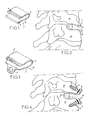
- FIG. 1 is a perspective view of the intervertebral implant in question
- FIG. 2 is a side view thereof after placement thereof
- FIG. 3 is a perspective view of said “fusion” implant
- FIG. 4 is a side view of this “fusion” implant after placement.
- FIGS. 1 and 2 represent an intervertebral implant 1 for the treatment of cervical vertebrae 10 by anterior approach route.
- the implant 1 is realised by folding a given piece of material and exhibits, seen laterally, i.e. in the sagittal plane after implantation, a curved shape delineating two lateral bearing walls 2 and one intermediate wall 3 .
- Said piece of material is a sheet flank made of titanium, aluminium and of vanadium alloy known as “TA6V”.
- the lateral walls 2 show, seen laterally, domed shapes on the greatest portion of their length, the convexities thereof being turned towards the exterior of the implant 1 . At their free end zones, these lateral bearing walls 2 are rectilinear in shape and comprise each a series of ribs 4 .
- the length of the “lower” wall 2 i.e. abutting the lower vertebra during implantation, is greater than that of the other wall 2 .
- the intermediate wall 3 has a curved shape whereof the convexity is turned towards the exterior of the implant. As appears clearly, it does not form any marked angles with the lateral bearing walls 2 , these lateral bearing walls 2 and this intermediate wall 3 having thus, seen laterally, partially oval “water drop”-like shape.
- the intermediate wall 3 is moreover deformable elastically between a neutral form, wherein it maintains normally the walls 2 at a distance from one another which is slightly greater than the height of the intervertebral space to be restored, and a constrained shape, wherein said wall 3 enables to bring the free ends of both walls 2 together. This bringing together is such that it enables to reduce the height of the implant 1 so that such height is smaller than the height of the intervertebral space to be restored.
- the ribs 4 are parallel to one another and protrude from the free end zone of each wall 2 , towards the exterior of the implant 1 . Each of them is delineated by an anterior face perpendicular to the longitudinal direction of the implant 1 and by a tilted posterior face, forming an angle of approximately 500 with the anterior face. These ribs 4 thus exhibit relatively sharp free ridges.
- the implant 1 represented for exemplification purposes exhibits the following dimensions:
- the walls 2 are brought towards one another by deformation of the wall 3 , to enable insertion of the implant 1 between the vertebral plates of the two vertebrae 10 to be treated, then, once said insertion is completed, the walls 2 are released, which presses said walls against these vertebral plates.
- the ribs 4 are inserted in the vertebral plates and enable non rigid assembly of the implant 1 to these vertebrae or tissues, i.e. allowing slight deformation of the implant with respect to the vertebrae as the vertebrae are moving, while opposing any expulsion of the implant.
- the domed shape of the walls 2 enables these walls to match precisely the shape exhibited by the respective faces of these vertebral plates, and ensures certain retention of the implant between the vertebrae 10 .
- the elastic stress remaining in the wall 3 enables to maintain the ribs 4 inserted in the vertebrae 10 .
- the “fusion” implant 11 shown on FIGS. 3 and 4 have a structure similar to that of the implant 1 described above, except that the walls 2 comprise two tabs 5 , interconnected therewith and extend their free ends.
- Each of these tabs 5 is attached to the end of the wall 2 which supports the latter by two curved lateral connection zones, which enable to ensure perfectly solid link of this tab 5 and of the wall 2 , and is drilled with a hole accommodating an anchoring screw 6 .
- This screw 6 is intended to be inserted in the body of the corresponding vertebra 10 , as shown on FIG. 4 .
- Each tab 5 forms an angle of the order of 120.degree. with the general antero-posterior direction of the wall 2 to which said tab is attached, and exhibits a thickness greater than that of the remainder of the implant 1 . This thickness is approximately 1.5 mm in the example represented.
- the “fusion” implant 11 is used to realise a fusion between the two vertebrae 10 to be treated.
- the invention brings a decisive improvement to the anterior technique, by providing an intervertebral implant enabling perfect restoration of the intervertebral space, without opposing the movements of the vertebrae, without inducing any risks of insertion in the vertebral plates nor of risk of fusion by growing bony cells, while being easy to be implanted and whereof the durability is not questionable.
Abstract
Description
-
- said lateral bearing walls show, seen laterally, curved shapes with their convexity turned to the outside of the implant;
- said intermediate wall shows a curved shape, with its convexity turned to the outside of the implant, and is such that it does not form any marked angles with said lateral bearing walls, these lateral bearing walls and this intermediate wall having thus, seen laterally, partial oval “water drop”-like shape; and
- the means for fastening the implant to the vertebrae are designed to enable non rigid assembly of this implant to these vertebrae, i.e. authorising slight deformation of the implant with respect to the vertebrae as the latter are moving.
-
- maximum dimension of the implant in the sagittal plane: approximately 17 mm;
- difference in length of the walls 2: approximately 1 mm;
- dimension of the implant in the front plane: approximately 18 mm;
- thickness of said flank at the
walls 2 and of the wall 3: approximately 1 mm; - maximum thickness of the implant 1, at the exterior domed faces of the lateral walls 2: approximately 7 mm;
- curvature radius of the upper half of the intermediate wall 3: approximately 2.7 mm;
- curvature radius of the lower half of the intermediate wall 3: approximately 3.3 mm;
- curvature radius of the domed zone of the upper lateral wall 2: 10 mm;
- curvature radius of the domed zone of the lower lateral wall 2: approximately 25 mm.
Claims (19)
Priority Applications (1)
| Application Number | Priority Date | Filing Date | Title |
|---|---|---|---|
| US15/042,441 US9610170B2 (en) | 2002-03-15 | 2016-02-12 | Dynamic intervertebral implant |
Applications Claiming Priority (7)
| Application Number | Priority Date | Filing Date | Title |
|---|---|---|---|
| FR0203252A FR2837094B1 (en) | 2002-03-15 | 2002-03-15 | INTERVERTEBRAL IMPLANT |
| FR02/03252 | 2002-03-15 | ||
| FR0203252 | 2002-03-15 | ||
| PCT/FR2003/000799 WO2003077806A1 (en) | 2002-03-15 | 2003-03-13 | Dynamic intervertebral implant |
| US10/506,219 US7867276B2 (en) | 2002-03-15 | 2003-03-13 | Dynamic intervertebral implant |
| US12/986,714 US9259325B2 (en) | 2002-03-15 | 2011-01-07 | Dynamic intervertebral implant |
| US15/042,441 US9610170B2 (en) | 2002-03-15 | 2016-02-12 | Dynamic intervertebral implant |
Related Parent Applications (1)
| Application Number | Title | Priority Date | Filing Date |
|---|---|---|---|
| US12/986,714 Continuation US9259325B2 (en) | 2002-03-15 | 2011-01-07 | Dynamic intervertebral implant |
Publications (2)
| Publication Number | Publication Date |
|---|---|
| US20160166398A1 US20160166398A1 (en) | 2016-06-16 |
| US9610170B2 true US9610170B2 (en) | 2017-04-04 |
Family
ID=27772167
Family Applications (4)
| Application Number | Title | Priority Date | Filing Date |
|---|---|---|---|
| US10/506,219 Active 2025-07-29 US7867276B2 (en) | 2002-03-15 | 2003-03-13 | Dynamic intervertebral implant |
| US12/986,714 Expired - Fee Related US9259325B2 (en) | 2002-03-15 | 2011-01-07 | Dynamic intervertebral implant |
| US12/986,722 Expired - Fee Related US8337555B2 (en) | 2002-03-15 | 2011-01-07 | Dynamic intervertebral implant |
| US15/042,441 Expired - Fee Related US9610170B2 (en) | 2002-03-15 | 2016-02-12 | Dynamic intervertebral implant |
Family Applications Before (3)
| Application Number | Title | Priority Date | Filing Date |
|---|---|---|---|
| US10/506,219 Active 2025-07-29 US7867276B2 (en) | 2002-03-15 | 2003-03-13 | Dynamic intervertebral implant |
| US12/986,714 Expired - Fee Related US9259325B2 (en) | 2002-03-15 | 2011-01-07 | Dynamic intervertebral implant |
| US12/986,722 Expired - Fee Related US8337555B2 (en) | 2002-03-15 | 2011-01-07 | Dynamic intervertebral implant |
Country Status (10)
| Country | Link |
|---|---|
| US (4) | US7867276B2 (en) |
| EP (1) | EP1485045B1 (en) |
| JP (2) | JP4481658B2 (en) |
| KR (1) | KR101033969B1 (en) |
| AU (1) | AU2003227829A1 (en) |
| CA (1) | CA2478842C (en) |
| DE (1) | DE20321907U1 (en) |
| ES (1) | ES2548563T3 (en) |
| FR (1) | FR2837094B1 (en) |
| WO (1) | WO2003077806A1 (en) |
Cited By (1)
| Publication number | Priority date | Publication date | Assignee | Title |
|---|---|---|---|---|
| US10925749B2 (en) | 2013-03-15 | 2021-02-23 | Revivo Medical, Llc | Intervertebral cage and method of treating vertebrae with an intervertebral cage |
Families Citing this family (97)
| Publication number | Priority date | Publication date | Assignee | Title |
|---|---|---|---|---|
| FR2812185B1 (en) | 2000-07-25 | 2003-02-28 | Spine Next Sa | SEMI-RIGID CONNECTION PIECE FOR RACHIS STABILIZATION |
| FR2812186B1 (en) * | 2000-07-25 | 2003-02-28 | Spine Next Sa | FLEXIBLE CONNECTION PIECE FOR SPINAL STABILIZATION |
| US6579319B2 (en) | 2000-11-29 | 2003-06-17 | Medicinelodge, Inc. | Facet joint replacement |
| US20050080486A1 (en) | 2000-11-29 | 2005-04-14 | Fallin T. Wade | Facet joint replacement |
| US6419703B1 (en) | 2001-03-01 | 2002-07-16 | T. Wade Fallin | Prosthesis for the replacement of a posterior element of a vertebra |
| US7090698B2 (en) | 2001-03-02 | 2006-08-15 | Facet Solutions | Method and apparatus for spine joint replacement |
| FR2837094B1 (en) * | 2002-03-15 | 2004-11-26 | Fixano | INTERVERTEBRAL IMPLANT |
| US7291171B2 (en) * | 2002-05-10 | 2007-11-06 | Ferree Bret A | Artificial disc replacement (ADR) using elastic tether member |
| WO2004089240A2 (en) | 2003-04-04 | 2004-10-21 | Theken Disc, Llc | Artificial disc prosthesis |
| FR2860428B1 (en) * | 2003-10-02 | 2006-05-12 | Fixano | INTERVERTEBRAL IMPLANT |
| US7588590B2 (en) | 2003-12-10 | 2009-09-15 | Facet Solutions, Inc | Spinal facet implant with spherical implant apposition surface and bone bed and methods of use |
| US8900273B2 (en) | 2005-02-22 | 2014-12-02 | Gmedelaware 2 Llc | Taper-locking fixation system |
| US8562649B2 (en) | 2004-02-17 | 2013-10-22 | Gmedelaware 2 Llc | System and method for multiple level facet joint arthroplasty and fusion |
| US8333789B2 (en) | 2007-01-10 | 2012-12-18 | Gmedelaware 2 Llc | Facet joint replacement |
| US7993373B2 (en) | 2005-02-22 | 2011-08-09 | Hoy Robert W | Polyaxial orthopedic fastening apparatus |
| US20080269900A1 (en) * | 2004-05-20 | 2008-10-30 | Christopher Reah | Surgical Implants |
| US8764801B2 (en) | 2005-03-28 | 2014-07-01 | Gmedelaware 2 Llc | Facet joint implant crosslinking apparatus and method |
| US7588578B2 (en) | 2004-06-02 | 2009-09-15 | Facet Solutions, Inc | Surgical measurement systems and methods |
| US7758581B2 (en) | 2005-03-28 | 2010-07-20 | Facet Solutions, Inc. | Polyaxial reaming apparatus and method |
| US7854752B2 (en) | 2004-08-09 | 2010-12-21 | Theken Spine, Llc | System and method for dynamic skeletal stabilization |
| CA2574277A1 (en) * | 2004-08-09 | 2006-02-23 | Innovative Spinal Technologies, Inc. | System and method for dynamic skeletal stabilization |
| US7763074B2 (en) | 2004-10-20 | 2010-07-27 | The Board Of Trustees Of The Leland Stanford Junior University | Systems and methods for posterior dynamic stabilization of the spine |
| US8012207B2 (en) | 2004-10-20 | 2011-09-06 | Vertiflex, Inc. | Systems and methods for posterior dynamic stabilization of the spine |
| US9161783B2 (en) | 2004-10-20 | 2015-10-20 | Vertiflex, Inc. | Interspinous spacer |
| US8123782B2 (en) | 2004-10-20 | 2012-02-28 | Vertiflex, Inc. | Interspinous spacer |
| US8152837B2 (en) | 2004-10-20 | 2012-04-10 | The Board Of Trustees Of The Leland Stanford Junior University | Systems and methods for posterior dynamic stabilization of the spine |
| US8277488B2 (en) | 2004-10-20 | 2012-10-02 | Vertiflex, Inc. | Interspinous spacer |
| US8128662B2 (en) | 2004-10-20 | 2012-03-06 | Vertiflex, Inc. | Minimally invasive tooling for delivery of interspinous spacer |
| US8425559B2 (en) | 2004-10-20 | 2013-04-23 | Vertiflex, Inc. | Systems and methods for posterior dynamic stabilization of the spine |
| US9023084B2 (en) | 2004-10-20 | 2015-05-05 | The Board Of Trustees Of The Leland Stanford Junior University | Systems and methods for stabilizing the motion or adjusting the position of the spine |
| US8167944B2 (en) | 2004-10-20 | 2012-05-01 | The Board Of Trustees Of The Leland Stanford Junior University | Systems and methods for posterior dynamic stabilization of the spine |
| WO2009009049A2 (en) | 2004-10-20 | 2009-01-15 | Vertiflex, Inc. | Interspinous spacer |
| US8409282B2 (en) | 2004-10-20 | 2013-04-02 | Vertiflex, Inc. | Systems and methods for posterior dynamic stabilization of the spine |
| US8945183B2 (en) | 2004-10-20 | 2015-02-03 | Vertiflex, Inc. | Interspinous process spacer instrument system with deployment indicator |
| US8123807B2 (en) | 2004-10-20 | 2012-02-28 | Vertiflex, Inc. | Systems and methods for posterior dynamic stabilization of the spine |
| US8613747B2 (en) | 2004-10-20 | 2013-12-24 | Vertiflex, Inc. | Spacer insertion instrument |
| US9119680B2 (en) | 2004-10-20 | 2015-09-01 | Vertiflex, Inc. | Interspinous spacer |
| US8317864B2 (en) | 2004-10-20 | 2012-11-27 | The Board Of Trustees Of The Leland Stanford Junior University | Systems and methods for posterior dynamic stabilization of the spine |
| EP2219538B1 (en) | 2004-12-06 | 2022-07-06 | Vertiflex, Inc. | Spacer insertion instrument |
| JP4601051B2 (en) * | 2004-12-20 | 2010-12-22 | 株式会社ユニバーサルエンターテインメント | Gaming chips |
| US7361196B2 (en) | 2005-02-22 | 2008-04-22 | Stryker Spine | Apparatus and method for dynamic vertebral stabilization |
| US7722647B1 (en) | 2005-03-14 | 2010-05-25 | Facet Solutions, Inc. | Apparatus and method for posterior vertebral stabilization |
| US8267970B2 (en) * | 2005-10-25 | 2012-09-18 | Depuy Spine, Inc. | Laminar hook spring |
| US8109973B2 (en) | 2005-10-31 | 2012-02-07 | Stryker Spine | Method for dynamic vertebral stabilization |
| US7578849B2 (en) * | 2006-01-27 | 2009-08-25 | Warsaw Orthopedic, Inc. | Intervertebral implants and methods of use |
| US7682376B2 (en) | 2006-01-27 | 2010-03-23 | Warsaw Orthopedic, Inc. | Interspinous devices and methods of use |
| US7815663B2 (en) | 2006-01-27 | 2010-10-19 | Warsaw Orthopedic, Inc. | Vertebral rods and methods of use |
| US20070225806A1 (en) * | 2006-03-24 | 2007-09-27 | Sdgi Holdings, Inc. | Arthroplasty device |
| US8282641B2 (en) | 2006-03-28 | 2012-10-09 | Depuy Spine, Inc. | Methods and instrumentation for disc replacement |
| US8137404B2 (en) * | 2006-03-28 | 2012-03-20 | Depuy Spine, Inc. | Artificial disc replacement using posterior approach |
| US20070233244A1 (en) * | 2006-03-28 | 2007-10-04 | Depuy Spine, Inc. | Artificial Disc Replacement Using Posterior Approach |
| US8025681B2 (en) | 2006-03-29 | 2011-09-27 | Theken Spine, Llc | Dynamic motion spinal stabilization system |
| KR100774245B1 (en) * | 2006-03-29 | 2007-11-07 | 주식회사 경원메디칼 | A clip for suturing a dura mater |
| EP2012686B1 (en) * | 2006-04-18 | 2013-10-02 | Joseph Nicholas Logan | Spinal rod system |
| FR2902639B1 (en) * | 2006-06-26 | 2008-08-22 | Arca Medica Gmbh | IMPLANT INTENDED FOR THE STABILIZATION OF THE SACRED LOMBO REGION |
| US8845726B2 (en) | 2006-10-18 | 2014-09-30 | Vertiflex, Inc. | Dilator |
| AR064013A1 (en) * | 2006-11-30 | 2009-03-04 | Paradigm Spine Llc | VERTEBRAL, INTERLAMINAR, INTERESPINOUS STABILIZATION SYSTEM |
| US8715352B2 (en) * | 2006-12-14 | 2014-05-06 | Depuy Spine, Inc. | Buckling disc replacement |
| US8034081B2 (en) | 2007-02-06 | 2011-10-11 | CollabComl, LLC | Interspinous dynamic stabilization implant and method of implanting |
| FR2913328A1 (en) * | 2007-03-09 | 2008-09-12 | Henry Graf | Intervertebral dynamic stabilization assembly for arthrodesis of adjacent vertebrae, has elastic units interacting until equilibrium point is found, where point is controlled by external forces e.g. patient weight of and muscle contraction |
| WO2008123879A1 (en) * | 2007-04-05 | 2008-10-16 | Warsaw Orthopedic, Inc. | Arthroplasty device |
| EP2155121B1 (en) | 2007-04-16 | 2015-06-17 | Vertiflex, Inc. | Interspinous spacer |
| US9173686B2 (en) * | 2007-05-09 | 2015-11-03 | Ebi, Llc | Interspinous implant |
| US9381047B2 (en) | 2007-05-09 | 2016-07-05 | Ebi, Llc | Interspinous implant |
| US8282681B2 (en) | 2007-08-13 | 2012-10-09 | Nuvasive, Inc. | Bioresorbable spinal implant and related methods |
| EP2197374B1 (en) * | 2007-09-14 | 2018-10-31 | Synthes GmbH | Interspinous spacer |
| US20090076608A1 (en) * | 2007-09-17 | 2009-03-19 | Vermillion Technologies, Llc | Intervertebral disc replacement prosthesis |
| EP2244670B1 (en) | 2008-01-15 | 2017-09-13 | Vertiflex, Inc. | Interspinous spacer |
| US8167949B2 (en) * | 2008-01-25 | 2012-05-01 | Aesculap Implant Systems, Llc | Hydrostatic interbody |
| US8377135B1 (en) | 2008-03-31 | 2013-02-19 | Nuvasive, Inc. | Textile-based surgical implant and related methods |
| KR101547212B1 (en) * | 2008-04-22 | 2015-08-25 | 키네틱 스파인 테크놀로지스 인크. | Artificial intervertebral spacer |
| US8182539B2 (en) * | 2008-10-23 | 2012-05-22 | Aesculap Implant Systems, Llc | Dynamic interbody with motion control mechanisms |
| DE102009021134A1 (en) * | 2009-05-13 | 2010-11-18 | Aesculap Ag | Facet joint implant |
| JP2011152156A (en) * | 2009-05-26 | 2011-08-11 | Minatogawa Kinzoku Test Piece Mfg Co Ltd | Intervertebral implant |
| US8740948B2 (en) | 2009-12-15 | 2014-06-03 | Vertiflex, Inc. | Spinal spacer for cervical and other vertebra, and associated systems and methods |
| US8388656B2 (en) * | 2010-02-04 | 2013-03-05 | Ebi, Llc | Interspinous spacer with deployable members and related method |
| EP2538889A1 (en) * | 2010-02-22 | 2013-01-02 | Synthes GmbH | Total disc replacement with w-shaped spring elements |
| KR101052833B1 (en) * | 2010-10-28 | 2011-07-29 | 박경우 | A intervertebral cage having flexibility |
| FR2973221B1 (en) * | 2011-04-04 | 2014-02-28 | Groupe Lepine | INTERVERTEBRAL IMPLANT, IN PARTICULAR TO BE IMPLANTED BETWEEN TWO CERVICAL VERTEBRATES |
| WO2013025702A1 (en) | 2011-08-16 | 2013-02-21 | Osteospring Medical, Inc. | Wedge shaped fracture fixation devices and methods for using the same |
| US9668783B2 (en) * | 2011-09-06 | 2017-06-06 | Atul Goel | Devices and method for treatment of spondylotic disease |
| TWI445523B (en) * | 2011-12-09 | 2014-07-21 | Metal Ind Res & Dev Ct | Cage-shaped spinal frame |
| US8696752B2 (en) * | 2011-12-30 | 2014-04-15 | Metal Industries Research & Development Centre | Interbody cage for spine fusion |
| EP2922504A1 (en) * | 2012-11-21 | 2015-09-30 | K2M, Inc. | Flanged endplate for an intervertebral disc prosthesis and intervertebral disc prosthesis incorporating same |
| US9149366B2 (en) * | 2013-03-14 | 2015-10-06 | Warsaw Orthopedic, Inc. | Adaptable interbody implant and methods of use |
| US9510872B2 (en) | 2013-03-15 | 2016-12-06 | Jcbd, Llc | Spinal stabilization system |
| US10154861B2 (en) | 2013-03-15 | 2018-12-18 | Jcbd, Llc | Spinal stabilization system |
| WO2014145766A1 (en) * | 2013-03-15 | 2014-09-18 | Paradigm Spine, Llc | Modular, customizable spine stabilization system |
| US9675303B2 (en) | 2013-03-15 | 2017-06-13 | Vertiflex, Inc. | Visualization systems, instruments and methods of using the same in spinal decompression procedures |
| US9198774B2 (en) * | 2013-11-21 | 2015-12-01 | Perumala Corporation | Intervertebral disk cage and stabilizer |
| AU2015256024B2 (en) | 2014-05-07 | 2020-03-05 | Vertiflex, Inc. | Spinal nerve decompression systems, dilation systems, and methods of using the same |
| GB201416867D0 (en) | 2014-09-24 | 2014-11-05 | Fitzbionics Ltd | A prosthetic intervertebral disc joint assembly |
| FR3029770B1 (en) * | 2014-12-12 | 2019-11-08 | Hassan Razian | INTERVERTEBRAL CAGE |
| CN104546229B (en) * | 2015-01-19 | 2017-01-04 | 南京航空航天大学 | A kind of cervical artificial disc of the corner cut Ω type structure with superelevation mobility |
| CN104546230B (en) * | 2015-01-19 | 2017-02-01 | 南京航空航天大学 | Artificial cervical intervertebral disc based on bending section with reversed U-shaped structure having like-trapezoidal section |
| US10537434B2 (en) * | 2016-08-08 | 2020-01-21 | Wu Jau Ching | Intervertebral implant |
| CA3124694A1 (en) * | 2019-04-29 | 2020-11-05 | Aurora Spine, Inc. | Spinal implant for motion preservation or fusion |
Citations (6)
| Publication number | Priority date | Publication date | Assignee | Title |
|---|---|---|---|---|
| US5645599A (en) | 1994-07-26 | 1997-07-08 | Fixano | Interspinal vertebral implant |
| US5749916A (en) | 1997-01-21 | 1998-05-12 | Spinal Innovations | Fusion implant |
| US6610093B1 (en) | 2000-07-28 | 2003-08-26 | Perumala Corporation | Method and apparatus for stabilizing adjacent vertebrae |
| US20080262617A1 (en) | 2007-04-19 | 2008-10-23 | Zimmer Gmbh | Interspinous spacer |
| US20090118833A1 (en) | 2007-11-05 | 2009-05-07 | Zimmer Spine, Inc. | In-situ curable interspinous process spacer |
| US7867276B2 (en) * | 2002-03-15 | 2011-01-11 | Paradigm Spine, Llc | Dynamic intervertebral implant |
Family Cites Families (23)
| Publication number | Priority date | Publication date | Assignee | Title |
|---|---|---|---|---|
| CA1146301A (en) * | 1980-06-13 | 1983-05-17 | J. David Kuntz | Intervertebral disc prosthesis |
| US5306307A (en) * | 1991-07-22 | 1994-04-26 | Calcitek, Inc. | Spinal disk implant |
| JPH05317407A (en) | 1992-05-27 | 1993-12-03 | Nippon Electric Glass Co Ltd | Artificial intervertebral plate |
| US5415661A (en) * | 1993-03-24 | 1995-05-16 | University Of Miami | Implantable spinal assist device |
| DE4315757C1 (en) * | 1993-05-11 | 1994-11-10 | Plus Endoprothetik Ag | Vertebral implant |
| US5674296A (en) * | 1994-11-14 | 1997-10-07 | Spinal Dynamics Corporation | Human spinal disc prosthesis |
| FR2728159B1 (en) * | 1994-12-16 | 1997-06-27 | Tornier Sa | ELASTIC DISC PROSTHESIS |
| FR2733413B1 (en) * | 1995-04-27 | 1997-10-17 | Jbs Sa | CERVICAL CAGE DEVICE FOR PERFORMING INTERSOMATIC ARTHRODESIS |
| AU705598B2 (en) * | 1995-12-08 | 1999-05-27 | Robert S. Bray Jr. | Anterior stabilization device |
| FR2747034B1 (en) * | 1996-04-03 | 1998-06-19 | Scient X | INTERSOMATIC CONTAINMENT AND MERGER SYSTEM |
| FR2753368B1 (en) * | 1996-09-13 | 1999-01-08 | Chauvin Jean Luc | EXPANSIONAL OSTEOSYNTHESIS CAGE |
| US5836948A (en) * | 1997-01-02 | 1998-11-17 | Saint Francis Medical Technologies, Llc | Spine distraction implant and method |
| GB9713330D0 (en) * | 1997-06-25 | 1997-08-27 | Bridport Gundry Plc | Surgical implant |
| FR2767675B1 (en) * | 1997-08-26 | 1999-12-03 | Materiel Orthopedique En Abreg | INTERSOMATIC IMPLANT AND ANCILLARY OF PREPARATION SUITABLE FOR ALLOWING ITS POSITION |
| AU748746B2 (en) | 1998-07-22 | 2002-06-13 | Spinal Dynamics Corporation | Threaded cylindrical multidiscoid single or multiple array disc prosthesis |
| US6325805B1 (en) * | 1999-04-23 | 2001-12-04 | Sdgi Holdings, Inc. | Shape memory alloy staple |
| FR2805457B1 (en) * | 2000-02-24 | 2002-10-11 | Stryker Spine Sa | INTERVERTEBRAL IMPLANT WITH BODY AND SUPPORT SIDE |
| US20020130112A1 (en) * | 2000-06-05 | 2002-09-19 | Mark Manasas | Orthopedic implant and method of making metal articles |
| FR2812806A1 (en) * | 2000-08-08 | 2002-02-15 | Patrick Philibert Henry | Semi-rigid intersomatic implant for fusing vertebrae has horizontal U-shaped body with holed for bone graft |
| US6443989B1 (en) * | 2000-12-04 | 2002-09-03 | Roger P. Jackson | Posterior expandable fusion cage |
| US6743257B2 (en) * | 2000-12-19 | 2004-06-01 | Cortek, Inc. | Dynamic implanted intervertebral spacer |
| US20020120340A1 (en) * | 2001-02-23 | 2002-08-29 | Metzger Robert G. | Knee joint prosthesis |
| JP3629557B2 (en) * | 2001-04-28 | 2005-03-16 | 李 春澤 | Spinal fusion transfer |
-
2002
- 2002-03-15 FR FR0203252A patent/FR2837094B1/en not_active Expired - Fee Related
-
2003
- 2003-03-13 EP EP03725283.0A patent/EP1485045B1/en not_active Expired - Lifetime
- 2003-03-13 ES ES03725283.0T patent/ES2548563T3/en not_active Expired - Lifetime
- 2003-03-13 DE DE20321907U patent/DE20321907U1/en not_active Expired - Lifetime
- 2003-03-13 CA CA2478842A patent/CA2478842C/en not_active Expired - Fee Related
- 2003-03-13 US US10/506,219 patent/US7867276B2/en active Active
- 2003-03-13 KR KR1020047014416A patent/KR101033969B1/en active IP Right Grant
- 2003-03-13 JP JP2003575862A patent/JP4481658B2/en not_active Expired - Lifetime
- 2003-03-13 WO PCT/FR2003/000799 patent/WO2003077806A1/en active Application Filing
- 2003-03-13 AU AU2003227829A patent/AU2003227829A1/en not_active Abandoned
-
2009
- 2009-11-02 JP JP2009252098A patent/JP4971408B2/en not_active Expired - Lifetime
-
2011
- 2011-01-07 US US12/986,714 patent/US9259325B2/en not_active Expired - Fee Related
- 2011-01-07 US US12/986,722 patent/US8337555B2/en not_active Expired - Fee Related
-
2016
- 2016-02-12 US US15/042,441 patent/US9610170B2/en not_active Expired - Fee Related
Patent Citations (7)
| Publication number | Priority date | Publication date | Assignee | Title |
|---|---|---|---|---|
| US5645599A (en) | 1994-07-26 | 1997-07-08 | Fixano | Interspinal vertebral implant |
| US5749916A (en) | 1997-01-21 | 1998-05-12 | Spinal Innovations | Fusion implant |
| US6610093B1 (en) | 2000-07-28 | 2003-08-26 | Perumala Corporation | Method and apparatus for stabilizing adjacent vertebrae |
| US7867276B2 (en) * | 2002-03-15 | 2011-01-11 | Paradigm Spine, Llc | Dynamic intervertebral implant |
| US9259325B2 (en) * | 2002-03-15 | 2016-02-16 | Paradigm Spine, Llc | Dynamic intervertebral implant |
| US20080262617A1 (en) | 2007-04-19 | 2008-10-23 | Zimmer Gmbh | Interspinous spacer |
| US20090118833A1 (en) | 2007-11-05 | 2009-05-07 | Zimmer Spine, Inc. | In-situ curable interspinous process spacer |
Non-Patent Citations (1)
| Title |
|---|
| European Office Action dated Apr. 2, 2014 issued in European Patent Application No. 03 725 283. |
Cited By (1)
| Publication number | Priority date | Publication date | Assignee | Title |
|---|---|---|---|---|
| US10925749B2 (en) | 2013-03-15 | 2021-02-23 | Revivo Medical, Llc | Intervertebral cage and method of treating vertebrae with an intervertebral cage |
Also Published As
| Publication number | Publication date |
|---|---|
| US7867276B2 (en) | 2011-01-11 |
| DE20321907U1 (en) | 2012-10-29 |
| KR101033969B1 (en) | 2011-05-11 |
| JP2010042287A (en) | 2010-02-25 |
| US9259325B2 (en) | 2016-02-16 |
| EP1485045A1 (en) | 2004-12-15 |
| CA2478842C (en) | 2011-09-13 |
| JP4481658B2 (en) | 2010-06-16 |
| FR2837094B1 (en) | 2004-11-26 |
| US20110106256A1 (en) | 2011-05-05 |
| ES2548563T3 (en) | 2015-10-19 |
| US8337555B2 (en) | 2012-12-25 |
| US20050125063A1 (en) | 2005-06-09 |
| US20110106257A1 (en) | 2011-05-05 |
| US20160166398A1 (en) | 2016-06-16 |
| JP4971408B2 (en) | 2012-07-11 |
| AU2003227829A1 (en) | 2003-09-29 |
| JP2005520598A (en) | 2005-07-14 |
| WO2003077806A1 (en) | 2003-09-25 |
| EP1485045B1 (en) | 2015-07-01 |
| CA2478842A1 (en) | 2003-09-25 |
| KR20040091735A (en) | 2004-10-28 |
| FR2837094A1 (en) | 2003-09-19 |
Similar Documents
| Publication | Publication Date | Title |
|---|---|---|
| US9610170B2 (en) | Dynamic intervertebral implant | |
| US10322008B2 (en) | Intervertebral spinal implant | |
| US10045859B2 (en) | Cervical and lumbar spinal interbody devices | |
| US6520993B2 (en) | Spinal implant | |
| EP0599419A2 (en) | Disk-shaped implant for reinforcing adjacent vertebrae | |
| US20180036136A1 (en) | Intervertebral fusion implant | |
| US5904719A (en) | Interbody fusion device having partial circular section cross-sectional segments | |
| US20040230307A1 (en) | Device for fusing two bone segments | |
| JPH10234755A (en) | Artificial prosthetic article for fixing intervertebral joint | |
| US20080208342A1 (en) | Spinal implant | |
| AU2004277356A1 (en) | Intervertebral implant | |
| US5108440A (en) | Shoulder implant | |
| US20110230913A1 (en) | Facet joint prosthesis | |
| US11083590B2 (en) | Intersomatic prosthesis with lateral introduction | |
| US20020103540A1 (en) | Spinal fusion implant | |
| EP3727174B1 (en) | Improved partial endoprosthesis device for a vertebral joint | |
| EP1596772B1 (en) | Device for fusing two bone segments | |
| KR200216074Y1 (en) | The adjustable body replacement fusion cage | |
| US20080234825A1 (en) | Modular Lumbar Interbody Fixation Systems and Methods |
Legal Events
| Date | Code | Title | Description |
|---|---|---|---|
| AS | Assignment |
Owner name: HAYFIN SERVICES LLP, UNITED KINGDOM Free format text: SECURITY INTEREST;ASSIGNOR:PARADIGM SPINE, LLC;REEL/FRAME:039842/0877 Effective date: 20160826 |
|
| STCF | Information on status: patent grant |
Free format text: PATENTED CASE |
|
| AS | Assignment |
Owner name: JPMORGAN CHASE BANK, N.A., AS ADMINISTRATIVE AGENT, ILLINOIS Free format text: SECURITY INTEREST;ASSIGNORS:PARADIGM SPINE, LLC;FOURTH DIMENSION SPINE, LLC;REEL/FRAME:048538/0026 Effective date: 20190308 Owner name: JPMORGAN CHASE BANK, N.A., AS ADMINISTRATIVE AGENT Free format text: SECURITY INTEREST;ASSIGNORS:PARADIGM SPINE, LLC;FOURTH DIMENSION SPINE, LLC;REEL/FRAME:048538/0026 Effective date: 20190308 Owner name: ARES CAPITAL CORPORATION, AS ADMINISTRATIVE AGENT, Free format text: SECURITY INTEREST;ASSIGNORS:RTI SURGICAL, INC.;PIONEER SURGICAL TECHNOLOGY, INC.;TUTOGEN MEDICAL, INC.;AND OTHERS;REEL/FRAME:048543/0505 Effective date: 20190308 Owner name: ARES CAPITAL CORPORATION, AS ADMINISTRATIVE AGENT, NEW YORK Free format text: SECURITY INTEREST;ASSIGNORS:RTI SURGICAL, INC.;PIONEER SURGICAL TECHNOLOGY, INC.;TUTOGEN MEDICAL, INC.;AND OTHERS;REEL/FRAME:048543/0505 Effective date: 20190308 |
|
| AS | Assignment |
Owner name: PARADIGM SPINE, LLC, NEW YORK Free format text: RELEASE BY SECURED PARTY;ASSIGNOR:HAYFIN SERVICES LLP, AS ADMINISTRATIVE AGENT;REEL/FRAME:050426/0001 Effective date: 20190308 |
|
| FEPP | Fee payment procedure |
Free format text: ENTITY STATUS SET TO UNDISCOUNTED (ORIGINAL EVENT CODE: BIG.); ENTITY STATUS OF PATENT OWNER: LARGE ENTITY |
|
| AS | Assignment |
Owner name: PARADIGM SPINE, LLC, NEW YORK Free format text: TERMINATION AND RELEASE OF SECURITY INTEREST IN PATENTS;ASSIGNOR:HAYFIN SERVICES LLP;REEL/FRAME:050236/0828 Effective date: 20190308 |
|
| AS | Assignment |
Owner name: PIONEER SURGICAL TECHNOLOGY, INC., FLORIDA Free format text: RELEASE BY SECURED PARTY;ASSIGNOR:ARES CAPITAL CORPORATION, AS AGENT;REEL/FRAME:053257/0652 Effective date: 20200720 Owner name: PARADIGM SPINE, LLC, NEW YORK Free format text: RELEASE BY SECURED PARTY;ASSIGNOR:ARES CAPITAL CORPORATION, AS AGENT;REEL/FRAME:053257/0652 Effective date: 20200720 Owner name: FOURTH DIMENSION SPINE, LLC, NEW YORK Free format text: RELEASE BY SECURED PARTY;ASSIGNOR:ARES CAPITAL CORPORATION, AS AGENT;REEL/FRAME:053257/0652 Effective date: 20200720 Owner name: RTI SURGICAL, INC., FLORIDA Free format text: RELEASE BY SECURED PARTY;ASSIGNOR:ARES CAPITAL CORPORATION, AS AGENT;REEL/FRAME:053257/0652 Effective date: 20200720 Owner name: TUTOGEN MEDICAL, INC., FLORIDA Free format text: RELEASE BY SECURED PARTY;ASSIGNOR:ARES CAPITAL CORPORATION, AS AGENT;REEL/FRAME:053257/0652 Effective date: 20200720 |
|
| AS | Assignment |
Owner name: PARADIGM SPINE, LLC, FLORIDA Free format text: RELEASE BY SECURED PARTY;ASSIGNOR:JPMORGAN CHASE BANK, N.A., AS ADMINISTRATIVE AGENT;REEL/FRAME:053260/0156 Effective date: 20200720 Owner name: FOURTH DIMENSION SPINE, LLC, FLORIDA Free format text: RELEASE BY SECURED PARTY;ASSIGNOR:JPMORGAN CHASE BANK, N.A., AS ADMINISTRATIVE AGENT;REEL/FRAME:053260/0156 Effective date: 20200720 |
|
| FEPP | Fee payment procedure |
Free format text: MAINTENANCE FEE REMINDER MAILED (ORIGINAL EVENT CODE: REM.); ENTITY STATUS OF PATENT OWNER: LARGE ENTITY |
|
| LAPS | Lapse for failure to pay maintenance fees |
Free format text: PATENT EXPIRED FOR FAILURE TO PAY MAINTENANCE FEES (ORIGINAL EVENT CODE: EXP.); ENTITY STATUS OF PATENT OWNER: LARGE ENTITY |
|
| STCH | Information on status: patent discontinuation |
Free format text: PATENT EXPIRED DUE TO NONPAYMENT OF MAINTENANCE FEES UNDER 37 CFR 1.362 |
|
| FP | Lapsed due to failure to pay maintenance fee |
Effective date: 20210404 |