US9634445B1 - Electrical bus bar connector system - Google Patents
Electrical bus bar connector system Download PDFInfo
- Publication number
- US9634445B1 US9634445B1 US15/182,748 US201615182748A US9634445B1 US 9634445 B1 US9634445 B1 US 9634445B1 US 201615182748 A US201615182748 A US 201615182748A US 9634445 B1 US9634445 B1 US 9634445B1
- Authority
- US
- United States
- Prior art keywords
- bus bar
- spring
- distribution center
- spring clip
- bus bars
- Prior art date
- Legal status (The legal status is an assumption and is not a legal conclusion. Google has not performed a legal analysis and makes no representation as to the accuracy of the status listed.)
- Active
Links
- 239000000463 material Substances 0.000 claims description 24
- RYGMFSIKBFXOCR-UHFFFAOYSA-N Copper Chemical compound [Cu] RYGMFSIKBFXOCR-UHFFFAOYSA-N 0.000 claims description 6
- 229910052802 copper Inorganic materials 0.000 claims description 6
- 239000010949 copper Substances 0.000 claims description 6
- 229910000639 Spring steel Inorganic materials 0.000 claims description 5
- 230000013011 mating Effects 0.000 claims description 5
- 238000003780 insertion Methods 0.000 description 6
- 230000037431 insertion Effects 0.000 description 6
- 238000010586 diagram Methods 0.000 description 2
- 229910000881 Cu alloy Inorganic materials 0.000 description 1
- 239000000956 alloy Substances 0.000 description 1
- 238000013459 approach Methods 0.000 description 1
- 230000000712 assembly Effects 0.000 description 1
- 238000000429 assembly Methods 0.000 description 1
- 239000002131 composite material Substances 0.000 description 1
- 239000004020 conductor Substances 0.000 description 1
- 239000003989 dielectric material Substances 0.000 description 1
- 230000000694 effects Effects 0.000 description 1
- 238000004519 manufacturing process Methods 0.000 description 1
- 239000002245 particle Substances 0.000 description 1
- 229920005594 polymer fiber Polymers 0.000 description 1
Images


Classifications
-
- H—ELECTRICITY
- H01—ELECTRIC ELEMENTS
- H01R—ELECTRICALLY-CONDUCTIVE CONNECTIONS; STRUCTURAL ASSOCIATIONS OF A PLURALITY OF MUTUALLY-INSULATED ELECTRICAL CONNECTING ELEMENTS; COUPLING DEVICES; CURRENT COLLECTORS
- H01R25/00—Coupling parts adapted for simultaneous co-operation with two or more identical counterparts, e.g. for distributing energy to two or more circuits
- H01R25/16—Rails or bus-bars provided with a plurality of discrete connecting locations for counterparts
- H01R25/161—Details
- H01R25/162—Electrical connections between or with rails or bus-bars
-
- H—ELECTRICITY
- H01—ELECTRIC ELEMENTS
- H01R—ELECTRICALLY-CONDUCTIVE CONNECTIONS; STRUCTURAL ASSOCIATIONS OF A PLURALITY OF MUTUALLY-INSULATED ELECTRICAL CONNECTING ELEMENTS; COUPLING DEVICES; CURRENT COLLECTORS
- H01R4/00—Electrically-conductive connections between two or more conductive members in direct contact, i.e. touching one another; Means for effecting or maintaining such contact; Electrically-conductive connections having two or more spaced connecting locations for conductors and using contact members penetrating insulation
- H01R4/28—Clamped connections, spring connections
- H01R4/48—Clamped connections, spring connections utilising a spring, clip, or other resilient member
- H01R4/4809—Clamped connections, spring connections utilising a spring, clip, or other resilient member using a leaf spring to bias the conductor toward the busbar
-
- H—ELECTRICITY
- H01—ELECTRIC ELEMENTS
- H01R—ELECTRICALLY-CONDUCTIVE CONNECTIONS; STRUCTURAL ASSOCIATIONS OF A PLURALITY OF MUTUALLY-INSULATED ELECTRICAL CONNECTING ELEMENTS; COUPLING DEVICES; CURRENT COLLECTORS
- H01R9/00—Structural associations of a plurality of mutually-insulated electrical connecting elements, e.g. terminal strips or terminal blocks; Terminals or binding posts mounted upon a base or in a case; Bases therefor
- H01R9/22—Bases, e.g. strip, block, panel
- H01R9/226—Bases, e.g. strip, block, panel comprising a plurality of conductive flat strips providing connection between wires or components
-
- H—ELECTRICITY
- H01—ELECTRIC ELEMENTS
- H01R—ELECTRICALLY-CONDUCTIVE CONNECTIONS; STRUCTURAL ASSOCIATIONS OF A PLURALITY OF MUTUALLY-INSULATED ELECTRICAL CONNECTING ELEMENTS; COUPLING DEVICES; CURRENT COLLECTORS
- H01R31/00—Coupling parts supported only by co-operation with counterpart
- H01R31/08—Short-circuiting members for bridging contacts in a counterpart
- H01R31/085—Short circuiting bus-strips
-
- H—ELECTRICITY
- H01—ELECTRIC ELEMENTS
- H01R—ELECTRICALLY-CONDUCTIVE CONNECTIONS; STRUCTURAL ASSOCIATIONS OF A PLURALITY OF MUTUALLY-INSULATED ELECTRICAL CONNECTING ELEMENTS; COUPLING DEVICES; CURRENT COLLECTORS
- H01R4/00—Electrically-conductive connections between two or more conductive members in direct contact, i.e. touching one another; Means for effecting or maintaining such contact; Electrically-conductive connections having two or more spaced connecting locations for conductors and using contact members penetrating insulation
- H01R4/28—Clamped connections, spring connections
- H01R4/48—Clamped connections, spring connections utilising a spring, clip, or other resilient member
-
- H—ELECTRICITY
- H01—ELECTRIC ELEMENTS
- H01H—ELECTRIC SWITCHES; RELAYS; SELECTORS; EMERGENCY PROTECTIVE DEVICES
- H01H85/00—Protective devices in which the current flows through a part of fusible material and this current is interrupted by displacement of the fusible material when this current becomes excessive
- H01H85/02—Details
- H01H85/20—Bases for supporting the fuse; Separate parts thereof
- H01H2085/2075—Junction box, having holders integrated with several other holders in a particular wiring layout
- H01H2085/208—Junction box, having holders integrated with several other holders in a particular wiring layout specially adapted for vehicles
-
- H—ELECTRICITY
- H01—ELECTRIC ELEMENTS
- H01R—ELECTRICALLY-CONDUCTIVE CONNECTIONS; STRUCTURAL ASSOCIATIONS OF A PLURALITY OF MUTUALLY-INSULATED ELECTRICAL CONNECTING ELEMENTS; COUPLING DEVICES; CURRENT COLLECTORS
- H01R2201/00—Connectors or connections adapted for particular applications
- H01R2201/26—Connectors or connections adapted for particular applications for vehicles
Definitions
- the invention generally relates to electrical connectors and more particularly relates to a system for interconnecting two or more electrical bus bars.
- bus bars to conduct large currents.
- the bus bar may conduct current from a power source, such as a vehicle battery, to various electrical loads or components.
- the bus bars are typically formed from bars of conductive material, e.g. a copper alloy.
- fasteners such as bolts and nuts or rivets.
- Other solutions have used interference fitting of the bus bars, for example a male mating feature on one bus bar and a female mating feature on another.
- Each of these connection bus bar schemes require special tools to fasten the nuts or rivets or precise tolerances of the mating features to ensure a reliable and low resistance connection between the bus bars.
- the bus bar assembly may require very precise placement to align the bus bar assembly with electrical contacts or housings. Therefore, a system for interconnecting two or more bus bars that does not require special tools and/or precise tolerances remains to be desired.
- a bus bar connector system in accordance with one embodiment of this invention, includes a first bus bar, a second bus bar, and a spring clip configured to apply a contact force to the first and second bus bars effective to bring at least a portion the first and second bus bars into intimate contact with one another.
- the first bus bar may be configured to supply current from a power supply and the second bus bar may be configured to supply current to an electrical device.
- the spring clip may comprise two longitudinal spring arms extending from a lateral spring base connecting the spring arms. These spring arms may be angled toward one another. End portions of the spring arms may be angled away from one another and the end portions of the spring arms may be configured to retain the spring clip within a slot defined by a connector housing.
- the first bus bar may define a longitudinal contact bump protruding from a side of the first bus bar facing the second bus bar.
- the electrical conductivity of the material forming the spring clip may be less than the electrical conductivity of the materials forming the first and second bus bars.
- the bus spring clip may be formed from a spring steel material and the first and second bus bars may be formed of copper-based materials. Alternatively, the spring clip may be formed from a dielectric material while the first and second bus bars are formed of copper-based materials.
- the bus bar connector system may be configured for use in a motor vehicle.
- an electrical distribution center in accordance with another embodiment of this invention, includes a housing containing an electrical device, a first bus bar configured to supply current from a power supply, a second bus bar configured to supply current to the electrical device, and a spring clip disposed within a slot defined by the housing and configured to apply a contact force to the first and second bus bars effective to bring at least a portion the first and second bus bars into intimate contact with one another.
- the electrical device may be selected from the group consisting of relays and fuses.
- the spring clip may comprise two longitudinal spring arms extending from a lateral spring base connecting the spring arms and the spring arms may be angled toward one another. End portions of the spring arms may be angled away from one another.
- the first and second bus bars are disposed intermediate the spring arms.
- Side walls forming the slot may define retaining features protruding from the side walls.
- the end portions of the spring arms interface with these retaining features to retain the spring clip within the slot.
- the first bus bar may define a longitudinal contact bump protruding from a side of the first bus bar facing the second bus bar.
- the electrical conductivity of the material forming the spring clip may be less than the electrical conductivity of the materials forming the first and second bus bars.
- the spring clip may be formed from a spring steel material and the first and second bus bars may be formed of copper-based materials.
- the housing may comprise a first member and a second member that, when mated, form the housing.
- the first bus bar may be disposed within the first member prior to mating with the second member and the second bus bar and the spring clip may be disposed within the slot which is defined by the second member.
- FIG. 1 is perspective view of an electrical distribution center in accordance with one embodiment
- FIG. 2 is a cutaway view of a subassembly of a bus bar connector assembly within the electrical distribution center of FIG. 1 in accordance with one embodiment
- FIG. 3 is a diagram of a force/travel curve for the insertion and removal of a first bus bar from the spring clip as in FIG. 2 in accordance with one embodiment
- FIG. 4 is a cutaway view of the bus bar connector assembly within the electrical distribution center of FIG. 1 in accordance with one embodiment
- FIG. 5A is an isolated view of the bus bar connector assembly of FIG. 4 in accordance with one embodiment
- FIG. 5B is another isolated view of the bus bar connector assembly of FIG. 4 viewed from the side opposite that shown in FIG. 5A in accordance with one embodiment
- FIG. 6 is a diagram of a force/travel curve for the insertion and removal of a second bus bar from the spring clip as in FIG. 4 in accordance with one embodiment.
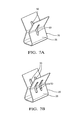
- FIGS. 7A and 7B are perspective views of alternative spring clip designs in accordance with one embodiment.
- a bus bar connector system including a spring clip that provides a high current interface between bus bars in a modular solution.
- the spring clip does this because of its base material properties which produce high normal force between bus bars. It is also a relatively simple geometry compared to a four sided box with an internal spring.
- the spring clip is based on very simple engineering principles. Two “spring arms” of the spring clip are angled towards each other and are designed to provide equal opposing normal forces to the bus bars through two point contacts of the spring arms. The geometry of the spring clip inhibits the occurrence of an over stressed condition.
- the bus bars are stacked in the spring clip with the spring contact at the midpoint.
- a contacting surface of one of the bus bars may be a smooth and flat surface while a contacting surface of another of the bus bar has raised ridges in order to create point contacts between the bus bars.
- This bus bar connector system is suitable for use in an electrical distribution center such as is used in a motor vehicle.
- FIG. 1 illustrates a non-limiting example of an electrical distribution center used in a motor vehicle (not shown), hereinafter referred to as a distribution center 10 .
- the distribution center 10 is used to provide electrical power from a main power source (not shown), such as the vehicle battery, to various components, such as motors, lights, controllers, etc. (not shown) throughout the vehicle through wire cables formed into wiring harnesses (not shown) connected between the components and the distribution center 10 .
- the distribution center 10 includes electrical devices such as fuses 12 configured to protect the cables in the wiring harness from overcurrent conditions and relays 14 configured to switch electrical power to selected circuits in the wiring harness on and off.
- the distribution center 10 further includes terminals 16 that are configured to connect bus bars 18 within the distribution center 10 to the power source.
- the bus bars 18 , fuses 12 , relays 14 , and terminals 16 are contained in a housing 20 having an upper housing portion, hereinafter referred to as the upper housing 20 A, and a lower housing portion, hereinafter referred to as the lower housing 20 B.
- FIG. 2 illustrates a non-limiting example of a bus bar connector system 22 disposed within the distribution center 10 .
- the lower housing 20 B defines a groove or slot 24 in which a spring clip 26 is disposed.
- the spring clip 26 is characterized by a X or hourglass shape having two opposed spring arms 28 attached to a spring base 30 .
- the mesial portions of the spring arms 28 are angled toward one another while the distal ends of the spring arms 28 , hereinafter referred to as the spring arm ends 32 , are angled away from one another forming the hourglass shape and defining an open end 34 of the spring clip 26 that is configured to receive two or more bus bars 18 and contact points 36 that are configured to apply a contact, clamping, or normal force to the bus bars 18 .
- a first bus bar 18 A is disposed in the lower housing 20 B and a portion thereof is located between the contact points 36 of the spring clip 26 .
- the first bus bar 18 A is interconnected to one of the terminals 16 of the distribution center 10 and is configured to conduct power from the terminal 16 .
- the spring clip 26 exerts a contact force F I1 on the first bus bar 18 A as it in inserted or removed from the spring clip 26 .
- the spring clip 26 exerts a maximum contact force on the first bus bar 18 A during insertion of about 6 newtons and exerts a contact force F R1 of about 3.5 newtons during removal of the first bus bar 18 A from the spring clip 26 .
- the angled spring arm ends 32 facilitates insertion of at least the first bus bar 18 A into the spring clip 26 .
- the side walls 38 of the slot 24 define a pair of spring clip retainers, hereinafter referred to as retainers 40 .
- Top surfaces 42 of the retainers 40 are angled relative to the side walls 38 of the slot 24 .
- Bottom surfaces 44 of the retainers 40 are generally perpendicular to the side walls 38 of the slot 24 .
- the width of the spring base 30 is less than the width of the open end 34 between the spring arms 28 and is less than the distance between the retainers 40 .
- the spring base 30 will pass between the retainers 40 .
- the spring arm ends 32 will contact the top surfaces 42 and the spring arm ends 32 will bend toward each other as they pass between the retainers 40 .
- the spring arm ends 32 will be clear of the retainers 40 and the spring arm ends 32 will snap back to original shape. Engagement of the spring clip 26 ends with the bottom surfaces 44 of the retainers 40 will inhibit removal of the spring clip 26 from the slot 24 .
- the upper housing 20 A contains a second bus bar 18 B that is integral to the upper housing 20 A.
- This second bus bar 18 B is configured to conduct electrical power from the first bus bar 18 A to the fuses 12 and/or relays 14 .
- the second bus bar 18 B is also inserted in the open end 34 of the spring clip 26 and the contact points 36 of the spring arms 28 exert a clamping force on the first and second bus bars 18 A, 18 B to bring them into intimate physical and electrical contact.
- the geometry of the spring arms 28 is selected so that contact force between the first and second bus bars 18 A, 18 B is sufficient to conduct the rated current of the first and second bus bars 18 A, 18 B.
- the slot 24 and the spring clip 26 are dimensioned so that there is positional tolerance (play) between the slot 24 and the spring clip 26 along the lateral axis X and transverse axis Y, thus providing positional tolerance in the lateral axis X and transverse axis Y for the first and second bus bars 18 A, 18 B when connected by the spring clip 26 .
- the opening and contact points 36 of the spring clip 26 also allow positional tolerance along the longitudinal axis Z, thus providing positional tolerance in the longitudinal axis Z for the first and second bus bars 18 A, 18 B when connected by the spring clip 26 . Therefore, the bus bar connector system 22 provides positional tolerance in three orthogonal axes X, Y, Z. This positional tolerance beneficially provides easier assembly and lower manufacturing and assembly costs due to reduced tolerance requirements for the components of the bus bar connector system 22 and the distribution center 10 .
- the first bus bar 18 A defines a plurality of raised longitudinal ridges, hereinafter referred to as contact bumps 46 , protruding from a surface of the first bus bar 18 A that is facing the second bus bar 18 B while the second bus bar 18 B has a generally smooth and flat contact surface 48 .
- These contact bumps 46 are known structures configured to provide a point contact between the first and second bus bar 18 B in order to improve electrical conductivity between the first and second bus bars 18 A, 18 B. If a sizeable particle was trapped between two planar surfaces of the bus bars 18 A, 18 B creating a gap, there would be limited electromechanical contact between the two bus bars 18 A, 18 B.
- These contact bumps 46 reduce this risk.
- Other embodiments of the invention may be envisioned in which the second bus bar 18 B defines contact bumps and the first bus bar 18 A has a generally smooth and flat contact surface.
- the spring clip 26 exerts a contact force on the second bus bar 18 B as it is inserted or removed from the spring clip 26 that is higher than the contact force exerted on just the first bus bar 18 A.
- the spring clip 26 exerts a maximum contact force F I2 during insertion of the second bus bar 18 B of about 50 newtons and exerts a contact force F R2 of about 25 newtons during removal of the second bus bar 18 B from the spring clip 26 .
- the spring clip 26 may be formed of a spring steel material while the first and second bus bars 18 A, 18 B are formed from a material having a higher conductivity, such as a copper-based alloy material. Without subscribing to any particular theory of operation, the material forming the spring clip 26 may have a lower conductivity than the material forming the first and second bus bars 18 A, 18 B, since the current flowing through the interface between the first and second bus bars 18 A, 18 B will flow primarily through the first and second bus bars 18 A, 18 B.
- the spring clip 26 is formed of a non-conductive (dielectric) material, e.g. a polymer-fiber composite, as long as the material is configured to provide a sufficient clamping force between the first and second bus bars 18 A, 18 B.
- a third bus bar (not shown) configured to conduct power from the first bus bar 18 A to additional devices is disposed within the spring clip 26 .
- FIGS. 7A and 7B illustrate non-limiting examples of alternative designs for the spring clip 26 in which the spring clip 26 defines on or more longitudinally elongated slots 50 in each of the spring arms 28 . Without subscribing to any particular theory of operation, these elongated slots 50 may improve electrical conductivity between the bus bars 18 A, 18 B and the spring clip 26 .
- a bus bar connector system 22 and an electrical distribution center 10 employing such a bus bar connector system 22 is provided.
- the spring clip 26 provides greater dimensional and alignment variation during assembly and also tolerates movement between the first and second bus bars 18 A, 18 B after assembly that may be caused by movement; e.g. thermal expansion or vibration effects.
- the bus bar connector system 22 can be assembled without the need of special tools or equipment.
- the geometry of the spring arms 28 makes an over stressed condition within the bus bar connector system 22 or distribution center 10 very unlikely.
- the design of the spring arms 28 is scalable to provide the appropriate contact force between the first and second bus bars 18 A, 18 B based on bus bar thickness and current rating.
Abstract
Description
Claims (14)
Priority Applications (3)
| Application Number | Priority Date | Filing Date | Title |
|---|---|---|---|
| US15/182,748 US9634445B1 (en) | 2016-06-15 | 2016-06-15 | Electrical bus bar connector system |
| EP17176024.2A EP3258549B1 (en) | 2016-06-15 | 2017-06-14 | Electrical distribution center with bus bar connector system |
| CN201710447893.8A CN107528133B (en) | 2016-06-15 | 2017-06-14 | Electrical bus bar connector system |
Applications Claiming Priority (1)
| Application Number | Priority Date | Filing Date | Title |
|---|---|---|---|
| US15/182,748 US9634445B1 (en) | 2016-06-15 | 2016-06-15 | Electrical bus bar connector system |
Publications (1)
| Publication Number | Publication Date |
|---|---|
| US9634445B1 true US9634445B1 (en) | 2017-04-25 |
Family
ID=58547268
Family Applications (1)
| Application Number | Title | Priority Date | Filing Date |
|---|---|---|---|
| US15/182,748 Active US9634445B1 (en) | 2016-06-15 | 2016-06-15 | Electrical bus bar connector system |
Country Status (3)
| Country | Link |
|---|---|
| US (1) | US9634445B1 (en) |
| EP (1) | EP3258549B1 (en) |
| CN (1) | CN107528133B (en) |
Cited By (5)
| Publication number | Priority date | Publication date | Assignee | Title |
|---|---|---|---|---|
| US20170125934A1 (en) * | 2015-10-30 | 2017-05-04 | Dai-Ichi Seiko Co., Ltd. | Connector terminal, electrical connector, and method for manufacturing connector terminal |
| US10320164B2 (en) | 2016-05-05 | 2019-06-11 | Rxl, Inc. | Grounding clip |
| US20210111467A1 (en) * | 2018-09-14 | 2021-04-15 | Contemporary Amperex Technology Co., Limited | Battery module |
| CN113508498A (en) * | 2019-01-21 | 2021-10-15 | 皇家精密制品有限责任公司 | Power distribution assembly with boltless bus bar system |
| US11909154B1 (en) | 2021-03-08 | 2024-02-20 | Chatsworth Products, Inc. | Endcap for establishing electrical bonding connection |
Families Citing this family (2)
| Publication number | Priority date | Publication date | Assignee | Title |
|---|---|---|---|---|
| DE102017125687B3 (en) * | 2017-11-03 | 2019-03-28 | Lisa Dräxlmaier GmbH | DECENTRALIZED SMALL DISTRIBUTOR, LINE SYSTEM AND MANUFACTURING METHOD |
| WO2020102445A1 (en) * | 2018-11-13 | 2020-05-22 | Rivian Ip Holdings, Llc | Electrical busbar with alignment features |
Citations (13)
| Publication number | Priority date | Publication date | Assignee | Title |
|---|---|---|---|---|
| US2916722A (en) * | 1956-12-10 | 1959-12-08 | Arrow Hart & Hegeman Electric | Wire terminal connection |
| US3122604A (en) * | 1958-11-12 | 1964-02-25 | Steel City Electric Company | Ground clip for electrical outlet and switch boxes |
| US3528050A (en) * | 1969-05-02 | 1970-09-08 | Holub Ind Inc | Push-on type grounding clip |
| US3922052A (en) * | 1974-07-01 | 1975-11-25 | Western Electric Co | Snap-on electrical connector |
| US4588240A (en) * | 1983-11-16 | 1986-05-13 | Ruehl William E | Bridging clip |
| US4601600A (en) * | 1982-11-17 | 1986-07-22 | Telefonaktiebolaget Lm Ericsson | Clamp fastener |
| US4802263A (en) * | 1986-07-15 | 1989-02-07 | Kurt Lorber | Device for clipping paper |
| US4884976A (en) * | 1987-11-05 | 1989-12-05 | Franks George J Jr | Clamp for electrically conductive strips |
| US5928030A (en) * | 1998-06-30 | 1999-07-27 | Lucent Technologies Inc. | Bridging clip for wire wrapped terminals |
| US20100311286A1 (en) | 2008-02-14 | 2010-12-09 | Phoenix Contact Gmbh & Co. Kg | Electrical connection device |
| US7892050B2 (en) * | 2009-06-17 | 2011-02-22 | Lear Corporation | High power fuse terminal with scalability |
| US8388389B2 (en) | 2011-07-07 | 2013-03-05 | Tyco Electronics Corporation | Electrical connectors having opposing electrical contacts |
| US9257804B1 (en) | 2013-10-29 | 2016-02-09 | Google Inc. | Pitch agnostic bus-bar with pitch agnostic blind mate connector |
Family Cites Families (5)
| Publication number | Priority date | Publication date | Assignee | Title |
|---|---|---|---|---|
| US4179174A (en) * | 1978-10-16 | 1979-12-18 | Square D Company | Joint clip assembly for bus bars |
| JP2002058130A (en) * | 2000-08-07 | 2002-02-22 | Sumitomo Wiring Syst Ltd | Electric junction box |
| JP2011062023A (en) * | 2009-09-11 | 2011-03-24 | Aisin Aw Co Ltd | Electrical connection device |
| JP5843640B2 (en) * | 2012-02-03 | 2016-01-13 | 矢崎総業株式会社 | Bulb socket and lighting device |
| CN202906024U (en) * | 2012-12-05 | 2013-04-24 | 新界泵业集团股份有限公司 | Wire-changing wiring plug |
-
2016
- 2016-06-15 US US15/182,748 patent/US9634445B1/en active Active
-
2017
- 2017-06-14 CN CN201710447893.8A patent/CN107528133B/en active Active
- 2017-06-14 EP EP17176024.2A patent/EP3258549B1/en active Active
Patent Citations (13)
| Publication number | Priority date | Publication date | Assignee | Title |
|---|---|---|---|---|
| US2916722A (en) * | 1956-12-10 | 1959-12-08 | Arrow Hart & Hegeman Electric | Wire terminal connection |
| US3122604A (en) * | 1958-11-12 | 1964-02-25 | Steel City Electric Company | Ground clip for electrical outlet and switch boxes |
| US3528050A (en) * | 1969-05-02 | 1970-09-08 | Holub Ind Inc | Push-on type grounding clip |
| US3922052A (en) * | 1974-07-01 | 1975-11-25 | Western Electric Co | Snap-on electrical connector |
| US4601600A (en) * | 1982-11-17 | 1986-07-22 | Telefonaktiebolaget Lm Ericsson | Clamp fastener |
| US4588240A (en) * | 1983-11-16 | 1986-05-13 | Ruehl William E | Bridging clip |
| US4802263A (en) * | 1986-07-15 | 1989-02-07 | Kurt Lorber | Device for clipping paper |
| US4884976A (en) * | 1987-11-05 | 1989-12-05 | Franks George J Jr | Clamp for electrically conductive strips |
| US5928030A (en) * | 1998-06-30 | 1999-07-27 | Lucent Technologies Inc. | Bridging clip for wire wrapped terminals |
| US20100311286A1 (en) | 2008-02-14 | 2010-12-09 | Phoenix Contact Gmbh & Co. Kg | Electrical connection device |
| US7892050B2 (en) * | 2009-06-17 | 2011-02-22 | Lear Corporation | High power fuse terminal with scalability |
| US8388389B2 (en) | 2011-07-07 | 2013-03-05 | Tyco Electronics Corporation | Electrical connectors having opposing electrical contacts |
| US9257804B1 (en) | 2013-10-29 | 2016-02-09 | Google Inc. | Pitch agnostic bus-bar with pitch agnostic blind mate connector |
Cited By (7)
| Publication number | Priority date | Publication date | Assignee | Title |
|---|---|---|---|---|
| US20170125934A1 (en) * | 2015-10-30 | 2017-05-04 | Dai-Ichi Seiko Co., Ltd. | Connector terminal, electrical connector, and method for manufacturing connector terminal |
| US9728881B2 (en) * | 2015-10-30 | 2017-08-08 | Dai-Ichi Seiko Co., Ltd. | Connector terminal, electrical connector, and method for manufacturing connector terminal |
| US10320164B2 (en) | 2016-05-05 | 2019-06-11 | Rxl, Inc. | Grounding clip |
| US20210111467A1 (en) * | 2018-09-14 | 2021-04-15 | Contemporary Amperex Technology Co., Limited | Battery module |
| US11799174B2 (en) * | 2018-09-14 | 2023-10-24 | Contemporary Amperex Technology Co., Limited | Battery module |
| CN113508498A (en) * | 2019-01-21 | 2021-10-15 | 皇家精密制品有限责任公司 | Power distribution assembly with boltless bus bar system |
| US11909154B1 (en) | 2021-03-08 | 2024-02-20 | Chatsworth Products, Inc. | Endcap for establishing electrical bonding connection |
Also Published As
| Publication number | Publication date |
|---|---|
| CN107528133B (en) | 2020-10-23 |
| CN107528133A (en) | 2017-12-29 |
| EP3258549A1 (en) | 2017-12-20 |
| EP3258549B1 (en) | 2019-10-23 |
Similar Documents
| Publication | Publication Date | Title |
|---|---|---|
| US9634445B1 (en) | Electrical bus bar connector system | |
| US7329158B1 (en) | Push-lock terminal connection assembly | |
| US9190756B2 (en) | Electrical terminal assembly | |
| US9444183B2 (en) | Bused electrical center for electric or hybrid electric vehicle | |
| US9653859B1 (en) | Electrical connector system | |
| US20140235113A1 (en) | Female electrical connector with terminal arm extension protection | |
| CN102714388B (en) | Modularization optimizes plug-in type claw | |
| CN109921244B (en) | Electrical busbar | |
| CN109326913A (en) | High current electric terminal | |
| WO2019027666A1 (en) | High current compression blade connection system | |
| US7134893B1 (en) | Pull-lock terminal connection system | |
| EP3996212A1 (en) | Electrical connector assembly | |
| US5064380A (en) | Electrical tap and splice connector | |
| GB2424130A (en) | Planar electrical terminal | |
| US5013265A (en) | Connector for mating blade-shaped members | |
| US9190784B1 (en) | High performance contact element | |
| JP2012212671A (en) | Multipolar connector | |
| US20160336703A1 (en) | Splitter terminal and connector | |
| US20220360021A1 (en) | Protective-earthing contact and conductor-connection terminal | |
| US20170222351A1 (en) | Connector and connection structure | |
| US4948380A (en) | Dual contact electrical terminal | |
| JPH0883654A (en) | Large current connector terminal and structure of electrical connection box using the terminal | |
| US20140287629A1 (en) | Plug-type element | |
| CN111918492A (en) | Electric connection box | |
| US20120315805A1 (en) | Toggle lock process for producing terminals |
Legal Events
| Date | Code | Title | Description |
|---|---|---|---|
| AS | Assignment |
Owner name: DELPHI TECHNOLOGIES, INC., MICHIGAN Free format text: ASSIGNMENT OF ASSIGNORS INTEREST;ASSIGNORS:BRANDON, CHRISTOPHER ALAN;EICHORN, DANIEL S.;SMITH, MARK WAYNE;SIGNING DATES FROM 20160602 TO 20160610;REEL/FRAME:038916/0454 |
|
| STCF | Information on status: patent grant |
Free format text: PATENTED CASE |
|
| AS | Assignment |
Owner name: APTIV TECHNOLOGIES LIMITED, BARBADOS Free format text: ASSIGNMENT OF ASSIGNORS INTEREST;ASSIGNOR:DELPHI TECHNOLOGIES INC.;REEL/FRAME:047143/0874 Effective date: 20180101 |
|
| MAFP | Maintenance fee payment |
Free format text: PAYMENT OF MAINTENANCE FEE, 4TH YEAR, LARGE ENTITY (ORIGINAL EVENT CODE: M1551); ENTITY STATUS OF PATENT OWNER: LARGE ENTITY Year of fee payment: 4 |
|
| AS | Assignment |
Owner name: APTIV TECHNOLOGIES (2) S.A R.L., LUXEMBOURG Free format text: ENTITY CONVERSION;ASSIGNOR:APTIV TECHNOLOGIES LIMITED;REEL/FRAME:066746/0001 Effective date: 20230818 Owner name: APTIV MANUFACTURING MANAGEMENT SERVICES S.A R.L., LUXEMBOURG Free format text: MERGER;ASSIGNOR:APTIV TECHNOLOGIES (2) S.A R.L.;REEL/FRAME:066566/0173 Effective date: 20231005 Owner name: APTIV TECHNOLOGIES AG, SWITZERLAND Free format text: ASSIGNMENT OF ASSIGNORS INTEREST;ASSIGNOR:APTIV MANUFACTURING MANAGEMENT SERVICES S.A R.L.;REEL/FRAME:066551/0219 Effective date: 20231006 |