US9746259B2 - Heat conductor and device including the same - Google Patents
Heat conductor and device including the same Download PDFInfo
- Publication number
- US9746259B2 US9746259B2 US14/713,306 US201514713306A US9746259B2 US 9746259 B2 US9746259 B2 US 9746259B2 US 201514713306 A US201514713306 A US 201514713306A US 9746259 B2 US9746259 B2 US 9746259B2
- Authority
- US
- United States
- Prior art keywords
- flake graphite
- heat conductor
- fillers
- layer
- basal plane
- Prior art date
- Legal status (The legal status is an assumption and is not a legal conclusion. Google has not performed a legal analysis and makes no representation as to the accuracy of the status listed.)
- Active, expires
Links
Images


Classifications
-
- B—PERFORMING OPERATIONS; TRANSPORTING
- B32—LAYERED PRODUCTS
- B32B—LAYERED PRODUCTS, i.e. PRODUCTS BUILT-UP OF STRATA OF FLAT OR NON-FLAT, e.g. CELLULAR OR HONEYCOMB, FORM
- B32B7/00—Layered products characterised by the relation between layers; Layered products characterised by the relative orientation of features between layers, or by the relative values of a measurable parameter between layers, i.e. products comprising layers having different physical, chemical or physicochemical properties; Layered products characterised by the interconnection of layers
- B32B7/03—Layered products characterised by the relation between layers; Layered products characterised by the relative orientation of features between layers, or by the relative values of a measurable parameter between layers, i.e. products comprising layers having different physical, chemical or physicochemical properties; Layered products characterised by the interconnection of layers with respect to the orientation of features
-
- F—MECHANICAL ENGINEERING; LIGHTING; HEATING; WEAPONS; BLASTING
- F28—HEAT EXCHANGE IN GENERAL
- F28F—DETAILS OF HEAT-EXCHANGE AND HEAT-TRANSFER APPARATUS, OF GENERAL APPLICATION
- F28F21/00—Constructions of heat-exchange apparatus characterised by the selection of particular materials
- F28F21/02—Constructions of heat-exchange apparatus characterised by the selection of particular materials of carbon, e.g. graphite
-
- B—PERFORMING OPERATIONS; TRANSPORTING
- B32—LAYERED PRODUCTS
- B32B—LAYERED PRODUCTS, i.e. PRODUCTS BUILT-UP OF STRATA OF FLAT OR NON-FLAT, e.g. CELLULAR OR HONEYCOMB, FORM
- B32B27/00—Layered products comprising a layer of synthetic resin
- B32B27/06—Layered products comprising a layer of synthetic resin as the main or only constituent of a layer, which is next to another layer of the same or of a different material
- B32B27/08—Layered products comprising a layer of synthetic resin as the main or only constituent of a layer, which is next to another layer of the same or of a different material of synthetic resin
-
- B—PERFORMING OPERATIONS; TRANSPORTING
- B32—LAYERED PRODUCTS
- B32B—LAYERED PRODUCTS, i.e. PRODUCTS BUILT-UP OF STRATA OF FLAT OR NON-FLAT, e.g. CELLULAR OR HONEYCOMB, FORM
- B32B27/00—Layered products comprising a layer of synthetic resin
- B32B27/18—Layered products comprising a layer of synthetic resin characterised by the use of special additives
- B32B27/20—Layered products comprising a layer of synthetic resin characterised by the use of special additives using fillers, pigments, thixotroping agents
-
- B32B7/005—
-
- F—MECHANICAL ENGINEERING; LIGHTING; HEATING; WEAPONS; BLASTING
- F28—HEAT EXCHANGE IN GENERAL
- F28F—DETAILS OF HEAT-EXCHANGE AND HEAT-TRANSFER APPARATUS, OF GENERAL APPLICATION
- F28F21/00—Constructions of heat-exchange apparatus characterised by the selection of particular materials
- F28F21/06—Constructions of heat-exchange apparatus characterised by the selection of particular materials of plastics material
- F28F21/065—Constructions of heat-exchange apparatus characterised by the selection of particular materials of plastics material the heat-exchange apparatus employing plate-like or laminated conduits
-
- H—ELECTRICITY
- H05—ELECTRIC TECHNIQUES NOT OTHERWISE PROVIDED FOR
- H05K—PRINTED CIRCUITS; CASINGS OR CONSTRUCTIONAL DETAILS OF ELECTRIC APPARATUS; MANUFACTURE OF ASSEMBLAGES OF ELECTRICAL COMPONENTS
- H05K9/00—Screening of apparatus or components against electric or magnetic fields
- H05K9/0073—Shielding materials
- H05K9/0081—Electromagnetic shielding materials, e.g. EMI, RFI shielding
- H05K9/0083—Electromagnetic shielding materials, e.g. EMI, RFI shielding comprising electro-conductive non-fibrous particles embedded in an electrically insulating supporting structure, e.g. powder, flakes, whiskers
-
- B—PERFORMING OPERATIONS; TRANSPORTING
- B32—LAYERED PRODUCTS
- B32B—LAYERED PRODUCTS, i.e. PRODUCTS BUILT-UP OF STRATA OF FLAT OR NON-FLAT, e.g. CELLULAR OR HONEYCOMB, FORM
- B32B2250/00—Layers arrangement
- B32B2250/02—2 layers
-
- B—PERFORMING OPERATIONS; TRANSPORTING
- B32—LAYERED PRODUCTS
- B32B—LAYERED PRODUCTS, i.e. PRODUCTS BUILT-UP OF STRATA OF FLAT OR NON-FLAT, e.g. CELLULAR OR HONEYCOMB, FORM
- B32B2250/00—Layers arrangement
- B32B2250/24—All layers being polymeric
-
- B—PERFORMING OPERATIONS; TRANSPORTING
- B32—LAYERED PRODUCTS
- B32B—LAYERED PRODUCTS, i.e. PRODUCTS BUILT-UP OF STRATA OF FLAT OR NON-FLAT, e.g. CELLULAR OR HONEYCOMB, FORM
- B32B2262/00—Composition or structural features of fibres which form a fibrous or filamentary layer or are present as additives
- B32B2262/10—Inorganic fibres
- B32B2262/106—Carbon fibres, e.g. graphite fibres
-
- B—PERFORMING OPERATIONS; TRANSPORTING
- B32—LAYERED PRODUCTS
- B32B—LAYERED PRODUCTS, i.e. PRODUCTS BUILT-UP OF STRATA OF FLAT OR NON-FLAT, e.g. CELLULAR OR HONEYCOMB, FORM
- B32B2305/00—Condition, form or state of the layers or laminate
- B32B2305/30—Fillers, e.g. particles, powders, beads, flakes, spheres, chips
-
- Y—GENERAL TAGGING OF NEW TECHNOLOGICAL DEVELOPMENTS; GENERAL TAGGING OF CROSS-SECTIONAL TECHNOLOGIES SPANNING OVER SEVERAL SECTIONS OF THE IPC; TECHNICAL SUBJECTS COVERED BY FORMER USPC CROSS-REFERENCE ART COLLECTIONS [XRACs] AND DIGESTS
- Y10—TECHNICAL SUBJECTS COVERED BY FORMER USPC
- Y10T—TECHNICAL SUBJECTS COVERED BY FORMER US CLASSIFICATION
- Y10T428/00—Stock material or miscellaneous articles
- Y10T428/24—Structurally defined web or sheet [e.g., overall dimension, etc.]
- Y10T428/24058—Structurally defined web or sheet [e.g., overall dimension, etc.] including grain, strips, or filamentary elements in respective layers or components in angular relation
Definitions
- the present disclosure relates to a heat conductor and a device including the heat conductor, and particularly to a heat conductor in a rubber composition for shielding electromagnetic waves and to a device including the heat conductor.
- the electronic devices malfunction due to electromagnetic waves from the outside.
- the electronic devices are covered with electromagnetic wave shielding materials so that electromagnetic waves do not enter the electronic devices.
- the electromagnetic wave shielding materials include metal plates such as aluminum plates, metal-fiber wire meshes made of, for example, stainless-steel, plating films, and materials each having a surface treated to be conductive. These materials are separately used according to the application or the cost. Furthermore, the examples of the electromagnetic wave shielding materials also include a rubber material containing carbon for conductivity. This rubber material produces advantages of low cost, durability, and adding sealability to a part to which the rubber material is attached (Japanese Patent No. 4759852).
- the electromagnetic wave shielding materials including this rubber material are used in a compressed state for a long period of time, they require not only sufficient conductivity but also excellent compression restorability as mechanical properties, that is, a low compression set.
- an electromagnetic wave shielding material containing a smaller amount of a filler for maintaining the rubber properties exhibits insufficient electromagnetic shielding effect.
- the electromagnetic wave shielding materials including this rubber material require the compatibility between the rubber properties and the electromagnetic shielding effect.
- JP 4759852 suggests that a rubber material containing a plasticizer, graphite fillers, and a reinforcing agent satisfies the compatibility between the rubber properties and the electromagnetic shielding effect.
- the electromagnetic wave shielding materials including the rubber materials containing fillers linearly improve the electromagnetic shielding effect almost in proportion to the amount of the fillers. In other words, as the amount of the fillers increases, the electromagnetic shielding effect of the electromagnetic wave shielding materials is increased.
- the increased amount of the fillers reduces the moldability of the electromagnetic wave shielding materials.
- the electromagnetic wave shielding materials are hardened, and the rubber elasticity decreases.
- a composition in which graphite fillers are dispersed into a matrix of a thermoplastic resin has limitations in improvement in the electromagnetic shielding effect.
- the present disclosure aims at providing a heat conductor containing graphite fillers, having electromagnetic wave properties, and having superior elasticity.
- One non-limiting and exemplary embodiment provides a heat conductor including: a first layer containing a first resin component and a plurality of flake graphite fillers each having a basal plane; and a second layer containing a second resin component and the plurality of flake graphite fillers, wherein the heat conductor is a laminate including the first layer and the second layer, an average of first angles in the first layer is 35 degrees or smaller, each of the first angles being an acute angle between the basal plane of a corresponding one of the flake graphite fillers and a laminated surface of the laminate, and an average of second angles in the second layer ranges from 55 degrees to 90 degrees, each of the second angles being an acute angle between the basal plane of a corresponding one of the flake graphite fillers and the laminated surface of the laminate.
- FIG. 1 is a cross-section view of a structure of a heat conductor according to an embodiment
- FIG. 2 is an oblique perspective view illustrating a flake graphite filler according to the embodiment.
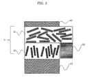
- FIG. 3 is a cross-section view of another structure of a heat conductor according to the embodiment.
- FIG. 1 is a cross-section view of a structure of heat conductor 3 according to an embodiment. As illustrated in FIG. 1 , flake graphite fillers 1 are oriented to two directions for respective layers in matrix resin 2 of heat conductor 3 . Heat conductor 3 has a double-layered structure. Here, “flake” means a thin strip or a curved plate.
- orientation angle ⁇ will be described hereinafter with reference to FIG. 1 .
- Sheet surfaces abbreviated as S and indicated by dotted lines are arbitrary and parallel to the line indicating the laminated surface of heat conductor 3 (laminate).
- Each of the dotted lines and a line indicating a surface of flake graphite filler 1 form orientation angle ⁇ .
- the surface of flake graphite filler 1 is indicated by basal plane B, and orientation angle ⁇ may be defined as an angle between basal plane B and the laminated surface of heat conductor 3 .
- FIG. 1 is a cross-section view of heat conductor 3 . Since flake graphite fillers 1 are uniformly distributed in heat conductor 3 , the same holds true for the other cross-sections of heat conductor 3 .
- Orientation angle ⁇ is calculated in the following manner. A cross-section of heat conductor 3 as illustrated in FIG. 1 is observed. Next, orientation angles ⁇ of more than 20 flake graphite fillers 1 in the cross-section are measured and averaged. The average is defined as orientation angle ⁇ . In other words, orientation angle ⁇ is defined as an average of the angles of all flake graphite fillers 1 . The same also holds for the following angles ⁇ .
- orientation angle ⁇ is an acute angle between the intersecting lines.
- orientation angle ⁇ ranges from 0 degree to 90 degrees.
- orientation angle ⁇ is defined by averaging orientation angles ⁇ in a cross-section.
- flake graphite fillers 1 are horizontally oriented in upper layer 31 (first layer).
- Orientation angle ⁇ (first angle) of flake graphite fillers 1 in upper layer 31 is 35 degrees or smaller. Such arrangement ensures the electric conductivity, and enables heat conductor 3 to exhibit the electromagnetic shielding effect as a whole.
- Orientation angle ⁇ suitably falls within 30 degrees.
- Setting orientation angle ⁇ in upper layer 31 higher than 1 degree can adequately secure the number of contact points of flake graphite fillers 1 , thus resulting in heat conductor 3 having higher thermal conductivity. Furthermore, setting orientation angle ⁇ of flake graphite fillers 1 within 35 degrees enable flake graphite fillers 1 to be oriented enough to increase the thermal conductivity in a surface direction of heat conductor 3 . In contrast, the thermal conductivity in a thickness direction of heat conductor 3 is suppressed. Thus, orientation angle ⁇ needs to be set within 35 degrees to ensure the thermal conductivity.
- Flake graphite fillers 1 are vertically oriented in lower layer 32 (second layer) of heat conductor 3 .
- Orientation angle ⁇ (second angle) in lower layer 32 ranges from 55 degrees to 90 degrees.
- heat conductor 3 has a compression set as a whole.
- flake graphite fillers 1 hardly spread across the boundary between upper layer 31 and lower layer 32 of heat conductor 3 .
- the boundary is clearly separated at the interface between these layers.
- upper and lower surfaces of upper layer 31 and lower layer 32 are parallel to the laminated surface of heat conductor 3 (laminate).
- FIG. 2 schematically illustrates flake graphite filler 1 .
- longer length “a” indicates the maximum length of flake graphite filler 1 in an arrow direction of “a” on basal plane B of flake graphite filler 1 .
- Flake graphite fillers 1 may have a lower orientation degree in heat conductor 3 when longer length “a” is smaller than or equal to 5 ⁇ m on average in preparing heat conductor 3 .
- longer length “a” is larger than or equal to 300 ⁇ m on average, the dispersibility may decrease.
- Shorter length “b” indicates the maximum length of flake graphite filler 1 perpendicular to longer length “a” on basal plane B.
- Thickness “c” indicates the maximum thickness of flake graphite filler 1 in a direction vertical to basal plane B as illustrated in FIG. 2 .
- the ratio (a/c) of longer length “a” to thickness “c” of flake graphite filler 1 is suitably 30 or higher on average.
- a/c is smaller than 30 on average, the number of contact points between flake graphite fillers 1 is reduced, and the thermal conductivity decreases.
- an average ratio (a/b) of longer length “a” to shorter length “b” suitably ranges from 1 to 30.
- the average ratio of a/b exceeds 30, the shape of flake graphite fillers 1 in heat conductor 3 cannot be maintained.
- Flake graphite fillers 1 having such a shape have suitable contacts in-between, and the thermal conductivity increases.
- the shape of flake graphite filler 1 described above is an example, and not necessarily limited to this.
- flake graphite fillers When flake graphite fillers have such a unique shape and are oriented in one direction, it is highly possible that flake graphite fillers 1 may be in contact with each other. Furthermore, the contact areas of flake graphite fillers may increase. Thus, the conductive path can be efficiently formed, and the electromagnetic shielding effect can be increased.
- orientation angle ⁇ between basal plane B and the surface direction of heat conductor 3 is set within 35 degrees on average, higher electromagnetic shielding effect can be observed.
- flake graphite fillers 1 When orientation angle ⁇ is set from 55 degrees to 90 degrees on average, flake graphite fillers 1 function as a spring in the rubber composition, and becomes a rubber molded product having a compression set.
- the rubber molded product exhibiting the higher electromagnetic shielding effect and having a better compression set can be obtained by laminating layers oriented in two directions, as upper layer 31 and lower layer 32 of heat conductor 3 in FIG. 1 .
- Flake graphite fillers 1 in each of upper layer 31 and lower layer 32 are set to account for more than 50% to 80% of heat conductor 3 by mass.
- the layers with such content exhibit the high electromagnetic shielding effect and have a compression set.
- flake graphite fillers 1 in upper layer 31 account for 50% or lower of heat conductor 3 by mass, the amount of flake graphite fillers 1 for electromagnetic shielding is insufficient, and the electromagnetic shielding effect may decrease.
- flake graphite fillers 1 in upper layer 31 account for 80% or higher of heat conductor 3 by mass, the amount of flake graphite fillers 1 in the resulting polymer is excessive, and the polymer becomes very brittle.
- flake graphite fillers 1 in lower layer 32 account for 50% or lower of heat conductor 3 by mass, the amount of flake graphite fillers 1 that produce restoring force against compression is insufficient, and the compression set becomes poor.
- flake graphite fillers 1 in lower layer 32 account for 80% or higher of heat conductor 3 by mass, the resulting polymer becomes very brittle as upper layer 31 .
- the two layers in heat conductor 3 may be any as long as the proportion of upper layer 31 to lower layer 32 in thickness ranges from 40% to 60%. When the proportion of upper layer 31 falls below 40% or exceeds 60%, the electromagnetic shielding effect and the compression properties becomes unbalanced and incompatible.
- Upper layer 31 and lower layer 32 are laminated (compressed) with the same surface area.
- Upper layer 31 may be larger than lower layer 32 in the other portions to dissipate heat.
- FIG. 3 is a cross-section view of such a case.
- Heat conductor 3 is disposed between lid 50 and main unit 51 .
- Upper layer 31 is larger than lower layer 32 , and the edge portion of upper layer 31 is connected to heat dissipator 52 .
- upper layer 31 and lower layer 32 are changed depending on the respective positions. However, each of upper layer 31 and lower layer 32 requires a thickness of at least 1 mm to fulfill their functions.
- the ratio of upper layer 31 to lower layer 32 in thickness is suitably 1:1, the quotient of upper layer 31 may range from 0.5 to 2.
- Heat conductor 3 is suitable as a shielding material to prevent malfunction of an electronic device caused by the electromagnetic waves from the outside, that is, electromagnetic interference (EMI).
- EMI electromagnetic interference
- heat conductor 3 The constituent elements of heat conductor 3 according to the embodiment will be more specifically described hereinafter.
- Flake graphite fillers whose longer length “a” ranges from 5 ⁇ m to 300 ⁇ m and a/c ratio is 30 or higher on average can be obtained by, for example, milling a graphite film. Alternatively, natural graphite may be processed into flakes whose longer length “a” ranges from 5 ⁇ m to 300 ⁇ m and a/c ratio is 30 or higher on average. Flake graphite fillers 1 of one kind may be solely used, or flake graphite fillers 1 obtained by mixing multiple kinds may be used as long as longer length “a” and the a/c ratio satisfy the above conditions.
- the graphite film can be obtained by graphitizing a polymer film through sintering it at a temperature of 2,400° C. or higher and suitably 2,600° C. to 3,000° C. in an inert gas atmosphere.
- the graphite film may be sintered in a single step or in two or more steps by changing the respective temperatures.
- Suitable examples of the inert gas include nitrogen or argon due to the low cost.
- Suitable examples of the sintering time include a period from 2 hours to 6 hours.
- the thickness of the polymer film to be graphitized may be selected as appropriate in accordance with thickness “c” of flake graphite fillers 1 .
- Examples of the thickness include 400 ⁇ m or smaller and suitably ranging from 10 ⁇ m to 200 ⁇ m.
- the polymer film has a thickness larger than 400 ⁇ m, heat is less likely to be evenly applied to the film, thus reducing the crystallinity of the graphite. If the polymer film has a thickness smaller than 10 ⁇ m, the film is broken by the heat treatment.
- suitable materials of the polymer film include polyimide, polyamide-imide, polyoxadiazole, polybenzothiazole, polybenzobisthiazole, polybenzoxazole, polybenzobisthiazole, polyphenyleneisophthalamide, poly(m-phenylene benzimidazole), poly(phenylenebenzobisimidazole), polythiazole, and polyparaphenylene vinylene. These materials are, for example, formed into films.
- the preparation method is not particularly limited to the above. These materials may be used singly or in a combination of two or more.
- two or more different kinds of the films may be graphitized, milled, and then mixed; or two or more different kinds of the materials that are conjugated or alloyed in advance may be formed into films and then graphitized.
- graphite having superior properties can be obtained from polyimide films.
- the obtained graphite film is milled into flake graphite fillers.
- Suitable examples of the milling method include making graphite fillers to collide against one another or physically collide against a hard material serving as a medium. Examples of the method also include ball milling, nanomizing, and jet milling.
- the thickness of the graphite film to be milled may be selected as appropriate in accordance with thickness “c” of desired flake graphite fillers.
- the natural graphite is suitably pretreated by having it immersed in sulfuric acid and then heated, thereby causing the graphite layers to expand. After such pretreatment, shear force is applied to the expanded graphite, thereby accelerating exfoliation of the layers. As a result, flake graphite fillers having a higher a/c ratio can be easily obtained.
- Example components of matrix resin 2 include various thermoplastic resins and elastomers.
- a mixture of a thermoplastic resin having no rubber elasticity and an elastic elastomer may be used as matrix resin 2 .
- the elastic elastomer is suitably used as matrix resin 2 .
- thermoplastic resin examples include: styrene polymers such as styrene-acrylonitrile copolymer, styrene-maleic anhydride copolymer, and (meth)acrylic acid ester-styrene copolymer; rubber toughened polymers such as acrylonitrile butadiene styrene (ABS) and acrylonitrile-Ethylene-Styrene (AES) resins; olefin polymers such as polyethylene, polypropylene, ethylene-vinyl acetate copolymer, ethylene-vinyl alcohol copolymer, and chlorinated polyethylene; vinyl chloride polymers such as polyvinyl chloride, ethylene-vinyl chloride polymer, and polyvinylidene chloride; (meth)acrylic acid ester polymers such as polymethyl methacrylate; imide polymers such as polyamide, polyimide, polyamide-imide, and polyether-imide; polyester poly
- elastomer examples include chloroprene rubber, isoprene rubber, natural rubber, styrene-butadiene rubber, butadiene rubber, butyl rubber, ethylene propylene rubber, ethylene propylene diene monomer (M-class) (EPDM) rubber, nitrile rubber, urethane rubber, acrylic rubber, silicone rubber, fluorine rubber, and hydrogenated nitrile rubber. These materials may be used singly or in a combination of two or more.
- Heat conductor 3 of the embodiment may include various additives, in addition to flake graphite fillers 1 and matrix resin 2 .
- Various additives are used, particularly when heat conductor 3 is a rubber composition including an elastomer.
- the additives for the rubber composition include a crosslinker for crosslinking the rubber components, a carbon black (e.g., Ketjen black, acetylene black) for improving the mechanical strength of the rubber components, and a plasticizer to be used in moderate amount for adjusting rubber hardness.
- the other additives including a vulcanizing agent such as stearic acid, an antidegradant, oil, a lubricant, and inorganic fillers (e.g., silica fillers, alumina fillers) can be added to the anisotropic heat conductive compositions as appropriate.
- the examples of the additives include a flame retardant.
- crosslinker examples include a sulfur crosslinker (vulcanizing agent) and a peroxide.
- the crosslinker is suitably added to the anisotropic heat conductive compositions in moderate amount.
- a curing agent for curing silicone e.g., tertiary amines
- curing accelerators including zinc oxide and active zinc oxide may be added to the anisotropic heat conductive compositions in moderate amount.
- the flame retardant examples include an organic flame retardant, an inorganic flame retardant, and a reactive flame retardant.
- the retardants may be used singly or at least two of the retardants may be combined.
- the organic flame retardant include: halogen flame retardants such as a brominated epoxy compound, a brominated alkyltriazine compound, a brominated bisphenol epoxy resin, a brominated bisphenol phenoxy resin, a brominated bisphenol polycarbonate resin, a brominated polystyrene resin, a brominated crosslinked polystyrene resin, a brominated bisphenol cyanurate resin, a brominated polyphenylene ether, a decabromodiphenyl oxide, tetrabromobisphenol A, and an oligomer thereof; phosphoric acid esters such as trimethyl phosphate, triethyl phosphate, tripropyl phosphate, tributyl phosphate, tripentyl phosphate
- the retardants may be used singly or at least two of the retardants may be combined.
- inorganic flame retardant examples include aluminum hydroxide, antimony oxide, magnesium hydroxide, zinc borate, a zirconium compound, a molybdenum compound, zinc stannate, guanidine salt, a silicone compound, and a phosphazene compound.
- the retardants may be used singly or at least two of the retardants may be combined.
- the reactive flame retardant examples include tetrabromobisphenol A, dibromophenol glycidyl ether, brominated aromatic triazine, tribromophenol, tetrabromophthalate, tetrachlorophthalic anhydride, dibromoneopentyl glycol, poly(pentabromobenzyl polyacrylate), chlorendic acid (HET acid), chlorendic anhydride (HET anhydride), brominated phenol glycidyl ether, and dibromocresyl glycidyl ether.
- the retardants may be used singly or at least two of the retardants may be combined.
- the amount of the additives is suitably 30% or lower of the total amount of heat conductor 3 by mass. This is because the moderate amount of the additives maintains the quantitative balance between flake graphite fillers 1 and matrix resin 2 , thus enabling heat conductor 3 to easily maintain satisfactory heat conductivity and to easily secure the moldability and the strength.
- heat conductor 3 is prepared.
- the preparation method may be any as long as the components of matrix resin 2 , flake graphite fillers 1 , and the additives if necessary that are to be included in the anisotropic heat conductive composition are blended and kneaded in an appropriate order.
- the elastomer rubber component
- materials except the rubber crosslinking agent are first kneaded and then, the agent is added to avoid progression of the crosslinking of the rubber by the heat generated during the kneading.
- the raw materials are kneaded in, for example, roll milling.
- the anisotropic heat conductive compositions pass through a gap between a pair of rollers to form heat conductors.
- shear force produced by the rotating rollers is applied to the compositions, and the compositions are elongated in a direction parallel to the rotating direction of the rollers.
- flake graphite fillers 1 dispersed in the anisotropic heat conductive composition become oriented in the same direction.
- basal planes B of flake graphite fillers 1 are successfully oriented in the surface direction of heat conductor 3 .
- Increasing the degree of orientation of flake graphite fillers 1 requires heat conductor 3 to pass through the rollers multiple times.
- heat conductor 3 is suitably separated from that roller, reversed, and then passes through the rollers again.
- the raw materials may be pre-kneaded by known kneaders, for example, a twin screw extruder, a single screw extruder, a twin or single screw feeder capable of applying heat, a feeder ruder, a Banbury mixer, and a roll mill.
- kneaders for example, a twin screw extruder, a single screw extruder, a twin or single screw feeder capable of applying heat, a feeder ruder, a Banbury mixer, and a roll mill.
- the anisotropic heat conductive composition is molded into heat conductor 3 with an intended thickness.
- the manner of molding heat conductor 3 is not particularly limited, as long as the thickness of heat conductor 3 can be adjusted.
- calendaring can produce a sufficient pressure to heat conductor 3 in the thickness direction. Furthermore, such a process enables basal planes B of flake graphite fillers 1 to be oriented in the surface direction of heat conductor 3 .
- the calendaring is suited to molding heat conductor 3 .
- the anisotropic heat conductive composition is continuously fed to at least a pair of rollers to form heat conductors 3 . Then, heat conductors 3 are wound up by a wind-up roll.
- the calendaring is suited to continuous production.
- the thickness of heat conductor 3 can be made more precise by hot rolling and then cold rolling the anisotropic heat conductive compositions in a preliminary process.
- the anisotropic heat conductive compositions may be extruded after it is sufficiently kneaded by an internal batch mixer such as a Banbury mixer.
- a anisotropic heat conductive compositions are continuously pushed out of a metal nozzle or a die that matches with the shape of heat conductor 3 , thereby to form heat conductor 3 .
- shear force is applied to the anisotropic heat conductive composition in the extrusion direction, thus causing basal planes B of flake graphite fillers 1 to be oriented in the surface direction of heat conductor 3 .
- Extruded heat conductor 3 may further be pressed between calendar rolls.
- the anisotropic heat conductive composition includes a rubber component
- it is heated as necessary to promote the crosslinking (vulcanization) by the crosslinker, thereby to obtain heat conductor 3 with excellent flexibility and strength.
- heat conductor 3 is cut in a direction perpendicular to its plane and rotated 90 degrees, thereby to obtain heat conductor 3 in which flake graphite fillers 1 are oriented in the thickness direction.
- upper layer 31 in FIG. 1 is first prepared in the above methods. Here, crosslinking the rubber component is stopped during the reaction.
- lower layer 32 of heat conductor 3 in which flake graphite fillers 1 are vertically oriented is laminated on upper layer 31 .
- lower layer 32 and upper layer 31 are heated to produce heat conductor 3 ( FIG. 1 ) having different two orientation directions of flake graphite fillers 1 .
- a polyimide film (Kapton film manufactured by Du Pont-Toray Co., Ltd.) 25 ⁇ m in thickness was heat treated for 4 hours at 2,600° C. in an argon gas atmosphere, thereby to obtain a graphite film.
- the obtained graphite film was then milled by a jet mill for 15 minutes.
- the number of rotations by the classifier during the milling was 7,000.
- flake graphite fillers 1 each having the following shape were obtained.
- the longer length “a” was 17 ⁇ m on average.
- Table 1 shows the obtained anisotropic heat conductive compositions.
- the anisotropic heat conductive compositions were further heated at 170° C. for five minutes to accelerate the vulcanization. Then, the anisotropic heat conductive compositions oriented in the horizontal and thickness directions were bonded together and heated at 170° C. for five minutes to form heat conductors 3 . Table 1 also shows the evaluation results.
- heat conductor 3 includes two layers, that is, upper layer 31 in which flake graphite fillers 1 are oriented within 35 degrees with respect to a horizontal (surface) direction of heat conductor 3 and lower layer 32 in which flake graphite fillers 1 are oriented within a range from 55 degrees to 80 degrees with respect to the same.
- Heat conductor 3 in each of comparative examples 1 and 2 is a single layer.
- Upper layer 31 and lower layer 32 each have a thickness of 2 mm.
- the shielding effect of obtained heat conductors 3 was measured by a waveguide method.
- the samples of 1 mm in thickness were measured in a frequency range from 18 GHz to 25 GHz, and evaluated at a frequency of 20 GHz.
- Heat conductors 3 of 25 dB or higher were accepted as exhibiting the shielding effect.
- Heat conductors 3 lower than 25 dB do not exhibit the shielding effect.
- the electromagnetic waves radiated from other electronic devices enter the current device and cause the device to malfunction.
- the compression set was measured at 70° C. after 100 hours in accordance with JIS K 6262. Heat conductors 3 having a compression set within 30% were accepted. When heat conductors 3 having a compression set exceeding 30% are used as gaskets or others, the restoring force and the shielding effect are lost.
- heat conductor 3 in Example 5 marginally satisfies the criterion on the shielding effect, it was marked ⁇ . Since heat conductor 3 in Example 6 marginally satisfies the criterion on the compression set, it was marked ⁇ . Since heat conductors 3 in Examples 1 to 4 sufficiently satisfy the criteria, they were marked ⁇ +.
- Table 1 indicates that heat conductor 3 in which flake graphite fillers 1 are horizontally oriented in Comparative example 1 exhibited the higher shielding effect. However, heat conductor 3 of Comparative example 1 exhibited a poor compression set. Conversely, heat conductor 3 in which flake graphite fillers 1 are vertically oriented in Comparative example 2 exhibited a better compression set. However, heat conductor 3 of Comparative example 2 exhibited the poor shielding effect.
- heat conductors 3 including upper layer 31 and lower layer 32 according to Examples 1 to 6 each exhibited the higher shielding effect and a better compression set.
- heat conductors 3 including (i) upper layer 31 in which flake graphite fillers 1 are oriented within a range from 10 degrees to 35 degrees and (ii) lower layer 32 in which flake graphite fillers 1 are oriented within a range from 55 degrees to 80 degrees with respect to the horizontal (surface) direction according to Examples 1 to 6 satisfy both of the properties.
- heat conductor 3 having a structure of two layers, that is, upper layer 31 in which flake graphite fillers 1 are oriented within the range from 10 degrees to 35 degrees and lower layer 32 in which flake graphite fillers 1 are oriented within the range from 55 degrees to 80 degrees satisfy both of the properties.
- Preparing heat conductors 3 each obtained by laminating the respective layers succeeded in having the two properties of the electromagnetic shielding effect and a compression set.
- flake graphite fillers 1 are averaged in the Specification, when the number of flake graphite fillers 1 is less and at least one of flake graphite fillers 1 satisfies the dimensions defined above, the present disclosure holds.
- Heat conductor 3 having the two layers may have more than two layers. In other words, heat conductor 3 may be any as long as it has at least two kinds of layers.
- the heat conductor is suitable for sealants.
- the expectation based on such properties is that the heat conductor is applicable to fiber-reinforced components, heat dissipating components, phase change components, photoluminescent pattern components, gas barrier components, conductive components, insulating components, components of low linear expansion coefficients, and methods for manufacturing these components.
Abstract
A heat conductor includes a first layer containing a first resin component and first flake graphite fillers each having a basal plane; and a second layer containing a second resin component and second flake graphite fillers each having a basal plane. The heat conductor is a laminate including the first layer and the second layer, an average of first angles in the first layer is 35 degrees or smaller, each of the first angles is an acute angle between the basal plane of a corresponding one of the first flake graphite fillers and a first laminated surface of the laminate, an average of second angles in the second layer ranges from 55 degrees to 90 degrees, and each of the second angles is an acute angle between the basal plane of a corresponding one of the second flake graphite fillers and a second laminated surface of the laminate.
Description
The present application is based on and claims priority of Japanese Patent Application No. 2014-101926 filed on May 16, 2014. The entire disclosure of the above-identified application, including the specification, drawings and claims is incorporated herein by reference in its entirety.
1. Field of the Invention
The present disclosure relates to a heat conductor and a device including the heat conductor, and particularly to a heat conductor in a rubber composition for shielding electromagnetic waves and to a device including the heat conductor.
2. Description of the Related Art
In recent years, electronic devices have been miniaturized and achieved greater functionality in many fields of, for example, households, offices, industries, and health care. The electromagnetic waves radiated from, for example, enclosures of electronic devices sometimes enter other electronic devices and cause the other electronic devices to malfunction.
As such, electronic devices malfunction due to electromagnetic waves from the outside. Thus, to prevent such malfunction, for example, the electronic devices are covered with electromagnetic wave shielding materials so that electromagnetic waves do not enter the electronic devices.
Conventional examples of the electromagnetic wave shielding materials include metal plates such as aluminum plates, metal-fiber wire meshes made of, for example, stainless-steel, plating films, and materials each having a surface treated to be conductive. These materials are separately used according to the application or the cost. Furthermore, the examples of the electromagnetic wave shielding materials also include a rubber material containing carbon for conductivity. This rubber material produces advantages of low cost, durability, and adding sealability to a part to which the rubber material is attached (Japanese Patent No. 4759852).
Since the electromagnetic wave shielding materials including this rubber material are used in a compressed state for a long period of time, they require not only sufficient conductivity but also excellent compression restorability as mechanical properties, that is, a low compression set. However, an electromagnetic wave shielding material containing a smaller amount of a filler for maintaining the rubber properties exhibits insufficient electromagnetic shielding effect. Thus, the electromagnetic wave shielding materials including this rubber material require the compatibility between the rubber properties and the electromagnetic shielding effect.
For example, JP 4759852 suggests that a rubber material containing a plasticizer, graphite fillers, and a reinforcing agent satisfies the compatibility between the rubber properties and the electromagnetic shielding effect.
The electromagnetic wave shielding materials including the rubber materials containing fillers linearly improve the electromagnetic shielding effect almost in proportion to the amount of the fillers. In other words, as the amount of the fillers increases, the electromagnetic shielding effect of the electromagnetic wave shielding materials is increased.
However, the increased amount of the fillers reduces the moldability of the electromagnetic wave shielding materials. As a result, the electromagnetic wave shielding materials are hardened, and the rubber elasticity decreases.
As described in JP 4759852, a composition in which graphite fillers are dispersed into a matrix of a thermoplastic resin has limitations in improvement in the electromagnetic shielding effect.
Thus, the present disclosure aims at providing a heat conductor containing graphite fillers, having electromagnetic wave properties, and having superior elasticity.
One non-limiting and exemplary embodiment provides a heat conductor including: a first layer containing a first resin component and a plurality of flake graphite fillers each having a basal plane; and a second layer containing a second resin component and the plurality of flake graphite fillers, wherein the heat conductor is a laminate including the first layer and the second layer, an average of first angles in the first layer is 35 degrees or smaller, each of the first angles being an acute angle between the basal plane of a corresponding one of the flake graphite fillers and a laminated surface of the laminate, and an average of second angles in the second layer ranges from 55 degrees to 90 degrees, each of the second angles being an acute angle between the basal plane of a corresponding one of the flake graphite fillers and the laminated surface of the laminate.
These and other objects, advantages and features of the disclosure will become apparent from the following description thereof taken in conjunction with the accompanying drawings that illustrate a specific embodiment of the present disclosure.
An embodiment will be described hereinafter.
The definition of orientation angle θ will be described hereinafter with reference to FIG. 1 . Sheet surfaces abbreviated as S and indicated by dotted lines are arbitrary and parallel to the line indicating the laminated surface of heat conductor 3 (laminate). Each of the dotted lines and a line indicating a surface of flake graphite filler 1 form orientation angle θ. The surface of flake graphite filler 1 is indicated by basal plane B, and orientation angle θ may be defined as an angle between basal plane B and the laminated surface of heat conductor 3. FIG. 1 is a cross-section view of heat conductor 3. Since flake graphite fillers 1 are uniformly distributed in heat conductor 3, the same holds true for the other cross-sections of heat conductor 3.
Orientation angle θ is calculated in the following manner. A cross-section of heat conductor 3 as illustrated in FIG. 1 is observed. Next, orientation angles θ of more than 20 flake graphite fillers 1 in the cross-section are measured and averaged. The average is defined as orientation angle θ. In other words, orientation angle θ is defined as an average of the angles of all flake graphite fillers 1. The same also holds for the following angles θ.
Here, orientation angle θ is an acute angle between the intersecting lines. Thus, orientation angle θ ranges from 0 degree to 90 degrees.
The angles between surfaces vary depending on each of the cross-sections. Here, orientation angle θ is defined by averaging orientation angles θ in a cross-section.
In FIG. 1 , flake graphite fillers 1 are horizontally oriented in upper layer 31 (first layer). Orientation angle θ (first angle) of flake graphite fillers 1 in upper layer 31 is 35 degrees or smaller. Such arrangement ensures the electric conductivity, and enables heat conductor 3 to exhibit the electromagnetic shielding effect as a whole. Orientation angle θ suitably falls within 30 degrees.
Setting orientation angle θ in upper layer 31 higher than 1 degree can adequately secure the number of contact points of flake graphite fillers 1, thus resulting in heat conductor 3 having higher thermal conductivity. Furthermore, setting orientation angle θ of flake graphite fillers 1 within 35 degrees enable flake graphite fillers 1 to be oriented enough to increase the thermal conductivity in a surface direction of heat conductor 3. In contrast, the thermal conductivity in a thickness direction of heat conductor 3 is suppressed. Thus, orientation angle θ needs to be set within 35 degrees to ensure the thermal conductivity.
Here, flake graphite fillers 1 hardly spread across the boundary between upper layer 31 and lower layer 32 of heat conductor 3. The boundary is clearly separated at the interface between these layers. Here, upper and lower surfaces of upper layer 31 and lower layer 32 are parallel to the laminated surface of heat conductor 3 (laminate).
As illustrated in FIG. 2 , longer length “a” indicates the maximum length of flake graphite filler 1 in an arrow direction of “a” on basal plane B of flake graphite filler 1. Flake graphite fillers 1 may have a lower orientation degree in heat conductor 3 when longer length “a” is smaller than or equal to 5 μm on average in preparing heat conductor 3. When longer length “a” is larger than or equal to 300 μm on average, the dispersibility may decrease.
Shorter length “b” indicates the maximum length of flake graphite filler 1 perpendicular to longer length “a” on basal plane B.
Thickness “c” indicates the maximum thickness of flake graphite filler 1 in a direction vertical to basal plane B as illustrated in FIG. 2 .
The ratio (a/c) of longer length “a” to thickness “c” of flake graphite filler 1 is suitably 30 or higher on average. When a/c is smaller than 30 on average, the number of contact points between flake graphite fillers 1 is reduced, and the thermal conductivity decreases.
Furthermore, when shorter length “b” indicates the maximum length of flake graphite filler 1 perpendicular to longer length “a” on basal plane B, an average ratio (a/b) of longer length “a” to shorter length “b” suitably ranges from 1 to 30. When the average ratio of a/b exceeds 30, the shape of flake graphite fillers 1 in heat conductor 3 cannot be maintained.
When flake graphite fillers have such a unique shape and are oriented in one direction, it is highly possible that flake graphite fillers 1 may be in contact with each other. Furthermore, the contact areas of flake graphite fillers may increase. Thus, the conductive path can be efficiently formed, and the electromagnetic shielding effect can be increased.
When orientation angle θ between basal plane B and the surface direction of heat conductor 3 is set within 35 degrees on average, higher electromagnetic shielding effect can be observed.
When orientation angle θ is set from 55 degrees to 90 degrees on average, flake graphite fillers 1 function as a spring in the rubber composition, and becomes a rubber molded product having a compression set.
The rubber molded product exhibiting the higher electromagnetic shielding effect and having a better compression set can be obtained by laminating layers oriented in two directions, as upper layer 31 and lower layer 32 of heat conductor 3 in FIG. 1 .
When flake graphite fillers 1 in upper layer 31 account for 50% or lower of heat conductor 3 by mass, the amount of flake graphite fillers 1 for electromagnetic shielding is insufficient, and the electromagnetic shielding effect may decrease. When flake graphite fillers 1 in upper layer 31 account for 80% or higher of heat conductor 3 by mass, the amount of flake graphite fillers 1 in the resulting polymer is excessive, and the polymer becomes very brittle.
When flake graphite fillers 1 in lower layer 32 account for 50% or lower of heat conductor 3 by mass, the amount of flake graphite fillers 1 that produce restoring force against compression is insufficient, and the compression set becomes poor. When flake graphite fillers 1 in lower layer 32 account for 80% or higher of heat conductor 3 by mass, the resulting polymer becomes very brittle as upper layer 31.
The two layers in heat conductor 3 may be any as long as the proportion of upper layer 31 to lower layer 32 in thickness ranges from 40% to 60%. When the proportion of upper layer 31 falls below 40% or exceeds 60%, the electromagnetic shielding effect and the compression properties becomes unbalanced and incompatible.
Such properties can be exhibited when upper layer 31 and lower layer 32 are laminated (compressed) with the same surface area. Upper layer 31 may be larger than lower layer 32 in the other portions to dissipate heat.
For example, FIG. 3 is a cross-section view of such a case. Heat conductor 3 is disposed between lid 50 and main unit 51. Upper layer 31 is larger than lower layer 32, and the edge portion of upper layer 31 is connected to heat dissipator 52.
Since upper layer 31 protrudes in the portion other than the laminated (compressed) portion, the heat can be dissipated into heat dissipator 52.
The thicknesses of upper layer 31 and lower layer 32 are changed depending on the respective positions. However, each of upper layer 31 and lower layer 32 requires a thickness of at least 1 mm to fulfill their functions.
Although the ratio of upper layer 31 to lower layer 32 in thickness is suitably 1:1, the quotient of upper layer 31 may range from 0.5 to 2.
The constituent elements of heat conductor 3 according to the embodiment will be more specifically described hereinafter.
Flake graphite fillers whose longer length “a” ranges from 5 μm to 300 μm and a/c ratio is 30 or higher on average can be obtained by, for example, milling a graphite film. Alternatively, natural graphite may be processed into flakes whose longer length “a” ranges from 5 μm to 300 μm and a/c ratio is 30 or higher on average. Flake graphite fillers 1 of one kind may be solely used, or flake graphite fillers 1 obtained by mixing multiple kinds may be used as long as longer length “a” and the a/c ratio satisfy the above conditions.
The graphite film can be obtained by graphitizing a polymer film through sintering it at a temperature of 2,400° C. or higher and suitably 2,600° C. to 3,000° C. in an inert gas atmosphere. The graphite film may be sintered in a single step or in two or more steps by changing the respective temperatures. Suitable examples of the inert gas include nitrogen or argon due to the low cost. Suitable examples of the sintering time include a period from 2 hours to 6 hours.
The thickness of the polymer film to be graphitized may be selected as appropriate in accordance with thickness “c” of flake graphite fillers 1. Examples of the thickness include 400 μm or smaller and suitably ranging from 10 μm to 200 μm. When a comparatively thick polymer film is graphitized as a starting material and the resulting graphite film is milled, the graphite layers exfoliate. Thus, thinner flake graphite fillers can be obtained.
If the polymer film has a thickness larger than 400 μm, heat is less likely to be evenly applied to the film, thus reducing the crystallinity of the graphite. If the polymer film has a thickness smaller than 10 μm, the film is broken by the heat treatment.
Examples of suitable materials of the polymer film include polyimide, polyamide-imide, polyoxadiazole, polybenzothiazole, polybenzobisthiazole, polybenzoxazole, polybenzobisthiazole, polyphenyleneisophthalamide, poly(m-phenylene benzimidazole), poly(phenylenebenzobisimidazole), polythiazole, and polyparaphenylene vinylene. These materials are, for example, formed into films.
The preparation method is not particularly limited to the above. These materials may be used singly or in a combination of two or more. For example, two or more different kinds of the films may be graphitized, milled, and then mixed; or two or more different kinds of the materials that are conjugated or alloyed in advance may be formed into films and then graphitized. Particularly, graphite having superior properties can be obtained from polyimide films.
The obtained graphite film is milled into flake graphite fillers. Suitable examples of the milling method include making graphite fillers to collide against one another or physically collide against a hard material serving as a medium. Examples of the method also include ball milling, nanomizing, and jet milling.
The thickness of the graphite film to be milled may be selected as appropriate in accordance with thickness “c” of desired flake graphite fillers.
In processing natural graphite, the natural graphite is suitably pretreated by having it immersed in sulfuric acid and then heated, thereby causing the graphite layers to expand. After such pretreatment, shear force is applied to the expanded graphite, thereby accelerating exfoliation of the layers. As a result, flake graphite fillers having a higher a/c ratio can be easily obtained.
Example components of matrix resin 2 include various thermoplastic resins and elastomers. Alternatively, a mixture of a thermoplastic resin having no rubber elasticity and an elastic elastomer may be used as matrix resin 2. Particularly, the elastic elastomer is suitably used as matrix resin 2.
Examples of the thermoplastic resin include: styrene polymers such as styrene-acrylonitrile copolymer, styrene-maleic anhydride copolymer, and (meth)acrylic acid ester-styrene copolymer; rubber toughened polymers such as acrylonitrile butadiene styrene (ABS) and acrylonitrile-Ethylene-Styrene (AES) resins; olefin polymers such as polyethylene, polypropylene, ethylene-vinyl acetate copolymer, ethylene-vinyl alcohol copolymer, and chlorinated polyethylene; vinyl chloride polymers such as polyvinyl chloride, ethylene-vinyl chloride polymer, and polyvinylidene chloride; (meth)acrylic acid ester polymers such as polymethyl methacrylate; imide polymers such as polyamide, polyimide, polyamide-imide, and polyether-imide; polyester polymers such as polyethylene terephthalate and polybutylene terephthalate; polyacetal; polycarbonate; polyarylate; polyphenylene ether; polyphenylene sulfide; fluororesins such as polytetrafluoroethylene and polyvinylidene fluoride; ketone polymers such as polyetherketone and polyether ether ketone; sulfone polymers such as polysulfone and polyethersulfone; urethane polymers; and polyvinyl acetate. These materials may be used singly or in a combination of two or more. Furthermore, some of these materials may be alloyed.
Examples of the elastomer include chloroprene rubber, isoprene rubber, natural rubber, styrene-butadiene rubber, butadiene rubber, butyl rubber, ethylene propylene rubber, ethylene propylene diene monomer (M-class) (EPDM) rubber, nitrile rubber, urethane rubber, acrylic rubber, silicone rubber, fluorine rubber, and hydrogenated nitrile rubber. These materials may be used singly or in a combination of two or more.
Examples of the crosslinker include a sulfur crosslinker (vulcanizing agent) and a peroxide. The crosslinker is suitably added to the anisotropic heat conductive compositions in moderate amount. When a silicone rubber is used in matrix resin 2, a curing agent for curing silicone (e.g., tertiary amines) is suitably added. Moreover, curing accelerators including zinc oxide and active zinc oxide may be added to the anisotropic heat conductive compositions in moderate amount.
Examples of the flame retardant include an organic flame retardant, an inorganic flame retardant, and a reactive flame retardant. The retardants may be used singly or at least two of the retardants may be combined. Examples of the organic flame retardant include: halogen flame retardants such as a brominated epoxy compound, a brominated alkyltriazine compound, a brominated bisphenol epoxy resin, a brominated bisphenol phenoxy resin, a brominated bisphenol polycarbonate resin, a brominated polystyrene resin, a brominated crosslinked polystyrene resin, a brominated bisphenol cyanurate resin, a brominated polyphenylene ether, a decabromodiphenyl oxide, tetrabromobisphenol A, and an oligomer thereof; phosphoric acid esters such as trimethyl phosphate, triethyl phosphate, tripropyl phosphate, tributyl phosphate, tripentyl phosphate, trihexyl phosphate, tricyclohexyl phosphate, triphenyl phosphate, tricresyl phosphate, trixylenyl phosphate, cresyl diphenyl phosphate, dicresyl phenyl phosphate, dimethyl ethyl phosphate, methyl dibutyl phosphate, ethyl dipropyl phosphate, and hydroxyphenyl diphenyl phosphate; compounds obtained by denaturing these phosphoric acid esters by various substituents; various condensed phosphoric acid ester compounds; phosphorous flame retardants such as phosphazene derivatives including phosphorus and nitrogen; and polytetrafluoroethylene.
The retardants may be used singly or at least two of the retardants may be combined.
Examples of the inorganic flame retardant include aluminum hydroxide, antimony oxide, magnesium hydroxide, zinc borate, a zirconium compound, a molybdenum compound, zinc stannate, guanidine salt, a silicone compound, and a phosphazene compound. The retardants may be used singly or at least two of the retardants may be combined.
Examples of the reactive flame retardant include tetrabromobisphenol A, dibromophenol glycidyl ether, brominated aromatic triazine, tribromophenol, tetrabromophthalate, tetrachlorophthalic anhydride, dibromoneopentyl glycol, poly(pentabromobenzyl polyacrylate), chlorendic acid (HET acid), chlorendic anhydride (HET anhydride), brominated phenol glycidyl ether, and dibromocresyl glycidyl ether. The retardants may be used singly or at least two of the retardants may be combined.
The amount of the additives is suitably 30% or lower of the total amount of heat conductor 3 by mass. This is because the moderate amount of the additives maintains the quantitative balance between flake graphite fillers 1 and matrix resin 2, thus enabling heat conductor 3 to easily maintain satisfactory heat conductivity and to easily secure the moldability and the strength.
First, heat conductor 3 is prepared. The preparation method may be any as long as the components of matrix resin 2, flake graphite fillers 1, and the additives if necessary that are to be included in the anisotropic heat conductive composition are blended and kneaded in an appropriate order.
However, when the elastomer (rubber component) is used as a resin component, it is suitable that materials except the rubber crosslinking agent are first kneaded and then, the agent is added to avoid progression of the crosslinking of the rubber by the heat generated during the kneading.
The raw materials are kneaded in, for example, roll milling. In the roll milling, the anisotropic heat conductive compositions pass through a gap between a pair of rollers to form heat conductors. As the anisotropic heat conductive compositions are sandwiched between the rollers and pass through the gap therebetween, shear force produced by the rotating rollers is applied to the compositions, and the compositions are elongated in a direction parallel to the rotating direction of the rollers. Along with the elongation of matrix resin 2, flake graphite fillers 1 dispersed in the anisotropic heat conductive composition become oriented in the same direction.
As a result, basal planes B of flake graphite fillers 1 are successfully oriented in the surface direction of heat conductor 3. Increasing the degree of orientation of flake graphite fillers 1 requires heat conductor 3 to pass through the rollers multiple times. Moreover, when heat conductor 3 sticks onto one of the rollers when coming out from the rollers, heat conductor 3 is suitably separated from that roller, reversed, and then passes through the rollers again.
Before kneading the anisotropic heat conductive composition in the roll milling, the raw materials may be pre-kneaded by known kneaders, for example, a twin screw extruder, a single screw extruder, a twin or single screw feeder capable of applying heat, a feeder ruder, a Banbury mixer, and a roll mill.
Next, the anisotropic heat conductive composition is molded into heat conductor 3 with an intended thickness. The manner of molding heat conductor 3 is not particularly limited, as long as the thickness of heat conductor 3 can be adjusted. Here, calendaring can produce a sufficient pressure to heat conductor 3 in the thickness direction. Furthermore, such a process enables basal planes B of flake graphite fillers 1 to be oriented in the surface direction of heat conductor 3. Thus, the calendaring is suited to molding heat conductor 3.
In the calendaring, the anisotropic heat conductive composition is continuously fed to at least a pair of rollers to form heat conductors 3. Then, heat conductors 3 are wound up by a wind-up roll. Thus, the calendaring is suited to continuous production. The thickness of heat conductor 3 can be made more precise by hot rolling and then cold rolling the anisotropic heat conductive compositions in a preliminary process.
Alternatively, the anisotropic heat conductive compositions may be extruded after it is sufficiently kneaded by an internal batch mixer such as a Banbury mixer. In the extrusion, a anisotropic heat conductive compositions are continuously pushed out of a metal nozzle or a die that matches with the shape of heat conductor 3, thereby to form heat conductor 3. During the extrusion, shear force is applied to the anisotropic heat conductive composition in the extrusion direction, thus causing basal planes B of flake graphite fillers 1 to be oriented in the surface direction of heat conductor 3. Extruded heat conductor 3 may further be pressed between calendar rolls.
When the anisotropic heat conductive composition includes a rubber component, it is heated as necessary to promote the crosslinking (vulcanization) by the crosslinker, thereby to obtain heat conductor 3 with excellent flexibility and strength. Thereafter, heat conductor 3 is cut in a direction perpendicular to its plane and rotated 90 degrees, thereby to obtain heat conductor 3 in which flake graphite fillers 1 are oriented in the thickness direction.
When heat conductor 3 in FIG. 1 is prepared, upper layer 31 in FIG. 1 is first prepared in the above methods. Here, crosslinking the rubber component is stopped during the reaction.
Then, lower layer 32 of heat conductor 3 in which flake graphite fillers 1 are vertically oriented is laminated on upper layer 31. Finally, lower layer 32 and upper layer 31 are heated to produce heat conductor 3 (FIG. 1 ) having different two orientation directions of flake graphite fillers 1.
(i) Preparing Flake Graphite Fillers 1
A polyimide film (Kapton film manufactured by Du Pont-Toray Co., Ltd.) 25 μm in thickness was heat treated for 4 hours at 2,600° C. in an argon gas atmosphere, thereby to obtain a graphite film. The obtained graphite film was then milled by a jet mill for 15 minutes. The number of rotations by the classifier during the milling was 7,000. As a result, flake graphite fillers 1 each having the following shape were obtained. The longer length “a” was 17 μm on average.
(ii) Preparation of Heat Conductor 3
Obtained flake graphite fillers 1, EPDM (Esprene manufactured by Sumitomo Chemical Co., Ltd.), a peroxide serving as a crosslinker, and stearic acid were mixed together. The resultant mixture was sufficiently kneaded by a two-roll mixer with 8-inch diameter rollers to prepare heat conductor 3; meanwhile, flake graphite fillers 1 in the anisotropic heat conductive composition were oriented in the surface direction.
Table 1 shows the obtained anisotropic heat conductive compositions. The anisotropic heat conductive compositions were further heated at 170° C. for five minutes to accelerate the vulcanization. Then, the anisotropic heat conductive compositions oriented in the horizontal and thickness directions were bonded together and heated at 170° C. for five minutes to form heat conductors 3. Table 1 also shows the evaluation results.
The anisotropic heat conductive compositions were prepared and molded according to the conditions in Table 1, as Examples 1 and 2. In each of Examples 1 to 6, heat conductor 3 includes two layers, that is, upper layer 31 in which flake graphite fillers 1 are oriented within 35 degrees with respect to a horizontal (surface) direction of heat conductor 3 and lower layer 32 in which flake graphite fillers 1 are oriented within a range from 55 degrees to 80 degrees with respect to the same. Heat conductor 3 in each of comparative examples 1 and 2 is a single layer. Upper layer 31 and lower layer 32 each have a thickness of 2 mm.
| TABLE 1 | |||
| COMPAR- | |||
| ATIVE | |||
| EXAMPLE | EXAMPLE | ||
| 1 | 2 | 3 | 4 | 5 | 6 | 1 | 2 | ||
| AMOUNT | 60 | 70 | 60 | 70 | 60 | 60 | 70 | 70 |
| OF | ||||||||
| GRAPHITE | ||||||||
| ORIENTA- | 10/80 | 10/80 | 30/60 | 30/60 | 35/80 | 10/55 | 10 | 80 |
| TION DE- | (SIN- | (SIN- | ||||||
| GREE (°) | GLE | GLE | ||||||
| (UPPER LAY- | LAY- | LAY- | ||||||
| |
ER) | ER) | ||||||
| ER LAYER | ||||||||
| 32) | ||||||||
| SHIELDING | 34 | 50 | 30 | 50 | 27 | 30 | 60 | 20 |
| EFFECT (DB) | ||||||||
| COMPRES- | 20 | 23 | 22 | 25 | 20 | 27 | 40 | 13 |
| SION SET (%) | ||||||||
| ACCEPT- | ✓+ | ✓+ | ✓+ | ✓+ | ✓ | ✓ | x | x |
| ABILITY | ||||||||
| x FAIL | ||||||||
| ✓ ACCEPTABLE | ||||||||
| ✓+ EXCELLENT | ||||||||
(1) Shielding Effect
The shielding effect of obtained heat conductors 3 was measured by a waveguide method. The samples of 1 mm in thickness were measured in a frequency range from 18 GHz to 25 GHz, and evaluated at a frequency of 20 GHz. Heat conductors 3 of 25 dB or higher were accepted as exhibiting the shielding effect. Heat conductors 3 lower than 25 dB do not exhibit the shielding effect. Thus, the electromagnetic waves radiated from other electronic devices enter the current device and cause the device to malfunction.
(2) Compression Set
The compression set was measured at 70° C. after 100 hours in accordance with JIS K 6262. Heat conductors 3 having a compression set within 30% were accepted. When heat conductors 3 having a compression set exceeding 30% are used as gaskets or others, the restoring force and the shielding effect are lost.
(3) Acceptability
Since heat conductor 3 in Example 5 marginally satisfies the criterion on the shielding effect, it was marked √. Since heat conductor 3 in Example 6 marginally satisfies the criterion on the compression set, it was marked √. Since heat conductors 3 in Examples 1 to 4 sufficiently satisfy the criteria, they were marked √+.
Table 1 indicates that heat conductor 3 in which flake graphite fillers 1 are horizontally oriented in Comparative example 1 exhibited the higher shielding effect. However, heat conductor 3 of Comparative example 1 exhibited a poor compression set. Conversely, heat conductor 3 in which flake graphite fillers 1 are vertically oriented in Comparative example 2 exhibited a better compression set. However, heat conductor 3 of Comparative example 2 exhibited the poor shielding effect.
In contrast, heat conductors 3 including upper layer 31 and lower layer 32 according to Examples 1 to 6 each exhibited the higher shielding effect and a better compression set.
Specifically, heat conductors 3 including (i) upper layer 31 in which flake graphite fillers 1 are oriented within a range from 10 degrees to 35 degrees and (ii) lower layer 32 in which flake graphite fillers 1 are oriented within a range from 55 degrees to 80 degrees with respect to the horizontal (surface) direction according to Examples 1 to 6 satisfy both of the properties.
According to Table 1, as orientation angle θ in upper layer 31 is smaller, the electromagnetic shielding effect is increased. Conversely, as orientation angle θ in lower layer 32 is larger, a better compression set is obtained.
Thus, heat conductor 3 having a structure of two layers, that is, upper layer 31 in which flake graphite fillers 1 are oriented within the range from 10 degrees to 35 degrees and lower layer 32 in which flake graphite fillers 1 are oriented within the range from 55 degrees to 80 degrees satisfy both of the properties.
Preparing heat conductors 3 each obtained by laminating the respective layers succeeded in having the two properties of the electromagnetic shielding effect and a compression set.
Although the dimensions of flake graphite fillers 1 are averaged in the Specification, when the number of flake graphite fillers 1 is less and at least one of flake graphite fillers 1 satisfies the dimensions defined above, the present disclosure holds.
Although only some exemplary embodiments of the present disclosure have been described in detail above, those skilled in the art will readily appreciate that many modifications are possible in the exemplary embodiments without materially departing from the novel teachings and advantages of the present disclosure. Accordingly, all such modifications are intended to be included within the scope of the present disclosure.
The electromagnetic shielding effect and having a compression set are compatible in the heat conductor according to the present disclosure. Thus, the heat conductor is suitable for sealants. The expectation based on such properties is that the heat conductor is applicable to fiber-reinforced components, heat dissipating components, phase change components, photoluminescent pattern components, gas barrier components, conductive components, insulating components, components of low linear expansion coefficients, and methods for manufacturing these components.
Claims (18)
1. A heat conductor comprising:
a first layer containing a first resin component and first flake graphite fillers each having a basal plane; and
a second layer containing a second resin component and second flake graphite fillers each having a basal plane,
wherein the heat conductor is a laminate including the first layer and the second layer,
wherein an average of first angles in the first layer is 35 degrees or smaller, each of the first angles being an acute angle between the basal plane of a corresponding one of the first flake graphite fillers and a first laminated surface of the laminate,
wherein an average of second angles in the second layer ranges from 55 degrees to 90 degrees, each of the second angles being an acute angle between the basal plane of a corresponding one of the second flake graphite fillers and the second laminated surface of the laminate,
wherein each of the first flake graphite fillers satisfies a ratio of a/c higher than or equal to 30 and “a” ranges from 1 μm to 300 μm on average, where “a” denotes a maximum length of the first flake graphite filler on the basal plane of the first flake graphite filler, and “c” denotes a maximum thickness of the first flake graphite filler, the maximum thickness of the first flake graphite filler being vertical to the basal plane of the first flake graphite filler, and
wherein each of the second flake graphite fillers satisfies a ratio of a/c higher than or equal to 30 and “a” ranges from 1 μm to 300 μm on average, where “a” denotes a maximum length of the second flake graphite filler on the basal plane of the second flake graphite filler, and “c” denotes a maximum thickness of the second flake graphite filler, the maximum thickness of the second flake graphite filler being vertical to the basal plane of the second flake graphite filler.
2. The heat conductor according to claim 1 ,
wherein upper and lower surfaces of the first layer are parallel to the first laminated surface of the laminate and upper and lower surfaces of the second layer are parallel to the second laminated surface of the laminate.
3. The heat conductor according to claim 1 ,
wherein the first layer and the second layer are separated at an interface.
4. The heat conductor according to claim 1 ,
wherein the average of the first angles is 30 degrees or smaller.
5. The heat conductor according to claim 1 ,
wherein the average of the second angles is 80 degrees or smaller.
6. The heat conductor according to claim 1 ,
wherein the first flake graphite fillers and the second flake graphite fillers account for more than 50% to 80% of the heat conductor by mass.
7. A heat conductor comprising:
a first layer containing a first resin component and first flake graphite fillers each having a basal plane; and
a second layer containing a second resin component and second flake graphite fillers each having a basal plane,
wherein the heat conductor is a laminate including the first layer and the second layer,
wherein an average of first angles in the first layer is 35 degrees or smaller, each of the first angles being an acute angle between the basal plane of a corresponding one of the first flake graphite fillers and a first laminated surface of the laminate,
wherein an average of second angles in the second layer ranges from 55 degrees to 90 degrees, each of the second angles being an acute angle between the basal plane of a corresponding one of the second flake graphite fillers and a second laminated surface of the laminate,
wherein each of the first flake graphite fillers satisfies a ratio of a/b ranging from 1 to 20 on average, where “a” denotes a maximum length of the first flake graphite filler on the basal plane of the first flake graphite filler, and “b” denotes a maximum length of the first flake graphite filler perpendicular to “a” on the basal plane of the first flake graphite filler, and
wherein each of the second flake graphite fillers satisfies a ratio of a/b ranging from 1 to 20 on average, where “a” denotes a maximum length of the second flake graphite filler on the basal plane of the second flake graphite filler, and “b” denotes a maximum length of the second flake graphite filler perpendicular to “a” on the basal plane of the second flake graphite filler.
8. The heat conductor according to claim 1 ,
wherein each of the first flake graphite fillers and the second flake graphite fillers is a heat-treated polymer film.
9. The heat conductor according to claim 8 ,
wherein the heat-treated polymer film is a polyimide film.
10. A device comprising:
a lid;
a main unit; and
the heat conductor according to claim 1 , wherein the heat conductor is between the lid and the main unit.
11. The heat conductor according to claim 7 ,
wherein upper and lower surfaces of the first layer are parallel to the first laminated surface of the laminate and upper and lower surfaces of the second layer are parallel to the second laminated surface of the laminate.
12. The heat conductor according to claim 7 ,
wherein the first layer and the second layer are separated at an interface.
13. The heat conductor according to claim 7 ,
wherein the average of the first angles is 30 degrees or smaller.
14. The heat conductor according to claim 7 ,
wherein the average of the second angles is 80 degrees or smaller.
15. The heat conductor according to claim 7 ,
wherein the first flake graphite fillers and the second flake graphite fillers account for more than 50% to 80% of the heat conductor by mass.
16. The heat conductor according to claim 7 ,
wherein each of the first flake graphite fillers and the second flake graphite fillers is a heat-treated polymer film.
17. The heat conductor according to claim 16 ,
wherein the heat-treated polymer film is a polyimide film.
18. A device comprising:
a lid;
a main unit; and
the heat conductor according to claim 7 , wherein the heat conductor is between the lid and the main unit.
Applications Claiming Priority (2)
| Application Number | Priority Date | Filing Date | Title |
|---|---|---|---|
| JP2014-101926 | 2014-05-16 | ||
| JP2014101926A JP6368910B2 (en) | 2014-05-16 | 2014-05-16 | Thermal conductor |
Publications (2)
| Publication Number | Publication Date |
|---|---|
| US20150330724A1 US20150330724A1 (en) | 2015-11-19 |
| US9746259B2 true US9746259B2 (en) | 2017-08-29 |
Family
ID=53181108
Family Applications (1)
| Application Number | Title | Priority Date | Filing Date |
|---|---|---|---|
| US14/713,306 Active 2035-12-15 US9746259B2 (en) | 2014-05-16 | 2015-05-15 | Heat conductor and device including the same |
Country Status (3)
| Country | Link |
|---|---|
| US (1) | US9746259B2 (en) |
| EP (1) | EP2945472B1 (en) |
| JP (1) | JP6368910B2 (en) |
Cited By (2)
| Publication number | Priority date | Publication date | Assignee | Title |
|---|---|---|---|---|
| US10462944B1 (en) * | 2018-09-25 | 2019-10-29 | Getac Technology Corporation | Wave absorbing heat dissipation structure |
| US11235557B2 (en) | 2018-06-07 | 2022-02-01 | Sht Smart High-Tech Ab | Graphene based heat sink and method for manufacturing the heat sink |
Families Citing this family (4)
| Publication number | Priority date | Publication date | Assignee | Title |
|---|---|---|---|---|
| CN111148943B (en) * | 2017-08-01 | 2022-07-01 | 昕诺飞控股有限公司 | Lighting device and method of manufacturing a lighting device |
| JP2019134011A (en) * | 2018-01-30 | 2019-08-08 | パナソニックIpマネジメント株式会社 | Electromagnetic wave absorption member |
| JP6379320B1 (en) * | 2018-07-03 | 2018-08-22 | デクセリアルズ株式会社 | Electromagnetic wave absorbing heat conducting sheet, method for producing electromagnetic wave absorbing heat conducting sheet, and semiconductor device |
| CN111070833B (en) * | 2019-12-10 | 2021-07-23 | 深圳先进技术研究院 | High-thermal-conductivity electromagnetic shielding composite material and preparation method thereof |
Citations (5)
| Publication number | Priority date | Publication date | Assignee | Title |
|---|---|---|---|---|
| US7168484B2 (en) * | 2003-06-30 | 2007-01-30 | Intel Corporation | Thermal interface apparatus, systems, and methods |
| US7416019B2 (en) * | 2003-08-13 | 2008-08-26 | The Johns Hopkins University | Thermal interface and switch using carbon nanotube arrays |
| JP4759852B2 (en) | 2001-06-01 | 2011-08-31 | Nok株式会社 | Rubber composition for electromagnetic wave shielding |
| US8194407B2 (en) * | 2008-11-14 | 2012-06-05 | Fujitsu Limited | Heat radiation material, electronic device and method of manufacturing electronic device |
| WO2013099089A1 (en) | 2011-12-27 | 2013-07-04 | パナソニック株式会社 | Anisotropic thermally conductive composition and molded article thereof |
Family Cites Families (1)
| Publication number | Priority date | Publication date | Assignee | Title |
|---|---|---|---|---|
| JP2012253167A (en) * | 2011-06-02 | 2012-12-20 | Denki Kagaku Kogyo Kk | Thermally conductive insulation sheet, metal base substrate and circuit board |
-
2014
- 2014-05-16 JP JP2014101926A patent/JP6368910B2/en active Active
-
2015
- 2015-05-13 EP EP15167663.2A patent/EP2945472B1/en active Active
- 2015-05-15 US US14/713,306 patent/US9746259B2/en active Active
Patent Citations (6)
| Publication number | Priority date | Publication date | Assignee | Title |
|---|---|---|---|---|
| JP4759852B2 (en) | 2001-06-01 | 2011-08-31 | Nok株式会社 | Rubber composition for electromagnetic wave shielding |
| US7168484B2 (en) * | 2003-06-30 | 2007-01-30 | Intel Corporation | Thermal interface apparatus, systems, and methods |
| US7416019B2 (en) * | 2003-08-13 | 2008-08-26 | The Johns Hopkins University | Thermal interface and switch using carbon nanotube arrays |
| US8194407B2 (en) * | 2008-11-14 | 2012-06-05 | Fujitsu Limited | Heat radiation material, electronic device and method of manufacturing electronic device |
| WO2013099089A1 (en) | 2011-12-27 | 2013-07-04 | パナソニック株式会社 | Anisotropic thermally conductive composition and molded article thereof |
| US20150030835A1 (en) | 2011-12-27 | 2015-01-29 | Panasonic Corporation | Anisotropic heat conductive composition and molded product thereof |
Non-Patent Citations (1)
| Title |
|---|
| Extended European Search Report for Application No. 15167663.2 dated Sep. 25, 2015. |
Cited By (2)
| Publication number | Priority date | Publication date | Assignee | Title |
|---|---|---|---|---|
| US11235557B2 (en) | 2018-06-07 | 2022-02-01 | Sht Smart High-Tech Ab | Graphene based heat sink and method for manufacturing the heat sink |
| US10462944B1 (en) * | 2018-09-25 | 2019-10-29 | Getac Technology Corporation | Wave absorbing heat dissipation structure |
Also Published As
| Publication number | Publication date |
|---|---|
| EP2945472B1 (en) | 2017-07-05 |
| JP2015220300A (en) | 2015-12-07 |
| JP6368910B2 (en) | 2018-08-08 |
| EP2945472A1 (en) | 2015-11-18 |
| US20150330724A1 (en) | 2015-11-19 |
Similar Documents
| Publication | Publication Date | Title |
|---|---|---|
| US9746259B2 (en) | Heat conductor and device including the same | |
| KR101633299B1 (en) | Anisotropic heat conductive composition and molded product thereof | |
| EP2583993B1 (en) | Thermally conductive sheet and process for producing same | |
| US20130112389A1 (en) | Thermal conductive sheet, method of producing thermal conductive sheet and heat releasing device | |
| US10125237B2 (en) | Heat radiation sheet and heat radiation device | |
| CN109729739B (en) | Thermally conductive sheet and method for producing same | |
| KR101831599B1 (en) | Process for heat radiating sheet with two layer and heat radiating sheet there of | |
| KR101831595B1 (en) | Process for heat radiating sheet with isolation heat-discharging plate and heat radiating sheet there of | |
| US11136484B2 (en) | Thermally conductive sheet | |
| US9512289B2 (en) | Anisotropic heat conductive composition | |
| CN102585446B (en) | Heat conduction inflaming retarding thermoplastic polyeher ester elastomer composite and preparation method thereof | |
| EP2786382B1 (en) | Flexible flat cable and method of manufacturing the same | |
| KR20120009641A (en) | Composition for heat radiation sheet and the manufacturing method of the same | |
| JP2017143212A (en) | Composite thermally-conductive sheet and heat dissipation system | |
| CN114521203A (en) | Thermally conductive resin sheet | |
| JP6978639B1 (en) | Thermally conductive resin sheet | |
| KR20170043155A (en) | Polymer composite with electromagnetic absorbing ability and high thermal conductivity and manufacturing method of the same | |
| JP7235633B2 (en) | Thermally conductive resin sheet | |
| CN116034026A (en) | Resin composition, molded article, composite body, and use thereof | |
| JP2021054969A (en) | Thermally conductive resin sheet | |
| JP2015003961A (en) | Sheet-like resin composition and production method thereof | |
| CN111040310A (en) | Heat-conducting insulating sheet and preparation method thereof | |
| JP2021123661A (en) | Thermally conductive resin sheet | |
| KR20130115427A (en) | Heat radiation sheet | |
| KR20130115426A (en) | Heat radiation sheet |
Legal Events
| Date | Code | Title | Description |
|---|---|---|---|
| AS | Assignment |
Owner name: PANASONIC INTELLECTUAL PROPERTY MANAGEMENT CO., LT Free format text: ASSIGNMENT OF ASSIGNORS INTEREST;ASSIGNORS:TANAKA, ATSUSHI;NISHIKI, NAOMI;NISHIKAWA, KAZUHIRO;AND OTHERS;REEL/FRAME:035945/0425 Effective date: 20150507 |
|
| STCF | Information on status: patent grant |
Free format text: PATENTED CASE |
|
| MAFP | Maintenance fee payment |
Free format text: PAYMENT OF MAINTENANCE FEE, 4TH YEAR, LARGE ENTITY (ORIGINAL EVENT CODE: M1551); ENTITY STATUS OF PATENT OWNER: LARGE ENTITY Year of fee payment: 4 |