USRE21189E - Refrigerating apparatus - Google Patents
Refrigerating apparatus Download PDFInfo
- Publication number
- USRE21189E USRE21189E US21189DE USRE21189E US RE21189 E USRE21189 E US RE21189E US 21189D E US21189D E US 21189DE US RE21189 E USRE21189 E US RE21189E
- Authority
- US
- United States
- Prior art keywords
- refrigerant
- driving mechanism
- compressing mechanism
- driving
- compartment
- Prior art date
- Legal status (The legal status is an assumption and is not a legal conclusion. Google has not performed a legal analysis and makes no representation as to the accuracy of the status listed.)
- Expired
Links
- 239000003507 refrigerant Substances 0.000 description 82
- 238000005057 refrigeration Methods 0.000 description 43
- 238000005266 casting Methods 0.000 description 21
- 238000001816 cooling Methods 0.000 description 17
- 239000000314 lubricant Substances 0.000 description 16
- 239000000203 mixture Substances 0.000 description 11
- 239000007788 liquid Substances 0.000 description 10
- 238000010276 construction Methods 0.000 description 9
- 238000007906 compression Methods 0.000 description 8
- 239000007789 gas Substances 0.000 description 5
- 230000005484 gravity Effects 0.000 description 5
- XLYOFNOQVPJJNP-UHFFFAOYSA-N water Substances O XLYOFNOQVPJJNP-UHFFFAOYSA-N 0.000 description 5
- 239000006096 absorbing agent Substances 0.000 description 4
- 210000000614 Ribs Anatomy 0.000 description 3
- 238000005461 lubrication Methods 0.000 description 3
- 238000004519 manufacturing process Methods 0.000 description 3
- HRYZWHHZPQKTII-UHFFFAOYSA-N Chloroethane Chemical compound CCCl HRYZWHHZPQKTII-UHFFFAOYSA-N 0.000 description 2
- 210000003414 Extremities Anatomy 0.000 description 2
- 210000003141 Lower Extremity Anatomy 0.000 description 2
- 230000000875 corresponding Effects 0.000 description 2
- 230000000694 effects Effects 0.000 description 2
- 229960003750 ethyl chloride Drugs 0.000 description 2
- 235000013305 food Nutrition 0.000 description 2
- 238000009413 insulation Methods 0.000 description 2
- 239000000463 material Substances 0.000 description 2
- 238000007789 sealing Methods 0.000 description 2
- 239000000126 substance Substances 0.000 description 2
- RAHZWNYVWXNFOC-UHFFFAOYSA-N sulphur dioxide Chemical compound O=S=O RAHZWNYVWXNFOC-UHFFFAOYSA-N 0.000 description 2
- 229920001342 Bakelite® Polymers 0.000 description 1
- NEHMKBQYUWJMIP-UHFFFAOYSA-N Chloromethane Chemical compound ClC NEHMKBQYUWJMIP-UHFFFAOYSA-N 0.000 description 1
- 230000037250 Clearance Effects 0.000 description 1
- 206010022114 Injury Diseases 0.000 description 1
- 210000001503 Joints Anatomy 0.000 description 1
- 241000005139 Lycium andersonii Species 0.000 description 1
- 229940050176 Methyl Chloride Drugs 0.000 description 1
- 239000004637 bakelite Substances 0.000 description 1
- CURLTUGMZLYLDI-UHFFFAOYSA-N carbon dioxide Chemical compound O=C=O CURLTUGMZLYLDI-UHFFFAOYSA-N 0.000 description 1
- 239000001569 carbon dioxide Substances 0.000 description 1
- 229910002092 carbon dioxide Inorganic materials 0.000 description 1
- 230000035512 clearance Effects 0.000 description 1
- 230000001721 combination Effects 0.000 description 1
- 239000004020 conductor Substances 0.000 description 1
- 238000009826 distribution Methods 0.000 description 1
- 238000003379 elimination reaction Methods 0.000 description 1
- 238000000605 extraction Methods 0.000 description 1
- 238000007710 freezing Methods 0.000 description 1
- 238000009434 installation Methods 0.000 description 1
- 230000001050 lubricating Effects 0.000 description 1
- QSHDDOUJBYECFT-UHFFFAOYSA-N mercury Chemical compound [Hg] QSHDDOUJBYECFT-UHFFFAOYSA-N 0.000 description 1
- 229910052753 mercury Inorganic materials 0.000 description 1
- 230000003534 oscillatory Effects 0.000 description 1
- 239000011435 rock Substances 0.000 description 1
- 239000007921 spray Substances 0.000 description 1
- 238000003860 storage Methods 0.000 description 1
- 239000004291 sulphur dioxide Substances 0.000 description 1
- 235000010269 sulphur dioxide Nutrition 0.000 description 1
- 101700082413 tant Proteins 0.000 description 1
- 239000002351 wastewater Substances 0.000 description 1
Images


Classifications
-
- F—MECHANICAL ENGINEERING; LIGHTING; HEATING; WEAPONS; BLASTING
- F25—REFRIGERATION OR COOLING; COMBINED HEATING AND REFRIGERATION SYSTEMS; HEAT PUMP SYSTEMS; MANUFACTURE OR STORAGE OF ICE; LIQUEFACTION SOLIDIFICATION OF GASES
- F25B—REFRIGERATION MACHINES, PLANTS OR SYSTEMS; COMBINED HEATING AND REFRIGERATION SYSTEMS; HEAT PUMP SYSTEMS
- F25B31/00—Compressor arrangements
- F25B31/02—Compressor arrangements of motor-compressor units
- F25B31/026—Compressor arrangements of motor-compressor units with compressor of rotary type
Definitions
- REFRIGERATING APPARATUS Original Filed April 20, 1925 5 Sheets-Sheet 2 atbozvwq Aug. 29, 1939. o. 1.
- PRICE REFRIGERATING APPARATUS Original Filed April 20, '1925 v 5 Sheets-Sheet 5 gm/neuter g- 1939- o. l.
- PRICE REFRIGERATING' APPARATUS Original Filed April 20, 1925 5 Sheets-Sheet 4 gmwntc'a 0:60/726 Pf'l'a Ellie 14411 Reissued Aug. 29, 1939 H BEI'BIGBBATING APPARATUS Osborne 1.
- My invention relates broadly to refrigeration machines, and more particularly to a simplified construction of refrigeration apparatus having parts arranged for manufacturing inexpensively '6' on a quantity production basis.
- One of the objects of my invention is to provide an apparatus for a refrigeration system which may be constructed in different capacities for household and domestic use, or for commerciai refrigeration systems of larger size, the general arrangement of parts for the various capacity machines varying for the installation of different capacity.
- Another object of my invention is to provide a construction of refrigeration apparatus which is particularly adapted for domestic use by reason of its small physical dimensions, its constant operation over long periods of time at low maintenance expense, and its freedom from disagreeto able and obnoxious gases which heretofore have been a source of danger by the injury of food products in domestic systems.
- Still another object of my invention is to provide a construction of refrigeration apparatus in as which all the moving parts are disposed within separate containers joined to form housings for the apparatus which may be conveniently mounted with respect to the usual ice box in the home and connected with cooling means within the ice box, for maintaining the foodstuffs at a constant cold temperature.
- Another object of my invention is to provide a construction of refrigeration apparatus where the danger of leakage of the refrigerant is eliminated '36 by dispensing with conventional stuiling box connections or packing between the high and low pressure portions of the apparatus and providing continuous passages interconnecting the several portions in such manner that the passage of the refrigerant is constantly confined.
- Another object of my invention is to provide a construction of refrigeration apparatus wherein the parts may be readily cast to form a rugged unit including a low pressure compartment which comprises the housing of the driving motor, and
- a high pressure compartment in which is situated a pump or compressing mechanism driven by the said motor with the parts so arranged that leak- 0 age of the refrigerant between the different portions of the apparatus is substantially eliminated.
- Still another object of my invention is to provide a construction of self-lubricating refrigeration apparatus whereby lubricant is forced through theapparatus in a continuous cycle during the running period, by the operation of the moving parts.
- My invention further resides in the construction and assembly of a compressor and driver for refrigeration systems arranged to occupy a relatively small physical area and having high and low pressure compartments with a driving mechanism forming part of one of the compartments and a compressing mechanism in the other of the compartments, the compressing mechanism being arranged to deliver the refrigerant under pressure into the last mentioned compartment with means for cooling the refrigerant and delivering the same to the freezing system.
- Figure 1 shows a part of the refrigeration system and the relative arrangement therein of the refrigeration apparatus of my invention
- Fig. 2 is a fragmentary view illustrating that portion of the system which is disposed within the cooling chamber in proximity to.a storage chamber where products are to be maintained at a constant low temperature
- Fig. 3 is a cross-sectional view taken through the rotary driving and compressing apparatus used in the refrigeration system
- Fig. 4 is a cross-sectional view taken on line H of Fig. 3 through the rotary driving apparatus which forms the upper compartment of the refrigeration apparatus illustrated in Fig. 3
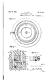
- Fig. 5 is a cross-sectional view taken on line 5--5 through the lower compartment of the refrigeration apparatus illustrated in Fig. 3
- Fig. 6 is a crosssectional view taken on line 6--5 of Fig.
- Fig. "l is a detailed cross-sectional view illustrating the arrangement of the intake and outlet ports in the driving apparatus
- Fig. 8 is a cross-sectional view through the exhaust port taken on line 8-4 of Fig. 7
- Fig. 9 is a view showing an air cooled machine constructed in accordance with my invention.
- the refrigeration apparatus comprises a unit designated by reference character I which may be located in any convenient place with'reference to a cabinet refrigerator 2.
- the refrigeration apparatus includes a driving mechanism and a compressing mechanism.
- the driving apparatus forms in itself. a compartment designated by reference character 3, while the compressing mechanism is disposed within a. portion of a condenser the armature 24 of the driving mechanism.
- the refrigeration apparatus may be either water cooled or air cooled but in Fig. 1-, I have shown the system through a connection I leading to a condenser shown more clearly in Fig. 3 by reference character I, the cooling. water passing from the condenser coils I and into connection I from which it is led to water jacket it which surrounds the compartment 3 formed by the driving apparatus.
- the waste water is delivered through connection ii.
- a pipe line I! conducts the refrigerant through the upper cover it of the compartment I formed by the driving mechanism. Liquid refrigerant is delivered by the refrigeration apparatus to a pipe line I! as will be more fully hereinafter described to the cooling system mounted within the refrigerator 2.
- liquid refrigerant is maintained at a predetermined level in tank II by a suitable float valve control mechanism l1 and issuppliedthroughapipeline ittotheevaporator cooling system or boiler ll. Heat is absorbed by the liquid refrigerant in the evaporator absorber or cooling tank is from food products or other contents within the chat of the refrigerator 1 and the refrigerant returned as a gas through pipe line I! to the refrigeration apparatus. All pipe line connections in the apparatus are well packed as indicated at 5a, 9a, 9b, Ila and lid to insure against leakage.
- the driving mechanism forms a part of the compartment inasmuch as the armature II and field II are subjected at all times to the gaseous refrigerant which may pass from the line I! through the space intermediate the armature and the field and through the space between the frame of the driving mechanism and the inside walls of the compartment as provided by the inwardly directed longitudinal extending ribs ll.
- the ribs 20 center the field of the motor within the compartment.
- the casting II is provided with a downwardly extending end bell ft.
- the extended casting as has the compressing mechanism mounted on the lower end thereof.
- the compressing mech anism may consist of one or more stages.
- I have; illustrated a compressor having a pair of'com-- pressor members Ill and Ii actuated by the extended shaft I! which is directly connectedwith shaft 32 carries eccentrics a and II dispom at degrees with respect to each other and mounted within each of the compressor members II; and ii in such manner that upon rotation of the extended shaft 32 an oscillatory or partially reciprocal motion is imparted to the compressor members Ill and ML
- and Ii are mounted within chambers II and [I spaced by the separator 31.
- the chamber .Hpressor members ll and ii. I that the ports in each ofthechambers II and II and separator plate 31 are aligned with the suction and discharge ports in the casting 29.
- the long extended casting which. comprises the bell It serves as means for securing an oily seal for separating the high and low prwsure areas of the refrigeration apparatus.
- the extended shaft 32 is :loumaled in bearings 39 and ll at opposite ends of the extended casting II. There is a slight clearance along the entire length of the shaft 32 between the walls of the extended bore II in the casting 29, which allows oil or lubricant to pass along the shaft 82 providing both automatic lubrication for the refrigeration apparatus and establishing an oil seal or an automatic stuffing box between the high and low pressure sidesof the system as will be more fully pointed out hereinafter.
- suction passage 44 leads to each oi. the compression chambers 35 and 38 for conducting gaseous refrigerant through the entrances and 41 shown more clearly in Fig. 'l to the compressor members III and ii.
- the compressor members 30 and ti by virtue of the motion imparted to them by rotation of the eccentrics 33 and 34 on the shaft 32 are moved upon members ll which rock in the side walls of the chambers ti and It as represented at Is.
- the members 48 comprise vanes havi g a portion which extends into a slot ll formed in the compressor members.
- and Si while free to oscillate and to have partial rotation or reciprocal motion do not rotate but serve to compress the gaseous refrigerant to a pressure corresponding to the temperature of liquefaction.
- charge pipe ll Surrounding the downwardly extending casting II and the compressing mechahim I provide a cylindrical screen IQ of relatively fine mesh which serves to separate oil or lubricant mm the refrigerant discharged at u. n will be noted that the refrigerant is'discharged at a point within the screen so that oil or lubricant exhausted by the compressor will be caught in a film on this screen where it trickles down the sides of the screen to the oil level 51 within the container I. In order to insure against the passage of oil or lubricant into the refrigeration system I place an additional screen 58 about the end of the gravity oil separator Bll which extends into the compartment 4.
- the inwardly projecting end of the gravity oil separator II is disposed at an angle OI with respect to the vertical in such manner that oil which is caught on the screen It tends to trickle oil and discharge into the oil reservoir in the lower part of the compartment 4.
- the screen It is suitably apertured about the base thereof as represented at If to permit the passage of oil freely along the bottom of the compartment 4. This arrangement enables me to provide automatic and self-lubrication for the refrigeration apparatus.
- the compartment I is under high pressure during the operation of the refrigeration apparatus.
- the motor housing is in a condition of low temperature.
- the compartment 4 is continuously cooled by means of the cooling coils I and the refrigerant liquefied.
- the refrigerant seeks a level approximately as represented at line H in Fig. 3.
- the refrigerant is forced under pressure through the gravity oil separator 60 wherein the tendency of any oil which may by chance have been carried along with the refrigerant is to return to the lower part of compartment 4.
- the refrigerant in the form of a liquid passes along the supply line ii to be usefully employed for the extraction of heat and is returned to the low pressure motor housing through pipe line I! for a repetition 'of the cycle.
- the apparatus of my invention may employ various kinds of refrigerants such as ethyl chloride, methyl chloride, sulphur dioxide, carbon dioxide and others. I have used with marked success, however, the refrigerant ethyl chloride and have obtained temperatures as low as degrees F. below zero.
- the driving motor is maintained at a desirably low temperature even under conditions of use over extended periods of time.
- the refrigerant should be returned through the suction line if, the refrigerant will be subjected to the mild temperature or heat of the motor armature 24 which will at once convert the liquid refrigerant into agas and facilitate the elimination of liquid refrigerant from the compressing mechanism.
- the expansion of the liquid refrigerant into a gas in direct contact with the motor windings further reduces the temperature at which the motor operates.
- the gaseous or liquefied refrigerant is conducted through the gravity oil separator 60 as heretofore explained.
- the refrigerant passes through an auxiliary coil ll before reaching the line ii.
- the purpose ofthe addition of the auxiliary coil is to more fully insure the liquefaction of the refrigerant by cooling.
- a refrigeration apparatus comprising in combination a compressing mechanism, a driving mechanism, a housing enclosing said driving mechanism and having a depending portion thereon supporting said compressing mechanism.
- said driving mechanism comprising a motor, an extended shaft on said motor Journaled in said depending portion and connected with said compressing mechanism, a condensing chamber surrounding said depending portion, means for cooling said condensing chamber, aport in said depending portion connecting said housing with said compressing mechanism, port means connecting said compressing mechanism with said condensing chamber, means Permitting gaseous refrigerant to flow through said driving mechanism in said housing, whereby said compressing mechanism operates to force said refrigerant, under pressure, into said condensing chamber for liquefying said refrigerant, and means for utilizing said refrigerant for absorbing heat.
- a refrigerating apparatus comprising in combination a casting having an extended vertical axis and formed with a bell at the upper end thereof and a downwardly depending extension, driving mechanism including a driven member and a stationary member with a gap therebetween forming a part of said bell, said driving mechanism having an extended shaft Journaled in said depending extension, a compressing mechanism supported on the lower extremity of said depending extension and driven by said shaft, a condensing chamber surrounding said depending portion, port means interconnecting said bell and said compressing mechanism, an inlet port in said bell whereby gaseous refrigerant may be conducted through the gap formed between said driven member and said stationary member of said driving mechanism and said ports to said compressing mechanism and delivered under pressure to said condensing chamber, and means for distributing liquefied refrigerant to a heat absorber for lowering the temperature of said heat absorber.
- a refrigeration apparatus the combination of a vertically extending casting, an enclosed driving mechanism carried by one end of said casting and sealed to atmosphere, said driving including a rotor and a stator separated by a gap, a compressing mechanism carried bythe other end of said casting, a shaft iournaled.
- a refrigeration apparatus comprising in combination supporting means including abell shaped housing, an integral portion downwardly depending from said housing, driving apparatus arranged in said housing and sealed to atmosphere, said driving apparatus including a rotor and a stator separated by a gap, compression mechanism carried by the extremity of said integral portion, a condenser surrounding said compression mechanism, intake and discharge ports positioned in-said integral portion said intake port connecting said housing and said compression mechanism, said discharge port leading to said condenser, and means for delivering gaseous refrigerant to said housing for e through the gap formed between said rotor and stator of said driving apparatus, said intake port, said compression mechanism and said discharge port, whereby refrigerant of high pressure may be secured.
- a refrigeration apparatus comprising in combination a sealed case including a condenser and a reservoir for liquid refrigerant, a casting closing the top of said case, an enclosed motor including a stator and rotor separated by a gap; said motor being mounted on said casting, an extended portion formed on said casting and entering said sealed case, a compression mechanism carried on the extremity of said casting, a shaft journaled in said extended portion and interconnecting said motor and said compression mechanism, whereby gaseous refrigerant may be passed between said stator and rotor and delivered under condensing pressure from pression mechanism.
- a compressing mechanism comprising an electric motor having rotor and stator elements, a casing enclosing said rotor and stator elements, said casing havsaid coming a laterally extending flange forming a cover for said condenser and sealing said condenser against leakage ofhigh pressure refrigerant therein, with a gap formed between the rotor and stator elements of said electric motor for conveying refrigerant to said compressing mechanism and simultaneously coolingsaid driving mechanism.
- a refrigeration apparatus comprising in com bination a compressing mechanism, a driving mechanism including a driven rotor and a stator separated therefrom by a gap, a shaft connecting said driving mechanism with said compressing mechanism, a condenser for refrigerant, a casing for said driving mechanism, said casing having an intermediate flange thereon forming a closure for one side of said condenser and sealing said condenser against leakage of high pressure refrigerant therein, lubricating means in said condenser and means whereby said high pressure refrigerant effects distribution of said lubricant. through a continuous cycle along said shaft between said driving and compressing mechanism in an upward direction, said refrigerant being directed through the gap between said rotor and stator elements in the course of its 1 tosaid condenser.
- a refrigeration apparatus including rotor and stator elements witir a gap formed therebetween, a compressing mechanism, a shaft interconnecting said driving mechanism with said compressing mechanism, a casing surrounding said shaft and enclodng said mechanism, said gap providing afor refrigerant through said driving mechanism to said compressing mechanism for continuously cooling said rotor and stator elements, a condenser containing lubricant in which said compressing mechanism is partially submerged, said compressing mechanism operating to discharge high pressure refrigerant into said condenser for creating high pressure therein, whereby said lubricant within said condenser is forced in a continuous cycle along said shaft in an upward direction through said driving mechanism and said compressing mechanism within said casing.
- a vertically arranged driving mechanism including rotor and stator elements separated by a gap, a compressing mechanism, a condenser surrounding said compressing mechanism, a rotary shaft, a casing surrounding said shaft and enclosing said mechanism, a reservoir for lubricant in said condenser, said driving mechanism being arranged for the conveyance of refrigerant through the gap between the rotor and stator elements of said mechanism to said compressing mechanism for discharge into said condenser for developing such pressure within said condenser that said lubricant is automatically forced through said mechanisms in a continuous cycle along said rotary shaft in an upward direction within said casing.
- a driving mechanism said driving mechanism including a rotor and a stator with a gap therebetween, a compressing mechanism actuated by the driving mechanism, an expansion system for refrigerant, a condenser, means defining with one end face of the driving mechanism a chamber for uniformly distributing expanded refrigerant circumferentially to one end of the driving mechanism before passage of said expanded refrigerant through the driving mechanism, and means for conveying refrigerant from the expansion system to said distributing chamber, said compressing mechanism having an inlet located to withdraw refrigerant from the opposite end of the driving mechanism and said driving mechanism having its rotor and stator directly interposed in the path of said refrigerant and arranged to provide a substantially longitudinal passageway for said refrigerant in its passage from said distributing chamber to said compressing mechanism inlet. whereby the driving mechanism is uniformly subjected to the cooling influence of an expanded refrigerant.
- a driving mechanism said driving mechanism including a rotor and a stator with a gap therebetween, a compressing mechanism actuated by said driving mechanism, means defining a casing for enclosing said driving mechanism and compressing mechanism, a plurality of radially positioned ribs formed on the interior walls of said enclosing means for positioning said stator element and for providing longitudinally-extending ports between the interior walls of said enclosing means and said stator element, an expansion system for refrigerant, a condenser, means defining with one endface of the driving mechanism a chamber for uniformly distributing expanded refrigerant circumferentially to said one end face of the driving mechanism before it enters the gap and ports, means for conveying refrigerant from the expansion system to the distributing chamber, said compressing mechanism having an inlet located to withdraw refrigerant from the opposite endof the driving mechanism and said driving mechanism having its rotor and stator directly interposed in the path of the refrigerant, so
- a driving mechanism said driving mechanism including a rotor and a stator with a gap therebetween, a compressing mechanism actuated by the driving mechanism, an expansion system for refrigerant, a condenser, means defining with one longitudinal end of the driving mechanism a chamber for uniformly distributing expanded refrigerant circumferentially to said end of the driving mechanism before passage of said expanded refrigerant through the driving mechanism and means for conveying refrigerant from the expansion system to said distributing chamber, said compressing mechanism being disposed and having an inlet at the opposite longitudinal end of the driving mechanism from said one longitudinal end thereof, and said driving mechanism having its rotor and stator directly interposed in the path of said refrigerant and arranged to provide a substantially longitudinal passageway for said refrigerant in its passage from said distributing chamber to said compressing mechanism inlet, whereby the driving mechanism is uniformly subjected to the cooling influence of an expanded
Description
Aug. 29, 1939. o. 1. PRICE REFRIGERATING APPARATUS Original Filed April 20, 1925 5 Sheets-Sheet l an-vm 1 for Oio/YZP], P1 726 Aug 29, 1939. 0-|, PRlCE Re. 21,189
REFRIGERATING APPARATUS Original Filed April 20, 1925 5 Sheets-Sheet 2 atbozvwq Aug. 29, 1939. o. 1. PRICE REFRIGERATING APPARATUS Original Filed April 20, '1925 v 5 Sheets-Sheet 5 gm/neuter g- 1939- o. l. PRICE REFRIGERATING' APPARATUS Original Filed April 20, 1925 5 Sheets-Sheet 4 gmwntc'a 0:60/726 Pf'l'a Ellie 14411 Reissued Aug. 29, 1939 H BEI'BIGBBATING APPARATUS Osborne 1. Price, Frederick, Md, llllllioi' to Westinghouse Electric d: Manufacturing Company, a corporation of Pennsylvania Original No. 1,807,871, dated June 2, 1931, Serial No. 24,599, April 20, 1925. Renewed October 28, 1930. Application for reissue June 15, 1939,
semi No. 279,380
12 Claims, (oi. ss-us) My invention relates broadly to refrigeration machines, and more particularly to a simplified construction of refrigeration apparatus having parts arranged for manufacturing inexpensively '6' on a quantity production basis.
One of the objects of my invention is to provide an apparatus for a refrigeration system which may be constructed in different capacities for household and domestic use, or for commerciai refrigeration systems of larger size, the general arrangement of parts for the various capacity machines varying for the installation of different capacity.
Another object of my invention is to provide a construction of refrigeration apparatus which is particularly adapted for domestic use by reason of its small physical dimensions, its constant operation over long periods of time at low maintenance expense, and its freedom from disagreeto able and obnoxious gases which heretofore have been a source of danger by the injury of food products in domestic systems.
Still another object of my invention is to provide a construction of refrigeration apparatus in as which all the moving parts are disposed within separate containers joined to form housings for the apparatus which may be conveniently mounted with respect to the usual ice box in the home and connected with cooling means within the ice box, for maintaining the foodstuffs at a constant cold temperature.
Another object of my invention is to provide a construction of refrigeration apparatus where the danger of leakage of the refrigerant is eliminated '36 by dispensing with conventional stuiling box connections or packing between the high and low pressure portions of the apparatus and providing continuous passages interconnecting the several portions in such manner that the passage of the refrigerant is constantly confined.
Another object of my invention is to provide a construction of refrigeration apparatus wherein the parts may be readily cast to form a rugged unit including a low pressure compartment which comprises the housing of the driving motor, and
a high pressure compartment in which is situated a pump or compressing mechanism driven by the said motor with the parts so arranged that leak- 0 age of the refrigerant between the different portions of the apparatus is substantially eliminated.
Still another object of my invention is to provide a construction of self-lubricating refrigeration apparatus whereby lubricant is forced through theapparatus in a continuous cycle during the running period, by the operation of the moving parts.
My invention further resides in the construction and assembly of a compressor and driver for refrigeration systems arranged to occupy a relatively small physical area and having high and low pressure compartments with a driving mechanism forming part of one of the compartments and a compressing mechanism in the other of the compartments, the compressing mechanism being arranged to deliver the refrigerant under pressure into the last mentioned compartment with means for cooling the refrigerant and delivering the same to the freezing system.
The construction of the apparatus of my invention will be more clearly understood from the specification hereinafter following by reference to the accompanying drawings, in which:
Figure 1 shows a part of the refrigeration system and the relative arrangement therein of the refrigeration apparatus of my invention; Fig. 2 is a fragmentary view illustrating that portion of the system which is disposed within the cooling chamber in proximity to.a storage chamber where products are to be maintained at a constant low temperature; Fig. 3 is a cross-sectional view taken through the rotary driving and compressing apparatus used in the refrigeration system; Fig. 4 is a cross-sectional view taken on line H of Fig. 3 through the rotary driving apparatus which forms the upper compartment of the refrigeration apparatus illustrated in Fig. 3; Fig. 5 is a cross-sectional view taken on line 5--5 through the lower compartment of the refrigeration apparatus illustrated in Fig. 3; Fig. 6 is a crosssectional view taken on line 6--5 of Fig. 3 through one of. the stages of the compressing mechanism employed in the refrigeration system; Fig. "l is a detailed cross-sectional view illustrating the arrangement of the intake and outlet ports in the driving apparatus; Fig. 8 is a cross-sectional view through the exhaust port taken on line 8-4 of Fig. 7; and Fig. 9 is a view showing an air cooled machine constructed in accordance with my invention. I
Referring to the drawings in detail the refrigeration apparatus comprises a unit designated by reference character I which may be located in any convenient place with'reference to a cabinet refrigerator 2. The refrigeration apparatus includes a driving mechanism and a compressing mechanism. The driving apparatus forms in itself. a compartment designated by reference character 3, while the compressing mechanism is disposed within a. portion of a condenser the armature 24 of the driving mechanism. The
compartment I. The refrigeration apparatus may be either water cooled or air cooled but in Fig. 1-, I have shown the system through a connection I leading to a condenser shown more clearly in Fig. 3 by reference character I, the cooling. water passing from the condenser coils I and into connection I from which it is led to water jacket it which surrounds the compartment 3 formed by the driving apparatus. The waste water is delivered through connection ii. A pipe line I! conducts the refrigerant through the upper cover it of the compartment I formed by the driving mechanism. Liquid refrigerant is delivered by the refrigeration apparatus to a pipe line I! as will be more fully hereinafter described to the cooling system mounted within the refrigerator 2. liquid refrigerant is maintained at a predetermined level in tank II by a suitable float valve control mechanism l1 and issuppliedthroughapipeline ittotheevaporator cooling system or boiler ll. Heat is absorbed by the liquid refrigerant in the evaporator absorber or cooling tank is from food products or other contents within the chat of the refrigerator 1 and the refrigerant returned as a gas through pipe line I! to the refrigeration apparatus. All pipe line connections in the apparatus are well packed as indicated at 5a, 9a, 9b, Ila and lid to insure against leakage.
Referring more particularly to Figure 3 of the drawings it will be observed that conventional stufllng boxes as heretofore required in refrigeration machines, have been eliminated in my design of refrigeration apparatus together with all the inherent disadvantages of such stufllng boxes. In eliminating the stufling boxes from the refrigeration apparatus I provide a casting 20 formed along a longitudinally extending vertical axis and having an upper bell which forms with the field and armature of the motor comprising-the driving mechanism, a gas tight compartment closed by the cover ll which'is suitably secured against the upper part of compartment 3 with a suitable gasket 23 between the annular flanges 2i and 2!. The driving mechanism forms a part of the compartment inasmuch as the armature II and field II are subjected at all times to the gaseous refrigerant which may pass from the line I! through the space intermediate the armature and the field and through the space between the frame of the driving mechanism and the inside walls of the compartment as provided by the inwardly directed longitudinal extending ribs ll. The ribs 20 center the field of the motor within the compartment. By this arrangement the gaseous refrigerant passes from the line I! in a downward direction through the annular gap 21 and the ports 2|.
The casting II is provided with a downwardly extending end bell ft. The extended casting as has the compressing mechanism mounted on the lower end thereof. The compressing mech anism may consist of one or more stages. I have; illustrated a compressor having a pair of'com-- pressor members Ill and Ii actuated by the extended shaft I! which is directly connectedwith shaft 32 carries eccentrics a and II dispom at degrees with respect to each other and mounted within each of the compressor members II; and ii in such manner that upon rotation of the extended shaft 32 an oscillatory or partially reciprocal motion is imparted to the compressor members Ill and ML The compressor members 3| and Ii are mounted within chambers II and [I spaced by the separator 31. The chamber .Hpressor members ll and ii. I that the ports in each ofthechambers II and II and separator plate 31 are aligned with the suction and discharge ports in the casting 29. The
l! is mounted directly adjacent the end of the bell 28 while the lower extremity of chamber It is closed by the end plate ll.
The long extended casting which. comprises the bell It serves as means for securing an oily seal for separating the high and low prwsure areas of the refrigeration apparatus. The extended shaft 32 is :loumaled in bearings 39 and ll at opposite ends of the extended casting II. There is a slight clearance along the entire length of the shaft 32 between the walls of the extended bore II in the casting 29, which allows oil or lubricant to pass along the shaft 82 providing both automatic lubrication for the refrigeration apparatus and establishing an oil seal or an automatic stuffing box between the high and low pressure sidesof the system as will be more fully pointed out hereinafter. The extended casting 2! is formed with a web portion 42 interconnecting the bore portion Ii in which shaft 32 is Journaled and a portion 43 in which is integrally cast the extended ports 44 and 45 being the suction from the motor, compartment and the discharge to the condenser compartment respecfrom the use of pipe lines and the packed joints in the suction and discharge passages which have heretofore been necessary in refrigeration apparatus. The suction passage 44 leads to each oi. the compression chambers 35 and 38 for conducting gaseous refrigerant through the entrances and 41 shown more clearly in Fig. 'l to the compressor members III and ii. The compressor members 30 and ti by virtue of the motion imparted to them by rotation of the eccentrics 33 and 34 on the shaft 32 are moved upon members ll which rock in the side walls of the chambers ti and It as represented at Is. As shown more clearly in Fig. 6 the members 48 comprise vanes havi g a portion which extends into a slot ll formed in the compressor members. The compressor members 3| and Si while free to oscillate and to have partial rotation or reciprocal motion do not rotate but serve to compress the gaseous refrigerant to a pressure corresponding to the temperature of liquefaction.
With my compressor .in operation I have successfully obtained and maintained pressures equal to 1'15 pounds gauge per square inch, equivalent to pounds absolute. pressure without reaching the limits of the compressing mechanism. While these pressures were being maintained I secured on the suction side a vacuum pressure corresponding approximately to 28 inches of mercury. in each of the chambers 35 and II I provide a spring pressed valve 5i interposedin eachofthe discharge ports I! and ll which operate to close thepassages I4 and II intermediate the compression strokes of the com- It will be observed refrigerant compressed to a pressure equivalent to' liquefaction is conducted along the port or passage II and discharged into the compartment I at a point adjacent the lower wall of the low pressure compartment-as represented by the dis.-
charge pipe ll. Surrounding the downwardly extending casting II and the compressing mechahim I provide a cylindrical screen IQ of relatively fine mesh which serves to separate oil or lubricant mm the refrigerant discharged at u. n will be noted that the refrigerant is'discharged at a point within the screen so that oil or lubricant exhausted by the compressor will be caught in a film on this screen where it trickles down the sides of the screen to the oil level 51 within the container I. In order to insure against the passage of oil or lubricant into the refrigeration system I place an additional screen 58 about the end of the gravity oil separator Bll which extends into the compartment 4. It will be observed that the inwardly projecting end of the gravity oil separator II is disposed at an angle OI with respect to the vertical in such manner that oil which is caught on the screen It tends to trickle oil and discharge into the oil reservoir in the lower part of the compartment 4. The screen It is suitably apertured about the base thereof as represented at If to permit the passage of oil freely along the bottom of the compartment 4. This arrangement enables me to provide automatic and self-lubrication for the refrigeration apparatus. The compartment I is under high pressure during the operation of the refrigeration apparatus. The motor housing is in a condition of low temperature. There is a normal tendency, therefore, for the pressure in compartment I to exert such effect upon lubricant in thelower part of compartment 4 that'the lubricant is forced upwardly through apertured member 63 and along the sleeve bearing ll progressively feeding into the low pressure motor housing. In this manner both bearings 39 and "are continuously lubricated. The lubricant which is forced into the low pressure motor housing returns along the suction passageway 4| and automatically lubricates the compressor mechanism in its entirety. As heretofore explained, oil which may be discharged by the compressing mechanism is not carried along with the refrigerant but is extracted therefrom by the screening means 56, I8 and the gravity oil separator Ill. The compartment 4 is continuously cooled by means of the cooling coils I and the refrigerant liquefied. The refrigerant seeks a level approximately as represented at line H in Fig. 3. The refrigerant is forced under pressure through the gravity oil separator 60 wherein the tendency of any oil which may by chance have been carried along with the refrigerant is to return to the lower part of compartment 4.
As heretofore explained the refrigerant in the form of a liquid passes along the supply line ii to be usefully employed for the extraction of heat and is returned to the low pressure motor housing through pipe line I! for a repetition 'of the cycle.
It is to be understood that the apparatus of my invention may employ various kinds of refrigerants such as ethyl chloride, methyl chloride, sulphur dioxide, carbon dioxide and others. I have used with marked success, however, the refrigerant ethyl chloride and have obtained temperatures as low as degrees F. below zero.
By my arrangement of refrigeration apparatus wherein the refrigerant actually passes through the moving parts of the driving mechanism, the driving motor is maintained at a desirably low temperature even under conditions of use over extended periods of time. In the event that liquid refrigerant should be returned through the suction line if, the refrigerant will be subjected to the mild temperature or heat of the motor armature 24 which will at once convert the liquid refrigerant into agas and facilitate the elimination of liquid refrigerant from the compressing mechanism. The expansion of the liquid refrigerant into a gas in direct contact with the motor windings further reduces the temperature at which the motor operates.
Connections for the driving motor'are brought out through leads 64 through any convenient part of the frame of the apparatus. I have shown terminal posts II provided for connecting the driving motor to the power supply system. While I have not illustrated any electrical control circuits for the driving mechanism I- desire that it be understood that any suitable method of automatic control and regulation of the motor circuit and also the water supply system may be employed. That is to say, the motor may be operatedand water supplied to the cooling system only during periods that temperature conditions actually demand the supply of refrigerant to the cooling or expansion tank ll.
I have illustrated the water cooled refrigeration system in the drawings, but it will be understood that my invention is equally applicable to an air cooled system as represented in Fig. 9. In this construction the upper bell I is ribbed as represented at 65. It will be observed that the fan projects for a-sumcient distance above the head H in order to provide for circulation of air over the casing. A suitable wire guard 12 is provided to prevent articles from being dropped into the path of the blades of the fan 10. The lower casing I encloses the depending casting 29. The discharge port 45 instead of exhausting at a point directly within the chamber 4 is connected to an external cooling coil 66 disposed about the outside walls of the chamber 4, from which coil it exhausts to the interior of the chamber 4 at a point represented at 81. The gaseous or liquefied refrigerant is conducted through the gravity oil separator 60 as heretofore explained. The refrigerant passes through an auxiliary coil ll before reaching the line ii. The purpose ofthe addition of the auxiliary coil is to more fully insure the liquefaction of the refrigerant by cooling.
It will be observed that the lubricant is forced in a' continuous cycle in a direction up the shaft 32, thence down the suction line and finally in spray with the refrigerant under pressure. As heretofore explained this method of lubrication insures long life to the apparatus. It will be observed that the compressor is normally submerged or partially submerged in the lubricant and due to the pressure in the condensing chamber there is a constant tendency for the lubricant to beforced upwardly around shaft 32. Furthermore due to the fact that high pressure exists about the compressing mechanism, there is no tendency for outward leakage to take place from the compressor. and gaskets therefore become unnecessary. The advantages of passing the refrigerant through the moving parts of the driving mechanism have already been pointed out. It will be understood that the windings for the motor are carefully protected to resist chemical action of the refrigerant. The insulation on the conductors forming the motor windings is impregnated with suitable insulation material and the windings may be soaked in Bakelite or other chemical and electrical resis'tant material. I have successively operated the motor over long periods in the presence of the refrigeration gases without detriment to the moving parts. The mounting of the motor on a bearing which is wholly below the driving parts enables the motor to be continuously lubricated What I claim and desire to secure by Letters Patents of the United States is as follows:
1. A refrigeration apparatus comprising in combination a compressing mechanism, a driving mechanism, a housing enclosing said driving mechanism and having a depending portion thereon supporting said compressing mechanism. said driving mechanism comprising a motor, an extended shaft on said motor Journaled in said depending portion and connected with said compressing mechanism, a condensing chamber surrounding said depending portion, means for cooling said condensing chamber, aport in said depending portion connecting said housing with said compressing mechanism, port means connecting said compressing mechanism with said condensing chamber, means Permitting gaseous refrigerant to flow through said driving mechanism in said housing, whereby said compressing mechanism operates to force said refrigerant, under pressure, into said condensing chamber for liquefying said refrigerant, and means for utilizing said refrigerant for absorbing heat.
2. A refrigerating apparatus comprising in combination a casting having an extended vertical axis and formed with a bell at the upper end thereof and a downwardly depending extension, driving mechanism including a driven member and a stationary member with a gap therebetween forming a part of said bell, said driving mechanism having an extended shaft Journaled in said depending extension, a compressing mechanism supported on the lower extremity of said depending extension and driven by said shaft, a condensing chamber surrounding said depending portion, port means interconnecting said bell and said compressing mechanism, an inlet port in said bell whereby gaseous refrigerant may be conducted through the gap formed between said driven member and said stationary member of said driving mechanism and said ports to said compressing mechanism and delivered under pressure to said condensing chamber, and means for distributing liquefied refrigerant to a heat absorber for lowering the temperature of said heat absorber.
3. In a refrigeration apparatus the combination of a vertically extending casting, an enclosed driving mechanism carried by one end of said casting and sealed to atmosphere, said driving including a rotor and a stator separated by a gap, a compressing mechanism carried bythe other end of said casting, a shaft iournaled. in said casting and connected with said driving mechanism for driving said compressing mechanism, condensing means surrounding said compressing mechanism, means for introducing gaseous refrigerant through the gap between said rotor and stator of said enclosed driving.meansforpassingsaidrefrigerant to said compressing mechanism carried by said casting, and means for delivering said refrigerant under pressure from one side of said casting and within said condensing means, whereby liquid refrigerant may be distributed to a heat absorber.
4. A refrigeration apparatus comprising in combination supporting means including abell shaped housing, an integral portion downwardly depending from said housing, driving apparatus arranged in said housing and sealed to atmosphere, said driving apparatus including a rotor and a stator separated by a gap, compression mechanism carried by the extremity of said integral portion, a condenser surrounding said compression mechanism, intake and discharge ports positioned in-said integral portion said intake port connecting said housing and said compression mechanism, said discharge port leading to said condenser, and means for delivering gaseous refrigerant to said housing for e through the gap formed between said rotor and stator of said driving apparatus, said intake port, said compression mechanism and said discharge port, whereby refrigerant of high pressure may be secured.
5. A refrigeration apparatus comprising in combination a sealed case including a condenser and a reservoir for liquid refrigerant, a casting closing the top of said case, an enclosed motor including a stator and rotor separated by a gap; said motor being mounted on said casting, an extended portion formed on said casting and entering said sealed case, a compression mechanism carried on the extremity of said casting, a shaft journaled in said extended portion and interconnecting said motor and said compression mechanism, whereby gaseous refrigerant may be passed between said stator and rotor and delivered under condensing pressure from pression mechanism.
6. In a refrigeration apparatus the combination of a compressing mechanism, a driving mechanism, and a condenser for refrigerant, said driving mechanism comprising an electric motor having rotor and stator elements, a casing enclosing said rotor and stator elements, said casing havsaid coming a laterally extending flange forming a cover for said condenser and sealing said condenser against leakage ofhigh pressure refrigerant therein, with a gap formed between the rotor and stator elements of said electric motor for conveying refrigerant to said compressing mechanism and simultaneously coolingsaid driving mechanism.
7. A refrigeration apparatus comprising in com bination a compressing mechanism, a driving mechanism including a driven rotor and a stator separated therefrom by a gap, a shaft connecting said driving mechanism with said compressing mechanism, a condenser for refrigerant, a casing for said driving mechanism, said casing having an intermediate flange thereon forming a closure for one side of said condenser and sealing said condenser against leakage of high pressure refrigerant therein, lubricating means in said condenser and means whereby said high pressure refrigerant effects distribution of said lubricant. through a continuous cycle along said shaft between said driving and compressing mechanism in an upward direction, said refrigerant being directed through the gap between said rotor and stator elements in the course of its 1 tosaid condenser.
8. In a refrigeration apparatus the combinationofaverticallyarrangeddriving u; m including rotor and stator elements witir a gap formed therebetween, a compressing mechanism, a shaft interconnecting said driving mechanism with said compressing mechanism, a casing surrounding said shaft and enclodng said mechanism, said gap providing afor refrigerant through said driving mechanism to said compressing mechanism for continuously cooling said rotor and stator elements, a condenser containing lubricant in which said compressing mechanism is partially submerged, said compressing mechanism operating to discharge high pressure refrigerant into said condenser for creating high pressure therein, whereby said lubricant within said condenser is forced in a continuous cycle along said shaft in an upward direction through said driving mechanism and said compressing mechanism within said casing.
9. In a refrigerating apparatus the combination of a vertically arranged driving mechanism including rotor and stator elements separated by a gap, a compressing mechanism, a condenser surrounding said compressing mechanism, a rotary shaft, a casing surrounding said shaft and enclosing said mechanism, a reservoir for lubricant in said condenser, said driving mechanism being arranged for the conveyance of refrigerant through the gap between the rotor and stator elements of said mechanism to said compressing mechanism for discharge into said condenser for developing such pressure within said condenser that said lubricant is automatically forced through said mechanisms in a continuous cycle along said rotary shaft in an upward direction within said casing.
10. In refrigeration apparatus, the combination of a driving mechanism, said driving mechanism including a rotor and a stator with a gap therebetween, a compressing mechanism actuated by the driving mechanism, an expansion system for refrigerant, a condenser, means defining with one end face of the driving mechanism a chamber for uniformly distributing expanded refrigerant circumferentially to one end of the driving mechanism before passage of said expanded refrigerant through the driving mechanism, and means for conveying refrigerant from the expansion system to said distributing chamber, said compressing mechanism having an inlet located to withdraw refrigerant from the opposite end of the driving mechanism and said driving mechanism having its rotor and stator directly interposed in the path of said refrigerant and arranged to provide a substantially longitudinal passageway for said refrigerant in its passage from said distributing chamber to said compressing mechanism inlet. whereby the driving mechanism is uniformly subjected to the cooling influence of an expanded refrigerant.
11. In refrigeration apparatus, the combination of a driving mechanism, said driving mechanism including a rotor and a stator with a gap therebetween, a compressing mechanism actuated by said driving mechanism, means defining a casing for enclosing said driving mechanism and compressing mechanism, a plurality of radially positioned ribs formed on the interior walls of said enclosing means for positioning said stator element and for providing longitudinally-extending ports between the interior walls of said enclosing means and said stator element, an expansion system for refrigerant, a condenser, means defining with one endface of the driving mechanism a chamber for uniformly distributing expanded refrigerant circumferentially to said one end face of the driving mechanism before it enters the gap and ports, means for conveying refrigerant from the expansion system to the distributing chamber, said compressing mechanism having an inlet located to withdraw refrigerant from the opposite endof the driving mechanism and said driving mechanism having its rotor and stator directly interposed in the path of the refrigerant, so that said gap and longitudinally-extending ports provide substantially longitudinal and annular passageways for said refrigerant in its passage from the distributing chamber to the compressing mechanism inlet, whereby the stator and the rotor are uniformly subjected to the cooling influence of an expanded refrigerant about their circumferences;
12. In refrigeration apparatus, the combination of a driving mechanism, said driving mechanism including a rotor and a stator with a gap therebetween, a compressing mechanism actuated by the driving mechanism, an expansion system for refrigerant, a condenser, means defining with one longitudinal end of the driving mechanism a chamber for uniformly distributing expanded refrigerant circumferentially to said end of the driving mechanism before passage of said expanded refrigerant through the driving mechanism and means for conveying refrigerant from the expansion system to said distributing chamber, said compressing mechanism being disposed and having an inlet at the opposite longitudinal end of the driving mechanism from said one longitudinal end thereof, and said driving mechanism having its rotor and stator directly interposed in the path of said refrigerant and arranged to provide a substantially longitudinal passageway for said refrigerant in its passage from said distributing chamber to said compressing mechanism inlet, whereby the driving mechanism is uniformly subjected to the cooling influence of an expanded
Publications (1)
| Publication Number | Publication Date |
|---|---|
| USRE21189E true USRE21189E (en) | 1939-08-29 |
Family
ID=2086731
Family Applications (1)
| Application Number | Title | Priority Date | Filing Date |
|---|---|---|---|
| US21189D Expired USRE21189E (en) | Refrigerating apparatus |
Country Status (1)
| Country | Link |
|---|---|
| US (1) | USRE21189E (en) |
Cited By (5)
| Publication number | Priority date | Publication date | Assignee | Title |
|---|---|---|---|---|
| US2594512A (en) * | 1949-05-06 | 1952-04-29 | Air Prod Inc | Liquid pumping system |
| US2937807A (en) * | 1956-12-26 | 1960-05-24 | Heraeus Gmbh W C | High vacuum pumps |
| US2940661A (en) * | 1957-01-14 | 1960-06-14 | Heraeus Gmbh W C | Vacuum pumps |
| US2950046A (en) * | 1956-01-28 | 1960-08-23 | Heraeus Gmbh W C | High vacuum pump |
| US3232523A (en) * | 1962-11-23 | 1966-02-01 | Borsig Ag | Rotary piston compressor with rotary pistons arranged eccentrically one within the other |
-
0
- US US21189D patent/USRE21189E/en not_active Expired
Cited By (5)
| Publication number | Priority date | Publication date | Assignee | Title |
|---|---|---|---|---|
| US2594512A (en) * | 1949-05-06 | 1952-04-29 | Air Prod Inc | Liquid pumping system |
| US2950046A (en) * | 1956-01-28 | 1960-08-23 | Heraeus Gmbh W C | High vacuum pump |
| US2937807A (en) * | 1956-12-26 | 1960-05-24 | Heraeus Gmbh W C | High vacuum pumps |
| US2940661A (en) * | 1957-01-14 | 1960-06-14 | Heraeus Gmbh W C | Vacuum pumps |
| US3232523A (en) * | 1962-11-23 | 1966-02-01 | Borsig Ag | Rotary piston compressor with rotary pistons arranged eccentrically one within the other |
Similar Documents
| Publication | Publication Date | Title |
|---|---|---|
| US2243466A (en) | Refrigerating apparatus | |
| US3866438A (en) | Motor cooling apparatus utilizing a refrigerant flow circuit | |
| US2134936A (en) | Motor compressor unit for refrigerating apparatus | |
| USRE21189E (en) | Refrigerating apparatus | |
| US2040507A (en) | Pump for refrigeration apparatus | |
| US2214086A (en) | Refrigerating apparatus | |
| US1945338A (en) | Pumping unit for refrigerating apparatus | |
| US1807871A (en) | Refrigerating apparaus | |
| US1890205A (en) | Refrigerating apparatus | |
| US2121049A (en) | Refrigeration apparatus | |
| US2517367A (en) | Gas compressor | |
| US2031080A (en) | Motor pump and condensing unit | |
| US1797287A (en) | Refrigerating machine | |
| US2738657A (en) | Relief valve for rotary compressor | |
| US1263633A (en) | Electric-driven refrigerating-machine. | |
| US1807872A (en) | Refrigeration apparatus | |
| US3389569A (en) | Method and apparatus for refrigeration machine lubrication | |
| US1934189A (en) | Inclosed motor pump unit | |
| US1867719A (en) | Motor operated machine unit | |
| US2983435A (en) | Lubricant fluid control apparatus for pumping systems | |
| US1719810A (en) | Refrigerating machine | |
| US2174233A (en) | Sealed motor compressor unit | |
| US2056646A (en) | Refrigerating apparatus | |
| US1925166A (en) | Compression unit for refrigerating systems | |
| US1932607A (en) | Refrigerating system |