USRE44806E1 - Electrical adapter for medical diagnostic instruments using LEDs as illumination sources - Google Patents
Electrical adapter for medical diagnostic instruments using LEDs as illumination sources Download PDFInfo
- Publication number
- USRE44806E1 USRE44806E1 US12/572,811 US57281109A USRE44806E US RE44806 E1 USRE44806 E1 US RE44806E1 US 57281109 A US57281109 A US 57281109A US RE44806 E USRE44806 E US RE44806E
- Authority
- US
- United States
- Prior art keywords
- led
- adapter
- recited
- instrument
- power supply
- Prior art date
- Legal status (The legal status is an assumption and is not a legal conclusion. Google has not performed a legal analysis and makes no representation as to the accuracy of the status listed.)
- Active, expires
Links
Images


Classifications
-
- A—HUMAN NECESSITIES
- A61—MEDICAL OR VETERINARY SCIENCE; HYGIENE
- A61B—DIAGNOSIS; SURGERY; IDENTIFICATION
- A61B1/00—Instruments for performing medical examinations of the interior of cavities or tubes of the body by visual or photographical inspection, e.g. endoscopes; Illuminating arrangements therefor
- A61B1/227—Instruments for performing medical examinations of the interior of cavities or tubes of the body by visual or photographical inspection, e.g. endoscopes; Illuminating arrangements therefor for ears, i.e. otoscopes
-
- Y—GENERAL TAGGING OF NEW TECHNOLOGICAL DEVELOPMENTS; GENERAL TAGGING OF CROSS-SECTIONAL TECHNOLOGIES SPANNING OVER SEVERAL SECTIONS OF THE IPC; TECHNICAL SUBJECTS COVERED BY FORMER USPC CROSS-REFERENCE ART COLLECTIONS [XRACs] AND DIGESTS
- Y10—TECHNICAL SUBJECTS COVERED BY FORMER USPC
- Y10S—TECHNICAL SUBJECTS COVERED BY FORMER USPC CROSS-REFERENCE ART COLLECTIONS [XRACs] AND DIGESTS
- Y10S323/00—Electricity: power supply or regulation systems
- Y10S323/911—Medical electronics
Definitions
- the following application generally relates to the field of illumination, and more particularly to an LED illumination system intended for use with hand held medical diagnostic instruments, such as those used in a physician's or health care provider's office, or other medical environments.
- otoscopes such as those from Heine Inc., Welch Allyn, Inc., and Keeler Instruments, among others, have long since utilized miniature incandescent lamps, such as halogen and xenon lamps, as illumination sources. These lamps are typically provided within the handle or the head of the instrument and utilize fiber optic bundles or other optical means to transmit the light from the miniature lamp to the tip opening of the diagnostic instrument, such as an ophthalmoscope, otoscope, or similar device.
- miniature incandescent lamps such as halogen and xenon lamps
- Power sources for these lamps are typically either wall mounted or are portable, in the form of batteries provided in the instrument handle and having a nominal voltage of approximately 2.5 or 3.5 volts. These voltages are convenient values, since they match both a stacked arrangement of two or three Nickel cadmium batteries and 3.5 volts in particular is favored since it is also the voltage of a single lithium ion cell. Examples of instruments having same are described, for example, in U.S. Pat. Nos. 4,012,686, 5,559,422, 5,177,424, and 5,542,904.
- LEDs light emitting diodes
- White versions of these LEDs such as those described, for example, in U.S. Pat. Nos. 6,069,440 and 5,998,925, among others, the entire contents of which are herein incorporated by reference, provide better illumination capability than predecessor LEDs and are therefore wished for a myriad of applications due to their longer life, resistance to shock and impact loads, cooler operating temperatures and alternative spectral content as compared with the afore mentioned miniature incandescent lamps.
- LEDs in general, such as color LEDs provide additional benefits such as spectral tuning, IR, spectrally specific illumination, and the like.
- an electrical adapter for use with a medical diagnostic instrument typically configured with an incandescent lamp as an illumination source and a power supply for powering said incandescent lamp, said adapter having means for permitting at least one LED to be used as the illumination source for said instrument while permitting said existing power supply to used therewith.
- the adapter preferably includes an AC to DC converter in order to compensate for variations in forward voltage of at least one white LED used as an illumination source and to effect polarity discrepancies.
- the AC to DC converter can consist of, for example, at least one diode bridge or a MOSFET switch.
- the adapter also preferably includes means for compensating LED specific differences such as current, voltage boost, regulation, and color sense, thereby permitting use of the diagnostic instrument having at least one white LED with already existing power supplies and/or battery charging apparatus.
- the LED electrical adapter can be disposed within the head of the diagnostic instrument so as to permit interchangeability of illumination devices; that is, in which one interchangeable instrument head can include a miniature incandescent lamp and another interchangeable head includes a least one white LED and an electrical adapter permitting the LED to be utilized with the remainder of the instrument whether the instrument includes a wall mounted power supply or batteries.
- the LED electrical adapter can be fitted in lieu of a conventional battery within the instrument handle.
- the adapter in fact, can be manufactured and sized so as to effectively replace a battery within the handle.
- an adapter for use with a medical diagnostic instrument, said instrument including a power supply, electrically configured for powering an incandescent bulb as an illumination source, said instrument including an instrument head, a hand-grippable handle and at least one LED disposed in said instrument as the illumination source of said instrument, said adapter including means for electrically interconnecting said power supply and said at least one LED for effectively energizing said at least one LED.
- a method for adapting a medical diagnostic instrument for use with at least one LED as an illumination source said instrument including a power supply typically only electrically configured for energizing an incandescent lamp as an illumination source, said method comprising the steps of:
- a method for adapting a existing medical diagnostic instrument so as to incorporate at least one LED as an illumination source said existing instrument including a power supply for energizing a miniature incandescent bulb as an illumination source, said instrument including an existing instrument head and a existing instrument handle wherein said existing instrument head and said existing instrument handle include mating interconnecting ends which interlock said instrument head and said handle in a mechanical interconnection while simultaneously maintaining an electrical interface between said incandescent lamp and said power supply, said method including the steps of:
- said adapter including means for electrically interconnecting at least one LED and said power supply as well as means for mechanically interconnecting said instrument head and said instrument handle;
- An advantage of the present invention is that the herein described electrical adapter permits a number of hand-held medical diagnostic instruments to be used with any previously existing power supplies or battery charging apparatus used therein without significant modification.
- Still another advantage of the present invention is that the herein described electrical adapter permits each of the advantages of LEDs to be brought to the diagnostic instrument. These advantages which include longer lamp life, longer battery life, reduced maintenance, and higher reliability without significantly impacting cost which heretofore could not easily be brought to the instrument without significant redesign of the electrical system.
- FIG. 1 is a partial side section view of the head of a prior art medical diagnostic instrument
- FIG. 2 is a partial side sectioned view of the medical diagnostic instrument of FIG. 1 , including a portable battery power source;
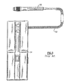
- FIG. 3 is a front view of another prior art medical instrument including a wall-mounted power supply
- FIG. 4 is a side perspective view of a prior art diagnostic instrument illustrating the interconnection between an instrument head and the instrument handle/power supply;
- FIG. 5 is an enlarged side perspective view of the instrument head/handle-power supply interconnection of FIG. 4 ;
- FIG. 6 is a partial side view of the interconnection between another prior art instrument head and instrument handle
- FIG. 7 is an unassembled view of the instrument of FIG. 6 ;
- FIG. 8 is a schematic block diagram of an LED electrical adapter made in accordance with the present invention.
- FIG. 9 is an electrical circuit diagram of an embodiment of the LED electrical adapter of FIG. 8 ;
- FIG. 10 is an electrical circuit diagram of a current compensation portion of the LED electrical adapter of FIG. 8 ;
- FIG. 11 is a side elevational view, partially in section, of a medical diagnostic instrument having an LED electrical adapter made in accordance with a preferred embodiment of the present invention
- FIG. 12 is a side elevational view, partially in section, of a medical diagnostic instrument having an LED electrical adapter made in accordance with another preferred embodiment of the present invention.
- FIGS. 12(a) and 12(b) are side elevational views of a diagnostic instrument head, partially in section, including means for detecting the illumination mode of the head in accordance with a preferred embodiment of the present invention
- FIG. 13 is a side elevational partial perspective view of a LED electrical adapter for a medical diagnostic instrument made in accordance with yet another preferred embodiment of the present invention.
- FIG. 14 is a side perspective view of the LED electrical adapter of FIG. 13 ;
- FIG. 15 is a side elevational view of a portion of the adapter of FIGS. 13 and 14 ;
- FIG. 16 is a circuit diagram of a microcontroller system for detecting the presence of an incandescent bulb or an LED.
- the following description relates in general to an LED electrical adapter that can be used in a hand-held medical diagnostic instrument, such as an ophthalmoscope, otoscope, vaginoscope, and the like, though the embodiments described herein detail a specific instrument, namely an otoscope.
- the diagnostic instrument 10 is a conventional otoscope, used for the examination of the outer ear, including the tympanic membrane.
- This instrument 10 generally includes a hollow instrument handle 14 and an instrument head 18 that is attached to the top of the handle.
- the instrument head 18 is hollow and includes a frustoconical tip portion 40 onto which a disposable speculum (not shown) is fitted in a conventional manner, such as a bayonet 44 .
- the speculum is sized for fitting a predetermined distance into the ear canal of a patient, the tip portion 40 having a distal tip opening 42 .
- An eyepiece 46 attached to the proximal end 48 of the instrument head 18 forms an optical path with the distal tip opening 42 through the hollow instrument head 18 to permit viewing of the medical target.
- a miniature incandescent lamp 22 such as a halogen or xenon lamp, is provided in a lamp housing 25 that is disposed in a base 27 of the instrument head 18 , the lamp being electrically connected through a contact 29 and a vertically extending pin 31 to a series of stacked Nickel cadmium batteries 26 that are retained in a bottom compartment of the instrument handle 14 for energizing the lamp 22 .
- the instrument handle 14 also contains a bottom or lower contact spring 33 .
- An adjustable voltage control 30 located on the exterior of the upper portion of the instrument handle 14 selectively adjusts the amount of illumination output provided by the miniature lamp 22 .
- a pair of prior art instruments 10 A, 10 B therefore each include a mechanical interface between the instrument head 18 A, 18 B and the upper end of the instrument handle 14 A, 14 B such that when the instrument head is attached to the handle that the above electrical connection is maintained between the lamp and the power supply for the instrument.
- each of the instruments employ a form of a bayonet connection.
- the base 27 A of the instrument head 18 A includes an interior set of slots (not shown) for engaging a circumferential set of ears 32 (only one being shown) provided on the exterior of the upper portion 28 A of the handle 14 A.
- FIGS. 6 and 7 A functionally similar instrument is shown in FIGS. 6 and 7 for an ophthalmoscope in which the base 27 B includes a set of ears 37 for engaging a corresponding set of slots located in the upper portion 28 B of the instrument handle 14 B to permit the electrical contact 39 to be placed into electrical contact with the power supply of the instrument to permit illumination of the lamp disposed within the base 27 B.
- a hand-held medical diagnostic instrument handle 50 can be tethered by means of a cord 52 directly to a wall transformer or similar power supply 54 , such as shown in FIG. 3 .
- a series of optical fibers 38 extend from the miniature incandescent lamp 22 through the base 27 of the instrument head 18 , to a bundle of light transmitting ends 36 or other optical means that are disposed at the distal tip opening 42 in order to provide illumination of the medical target (e.g., the tympanic membrane).
- a series of optical fibers 38 extend from the miniature incandescent lamp 22 through the base 27 of the instrument head 18 , to a bundle of light transmitting ends 36 or other optical means that are disposed at the distal tip opening 42 in order to provide illumination of the medical target (e.g., the tympanic membrane).
- One typical wall transformer is further described in U.S. Pat. No. 5,559,422, incorporated herein in its entirety.
- FIG. 8 there is shown a block diagram of an LED electrical adapter 60 made in accordance with a preferred embodiment of the present invention.
- This electrical adapter 60 includes a number of primary features that are required in order to permit already existing power supplies, such as those shown in FIGS. 1-7 , to be used in conjunction with at least one white LED package 64 that would be substituted for the miniature incandescent lamp 22 , FIG. 1 , in a medical diagnostic instrument.
- the mechanical and electrical design of the inventive adapter can assume a plurality of electrical, mechanical and electrical configurations covered in general by all or some features of the block diagram of FIG. 8 , permitting the adapter to be used in conjunction with literally any existing power supply that provides power to an incandescent lamp-equipped medical diagnostic instrument.
- the LED electrical adapter 60 includes a voltage conversion portion 84 and a compensation portion 100 .
- a voltage conversion portion 84 and a compensation portion 100 .
- the compensation portion is presumed to be a current compensation portion, although other characteristics such as voltage, light output and/or color compensation are similarly implemented.
- the voltage conversion portion 84 herein is an AC or DC converter which can be constructed, for example, as a simple diode bridge so as to provide proper selection of the forward voltage drop of at least one white LED package 64 .
- the voltage conversion portion 84 permits both AC and DC power supplies to utilized.
- any polarity mismatch between the LED package 64 and the previously utilized miniature incandescent lamp 22 would also be corrected using this converter portion.
- LEDs require unipolar DC current in order to illuminate.
- the current compensation portion 100 can include each of the following: a general current compensation means 104 for provided a limited maximum current, and a high/low stopper regulator 108 .
- a resistor or a PTC positive thermal coefficient e.g., thermistor
- this “solution” provides partial compensation to an “average” white LED in average conditions.
- this form of current compensation may not adequately compensate under low and high supply voltage conditions because the resulting differential voltage between the power source and the LED forward voltage will be directly translated into current difference when using a PTC or resistor as the compensating element. In some instances, the LED forward voltage will be higher than the source voltage and therefore no conduction will occur at all.
- a typical 3.5 volt battery power handle ranges between 3.0 volts and 4.2 volts and a typical white LED (such as, for example, a Lumileds Luxeon LXHL-MWIA) has a forward voltage of between about 2.55 volts and about 3.99 volts. These low voltage conditions would occur as the batteries within the instrument handle discharge, or with low line or power supplies that are set at the low end of their manufacturing tolerances.
- Regulating/limiting systems for current compensation can include for example, linear regulators, such as, for example, a National Semiconductor LM1117.
- a bimetallic switch can be applied which can be set to create a duty cycle which averages a corrected current in order to produce a stable consistent output as long as the voltage provided by the power source is sufficiently above the forward voltage of the LED.
- a circuit is herein described that controls the voltage to an LED which is used in lieu of a miniature incandescent bulb.
- the circuit can further be configured to control the light output of the LED or the color output of the LED by selecting the appropriate detector (photodiode with or without filter) and connecting the detector to the sense feed line.
- the voltage control circuit of FIG. 9 functions as follows:
- An oscillator (U 1 ) is assumed to be a voltage controlled oscillator having a base frequency and a duty cycle that is a function of the input voltage.
- PWM pulse width modulation
- this circuit does not rely on any particular such device.
- the voltage across a pair of resistors (R 2 ) and (R 3 ) would be zero, and the sense voltage would be zero.
- a comparator (U 2 ) powers up, the sense voltage (zero at start) will be compared with the reference (U 3 ) and a positive error signal will be generated. This error is fed to the oscillator (U 1 ) which increases its on time cycle, thereby driving transistor (Q 1 ) to turn on.
- the preceding causes current to flow through an inductor (L 1 ) and stores energy as an electromagnetic field.
- a diode (D 1 ) This feeding creates a voltage and drives current into the LED when the voltage becomes higher than the LED threshold (forward voltage) which is sensed via a pair of voltage dividers (R 2 ) and (R 3 ). If this voltage remains lower than the reference (U 3 ), the error comparator (U 2 ) continues to generate a positive error and the oscillator continues to increase its pulse width which increases the energy which is stored in (L 1 ), and consequently the output voltage into the LED.
- the error comparator (U 2 ) When the output and therefore the sense voltage becomes higher than that of the reference (U 3 ), the error comparator (U 2 ) generating a negative error signal which decreases the oscillator on time to reduce the output voltage. This process continues and maintains the output close to the reference voltage that is selected.
- the reference voltage is chosen to be the optimum setting for LED operation.
- this circuit represents a simplified current control, as represented in compensation block 100 , FIG. 8 .
- any other sensing means can be introduced such that the above circuit would respond to other changes such as light level, color, etc.
- FIG. 9 includes a means for adequate energy storage in L 1 , FIG. 9 , to bring the apparent source voltage to the LED above the forward voltage of the LED and then regulate the subsequent current which is drawn.
- the regulator can be replaced by a low resistance MOSFET.
- Including an oscillator to the design of the current compensation portion as in FIG. 9 would also permit dimming of the LED using either a duty cycle or a pulse width modulation technique. Since LEDs do not dim gradually and predictably with a decrease in voltage, use of the duty cycle would take advantage of the LEDs relatively fast “on/off” time to create “apparent” dimming for the user.
- the oscillator can be replaced with a bimetallic element. This substitution also provides the opportunity to modify the light output by rapidly pulsing the LED at a duty cycle which represents the modified intensity desired.
- FIGS. 11-15 a number of potential locations for the herein Described electrical LED adapter can be assumed, exemplary embodiments being herein described.
- a battery-powered diagnostic instrument 120 such as previously described in FIGS. 1 and 2 , that further includes an adaptor module 124 carrying the electrical circuitry of FIGS. 9 and/or 10 , the module being disposed between the instrument head 128 and the top of the handle 132 .
- the adapter 124 includes a housing 136 including a resident printed circuit board 140 and respective electrical contacts 144 , 148 provided at opposing ends of the housing.
- a white LED 152 such as described in U.S. Pat. No.
- 5,998,925 is disposed within a cavity 156 formed within the lower portion of the instrument head 128 wherein the LED includes at least one contact 160 that is placed in proximity with the upper facing contact 144 of the adapter 124 .
- the lower facing contact 148 of the adapter 124 is arranged in relation to the retained batteries 168 disposed within the handle 132 .
- a set of optics 172 are optionally disposed in relation to the LED die for coupling with the illumination output of the LED 152 .
- a similarly designed LED electrical adapter 176 can assume other locations relative to the medical diagnostic instrument.
- the adapter 176 is disposed within a cavity 180 formed within the interior of the instrument head 177 along with an LED 188 having contacts that engage a printed circuit board 190 having the circuitry previously described.
- the adapter 176 further includes a lower contact 194 that engages the batteries (not shown) provided in the handle (not shown).
- an LED electrical adapter includes a compact cartridge 200 that is sized so as to replace an existing battery typically retained within an instrument handle 204 .
- the adapter cartridge 200 is preferably defined in a cylindrical shape and is sized similarly to that of a contained battery to permit fitting into the instrument handle 204 in lieu thereof.
- This electrical cartridge includes a slot 208 that retains specific voltage conversion means in the form of a voltage conversion means 220 , having elements as defined above, the cartridge being disposed between one of the batteries 210 and the extending pin contact extending from the instrument head (not shown) as well as an extending negative contact strip 214 enabling a suitable electrical connection between the battery 210 and the LED (not shown).
- Each of the above assemblies can be retained in a housing (not shown for clarity) of convenient size.
- an optical system can be added or modified to improve color.
- a suitable filter and a collection lens can be placed at the light transmitting end of an LED having its top lens removed.
- the filter may also be part of this lens and the assembly may alternately be part of the LED or incorporated into part of the instrument head.
- a means for detecting and switching the drive electronics from an LED version to an incandescent lamp version of a diagnostic instrument is beneficial, since this switching ability allows the same instrument to take advantage of each illumination system.
- FIGS. 12(a) and 12(b) show alternative illumination sources as previously described.
- an incandescent lamp 228 is disposed in a diagnostic instrument head 232 , such as an otoscope head, the incandescent lamp having leads 236 , 240 extending to respective contact surfaces 244 , 248 .
- Contact surface 244 is located at the bottom of the lamp module 252 in a proximal end of the instrument head while contact surface 248 is located adjacent the lamp module 252 .
- a third contact surface 256 is established along the exterior of the instrument head 232 , this portion of the head being separated from contact surface 244 by an insulator 260 .
- the operation of the mode switch is based upon the combination of contact surfaces engaged.
- the incandescent lamp 228 is energized by supplying electrical energy from the handle or otherwise between contact surfaces 256 and 244 , each of which are in direct contact with the lamp module 252 .
- an LED module 266 is situated in the instrument head 232 wherein the LED 270 is energized by supplying electrical energy between contact surfaces 244 and 248 , each of which are in direct electrical contact with the LED module through respective electrical contacts 274 and 278 via electrical adapter 60 .
- the adapter can provide a means for different contacts for the LED and the incandescent lamp, such that simply inserting the desired illumination device automatically selects the proper drive circuitry/configuration.
- the mechanical contact geometry can be the same for both illumination devices, and the adapter electronics can detect the presence or lack of polarity whether the illumination is an LED (polarized) or an incandescent bulb (not polarized). The above objective can be accomplished, in a preferred embodiment, using a microcontroller system such as illustrated in FIG. 16 .
- a microcontroller U 1 turns on half H-bridges Q 1 / 2 and Q 3 / 4 sequentially and checks the resulting voltage at resistors R 1 and R 2 . If the resulting voltage is the same, this provides an indicator that the current flow is symmetric in both directions, indicating a non-polarized illumination device and therefore the device located at U 4 in this circuit would be determined to be an incandescent lamp. If the voltage is different between R 1 and R 2 , the device would be determined to be polarized, indicating that the device located at U 4 is an LED. In addition, the direction of polarity would also be known allowing the drive circuitry to be properly connected.
- microcontroller U 1 is presumed to include an analog to digital converter that is used to convert the analog voltage present at R 1 and R 2 to a digital reading. While there are several microcontrollers which have this feature, the analog to digital converter could be implemented separately if needed. Also, the drive circuitry and connection to U 4 is intentionally left out of this diagram for the sake of simplicity and to convey the essential concepts of the invention. However it should be obvious to one of sufficient skill in the field that it can be accomplished even as simply as adding additional H-bridge sections (not shown) under microcontroller control.
Abstract
Description
- Parts List for
FIGS. 1-16 - 10 medical diagnostic instrument
- 10A, 10B diagnostic instrument
- 14 instrument handle
- 14A, 14B instrument handle
- 18 instrument head
- 18A, 18B instrument head
- 22 miniature halogen lamp
- 25 lamp housing
- 26 batteries
- 27 base
- 27A, 27B base
- 28A, 28B upper end
- 29 contact
- 30 adjustable voltage control
- 31 pin
- 32 ears
- 33 contact spring
- 36 light transmitting ends
- 37 ears
- 38 optical fibers
- 39 contact pin
- 40 tip portion
- 42 distal tip opening
- 44 bayonet
- 46 eyepiece
- 48 proximal end
- 50 instrument handle
- 52 cord
- 54 wall transformer
- 60 electrical LED adapter
- 64 LED package
- 84 AC or DC converter
- 100 current compensation portion
- 120 instrument
- 124 adaptor module
- 128 instrument head
- 132 handle
- 136 housing
- 140 printed circuit board
- 144 contact
- 148 contact
- 152 LED
- 156 cavity
- 160 contact
- 168 batteries
- 172 optics
- 176 adapter
- 177 instrument head
- 180 cavity
- 188 LED
- 190 printed circuit board
- 194 lower contact
- 200 cartridge
- 204 handle
- 208 slot
- 210 batteries
- 214 negative contact strip
- 220 voltage conversion means
- 228 incandescent lamp
- 232 instrument head
- 236 lead
- 240 lead
- 244 contact surface
- 248 contact surface
- 252 lamp module
- 256 contact surface
- 260 insulator
- 266 LED module
- 270 LED
- 274 electrical contact
- 278 electrical contact
Claims (100)
Priority Applications (1)
| Application Number | Priority Date | Filing Date | Title |
|---|---|---|---|
| US12/572,811 USRE44806E1 (en) | 2003-03-20 | 2009-10-02 | Electrical adapter for medical diagnostic instruments using LEDs as illumination sources |
Applications Claiming Priority (2)
| Application Number | Priority Date | Filing Date | Title |
|---|---|---|---|
| US10/393,319 US7276025B2 (en) | 2003-03-20 | 2003-03-20 | Electrical adapter for medical diagnostic instruments using LEDs as illumination sources |
| US12/572,811 USRE44806E1 (en) | 2003-03-20 | 2009-10-02 | Electrical adapter for medical diagnostic instruments using LEDs as illumination sources |
Related Parent Applications (1)
| Application Number | Title | Priority Date | Filing Date |
|---|---|---|---|
| US10/393,319 Reissue US7276025B2 (en) | 2003-03-20 | 2003-03-20 | Electrical adapter for medical diagnostic instruments using LEDs as illumination sources |
Publications (1)
| Publication Number | Publication Date |
|---|---|
| USRE44806E1 true USRE44806E1 (en) | 2014-03-18 |
Family
ID=32988120
Family Applications (3)
| Application Number | Title | Priority Date | Filing Date |
|---|---|---|---|
| US10/393,319 Ceased US7276025B2 (en) | 2003-03-20 | 2003-03-20 | Electrical adapter for medical diagnostic instruments using LEDs as illumination sources |
| US11/804,136 Expired - Lifetime US7458934B2 (en) | 2003-03-20 | 2007-05-17 | Electrical adapter for medical diagnostic instruments using replaceable LEDs as illumination sources |
| US12/572,811 Active 2024-06-03 USRE44806E1 (en) | 2003-03-20 | 2009-10-02 | Electrical adapter for medical diagnostic instruments using LEDs as illumination sources |
Family Applications Before (2)
| Application Number | Title | Priority Date | Filing Date |
|---|---|---|---|
| US10/393,319 Ceased US7276025B2 (en) | 2003-03-20 | 2003-03-20 | Electrical adapter for medical diagnostic instruments using LEDs as illumination sources |
| US11/804,136 Expired - Lifetime US7458934B2 (en) | 2003-03-20 | 2007-05-17 | Electrical adapter for medical diagnostic instruments using replaceable LEDs as illumination sources |
Country Status (5)
| Country | Link |
|---|---|
| US (3) | US7276025B2 (en) |
| EP (1) | EP1608256B1 (en) |
| AU (1) | AU2004224408B2 (en) |
| CA (1) | CA2523820A1 (en) |
| WO (1) | WO2004084716A1 (en) |
Cited By (5)
| Publication number | Priority date | Publication date | Assignee | Title |
|---|---|---|---|---|
| US20140275790A1 (en) * | 2013-03-15 | 2014-09-18 | Welch Allyn, Inc. | Illumination device, system, and method of use |
| USD741531S1 (en) | 2012-10-17 | 2015-10-20 | Welch Allyn, Inc. | Illuminator for a medical device or the like |
| US9198560B2 (en) * | 2012-03-19 | 2015-12-01 | Welch Allyn, Inc. | Medical diagnostic instrument |
| USD753295S1 (en) | 2014-06-27 | 2016-04-05 | Welch Allyn, Inc. | Illuminator for a medical device or the like |
| USD759868S1 (en) | 2012-10-17 | 2016-06-21 | Welch Allyn, Inc. | Illuminator for a medical device or the like |
Families Citing this family (97)
| Publication number | Priority date | Publication date | Assignee | Title |
|---|---|---|---|---|
| JP2005506854A (en) * | 2001-03-14 | 2005-03-10 | ウェスタン シドニー エリア ヘルス サービス | Laryngoscope |
| US7276025B2 (en) | 2003-03-20 | 2007-10-02 | Welch Allyn, Inc. | Electrical adapter for medical diagnostic instruments using LEDs as illumination sources |
| US6836157B2 (en) * | 2003-05-09 | 2004-12-28 | Semtech Corporation | Method and apparatus for driving LEDs |
| DE20317671U1 (en) * | 2003-11-15 | 2004-02-12 | Kirchner, Regina | Medical diagnostic device |
| WO2005096678A1 (en) * | 2004-03-31 | 2005-10-13 | Pioneer Corporation | Illumination control circuit |
| US7425803B2 (en) * | 2004-08-31 | 2008-09-16 | Stmicroelectronics, Inc. | Method and circuit for driving a low voltage light emitting diode |
| US7780089B2 (en) | 2005-06-03 | 2010-08-24 | Hand Held Products, Inc. | Digital picture taking optical reader having hybrid monochrome and color image sensor array |
| US7611060B2 (en) | 2005-03-11 | 2009-11-03 | Hand Held Products, Inc. | System and method to automatically focus an image reader |
| US7568628B2 (en) | 2005-03-11 | 2009-08-04 | Hand Held Products, Inc. | Bar code reading device with global electronic shutter control |
| JP2009501551A (en) * | 2005-04-01 | 2009-01-22 | ウェルチ アレン インコーポレーテッド | Colposcope instrument |
| US8388523B2 (en) | 2005-04-01 | 2013-03-05 | Welch Allyn, Inc. | Medical diagnostic instrument having portable illuminator |
| US7770799B2 (en) | 2005-06-03 | 2010-08-10 | Hand Held Products, Inc. | Optical reader having reduced specular reflection read failures |
| EP1759653A1 (en) * | 2005-09-06 | 2007-03-07 | W & H Dentalwerk Bürmoos GmbH | Adaptor for a medical handpiece, medical handpiece and medical power unit |
| US7771350B2 (en) * | 2005-10-21 | 2010-08-10 | General Electric Company | Laryngoscope and laryngoscope handle apparatus including an LED and which may include an ergonomic handle |
| US7758203B2 (en) | 2006-04-03 | 2010-07-20 | Welch Allyn, Inc. | Power connections and interface for compact illuminator assembly |
| US8142352B2 (en) | 2006-04-03 | 2012-03-27 | Welch Allyn, Inc. | Vaginal speculum assembly having portable illuminator |
| US20070255108A1 (en) * | 2006-05-01 | 2007-11-01 | Schmitz James D | Water resistant l.e.d. pocket otoscope |
| SI22525A (en) * | 2007-05-05 | 2008-12-31 | OPTOTEK@d.o.o. | Module with white light diode for simple replacement of the bulb module inside a permanent slot light |
| DE102007023316A1 (en) * | 2007-05-16 | 2008-12-18 | Frank Abert | Equipment for examining object, particularly organism, by ray of light, has light source from which ray of light proceeds, which with energy source is connected, where light source is assigned with exchangeable light beam channel |
| US8576036B2 (en) | 2010-12-10 | 2013-11-05 | Correlated Magnetics Research, Llc | System and method for affecting flux of multi-pole magnetic structures |
| US8760251B2 (en) | 2010-09-27 | 2014-06-24 | Correlated Magnetics Research, Llc | System and method for producing stacked field emission structures |
| US8179219B2 (en) | 2008-04-04 | 2012-05-15 | Correlated Magnetics Research, Llc | Field emission system and method |
| US8368495B2 (en) | 2008-04-04 | 2013-02-05 | Correlated Magnetics Research LLC | System and method for defining magnetic structures |
| US8760250B2 (en) | 2009-06-02 | 2014-06-24 | Correlated Magnetics Rsearch, LLC. | System and method for energy generation |
| US8816805B2 (en) | 2008-04-04 | 2014-08-26 | Correlated Magnetics Research, Llc. | Magnetic structure production |
| US9202616B2 (en) | 2009-06-02 | 2015-12-01 | Correlated Magnetics Research, Llc | Intelligent magnetic system |
| US8279032B1 (en) | 2011-03-24 | 2012-10-02 | Correlated Magnetics Research, Llc. | System for detachment of correlated magnetic structures |
| US9105380B2 (en) | 2008-04-04 | 2015-08-11 | Correlated Magnetics Research, Llc. | Magnetic attachment system |
| US7800471B2 (en) | 2008-04-04 | 2010-09-21 | Cedar Ridge Research, Llc | Field emission system and method |
| US8174347B2 (en) | 2010-07-12 | 2012-05-08 | Correlated Magnetics Research, Llc | Multilevel correlated magnetic system and method for using the same |
| US8779879B2 (en) | 2008-04-04 | 2014-07-15 | Correlated Magnetics Research LLC | System and method for positioning a multi-pole magnetic structure |
| US9371923B2 (en) | 2008-04-04 | 2016-06-21 | Correlated Magnetics Research, Llc | Magnetic valve assembly |
| US20100091244A1 (en) * | 2008-07-19 | 2010-04-15 | Volk Donald A | Real image forming eye examination lens utilizing two reflecting surfaces with non-mirrored central viewing area |
| DE102008052545A1 (en) * | 2008-10-21 | 2010-04-22 | Sew-Eurodrive Gmbh & Co. Kg | Arrangement with braking resistor |
| US8937521B2 (en) | 2012-12-10 | 2015-01-20 | Correlated Magnetics Research, Llc. | System for concentrating magnetic flux of a multi-pole magnetic structure |
| US8917154B2 (en) | 2012-12-10 | 2014-12-23 | Correlated Magnetics Research, Llc. | System for concentrating magnetic flux |
| TWM366991U (en) * | 2009-04-06 | 2009-10-21 | Tsu-I Hsia | Structure improvement of hand-held intravenous injection imaging transilluminator |
| WO2010132517A2 (en) * | 2009-05-12 | 2010-11-18 | David Gershaw | Led retrofit for miniature bulbs |
| US7956546B2 (en) * | 2009-05-15 | 2011-06-07 | Bridgelux, Inc. | Modular LED light bulb |
| US9257219B2 (en) | 2012-08-06 | 2016-02-09 | Correlated Magnetics Research, Llc. | System and method for magnetization |
| US8704626B2 (en) | 2010-05-10 | 2014-04-22 | Correlated Magnetics Research, Llc | System and method for moving an object |
| US9275783B2 (en) | 2012-10-15 | 2016-03-01 | Correlated Magnetics Research, Llc. | System and method for demagnetization of a magnetic structure region |
| US9404776B2 (en) | 2009-06-02 | 2016-08-02 | Correlated Magnetics Research, Llc. | System and method for tailoring polarity transitions of magnetic structures |
| US7862173B1 (en) | 2009-07-29 | 2011-01-04 | VistaMed, LLC | Digital imaging ophthalmoscope |
| US20110054263A1 (en) * | 2009-08-28 | 2011-03-03 | Jim-Son Chou | Replaceable LED illumination assembly for medical instruments |
| US8344543B2 (en) * | 2009-09-02 | 2013-01-01 | Mphase Technologies, Inc. | Modular device |
| US9711268B2 (en) | 2009-09-22 | 2017-07-18 | Correlated Magnetics Research, Llc | System and method for tailoring magnetic forces |
| DE102009052380B4 (en) * | 2009-11-09 | 2013-10-10 | Heine Optotechnik Gmbh & Co Kg | Lighting device, for medical diagnostic equipment |
| CA2779965A1 (en) * | 2009-12-17 | 2011-06-23 | Alcon Research, Ltd. | Photonic lattice leds for ophthalmic illumination |
| US20110148304A1 (en) * | 2009-12-22 | 2011-06-23 | Artsyukhovich Alexander N | Thermoelectric cooling for increased brightness in a white light l.e.d. illuminator |
| JP5162058B2 (en) * | 2009-12-23 | 2013-03-13 | 株式会社モリタ製作所 | Light emitting diode lighting parts |
| US9314374B2 (en) * | 2010-03-19 | 2016-04-19 | Alcon Research, Ltd. | Stroboscopic ophthalmic illuminator |
| US8786210B2 (en) | 2010-06-30 | 2014-07-22 | Welch Allyn, Inc. | Drive circuit for light emitting diode |
| US8459844B2 (en) | 2010-07-01 | 2013-06-11 | Welch Allyn, Inc. | Replacement light assembly |
| WO2012019194A2 (en) * | 2010-08-06 | 2012-02-09 | Ballard Jay A | Portable power module assembly |
| US8573801B2 (en) | 2010-08-30 | 2013-11-05 | Alcon Research, Ltd. | LED illuminator |
| US8638016B2 (en) | 2010-09-17 | 2014-01-28 | Correlated Magnetics Research, Llc | Electromagnetic structure having a core element that extends magnetic coupling around opposing surfaces of a circular magnetic structure |
| US9307897B2 (en) | 2010-09-28 | 2016-04-12 | Obp Corporation | Disposable speculum having lateral stabilizing mechanism |
| US9913577B2 (en) | 2010-09-28 | 2018-03-13 | Obp Medical Corporation | Speculum |
| EP2635174B1 (en) * | 2010-11-04 | 2019-07-03 | The Cleveland Clinic Foundation | Device for determining the presence of middle ear fluid |
| US8432088B2 (en) | 2011-01-03 | 2013-04-30 | Crs Electronics | Permanent conversion adapter for lighting fixtures |
| US8702437B2 (en) * | 2011-03-24 | 2014-04-22 | Correlated Magnetics Research, Llc | Electrical adapter system |
| US10008817B2 (en) * | 2011-03-24 | 2018-06-26 | Correlated Magnetics Research, Llc | Electrical adapter system |
| US9330825B2 (en) | 2011-04-12 | 2016-05-03 | Mohammad Sarai | Magnetic configurations |
| DE102011077724A1 (en) * | 2011-06-17 | 2012-12-20 | Siemens Aktiengesellschaft | Local shim coil within a local coil, as local BO homogenization in an MRI |
| US8963380B2 (en) | 2011-07-11 | 2015-02-24 | Correlated Magnetics Research LLC. | System and method for power generation system |
| US9219403B2 (en) | 2011-09-06 | 2015-12-22 | Correlated Magnetics Research, Llc | Magnetic shear force transfer device |
| US8848973B2 (en) | 2011-09-22 | 2014-09-30 | Correlated Magnetics Research LLC | System and method for authenticating an optical pattern |
| US8629926B2 (en) | 2011-11-04 | 2014-01-14 | Honeywell International, Inc. | Imaging apparatus comprising image sensor array having shared global shutter circuitry |
| US8992042B2 (en) | 2011-11-14 | 2015-03-31 | Halma Holdings, Inc. | Illumination devices using natural light LEDs |
| EP2820659A4 (en) | 2012-02-28 | 2016-04-13 | Correlated Magnetics Res Llc | System for detaching a magnetic structure from a ferromagnetic material |
| US9080911B2 (en) * | 2012-07-26 | 2015-07-14 | Illinois Tool Works Inc. | Boost converter for tracking input voltages |
| US9245677B2 (en) | 2012-08-06 | 2016-01-26 | Correlated Magnetics Research, Llc. | System for concentrating and controlling magnetic flux of a multi-pole magnetic structure |
| DE102012223691A1 (en) * | 2012-12-19 | 2014-06-26 | Heine Optotechnik Gmbh & Co Kg | Otoscope with disposable ear funnel |
| US9298281B2 (en) | 2012-12-27 | 2016-03-29 | Correlated Magnetics Research, Llc. | Magnetic vector sensor positioning and communications system |
| US9791129B2 (en) | 2013-08-27 | 2017-10-17 | Lightforce Australia Pty Ltd. | Hybrid light assembly |
| US9532706B2 (en) | 2014-08-07 | 2017-01-03 | Welch Allyn, Inc. | Vaginal speculum with illuminator |
| US10420538B2 (en) | 2015-02-05 | 2019-09-24 | Obp Medical Corporation | Illuminated surgical retractor |
| US9867602B2 (en) | 2015-02-05 | 2018-01-16 | Obp Medical Corporation | Illuminated surgical retractor |
| DE102015108217B3 (en) * | 2015-05-26 | 2016-09-22 | Heine Optotechnik Gmbh & Co Kg | Technique for adjusting the brightness of LED lamps |
| US10881387B2 (en) | 2015-06-03 | 2021-01-05 | Obp Medical Corporation | Retractor |
| CN108348229A (en) | 2015-06-03 | 2018-07-31 | Obp医学公司 | Retractor |
| US10939899B2 (en) | 2015-06-03 | 2021-03-09 | Obp Medical Corporation | End cap assembly for retractor and other medical devices |
| US10722621B2 (en) | 2016-07-11 | 2020-07-28 | Obp Medical Corporation | Illuminated suction device |
| US11172560B2 (en) | 2016-08-25 | 2021-11-09 | Alcon Inc. | Ophthalmic illumination system with controlled chromaticity |
| US10687793B2 (en) | 2017-07-18 | 2020-06-23 | Obp Medical Corporation | Minimally invasive no touch (MINT) procedure for harvesting the great saphenous vein (GSV) and venous hydrodissector and retractor for use during the MINT procedure |
| US10278572B1 (en) | 2017-10-19 | 2019-05-07 | Obp Medical Corporation | Speculum |
| CN111629644A (en) * | 2018-01-16 | 2020-09-04 | 伟伦公司 | Body evaluation apparatus |
| US11147441B2 (en) | 2018-01-16 | 2021-10-19 | Welch Allyn, Inc. | Physical assessment device |
| US10799229B2 (en) | 2018-02-20 | 2020-10-13 | Obp Medical Corporation | Illuminated medical devices |
| US10512519B2 (en) | 2018-02-20 | 2019-12-24 | Obp Medical Corporation | Illuminated medical devices |
| USD911521S1 (en) | 2019-02-19 | 2021-02-23 | Obp Medical Corporation | Handle for medical devices including surgical retractors |
| USD904607S1 (en) | 2019-05-07 | 2020-12-08 | Obp Medical Corporation | Nasal retractor |
| US10959609B1 (en) | 2020-01-31 | 2021-03-30 | Obp Medical Corporation | Illuminated suction device |
| US10966702B1 (en) | 2020-02-25 | 2021-04-06 | Obp Medical Corporation | Illuminated dual-blade retractor |
| US20220330803A1 (en) * | 2021-04-19 | 2022-10-20 | Welch Allyn, Inc. | Physical assessment device |
| US20220330793A1 (en) * | 2021-04-19 | 2022-10-20 | Welch Allyn, Inc. | Visually linear and discrete dimming for ophthalmoscopes and otoscopes and other medical examination or diagnostic instruments |
Citations (70)
| Publication number | Priority date | Publication date | Assignee | Title |
|---|---|---|---|---|
| US1828777A (en) | 1927-07-21 | 1931-10-27 | Julius H Leventhal | Ophthalmic test chart apparatus |
| US2027663A (en) | 1933-10-20 | 1936-01-14 | William N Allyn | Ophthalmoscope |
| GB1244529A (en) | 1968-09-13 | 1971-09-02 | American Optical Corp | Improvements in or relating to ophthalmoscopes |
| GB1372646A (en) | 1972-10-25 | 1974-11-06 | Holley J E F | Electric hand lamp devices such as hand torches and opthalmoscopes |
| US4012686A (en) * | 1971-03-18 | 1977-03-15 | Optotechnik, Gmbh | Power supply for illuminated instrument |
| US4211955A (en) * | 1978-03-02 | 1980-07-08 | Ray Stephen W | Solid state lamp |
| US4234910A (en) | 1978-03-20 | 1980-11-18 | Price Linda D | Head-supported illumination device |
| US4464608A (en) | 1982-09-13 | 1984-08-07 | Warner Lambert Technologies, Inc. | Circuit for controlling optical apparatus such as an ophthalmoscope |
| US4514476A (en) | 1982-04-08 | 1985-04-30 | Fitzgerald James L | Instrument for indirect ophthalmoscopy and electrical energy producing means therefor |
| US4527552A (en) | 1981-03-25 | 1985-07-09 | Olympus Optical Co., Ltd. | Endoscope apparatus |
| US4643546A (en) | 1984-07-09 | 1987-02-17 | Welch Allyn, Inc. | Ophthalmoscope with automatic lens shifting mechanism |
| US4699482A (en) | 1982-06-23 | 1987-10-13 | Utsugi Optical Laboratory Inc. | Opthalmoscopic system |
| US4710002A (en) | 1984-02-24 | 1987-12-01 | Eye Research Institute Of Retina Foundation | Magnifying ophthalmoscope |
| US4727289A (en) * | 1985-07-22 | 1988-02-23 | Stanley Electric Co., Ltd. | LED lamp |
| US4834528A (en) | 1986-08-15 | 1989-05-30 | Cornell Research Foundation, Inc. | Infrared photoretinoscope |
| WO1989008475A1 (en) | 1988-03-08 | 1989-09-21 | Brainard George C | Portable light unit for stimulating neuroendocrine system |
| US5144495A (en) | 1987-12-03 | 1992-09-01 | Compugrade, Inc | Systems for illuminating and evaluating surfaces |
| US5144190A (en) | 1990-02-22 | 1992-09-01 | Welch Allyn, Inc. | Light source having desired color temperature and chromaticity |
| US5177424A (en) * | 1991-09-20 | 1993-01-05 | Welch Allyn, Inc. | Instrument handle for use with interchangeable batteries |
| US5419312A (en) | 1993-04-20 | 1995-05-30 | Wildflower Communications, Inc. | Multi-function endoscope apparatus |
| US5430509A (en) | 1993-03-16 | 1995-07-04 | Kowa Company Ltd. | Scanning laser ophthalmoscope |
| US5450144A (en) | 1992-09-25 | 1995-09-12 | Optiko Scientific Ltd. | Ophthalmologic examination and/or treatment apparatus including illuminator and magnifier assembly |
| US5500698A (en) | 1984-11-09 | 1996-03-19 | Sims; Clinton N. | Optical instruments such as retinoscopes which may incorporate multiple lens assemblies and methods of calibrating such instruments |
| US5512966A (en) | 1993-06-24 | 1996-04-30 | Orbtek, Inc. | Ophthalmic pachymeter and method of making ophthalmic determinations |
| US5542904A (en) * | 1993-08-30 | 1996-08-06 | Heine Optotechnik Gmbh & Co. Kg | Handgrip for an electro-optical diagnostic apparatus set |
| US5559422A (en) * | 1994-07-01 | 1996-09-24 | Welch Allyn, Inc. | Wall transformer |
| US5568208A (en) | 1994-03-08 | 1996-10-22 | Van De Velde; Frans J. | Modified scanning laser opthalmoscope for psychophysical applications |
| US5568209A (en) | 1995-04-17 | 1996-10-22 | Priester; William B. | Automated pocket-sized near vision tester |
| US5614966A (en) | 1994-10-26 | 1997-03-25 | Kabushiki Kaisha Topcon | Ophthalmologic instrument |
| GB2310051A (en) | 1996-02-06 | 1997-08-13 | Bertil Damato | Aligning the condensing lens and eyepiece of a binocular indirect ophthalmoscope |
| US5734459A (en) | 1996-03-11 | 1998-03-31 | National Science Council | Anomaloscope which can generate different illuminances for test |
| WO1998049931A1 (en) | 1997-05-02 | 1998-11-12 | The General Hospital Corporation | Scanning opthalmoscope with spatial light modulators |
| US5838421A (en) | 1997-04-03 | 1998-11-17 | Pedack; Henry | Binocular direct opthalmoscope |
| US5841509A (en) | 1996-07-29 | 1998-11-24 | Harooni; Mark | Electro-optic binocular indirect ophthalmoscope |
| US5861939A (en) | 1997-10-16 | 1999-01-19 | Odyssey Optical Systems, Llc | Portable fundus viewing system for an undilated eye |
| US5886770A (en) | 1993-09-22 | 1999-03-23 | University Court Of The University Of Glasgow | Device for use in the examination of the visual field of a subject |
| US5887965A (en) | 1996-10-15 | 1999-03-30 | Escalon Medical Corp. | Cool white light source |
| US5919130A (en) | 1995-03-14 | 1999-07-06 | Welch Allyn, Inc. | Video otoscope |
| FR2773701A1 (en) | 1998-01-21 | 1999-07-23 | Plexus | Opthalmoscope for detection of healthy areas of the retina and determination of their visual acuteness |
| US5998925A (en) * | 1996-07-29 | 1999-12-07 | Nichia Kagaku Kogyo Kabushiki Kaisha | Light emitting device having a nitride compound semiconductor and a phosphor containing a garnet fluorescent material |
| US6106457A (en) * | 1997-04-04 | 2000-08-22 | Welch Allyn, Inc. | Compact imaging instrument system |
| US6130520A (en) * | 1998-03-13 | 2000-10-10 | Welch Allyn, Inc. | Diagnostic instrument system |
| US6142629A (en) | 1998-08-30 | 2000-11-07 | Applied Spectral Imaging Ltd. | Spectral imaging using illumination of preselected spectral content |
| US6158863A (en) | 1999-10-21 | 2000-12-12 | Scott I. Afran | Pediatric retinoscope |
| US6211626B1 (en) * | 1997-08-26 | 2001-04-03 | Color Kinetics, Incorporated | Illumination components |
| WO2001060241A1 (en) | 2000-02-15 | 2001-08-23 | Ian Marshall | Ophthalmoscope with multiple interchangeable groups of optical components |
| US6305818B1 (en) | 1998-03-19 | 2001-10-23 | Ppt Vision, Inc. | Method and apparatus for L.E.D. illumination |
| US6318887B1 (en) | 1998-08-21 | 2001-11-20 | Fuji Photo Optical Co., Ltd. | Battery-powered light source arrangement for endoscope |
| US6361167B1 (en) | 2000-06-13 | 2002-03-26 | Massie Research Laboratories, Inc. | Digital eye camera |
| US20020038075A1 (en) | 1998-11-25 | 2002-03-28 | Jory Tsai | Medical inspection device |
| US6368270B1 (en) | 1998-08-26 | 2002-04-09 | Asahi Kogaku Kogyo Kabushiki Kaisha | Lighting apparatus for endoscope and method of using an endoscopic system provided with the lighting apparatus |
| DE20119187U1 (en) | 2001-11-27 | 2002-04-18 | Witte & Sutor Gmbh | otoscope |
| US6406437B1 (en) | 2000-10-11 | 2002-06-18 | Yeda Research And Development Co. Ltd. | Method and apparatus for efficient high-resolution visual field mapping |
| US6439715B2 (en) | 2000-06-09 | 2002-08-27 | Rainer Burckhardt | Magnifying glass with illumination means for use in medicine and an illumination means |
| US6447119B1 (en) | 1996-08-12 | 2002-09-10 | Visionrx, Inc. | Apparatus for visualizing the eye's tear film |
| US6459919B1 (en) | 1997-08-26 | 2002-10-01 | Color Kinetics, Incorporated | Precision illumination methods and systems |
| US6520640B1 (en) | 1998-07-23 | 2003-02-18 | Talia Technology Ltd. | Acquiring, analyzing and imaging three-dimensional retinal data |
| US6547394B2 (en) * | 1998-10-20 | 2003-04-15 | Victor J. Doherty | Hand-held ophthalmic illuminator |
| US6550917B1 (en) | 2000-02-11 | 2003-04-22 | Wavefront Sciences, Inc. | Dynamic range extension techniques for a wavefront sensor including use in ophthalmic measurement |
| US6595643B2 (en) | 2001-06-05 | 2003-07-22 | Adaptive Optics Associates,.Inc. | Ophthalmic imaging instrument that measures and compensates for phase aberrations in reflections derived from light produced by an imaging light source |
| US6611320B1 (en) | 1999-09-08 | 2003-08-26 | Optoq Ab | Method and apparatus |
| US6637882B1 (en) | 1998-11-24 | 2003-10-28 | Welch Allyn, Inc. | Eye viewing device for retinal viewing through undilated pupil |
| US20040127771A1 (en) | 2002-12-27 | 2004-07-01 | Heine Optotechnik Gmbh & Co. Kg | Diagnostic instrument |
| US6766042B2 (en) | 2001-04-26 | 2004-07-20 | Memphis Eye & Contact Associates | System to automatically detect eye corneal striae |
| US20040252278A1 (en) | 2001-06-29 | 2004-12-16 | Williams William James | Light source for diagnostic iInstruments |
| US6893258B1 (en) * | 2002-06-11 | 2005-05-17 | Cms-Dental Aps | Dental material curing apparatus |
| US7276025B2 (en) | 2003-03-20 | 2007-10-02 | Welch Allyn, Inc. | Electrical adapter for medical diagnostic instruments using LEDs as illumination sources |
| US7435252B2 (en) * | 2003-10-15 | 2008-10-14 | Valam Corporation | Control of microorganisms in the sino-nasal tract |
| US7772786B2 (en) | 1999-12-02 | 2010-08-10 | Olympus Corporation | Battery-powered light source device for endoscope |
| US8157728B2 (en) * | 2005-04-01 | 2012-04-17 | Welch Allyn, Inc. | Vaginal speculum |
Family Cites Families (8)
| Publication number | Priority date | Publication date | Assignee | Title |
|---|---|---|---|---|
| US3614434A (en) | 1968-07-17 | 1971-10-19 | Lofstrom James E | Automatic agitating and sample device |
| US4311484A (en) | 1980-04-09 | 1982-01-19 | Cortex Research Corporation | Specimen sampling apparatus |
| US4399362A (en) | 1981-02-27 | 1983-08-16 | Instrumentation Laboratory Inc. | Liquid handling apparatus |
| EP0465691A1 (en) * | 1990-07-09 | 1992-01-15 | Hewlett-Packard GmbH | Apparatus for processing liquids |
| JP2564628Y2 (en) | 1991-08-01 | 1998-03-09 | 東亞医用電子株式会社 | Foam detection device in reagent sorting device |
| JP3049615B2 (en) | 1992-06-08 | 2000-06-05 | ベーリング ダイアグノスティックス,インコーポレーテッド | Liquid dispensing system |
| US5724142A (en) | 1996-03-29 | 1998-03-03 | Dade International Inc. | Method and apparatus for measuring and controlling the volume of a liquid segment in a tube |
| US6186944B1 (en) * | 1998-11-25 | 2001-02-13 | Jory Tsai | Medical inspection device |
-
2003
- 2003-03-20 US US10/393,319 patent/US7276025B2/en not_active Ceased
-
2004
- 2004-03-15 AU AU2004224408A patent/AU2004224408B2/en not_active Ceased
- 2004-03-15 CA CA002523820A patent/CA2523820A1/en not_active Abandoned
- 2004-03-15 EP EP04757772A patent/EP1608256B1/en not_active Expired - Fee Related
- 2004-03-15 WO PCT/US2004/008174 patent/WO2004084716A1/en active Application Filing
-
2007
- 2007-05-17 US US11/804,136 patent/US7458934B2/en not_active Expired - Lifetime
-
2009
- 2009-10-02 US US12/572,811 patent/USRE44806E1/en active Active
Patent Citations (75)
| Publication number | Priority date | Publication date | Assignee | Title |
|---|---|---|---|---|
| US1828777A (en) | 1927-07-21 | 1931-10-27 | Julius H Leventhal | Ophthalmic test chart apparatus |
| US2027663A (en) | 1933-10-20 | 1936-01-14 | William N Allyn | Ophthalmoscope |
| GB1244529A (en) | 1968-09-13 | 1971-09-02 | American Optical Corp | Improvements in or relating to ophthalmoscopes |
| US4012686A (en) * | 1971-03-18 | 1977-03-15 | Optotechnik, Gmbh | Power supply for illuminated instrument |
| GB1372646A (en) | 1972-10-25 | 1974-11-06 | Holley J E F | Electric hand lamp devices such as hand torches and opthalmoscopes |
| US4211955A (en) * | 1978-03-02 | 1980-07-08 | Ray Stephen W | Solid state lamp |
| US4234910A (en) | 1978-03-20 | 1980-11-18 | Price Linda D | Head-supported illumination device |
| US4527552A (en) | 1981-03-25 | 1985-07-09 | Olympus Optical Co., Ltd. | Endoscope apparatus |
| US4514476A (en) | 1982-04-08 | 1985-04-30 | Fitzgerald James L | Instrument for indirect ophthalmoscopy and electrical energy producing means therefor |
| US4699482A (en) | 1982-06-23 | 1987-10-13 | Utsugi Optical Laboratory Inc. | Opthalmoscopic system |
| US4464608A (en) | 1982-09-13 | 1984-08-07 | Warner Lambert Technologies, Inc. | Circuit for controlling optical apparatus such as an ophthalmoscope |
| US4710002A (en) | 1984-02-24 | 1987-12-01 | Eye Research Institute Of Retina Foundation | Magnifying ophthalmoscope |
| US4643546A (en) | 1984-07-09 | 1987-02-17 | Welch Allyn, Inc. | Ophthalmoscope with automatic lens shifting mechanism |
| US5500698A (en) | 1984-11-09 | 1996-03-19 | Sims; Clinton N. | Optical instruments such as retinoscopes which may incorporate multiple lens assemblies and methods of calibrating such instruments |
| US4727289A (en) * | 1985-07-22 | 1988-02-23 | Stanley Electric Co., Ltd. | LED lamp |
| US4834528A (en) | 1986-08-15 | 1989-05-30 | Cornell Research Foundation, Inc. | Infrared photoretinoscope |
| US5144495A (en) | 1987-12-03 | 1992-09-01 | Compugrade, Inc | Systems for illuminating and evaluating surfaces |
| WO1989008475A1 (en) | 1988-03-08 | 1989-09-21 | Brainard George C | Portable light unit for stimulating neuroendocrine system |
| US5144190A (en) | 1990-02-22 | 1992-09-01 | Welch Allyn, Inc. | Light source having desired color temperature and chromaticity |
| US5177424A (en) * | 1991-09-20 | 1993-01-05 | Welch Allyn, Inc. | Instrument handle for use with interchangeable batteries |
| US5450144A (en) | 1992-09-25 | 1995-09-12 | Optiko Scientific Ltd. | Ophthalmologic examination and/or treatment apparatus including illuminator and magnifier assembly |
| US5430509A (en) | 1993-03-16 | 1995-07-04 | Kowa Company Ltd. | Scanning laser ophthalmoscope |
| US5419312A (en) | 1993-04-20 | 1995-05-30 | Wildflower Communications, Inc. | Multi-function endoscope apparatus |
| US5512966A (en) | 1993-06-24 | 1996-04-30 | Orbtek, Inc. | Ophthalmic pachymeter and method of making ophthalmic determinations |
| US5542904A (en) * | 1993-08-30 | 1996-08-06 | Heine Optotechnik Gmbh & Co. Kg | Handgrip for an electro-optical diagnostic apparatus set |
| US5886770A (en) | 1993-09-22 | 1999-03-23 | University Court Of The University Of Glasgow | Device for use in the examination of the visual field of a subject |
| US5568208A (en) | 1994-03-08 | 1996-10-22 | Van De Velde; Frans J. | Modified scanning laser opthalmoscope for psychophysical applications |
| US5559422A (en) * | 1994-07-01 | 1996-09-24 | Welch Allyn, Inc. | Wall transformer |
| US5614966A (en) | 1994-10-26 | 1997-03-25 | Kabushiki Kaisha Topcon | Ophthalmologic instrument |
| US5919130A (en) | 1995-03-14 | 1999-07-06 | Welch Allyn, Inc. | Video otoscope |
| US5568209A (en) | 1995-04-17 | 1996-10-22 | Priester; William B. | Automated pocket-sized near vision tester |
| GB2310051A (en) | 1996-02-06 | 1997-08-13 | Bertil Damato | Aligning the condensing lens and eyepiece of a binocular indirect ophthalmoscope |
| US5734459A (en) | 1996-03-11 | 1998-03-31 | National Science Council | Anomaloscope which can generate different illuminances for test |
| US5998925A (en) * | 1996-07-29 | 1999-12-07 | Nichia Kagaku Kogyo Kabushiki Kaisha | Light emitting device having a nitride compound semiconductor and a phosphor containing a garnet fluorescent material |
| US5841509A (en) | 1996-07-29 | 1998-11-24 | Harooni; Mark | Electro-optic binocular indirect ophthalmoscope |
| US6069440A (en) * | 1996-07-29 | 2000-05-30 | Nichia Kagaku Kogyo Kabushiki Kaisha | Light emitting device having a nitride compound semiconductor and a phosphor containing a garnet fluorescent material |
| US6447119B1 (en) | 1996-08-12 | 2002-09-10 | Visionrx, Inc. | Apparatus for visualizing the eye's tear film |
| US5887965A (en) | 1996-10-15 | 1999-03-30 | Escalon Medical Corp. | Cool white light source |
| US5838421A (en) | 1997-04-03 | 1998-11-17 | Pedack; Henry | Binocular direct opthalmoscope |
| US6106457A (en) * | 1997-04-04 | 2000-08-22 | Welch Allyn, Inc. | Compact imaging instrument system |
| US6003993A (en) | 1997-05-02 | 1999-12-21 | The General Hospital Corp. | Scanning ophthalmoscope with spatial light modulators |
| WO1998049931A1 (en) | 1997-05-02 | 1998-11-12 | The General Hospital Corporation | Scanning opthalmoscope with spatial light modulators |
| US6340868B1 (en) | 1997-08-26 | 2002-01-22 | Color Kinetics Incorporated | Illumination components |
| US6459919B1 (en) | 1997-08-26 | 2002-10-01 | Color Kinetics, Incorporated | Precision illumination methods and systems |
| US6211626B1 (en) * | 1997-08-26 | 2001-04-03 | Color Kinetics, Incorporated | Illumination components |
| US5861939A (en) | 1997-10-16 | 1999-01-19 | Odyssey Optical Systems, Llc | Portable fundus viewing system for an undilated eye |
| FR2773701A1 (en) | 1998-01-21 | 1999-07-23 | Plexus | Opthalmoscope for detection of healthy areas of the retina and determination of their visual acuteness |
| US6130520A (en) * | 1998-03-13 | 2000-10-10 | Welch Allyn, Inc. | Diagnostic instrument system |
| US6305818B1 (en) | 1998-03-19 | 2001-10-23 | Ppt Vision, Inc. | Method and apparatus for L.E.D. illumination |
| US6520640B1 (en) | 1998-07-23 | 2003-02-18 | Talia Technology Ltd. | Acquiring, analyzing and imaging three-dimensional retinal data |
| US6318887B1 (en) | 1998-08-21 | 2001-11-20 | Fuji Photo Optical Co., Ltd. | Battery-powered light source arrangement for endoscope |
| US6368270B1 (en) | 1998-08-26 | 2002-04-09 | Asahi Kogaku Kogyo Kabushiki Kaisha | Lighting apparatus for endoscope and method of using an endoscopic system provided with the lighting apparatus |
| US6142629A (en) | 1998-08-30 | 2000-11-07 | Applied Spectral Imaging Ltd. | Spectral imaging using illumination of preselected spectral content |
| US6547394B2 (en) * | 1998-10-20 | 2003-04-15 | Victor J. Doherty | Hand-held ophthalmic illuminator |
| US6637882B1 (en) | 1998-11-24 | 2003-10-28 | Welch Allyn, Inc. | Eye viewing device for retinal viewing through undilated pupil |
| US20020038075A1 (en) | 1998-11-25 | 2002-03-28 | Jory Tsai | Medical inspection device |
| US6611320B1 (en) | 1999-09-08 | 2003-08-26 | Optoq Ab | Method and apparatus |
| US6158863A (en) | 1999-10-21 | 2000-12-12 | Scott I. Afran | Pediatric retinoscope |
| US7772786B2 (en) | 1999-12-02 | 2010-08-10 | Olympus Corporation | Battery-powered light source device for endoscope |
| US6550917B1 (en) | 2000-02-11 | 2003-04-22 | Wavefront Sciences, Inc. | Dynamic range extension techniques for a wavefront sensor including use in ophthalmic measurement |
| WO2001060241A1 (en) | 2000-02-15 | 2001-08-23 | Ian Marshall | Ophthalmoscope with multiple interchangeable groups of optical components |
| US6439715B2 (en) | 2000-06-09 | 2002-08-27 | Rainer Burckhardt | Magnifying glass with illumination means for use in medicine and an illumination means |
| US6361167B1 (en) | 2000-06-13 | 2002-03-26 | Massie Research Laboratories, Inc. | Digital eye camera |
| US6406437B1 (en) | 2000-10-11 | 2002-06-18 | Yeda Research And Development Co. Ltd. | Method and apparatus for efficient high-resolution visual field mapping |
| US6766042B2 (en) | 2001-04-26 | 2004-07-20 | Memphis Eye & Contact Associates | System to automatically detect eye corneal striae |
| US6609794B2 (en) | 2001-06-05 | 2003-08-26 | Adaptive Optics Associates, Inc. | Method of treating the human eye with a wavefront sensor-based ophthalmic instrument |
| US6595643B2 (en) | 2001-06-05 | 2003-07-22 | Adaptive Optics Associates,.Inc. | Ophthalmic imaging instrument that measures and compensates for phase aberrations in reflections derived from light produced by an imaging light source |
| US20040252278A1 (en) | 2001-06-29 | 2004-12-16 | Williams William James | Light source for diagnostic iInstruments |
| DE20119187U1 (en) | 2001-11-27 | 2002-04-18 | Witte & Sutor Gmbh | otoscope |
| US6893258B1 (en) * | 2002-06-11 | 2005-05-17 | Cms-Dental Aps | Dental material curing apparatus |
| US20040127771A1 (en) | 2002-12-27 | 2004-07-01 | Heine Optotechnik Gmbh & Co. Kg | Diagnostic instrument |
| US7276025B2 (en) | 2003-03-20 | 2007-10-02 | Welch Allyn, Inc. | Electrical adapter for medical diagnostic instruments using LEDs as illumination sources |
| US7458934B2 (en) | 2003-03-20 | 2008-12-02 | Welch Allyn, Inc. | Electrical adapter for medical diagnostic instruments using replaceable LEDs as illumination sources |
| US7435252B2 (en) * | 2003-10-15 | 2008-10-14 | Valam Corporation | Control of microorganisms in the sino-nasal tract |
| US8157728B2 (en) * | 2005-04-01 | 2012-04-17 | Welch Allyn, Inc. | Vaginal speculum |
Non-Patent Citations (13)
| Title |
|---|
| Blair, Frank W.: Activities of the Chihuahua Deer-Mouse in Relation to Light Intensity; Journal of Wildlife Management; vol. 7; No. 1; Jan. 1943; pp. 92-97. |
| Colvard, M: Abstract of-Preoperative Measurement of Scotopic Pupil Dilation Using an Office Pupillometer; Center for Ophthalmic Surgery; Journal of Cataract and Refractive Surgery; 1998; vol. 24, No. 12; pp. 1594-1597. |
| Colvard, M: Abstract of—Preoperative Measurement of Scotopic Pupil Dilation Using an Office Pupillometer; Center for Ophthalmic Surgery; Journal of Cataract and Refractive Surgery; 1998; vol. 24, No. 12; pp. 1594-1597. |
| Dreher, Andreas W.: Field Portable Digital Ophthalmoscope/Fundus Camera-Final Report Nov. 6, 1996-May 5, 1997; Jun. 1997; published by Laser Diagnostic Technologies, Inc.; 25 pgs. |
| Dreher, Andreas W.: Field Portable Digital Ophthalmoscope/Fundus Camera—Final Report Nov. 6, 1996-May 5, 1997; Jun. 1997; published by Laser Diagnostic Technologies, Inc.; 25 pgs. |
| Ferree, C.E. et al.: Intensity of Light in Relation to the Examination of the Eye; The British Journal of Ophthalmology; 1936; pp. 331-346. |
| Heimel, J. et al.: SNOM/STM Using a Tetrahedral Tip and a Sensitive Current-to-Voltage Converter; Journal of Microscopy, vol. 202, Pt. I; Apr. 2001; pp. 53-59. |
| Kondo et al.: Recording Multifocal Electroretinograms With Fundus Monitoring; vol. 38 No. 5; Apr. 1997; published by Investigative Ophthalmology & Visual Science; pp. 1049-1052. |
| Neurosurgery: A Manual and Atlas of Medical Ophthalmoscopy; vol. 36(5), May 1995, Copyright © by the Library of Congress of Neurological Surgeons, pp. 1052-1056. |
| Schaeffel et al.: Lower-field myopia and astigmatism in amphibians and chickens; Josa A, vol. 11, Issue 2, Feb. 1994; pp. 487-495. |
| Talbot, S.A. et al.: A Multibeam Ophthalmoscope for the Study of Retinal Physiology; Journal of the Optical Society of America; vol. 42, No. 12; Dec. 1952; pp. 931-936. |
| Welch Allyn: Diagnostic Instruments (Product literature/brochure); 1984, SL 1540; 27 pgs. |
| Welch Allyn: Electrically Illuminated Diagnostic Instruments, Mar. 15, 1966; 17 pgs. |
Cited By (6)
| Publication number | Priority date | Publication date | Assignee | Title |
|---|---|---|---|---|
| US9198560B2 (en) * | 2012-03-19 | 2015-12-01 | Welch Allyn, Inc. | Medical diagnostic instrument |
| USD741531S1 (en) | 2012-10-17 | 2015-10-20 | Welch Allyn, Inc. | Illuminator for a medical device or the like |
| USD759868S1 (en) | 2012-10-17 | 2016-06-21 | Welch Allyn, Inc. | Illuminator for a medical device or the like |
| US20140275790A1 (en) * | 2013-03-15 | 2014-09-18 | Welch Allyn, Inc. | Illumination device, system, and method of use |
| US9314149B2 (en) * | 2013-03-15 | 2016-04-19 | Welch Allyn, Inc. | Illumination device, system, and method of use |
| USD753295S1 (en) | 2014-06-27 | 2016-04-05 | Welch Allyn, Inc. | Illuminator for a medical device or the like |
Also Published As
| Publication number | Publication date |
|---|---|
| AU2004224408B2 (en) | 2008-10-09 |
| WO2004084716A1 (en) | 2004-10-07 |
| US20040183482A1 (en) | 2004-09-23 |
| US7276025B2 (en) | 2007-10-02 |
| US20070219417A1 (en) | 2007-09-20 |
| AU2004224408A1 (en) | 2004-10-07 |
| EP1608256B1 (en) | 2012-06-27 |
| EP1608256A1 (en) | 2005-12-28 |
| US7458934B2 (en) | 2008-12-02 |
| CA2523820A1 (en) | 2004-10-07 |
Similar Documents
| Publication | Publication Date | Title |
|---|---|---|
| USRE44806E1 (en) | Electrical adapter for medical diagnostic instruments using LEDs as illumination sources | |
| US9987110B2 (en) | Dental light device | |
| US20190357764A1 (en) | Vaginal speculum apparatus | |
| EP1492441B1 (en) | Apparatus and method for powering portable battery operated light sources | |
| US20070247867A1 (en) | Portable LED Light Source for an Endoscope or Boroscope | |
| EP2416730B1 (en) | Dental light device | |
| WO2001028407A1 (en) | Hand-held, portable camera with adaptable lens system | |
| WO2006131770A2 (en) | Multipurpose light source | |
| WO2004084715A1 (en) | Illumination system for medical diagnostic instrument | |
| EP2815719B1 (en) | Dental light curing device | |
| US20220330793A1 (en) | Visually linear and discrete dimming for ophthalmoscopes and otoscopes and other medical examination or diagnostic instruments | |
| CN111629644A (en) | Body evaluation apparatus | |
| US7533992B2 (en) | Light source for diagnostic instruments | |
| EP4079213A1 (en) | Physical assessment device | |
| JP4027588B2 (en) | Endoscope light source device | |
| US11406252B2 (en) | Portable and sterilizable light source | |
| JP2008149049A (en) | Light source driving unit for portable endoscope | |
| US20090027492A1 (en) | Electronic endoscope device | |
| CN217852888U (en) | Body evaluation device with coordinated LED drive circuitry for image capture | |
| JP2001169536A (en) | Battery driven lighting source for endoscope | |
| JP2001157666A (en) | Battery type light source device for endoscope | |
| AU2002256819A1 (en) | A new light source for diagnostic instruments | |
| JP2011146301A (en) | Light source device | |
| ITMI982511A1 (en) | DENTAL HANDPIECES FOR THE POLYMERIZATION OF PHOTO-HARDENING ORESINE COMPOUNDS |
Legal Events
| Date | Code | Title | Description |
|---|---|---|---|
| CC | Certificate of correction | ||
| FPAY | Fee payment |
Year of fee payment: 8 |
|
| AS | Assignment |
Owner name: JPMORGAN CHASE BANK, N.A., AS COLLATERAL AGENT, ILLINOIS Free format text: SECURITY INTEREST;ASSIGNORS:ALLEN MEDICAL SYSTEMS, INC.;HILL-ROM SERVICES, INC.;ASPEN SURGICAL PRODUCTS, INC.;AND OTHERS;REEL/FRAME:036582/0123 Effective date: 20150908 Owner name: JPMORGAN CHASE BANK, N.A., AS COLLATERAL AGENT, IL Free format text: SECURITY INTEREST;ASSIGNORS:ALLEN MEDICAL SYSTEMS, INC.;HILL-ROM SERVICES, INC.;ASPEN SURGICAL PRODUCTS, INC.;AND OTHERS;REEL/FRAME:036582/0123 Effective date: 20150908 |
|
| AS | Assignment |
Owner name: JPMORGAN CHASE BANK, N.A., AS COLLATERAL AGENT, ILLINOIS Free format text: SECURITY AGREEMENT;ASSIGNORS:HILL-ROM SERVICES, INC.;ASPEN SURGICAL PRODUCTS, INC.;ALLEN MEDICAL SYSTEMS, INC.;AND OTHERS;REEL/FRAME:040145/0445 Effective date: 20160921 Owner name: JPMORGAN CHASE BANK, N.A., AS COLLATERAL AGENT, IL Free format text: SECURITY AGREEMENT;ASSIGNORS:HILL-ROM SERVICES, INC.;ASPEN SURGICAL PRODUCTS, INC.;ALLEN MEDICAL SYSTEMS, INC.;AND OTHERS;REEL/FRAME:040145/0445 Effective date: 20160921 |
|
| MAFP | Maintenance fee payment |
Free format text: PAYMENT OF MAINTENANCE FEE, 12TH YEAR, LARGE ENTITY (ORIGINAL EVENT CODE: M1553); ENTITY STATUS OF PATENT OWNER: LARGE ENTITY Year of fee payment: 12 |
|
| AS | Assignment |
Owner name: ANODYNE MEDICAL DEVICE, INC., FLORIDA Free format text: RELEASE BY SECURED PARTY;ASSIGNOR:JPMORGAN CHASE BANK, N.A.;REEL/FRAME:050254/0513 Effective date: 20190830 Owner name: VOALTE, INC., FLORIDA Free format text: RELEASE BY SECURED PARTY;ASSIGNOR:JPMORGAN CHASE BANK, N.A.;REEL/FRAME:050254/0513 Effective date: 20190830 Owner name: HILL-ROM, INC., ILLINOIS Free format text: RELEASE BY SECURED PARTY;ASSIGNOR:JPMORGAN CHASE BANK, N.A.;REEL/FRAME:050254/0513 Effective date: 20190830 Owner name: MORTARA INSTRUMENT SERVICES, INC., WISCONSIN Free format text: RELEASE BY SECURED PARTY;ASSIGNOR:JPMORGAN CHASE BANK, N.A.;REEL/FRAME:050254/0513 Effective date: 20190830 Owner name: HILL-ROM SERVICES, INC., ILLINOIS Free format text: RELEASE BY SECURED PARTY;ASSIGNOR:JPMORGAN CHASE BANK, N.A.;REEL/FRAME:050254/0513 Effective date: 20190830 Owner name: HILL-ROM COMPANY, INC., ILLINOIS Free format text: RELEASE BY SECURED PARTY;ASSIGNOR:JPMORGAN CHASE BANK, N.A.;REEL/FRAME:050254/0513 Effective date: 20190830 Owner name: ALLEN MEDICAL SYSTEMS, INC., ILLINOIS Free format text: RELEASE BY SECURED PARTY;ASSIGNOR:JPMORGAN CHASE BANK, N.A.;REEL/FRAME:050254/0513 Effective date: 20190830 Owner name: WELCH ALLYN, INC., NEW YORK Free format text: RELEASE BY SECURED PARTY;ASSIGNOR:JPMORGAN CHASE BANK, N.A.;REEL/FRAME:050254/0513 Effective date: 20190830 Owner name: MORTARA INSTRUMENT, INC., WISCONSIN Free format text: RELEASE BY SECURED PARTY;ASSIGNOR:JPMORGAN CHASE BANK, N.A.;REEL/FRAME:050254/0513 Effective date: 20190830 |
|
| AS | Assignment |
Owner name: JPMORGAN CHASE BANK, N.A., ILLINOIS Free format text: SECURITY AGREEMENT;ASSIGNORS:HILL-ROM HOLDINGS, INC.;HILL-ROM, INC.;HILL-ROM SERVICES, INC.;AND OTHERS;REEL/FRAME:050260/0644 Effective date: 20190830 |
|
| AS | Assignment |
Owner name: HILL-ROM HOLDINGS, INC., ILLINOIS Free format text: RELEASE OF SECURITY INTEREST AT REEL/FRAME 050260/0644;ASSIGNOR:JPMORGAN CHASE BANK, N.A.;REEL/FRAME:058517/0001 Effective date: 20211213 Owner name: BARDY DIAGNOSTICS, INC., ILLINOIS Free format text: RELEASE OF SECURITY INTEREST AT REEL/FRAME 050260/0644;ASSIGNOR:JPMORGAN CHASE BANK, N.A.;REEL/FRAME:058517/0001 Effective date: 20211213 Owner name: VOALTE, INC., FLORIDA Free format text: RELEASE OF SECURITY INTEREST AT REEL/FRAME 050260/0644;ASSIGNOR:JPMORGAN CHASE BANK, N.A.;REEL/FRAME:058517/0001 Effective date: 20211213 Owner name: HILL-ROM, INC., ILLINOIS Free format text: RELEASE OF SECURITY INTEREST AT REEL/FRAME 050260/0644;ASSIGNOR:JPMORGAN CHASE BANK, N.A.;REEL/FRAME:058517/0001 Effective date: 20211213 Owner name: WELCH ALLYN, INC., NEW YORK Free format text: RELEASE OF SECURITY INTEREST AT REEL/FRAME 050260/0644;ASSIGNOR:JPMORGAN CHASE BANK, N.A.;REEL/FRAME:058517/0001 Effective date: 20211213 Owner name: ALLEN MEDICAL SYSTEMS, INC., ILLINOIS Free format text: RELEASE OF SECURITY INTEREST AT REEL/FRAME 050260/0644;ASSIGNOR:JPMORGAN CHASE BANK, N.A.;REEL/FRAME:058517/0001 Effective date: 20211213 Owner name: HILL-ROM SERVICES, INC., ILLINOIS Free format text: RELEASE OF SECURITY INTEREST AT REEL/FRAME 050260/0644;ASSIGNOR:JPMORGAN CHASE BANK, N.A.;REEL/FRAME:058517/0001 Effective date: 20211213 Owner name: BREATHE TECHNOLOGIES, INC., CALIFORNIA Free format text: RELEASE OF SECURITY INTEREST AT REEL/FRAME 050260/0644;ASSIGNOR:JPMORGAN CHASE BANK, N.A.;REEL/FRAME:058517/0001 Effective date: 20211213 |