WO1985005278A1 - Apparatus for treating neurovegetative disorders - Google Patents
Apparatus for treating neurovegetative disorders Download PDFInfo
- Publication number
- WO1985005278A1 WO1985005278A1 PCT/EP1985/000241 EP8500241W WO8505278A1 WO 1985005278 A1 WO1985005278 A1 WO 1985005278A1 EP 8500241 W EP8500241 W EP 8500241W WO 8505278 A1 WO8505278 A1 WO 8505278A1
- Authority
- WO
- WIPO (PCT)
- Prior art keywords
- energy
- applicator
- subject
- generator
- brain
- Prior art date
Links
Classifications
-
- A—HUMAN NECESSITIES
- A61—MEDICAL OR VETERINARY SCIENCE; HYGIENE
- A61N—ELECTROTHERAPY; MAGNETOTHERAPY; RADIATION THERAPY; ULTRASOUND THERAPY
- A61N5/00—Radiation therapy
- A61N5/06—Radiation therapy using light
- A61N5/0601—Apparatus for use inside the body
- A61N5/0603—Apparatus for use inside the body for treatment of body cavities
-
- A—HUMAN NECESSITIES
- A61—MEDICAL OR VETERINARY SCIENCE; HYGIENE
- A61N—ELECTROTHERAPY; MAGNETOTHERAPY; RADIATION THERAPY; ULTRASOUND THERAPY
- A61N1/00—Electrotherapy; Circuits therefor
- A61N1/18—Applying electric currents by contact electrodes
- A61N1/32—Applying electric currents by contact electrodes alternating or intermittent currents
- A61N1/36—Applying electric currents by contact electrodes alternating or intermittent currents for stimulation
- A61N1/36014—External stimulators, e.g. with patch electrodes
- A61N1/36021—External stimulators, e.g. with patch electrodes for treatment of pain
-
- A—HUMAN NECESSITIES
- A61—MEDICAL OR VETERINARY SCIENCE; HYGIENE
- A61N—ELECTROTHERAPY; MAGNETOTHERAPY; RADIATION THERAPY; ULTRASOUND THERAPY
- A61N1/00—Electrotherapy; Circuits therefor
- A61N1/18—Applying electric currents by contact electrodes
- A61N1/32—Applying electric currents by contact electrodes alternating or intermittent currents
- A61N1/36—Applying electric currents by contact electrodes alternating or intermittent currents for stimulation
- A61N1/36014—External stimulators, e.g. with patch electrodes
- A61N1/36025—External stimulators, e.g. with patch electrodes for treating a mental or cerebral condition
-
- A—HUMAN NECESSITIES
- A61—MEDICAL OR VETERINARY SCIENCE; HYGIENE
- A61N—ELECTROTHERAPY; MAGNETOTHERAPY; RADIATION THERAPY; ULTRASOUND THERAPY
- A61N1/00—Electrotherapy; Circuits therefor
- A61N1/40—Applying electric fields by inductive or capacitive coupling ; Applying radio-frequency signals
-
- A—HUMAN NECESSITIES
- A61—MEDICAL OR VETERINARY SCIENCE; HYGIENE
- A61B—DIAGNOSIS; SURGERY; IDENTIFICATION
- A61B17/00—Surgical instruments, devices or methods, e.g. tourniquets
- A61B2017/00017—Electrical control of surgical instruments
- A61B2017/00137—Details of operation mode
- A61B2017/00154—Details of operation mode pulsed
-
- A—HUMAN NECESSITIES
- A61—MEDICAL OR VETERINARY SCIENCE; HYGIENE
- A61N—ELECTROTHERAPY; MAGNETOTHERAPY; RADIATION THERAPY; ULTRASOUND THERAPY
- A61N1/00—Electrotherapy; Circuits therefor
- A61N1/18—Applying electric currents by contact electrodes
- A61N1/32—Applying electric currents by contact electrodes alternating or intermittent currents
- A61N1/36—Applying electric currents by contact electrodes alternating or intermittent currents for stimulation
- A61N1/36014—External stimulators, e.g. with patch electrodes
- A61N1/36017—External stimulators, e.g. with patch electrodes with leads or electrodes penetrating the skin
-
- A—HUMAN NECESSITIES
- A61—MEDICAL OR VETERINARY SCIENCE; HYGIENE
- A61N—ELECTROTHERAPY; MAGNETOTHERAPY; RADIATION THERAPY; ULTRASOUND THERAPY
- A61N5/00—Radiation therapy
- A61N5/06—Radiation therapy using light
- A61N5/0601—Apparatus for use inside the body
- A61N5/0603—Apparatus for use inside the body for treatment of body cavities
- A61N2005/0607—Nose
-
- A—HUMAN NECESSITIES
- A61—MEDICAL OR VETERINARY SCIENCE; HYGIENE
- A61N—ELECTROTHERAPY; MAGNETOTHERAPY; RADIATION THERAPY; ULTRASOUND THERAPY
- A61N5/00—Radiation therapy
- A61N5/06—Radiation therapy using light
- A61N5/067—Radiation therapy using light using laser light
Definitions
- This invention relates to apparatus for treating a subject suffering from a neurovegetative disorder.
- the nature of the neurovegetative disorder which may be treated may be of various categories, but will generally involve anxiety neurosis.
- the common syndrome of anxiety neurosis varies in severity from miid agitation to major incapacitating states of tension.
- the anxiety itself in acute attacks or wavelike episodes dominates the clinical picture.
- Obsessions, phobias, hypochondriacal concerns, and other neurotic manifestations may appear.
- the physiologic manifestations - palpitations, hyperventilation, excessive sweating, tremulousness, insomnia, anorexia - are common complaints. Patients often suffer from fatigue, weakness, and irritability between episodes. Almost any physical disorder that disturbs the homeostasis of an individual may include anxiety as one of its manifestations.
- Other causes to consider include cardiovascular episodes, hypoglycemia, perforated viscus, internal hemorrhage, or other major disorders of sudden onset.
- Anxiety neurosis is seen more frequently among patients in a cardiology practice than in other medical practices, emphasizing both the cardiovascular manifestation of anxiety and the anxiety-provoking aspects of heart disease.
- the management of an anxiety state in a patient recovering from a myocardial infarction may be a critical factor. Such patients may fight sleep and resist tranquilizers because of fear of death.
- Treatment of a subject suffering from a neurovegetative disorder comprises the step of applying to the said subject, a therapeutically effective amount of an electrically induced energy capable of influencing the vegetative nervous system of the brain, the application of said energy being performed by placing a suitably adapted energy applicator in the mouth or endonasal cavity of the subject and energising the applicator so that the brain and in particular the limbic system thereof receives electrically induced energy from the applicator.
- the energy applicator is placed in the mouth of the patient such as adjacent or against the palate.
- the brain and in particular the limbic system thereof receive energy from the applicator. It has been found in accordance with the invention that the most effective manner, if not the only effective manner, of achieving this is to locate the energy applicator immediately beneath the base of the brain of the subject.
- the endonasal cavity is a location for the applicator which leads to very satisfactory and excellent therapeutic results in view of close proximity to the base of the brain.
- the applicator is more conveniently located in the mouth of the subject.
- the electrically induced energy capable of influencing the neurovegetative may be of a variety of types including particularly an electromagnetic wave energy which is transmitted to the brain with the aid of the energy applicator, which then functions as a transmitter.
- An other electrically induced energy contarplated includes an electromagnet ic field energy.
- Specific electromagnetic wave energies found to be effective in the method of the invention are rectangular d.c. pulses having a pulse duration of from 0.5 to 5 milliseconds at a voltage of from 10 to 100 millivolts with a repetition frequency of from 10 to 100 Hertz and a.c. pulses having a frequency of from 20 to 100 Megahertz modulated with a frequency of modulation of from 2.5 to 6000 Hertz.
- Another energy contemplated is electromagnetic waves in the form of a beam of coherent light a wavelength which corresponds to the visible bard of the spectrum of electromagnetic radiation.
- the treatment contemplates adjustment of amounts of energy to be applied to the brain of the subject per unit of time. More particularly, some subjects may respond more satisfactorily to electromagnetic waves of high amplitude and others to waves of lower amplitude. Similarly, the frequency of electromagnetic waves may also influence response, so that frequency and also frequency of modulation of a particular electromagnetic wave are also most preferably adjustable.
- the apparatus of the invention particularly also contemplates a procedure simply involving application of one single type of energy, preferably of electromagnetic nature, at a fixed frequency and fixed amplitude within the ranges mentioned above.
- a frequency of modulation of a.c.pulses may also be fixed within the range mentioned above.
- a method involving application of d.c. pulses, having a duration within the range mentioned above and a fixed repitition frequency is particularly convenient in that apparatus for applying such electromagnetic wave energy may be battery operated and portable, as in the form of a pocket torch.
- Apparatus of the invention for performing the method of treatment comprises a generator of electrically induced energy capable of influencing the neurovegetative system of the brain, and an energy applicator adapted to be placed in the mouth or endonasal cavity of the subject for applying electrically induced energy received from the generator to the brain of the subject and in particular to the limbic system thereof. More particulars of detailed constructions of apparatus in accordance with the invention can be seen from the description of embodiments with reference to the accompanying drawings. Satisfactory to excellent results have been achieved with the method and apparatus of the invention in the treatment of anxiety neurosis characterised by episodic diffuse anxiety and depressive neurosis characterised by low self-esteem and lowered vitality. Stress and nervousness along with physical symptoms often associated therewith or with anxiety may similarly be treated.
- Insommia is a particular symptom which may be successfuly treated as is gastritis or gastro-duodenal disorders which may arise from anxiety, stress or depression.
- the following are examples of treatments performed on a variety of subjects suffering from the state of neurosis or disease indicated below.
- the time that the electrically induced energy is applied is similarly provided.
- the nature of the electrically induced energy invariably includes electromagnetic radiation, which on its own provides beneficial results:
- Figure 1 is a schematic circuit diagram of an apparatus including an applicator
- Figure 2 shows a specific form of an endonasal probe applicator, adapted to be inserted into each rostrii of a subject
- Figure 3 shows various positions in the endonasal cavity where an applicator, as in Figure 1 may be located so that the brain of the subject receives electrically induced energy from the applicator;
- Figure 4 shows a positioning of an applicator in the mouth of a subject
- Figure 5 shows a side elevation of a specific form of an applicator for positioning in the mouth of a subject, as in Figure 4
- Figure 6 shows a plan view of the applicator of Figure 5
- Figures 7a and 7b respectively show plan and side elevations of an energy applicator.
- the apparatus represented in Figure 1 comprises a low-frequency d.c. pulse generator 1 capable of producing current pulses in the form of a rectangular signal having, for example, a pulse width of the order 0.5 to 5 milliseconds with a frequency of 10 to 100 Hertz at a voltage of the order of some tens of millivolts, preferably from 10 to 100 millivolts, a high-frequency a.c.
- generator 2 modulated at low-frequency, capable of producing an electrical signal formed of sinusoidal wave or square pulses having a frequency of the order of some tens of Megahertz, preferably from 20 to 100 Megahertz, modulated in sinusoidal form with a frequency of modulation of the order of some tens of Hertz, preferably from 2.5 to 6000 Hertz, the power of this generator 2 being preferably of the order of 0.1 to 1 Watt and a generator 3 which is a laser emitter comprising, for example, a Helium-Neon tube capable of emitting a coherent and monochromatic red light beam having a wavelength of 632.8 nanometers in the form of a light signal modulated with a frequency variable from 1 to 160 Hertz. In replacement of the Helium-Neon tube one might equally employ any other suitable source of coherent monochomatic light, for example, a Gallium Arsenide photodiode.
- a control and display device 4 is connected to the generators 1 and 2, and to laser emitter 3 by respective control signal transmission lines 5, 6 and 7.
- the control and display device 4 enables the emission of energy by the generators and the laser emitter to be controlled in accordance with the needs of the treatment which it is desired to carry out by means of the apparatus in accordance with a pre-established programme in which the characteristics of the luminous electrical signals are made to vary as well as the duration of emission and the sequence of application of each of the signals, and the data of the programme so chosen to be displayed.
- the generators 1 and 2 and the laser emitter 3 are respectively connected to a probe 8 for application of energy, by way of the lines 10 and 11 for transmission of electrical signals and of an optical fibre line 12 for transmission of luminous signals and of a switch 9 (shown schematically in Figure 1) which is likewise controlled by the control and display device 4 by way of a control signal transmission line 13.
- the switch 9 is arranged so as to enable the signal transmission lines 10, 11 and 12 to be connected individually or simultaneously to the applicator 8 for application of energy, the connection between the applicator 8 and the switch 9 being effected by means of a line 14 for mixed transmission of electrical and luminous signals where desired.
- the return of the electric current is effected by means of an electrically conductive electrode (see Figures 7a, 7b, 7c) during the application of the electrical signals and is connected to the generators 1 and 2 by an electrically conductive line.
- the applicator 8 shown in Figure 1 comprises a middle portion 20 consisting of an electrically insulating sheath which is flexible or semi-rigid and, for example, of plastics matter, surrounding an optical fibre line for the transmissi on of luminous signals, round which may be wound an electrically conductive line for transmission of electrical signals, a front portion 18 intended for placing inside the mouth or endonasal cavity of a patient and a rear portion 19 for connection with the mixed transmission line 14.
- the front portion 18 of the probe 8 is of a material which is a good electrical conductor, for example of copper or brass.
- a rounded tip 23 of matter which is transparent or translucent at least for the radiation transmitted to surround an end portion of the optical fibre line for transmission of luminous signals.
- the rear portion 19 of the applicator 8 comprises a material which is a good electrical conductor, which is for example copper or brass.
- the front portion 18 of the applicator 8 enables the electrically induced energy to be applied individually or simultaneously, such as in the form of an electromagnetic wave energy or an electric current to the same region of the brain of the subject being treated.
- the energy applicator 78 shown in Figure 2 has the general shape of a fork composed of a middle portion 70, two curved arms 78a and 78b and a cylindrical connector rod 79 enabling electrical connection of the applicator to the generators of pulses of electric current and/or of electro-magnetic waves.
- the applicator 78 may consist of one single piece moulded from plastics material entirely or partially covered with an electrically conductive layer (not shown).
- the applicator 78 may be equipped with one or more lines for transmission of energy in the form of luminous waves, to play the same part as the optical fibre line in the applicator 8 discussed above.
- such a line for transmission of energy in the form of luminous waves might consist of a bundle of optical fibres which is incorporated in the body of the applicator 78 which connects the connector rod 79 to the ends of the arms 78a and 78b by dividing in the middle portion 70 into two bundles which continue respectively inside the arms 78a and 78b out to the free ends 80a and 80b of the latter, so as to lie flush with the rounded surfaces of these ends.
- the support 81 shown in Figure 3 is illustrative of a means for controlling the depth of penetration and the angle of penetration of a pair of applicators 8a and 8b. Two side sections of the support 81 are rotable about an axis relative to one another so that the angle of penetration of the applicators 8a and 8b may be adjusted.
- FIG 4 there is shown a buccal applicator shaped to fit against the palate of a subject, which in this embodiment reaches rearwardly to the cartilaginous portion of the soft palate.
- the front portion of the applicator 138 comprises a clip 140 arranged so as to be able to be placed over the front teeth, so as to enable easy positioning of the applicator.
- the applicator may in addition be kept in position by pressure applied by the tongue.
- the electrical and electro-magnetic connection of the energy applicator 138 with the energy transmission line 14 (Figure 1) is effected by way of a connector portion 141 playing the same role as the portion 19 of the energy applicator 8 shown in Figure 1 or the portion 79 of the applicator 78 shown in Figure 2, the surface of the applicator 138 being entirely or partially covered with an electrically conductive layer.
- the buccal energy applicator 138 may be equipped with one or more lines for transmission of luminous signals, consisting, for example, of one or more optical fibres or bundles of optical fibres incorporated into the body of the applicator and lying flush with the surface.
- Figure 5 of the drawings shows an applicator for being held in the hand or between the teeth of a subject.
- the applicator comprises a clip or stop 140 as is also shown in Figure 4 for abutting against the front teeth of a subject, thereby facilitating positioning of the applicator.
- the applicator shown in Figure 5 comprises a body portion 142 which serves as a handle and also serves as a housing to house electric circuitry, one or more generators as in Figure 1, and optionally batteries for supplying power to the one or more generators.
- a thumb switch 144 is provided for activating the one or more generators.
- the applicator may be provided with power lines 146 for connection to a power source, which may serve to activate generators or to charge rechargeable accumulators within the housing 142.
- emmitter 148 Energy from the one or more generators and in particular electromagnetic energy of the nature discussed above is conveyed to emmitter 148, which is shaped to fit against the polate of a subject, as shown in Figure 4.
- the housing 142 and surround 150 of the emmitter 148 is of electrically non-conductive plastics material. Where desired, an optical fibre bundle may also be arranged to terminate at the surface of the transmitter 148.
- FIGS 7(a) and 7(b) show the presently most prefered form of energy applicator for placement in the mouth of a subject.
- This comprises a transmitter section 200 which is split by cut-outs 202 providing effective elongated antenna sections 204 suitable for transmitting radio-type waves of the nature discussed above.
- the central section 206 of this energy applicator conveniently carries a clip 208 by means of which the applicator may be clipped to front teeth of the subject and thus held in position.
- the applicator is conveniently of disparable nature and is preferably constructed of plastics material coated with an electrically conductive layer, such as of metal.
- the conductive layer is preferably applied only to one (upper) side of the transmitter section 200 so that emmission of waver is predominantly towards the brain as required in the treatment.
- the applicator is also electrically conductive and terminates with connection means 210 for connection directly to the generator or to a line from the generator.
- the section 212 of the applicator is for holding and placing the applicator between thumb and fringers.
Abstract
Apparatus for treating a subject suffering from a neurovegetative disorder, which comprises means for applying to the brain of said subject, a therapeutically effective amount of an electrically induced energy capable of influencing the vegetative nervous system of the brain, the application of said energy being performed by placing a suitably adapted energy applicator (138) in the mouth or endonasal cavity of the subject. The applicator is energised so that the brain and in particular the limbic system thereof receives electrically induced energy from the applicator. The electrically induced energy consists of an electromagnetic wave or field energy.
Description
APPARATUS FOR TREATING NEUROVEGETATIVE
DISORDERS
This invention relates to apparatus for treating a subject suffering from a neurovegetative disorder. The nature of the neurovegetative disorder which may be treated may be of various categories, but will generally involve anxiety neurosis.
The common syndrome of anxiety neurosis varies in severity from miid agitation to major incapacitating states of tension. The anxiety itself in acute attacks or wavelike episodes dominates the clinical picture. Obsessions, phobias, hypochondriacal concerns, and other neurotic manifestations may appear. The physiologic manifestations - palpitations, hyperventilation, excessive sweating, tremulousness, insomnia, anorexia - are common complaints. Patients often suffer from fatigue, weakness, and irritability between episodes. Almost any physical disorder that disturbs the homeostasis of an individual may include anxiety as one of its manifestations. Other causes to consider include cardiovascular episodes, hypoglycemia, perforated viscus, internal hemorrhage, or other major disorders of sudden onset.
Anxiety neurosis is seen more frequently among patients in a cardiology practice than in other medical practices, emphasizing both the cardiovascular manifestation of anxiety and the anxiety-provoking aspects of heart disease. The management of an anxiety state in a patient recovering from a myocardial infarction may be a critical factor. Such patients may fight sleep and resist tranquilizers because of fear of death.
Treatment of a subject suffering from a neurovegetative disorder such as of the nature particularly discussed above, comprises the step of applying to the said subject, a therapeutically effective amount
of an electrically induced energy capable of influencing the vegetative nervous system of the brain, the application of said energy being performed by placing a suitably adapted energy applicator in the mouth or endonasal cavity of the subject and energising the applicator so that the brain and in particular the limbic system thereof receives electrically induced energy from the applicator.
Most preferably, in view of convenience and comfort to the patient, the energy applicator is placed in the mouth of the patient such as adjacent or against the palate. Important is that the brain and in particular the limbic system thereof receive energy from the applicator. It has been found in accordance with the invention that the most effective manner, if not the only effective manner, of achieving this is to locate the energy applicator immediately beneath the base of the brain of the subject. The endonasal cavity is a location for the applicator which leads to very satisfactory and excellent therapeutic results in view of close proximity to the base of the brain. However, as mentioned, the applicator is more conveniently located in the mouth of the subject.
The electrically induced energy capable of influencing the neurovegetative may be of a variety of types including particularly an electromagnetic wave energy which is transmitted to the brain with the aid of the energy applicator, which then functions as a transmitter. An other electrically induced energy contarplated includes an electromagnet ic field energy. Specific electromagnetic wave energies found to be effective in the method of the invention are rectangular d.c. pulses having a pulse duration of from 0.5 to 5 milliseconds at a voltage of from 10 to 100 millivolts with a repetition frequency of from 10 to 100 Hertz and a.c. pulses having a frequency of from 20 to 100 Megahertz modulated with a frequency of modulation of from 2.5 to 6000 Hertz.
Another energy contemplated is electromagnetic waves in the form of a beam of coherent light a wavelength which corresponds to the visible bard of the spectrum of electromagnetic radiation.
As will also become apparent from the description below of apparatus in accordance with the invention, the treatment contemplates adjustment of amounts of energy to be applied to the brain of the subject per unit of time. More particularly, some subjects may respond more satisfactorily to electromagnetic waves of high amplitude and others to waves of lower amplitude. Similarly, the frequency of electromagnetic waves may also influence response, so that frequency and also frequency of modulation of a particular electromagnetic wave are also most preferably adjustable.
The apparatus of the invention particularly also contemplates a procedure simply involving application of one single type of energy, preferably of electromagnetic nature, at a fixed frequency and fixed amplitude within the ranges mentioned above. Where desired, a frequency of modulation of a.c.pulses may also be fixed within the range mentioned above.
A method involving application of d.c. pulses, having a duration within the range mentioned above and a fixed repitition frequency is particularly convenient in that apparatus for applying such electromagnetic wave energy may be battery operated and portable, as in the form of a pocket torch.
Apparatus of the invention for performing the method of treatment comprises a generator of electrically induced energy capable of influencing the neurovegetative system of the brain, and an energy applicator adapted to be placed in the mouth or endonasal cavity of the subject for applying electrically induced energy received from the generator to the brain of the subject and in particular to the limbic system thereof. More particulars of detailed constructions of apparatus in accordance with the invention can be seen from the description of embodiments with reference to the accompanying drawings. Satisfactory to excellent results have been achieved with the method and apparatus of the invention in the treatment of anxiety neurosis characterised by episodic diffuse anxiety and depressive neurosis characterised by low self-esteem and lowered vitality. Stress and nervousness along with physical
symptoms often associated therewith or with anxiety may similarly be treated. Diseases arising from arterial hypertension, coronary diseases, asthma and other symptoms which may be linked with disorders of the vegetative nervous system are exemplary of diseases which may be treated by the method of the invention. Insommia is a particular symptom which may be successfuly treated as is gastritis or gastro-duodenal disorders which may arise from anxiety, stress or depression.
The following are examples of treatments performed on a variety of subjects suffering from the state of neurosis or disease indicated below. The time that the electrically induced energy is applied is similarly provided. The nature of the electrically induced energy invariably includes electromagnetic radiation, which on its own provides beneficial results:


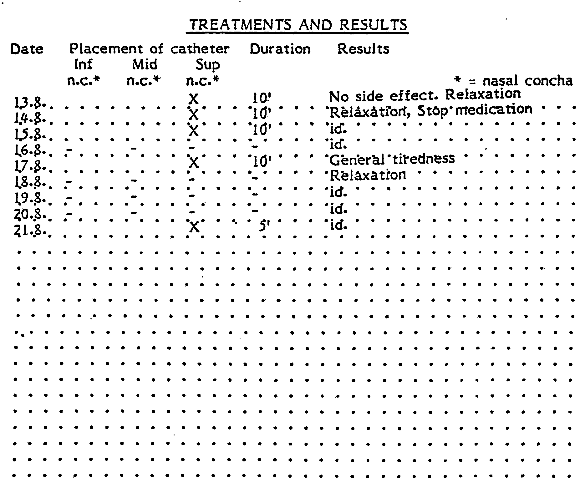
Figure 1 is a schematic circuit diagram of an apparatus including an applicator; Figure 2 shows a specific form of an endonasal probe applicator, adapted to be inserted into each rostrii of a subject; Figure 3 shows various positions in the endonasal cavity where an applicator, as in Figure 1 may be located so that the brain of the subject receives electrically induced energy from the applicator;
Figure 4 shows a positioning of an applicator in the mouth of a subject; Figure 5 shows a side elevation of a specific form of an applicator for positioning in the mouth of a subject, as in Figure 4; Figure 6 shows a plan view of the applicator of Figure 5; and Figures 7a and 7b respectively show plan and side elevations of an energy applicator.
Referring now to Figure 1 of the drawings, this comprises, by way of example, a device including a plurality of types of electrically induced energies. Thus, the apparatus represented in Figure 1 comprises a low-frequency d.c. pulse generator 1 capable of producing current pulses in the form of a rectangular signal having, for example, a pulse width of the order 0.5 to 5 milliseconds with a frequency of 10 to 100 Hertz at a voltage of the order of some tens of millivolts, preferably from 10 to 100 millivolts, a high-frequency a.c. generator 2, modulated at low-frequency, capable of producing an electrical signal formed of sinusoidal wave or square pulses having a frequency of the order of some tens of Megahertz, preferably from 20 to 100 Megahertz, modulated in sinusoidal form with a frequency of modulation of the order of some tens of Hertz, preferably from 2.5 to 6000 Hertz, the power of this generator 2 being preferably of the order of 0.1 to 1 Watt and a generator 3 which is a laser emitter comprising, for example, a Helium-Neon tube capable
of emitting a coherent and monochromatic red light beam having a wavelength of 632.8 nanometers in the form of a light signal modulated with a frequency variable from 1 to 160 Hertz. In replacement of the Helium-Neon tube one might equally employ any other suitable source of coherent monochomatic light, for example, a Gallium Arsenide photodiode.
A control and display device 4 is connected to the generators 1 and 2, and to laser emitter 3 by respective control signal transmission lines 5, 6 and 7. The control and display device 4 enables the emission of energy by the generators and the laser emitter to be controlled in accordance with the needs of the treatment which it is desired to carry out by means of the apparatus in accordance with a pre-established programme in which the characteristics of the luminous electrical signals are made to vary as well as the duration of emission and the sequence of application of each of the signals, and the data of the programme so chosen to be displayed. The generators 1 and 2 and the laser emitter 3 are respectively connected to a probe 8 for application of energy, by way of the lines 10 and 11 for transmission of electrical signals and of an optical fibre line 12 for transmission of luminous signals and of a switch 9 (shown schematically in Figure 1) which is likewise controlled by the control and display device 4 by way of a control signal transmission line 13.
The switch 9 is arranged so as to enable the signal transmission lines 10, 11 and 12 to be connected individually or simultaneously to the applicator 8 for application of energy, the connection between the applicator 8 and the switch 9 being effected by means of a line 14 for mixed transmission of electrical and luminous signals where desired. The return of the electric current is effected by means of an electrically conductive electrode (see Figures 7a, 7b, 7c) during the application of the electrical signals and is connected to the generators 1 and 2 by an electrically conductive line. The applicator 8 shown in Figure 1 comprises a middle portion 20 consisting of an electrically insulating sheath which is flexible or semi-rigid and, for example, of plastics matter, surrounding an optical fibre line for the transmissi on of luminous signals, round which may be wound an electrically conductive line for transmission of electrical signals, a front portion 18 intended for placing inside the mouth or endonasal cavity of a patient and a rear portion 19 for connection with the mixed transmission line 14. The front portion 18 of the probe 8 is of a material which is a good electrical conductor, for example of copper or brass.
A rounded tip 23 of matter which is transparent or translucent at least for the radiation transmitted to surround an end portion of the optical fibre line for transmission of luminous signals.
The rear portion 19 of the applicator 8 comprises a material which is a good electrical conductor, which is for example copper or brass.
It will be understood that the front portion 18 of the applicator 8 enables the electrically induced energy to be applied individually or simultaneously, such as in the form of an electromagnetic wave energy or an electric current to the same region of the brain of the subject being treated. The energy applicator 78 shown in Figure 2 has the general shape of a fork composed of a middle portion 70, two curved arms 78a and 78b and a cylindrical connector rod 79 enabling electrical connection of the applicator to the generators of pulses of electric current and/or of electro-magnetic waves. The applicator 78 may consist of one single piece moulded from plastics material entirely or partially covered with an electrically conductive layer (not shown).
Numerous variations may be applied to the form of the applicator 78, especially as for as the spacing, slope and radii of curvature of the arms 78a and 78b are concerned. The dimensions of the applicator may likewise vary, especially in order to allow adaption to the dimensions of the users' nasal cavities as well as to the different exact points of application of the energy. On the other hand the applicator 78 might be equipped with one or more lines for transmission of energy in the form of luminous waves, to play the same part as the optical fibre line in the applicator 8 discussed above. For example, such a line for transmission of energy in the form of luminous waves might consist of a bundle of optical fibres which is incorporated in the body of the applicator 78 which connects the connector rod 79 to the ends of the arms 78a and 78b by dividing in the middle portion 70 into two bundles which continue respectively inside the arms 78a and 78b out to the free ends 80a and 80b of the latter, so as to lie flush with the rounded surfaces of these ends.
The support 81 shown in Figure 3 is illustrative of a means for controlling the depth of penetration and the angle of penetration of a pair of applicators 8a and 8b. Two side sections of the support 81 are rotable about an axis relative to one another so that the angle of penetration of the applicators 8a and 8b may be adjusted.
In Figure 4, there is shown a buccal applicator shaped to fit against the palate of a subject, which in this embodiment reaches rearwardly to the cartilaginous portion of the soft palate. The front portion of the applicator 138 comprises a clip 140 arranged so as to be able to be placed over the front teeth, so as to enable easy positioning of the applicator. The applicator may in addition be kept in position by pressure applied by the tongue. The electrical and electro-magnetic connection of the energy applicator 138 with the energy transmission line 14 (Figure 1) is effected by way of a connector portion 141 playing the same role as the portion 19 of the energy applicator 8 shown in Figure 1 or the portion 79 of the applicator 78 shown in Figure 2, the surface of the applicator 138 being entirely or partially covered with an electrically conductive layer.
The buccal energy applicator 138 may be equipped with one or more lines for transmission of luminous signals, consisting, for example, of one or more optical fibres or bundles of optical fibres incorporated into the body of the applicator and lying flush with the surface.
Figure 5 of the drawings shows an applicator for being held in the hand or between the teeth of a subject. The applicator comprises a clip or stop 140 as is also shown in Figure 4 for abutting against the front teeth of a subject, thereby facilitating positioning of the applicator. The applicator shown in Figure 5 comprises a body portion 142 which serves as a handle and also serves as a housing to house electric circuitry, one or more generators as in Figure 1, and optionally batteries for supplying power to the one or more generators. A thumb switch 144 is provided for activating the one or more generators. Alternatively or additionally, the applicator may be
provided with power lines 146 for connection to a power source, which may serve to activate generators or to charge rechargeable accumulators within the housing 142. Energy from the one or more generators and in particular electromagnetic energy of the nature discussed above is conveyed to emmitter 148, which is shaped to fit against the polate of a subject, as shown in Figure 4. The housing 142 and surround 150 of the emmitter 148 is of electrically non-conductive plastics material. Where desired, an optical fibre bundle may also be arranged to terminate at the surface of the transmitter 148.
Figures 7(a) and 7(b) show the presently most prefered form of energy applicator for placement in the mouth of a subject. This comprises a transmitter section 200 which is split by cut-outs 202 providing effective elongated antenna sections 204 suitable for transmitting radio-type waves of the nature discussed above. The central section 206 of this energy applicator conveniently carries a clip 208 by means of which the applicator may be clipped to front teeth of the subject and thus held in position. The applicator is conveniently of disparable nature and is preferably constructed of plastics material coated with an electrically conductive layer, such as of metal. The conductive layer is preferably applied only to one (upper) side of the transmitter section 200 so that emmission of waver is predominantly towards the brain as required in the treatment. Hearwardly of the transmitter section 200 the applicator is also electrically conductive and terminates with connection means 210 for connection directly to the generator or to a line from the generator. The section 212 of the applicator is for holding and placing the applicator between thumb and fringers.
Studies made with the aid of an encephologram of patients treated with apparatus of the invention, have reflected that the method has a favourable normalising effect on the encephologram similar to the effect of a tranquilizer such as a benzodiazepine derivative. The general conclusion of the encephologram studies is that the therapy is effective in the treatment or a variety of different clinical states of disorders of the vegetative ervous system. The specific case reports above all refer to endonasal application. However, more recent studies, carried out with available endonasal probes inserted into the mouth of the subject rather than into the endonasal cavity, have reflected that entirely satisfactory results are achieved when the applicator is placed in the mouth of the subject. On the other hand, tests carried out with placement of the applicator outside of the head show little to no effect.
Claims
1. Apparatus for treating a subject suffering from anxiety neurosis and any accompanying neurovegetative disorder, comprising a generator of electrically induced energy capable of influencing the vegetative nervous system of the brain, and an energy applicator adapted to be placed in the mouth or endonasal cavity of the subject for applying electrically induced energy received from the generator to the brain of the subject and in particular to the limbic system thereof.
2. Apparatus according to claim 1, in which the generator is adapted to generate an electromagnetic wave or field energy.
3. Apparatus according to claim 2, in which the generator is adapted to generate rectangular d.c. pulses having a pulse duration of from 0.5 to 5 milliseconds at a voltage of from 10 to 100 millivolts with a repetition frequency of from 10 to 100 Hertz.
4. Apparatus according to claim 2, in which the generator is adapted to generate a.c. pulses having a frequency of from 20 to 100 Megahertz modulated with a frequency of modulation of from 2.5 to 6000 Hertz.
5. Apparatus according to any one of the preceding claims, in which the apparatus is of portable pocket size including a housing for housing the electronic circuitry which provides the electrically induced energy, and the energy applicator extending from the housing.
6. Apparatus according to claim 5, in which the housing includes a power source in the form of batteries for energising the generator.
7. Apparatus according to claim 6, in which the batteries are rechargeable accumulators, and in which electrically conductive wires are provided for connection to a power source for recharging the accumulators.
8. Apparatus according to any one of claims 1 to 5, in which the apparatus is provided with electrically conductive wires for connection to a power source for energising the generator.
9. Apparatus according to any one of the preceding claims, in which the energy applicator is shaped to fit against the palate of the subject.
10. Apparatus according to any one of the preceding claims, in which clip means is provided for clipping the energy applicator onto front teeth of the subject so that the energy applicator is maintained in position in the mouth of the subject.
11. Apparatus according to any one of the preceding claims, in which the energy applicator is a transmitter antenna.
12. Apparatus according to claim 2, in which the generator is adapted to generate electromagnetic waves in the form of a beam of coherent light having a wavelength which corresponds to the visible band of the spectrum of electromagnetic radiation.
Priority Applications (1)
| Application Number | Priority Date | Filing Date | Title |
|---|---|---|---|
| BR8506746A BR8506746A (en) | 1984-05-21 | 1985-05-21 | APPLIANCE FOR THE TREATMENT OF NEUROVEGETATIVE DISORDERS |
Applications Claiming Priority (2)
| Application Number | Priority Date | Filing Date | Title |
|---|---|---|---|
| US612,544 | 1984-05-21 | ||
| US06/612,544 US4649935A (en) | 1984-05-21 | 1984-05-21 | Method of treating neurovegetative disorders and apparatus therefor |
Publications (1)
| Publication Number | Publication Date |
|---|---|
| WO1985005278A1 true WO1985005278A1 (en) | 1985-12-05 |
Family
ID=24453617
Family Applications (1)
| Application Number | Title | Priority Date | Filing Date |
|---|---|---|---|
| PCT/EP1985/000241 WO1985005278A1 (en) | 1984-05-21 | 1985-05-21 | Apparatus for treating neurovegetative disorders |
Country Status (7)
| Country | Link |
|---|---|
| US (2) | US4649935A (en) |
| EP (1) | EP0164016B1 (en) |
| JP (1) | JPH064099B2 (en) |
| AT (1) | ATE58299T1 (en) |
| BR (1) | BR8506746A (en) |
| DE (1) | DE3580518D1 (en) |
| WO (1) | WO1985005278A1 (en) |
Cited By (4)
| Publication number | Priority date | Publication date | Assignee | Title |
|---|---|---|---|---|
| WO1990009206A2 (en) * | 1989-02-20 | 1990-08-23 | Solar Wide Industrial Ltd. | Dental aid |
| US5441528A (en) * | 1992-09-25 | 1995-08-15 | Symtonic, S.A. | Method and system for applying low energy emission therapy |
| US5792067A (en) * | 1995-11-21 | 1998-08-11 | Karell; Manuel L. | Apparatus and method for mitigating sleep and other disorders through electromuscular stimulation |
| USRE36120E (en) * | 1992-11-12 | 1999-03-02 | Karell; Manuel L. | Snopper--the snoring stopper anti-snoring mouth device |
Families Citing this family (55)
| Publication number | Priority date | Publication date | Assignee | Title |
|---|---|---|---|---|
| BR8707351A (en) * | 1986-06-16 | 1988-09-13 | Zion Educational Found | APPLIANCE AND PROCESS FOR ISSUE OF PRESCRIPTIVE SIGNAL WAVE FORM, APPLIANCE AND APPLICATOR PROCESS OF ELECTRIC SIGNALS, PROCESS FOR ISSUE OF PRESCRIPTIVE ELECTRIC WAVE FORM AND PROCESS FOR ISSUE OF PRESCRIPTION ELECTRIC SIGNAL |
| CA1334541C (en) * | 1988-05-04 | 1995-02-21 | Michael James Williams Brennan | Treatment of sleep disorders and alleviating disruption of circadian rhythms |
| KR920702820A (en) * | 1989-12-11 | 1992-10-28 | 루이스 에이. 산타나블랑크 | Laser treatment apparatus and method used for systemic diseases |
| EP0538510A1 (en) * | 1991-10-23 | 1993-04-28 | Symtonic S.A. | Apparatus for low energy emission therapy |
| DE4340997A1 (en) * | 1993-12-02 | 1995-06-22 | Alexander Wunsch | Incorporation device for electromagnetic waves used in healing therapy |
| US5533527A (en) * | 1994-04-20 | 1996-07-09 | Columbia University | Treatment method for depressive and neurovegetative disorders |
| WO2000007658A1 (en) * | 1998-08-06 | 2000-02-17 | Shmuel Peltz | Method and appliances for electrostimulation |
| JP2002528192A (en) * | 1998-10-23 | 2002-09-03 | イッサチャロフ、マイケル | Neuro-immuno-endocrine modulators and therapy |
| SE517478C2 (en) * | 1999-04-30 | 2002-06-11 | Valinge Aluminium Ab | Locking system for mechanical hoisting of floorboards, floorboard provided with the locking system and method for producing mechanically foldable floorboards |
| HU224941B1 (en) * | 2001-08-10 | 2006-04-28 | Bgi Innovacios Kft | Phototerapy apparatus |
| US6954668B1 (en) * | 2001-10-11 | 2005-10-11 | Cuozzo John W | Apparatus and method for intra-oral stimulation of the trigeminal nerve |
| US6872221B2 (en) * | 2002-08-05 | 2005-03-29 | Larry Robert Lytle | Therapeutic low level laser apparatus and method |
| US20040226556A1 (en) * | 2003-05-13 | 2004-11-18 | Deem Mark E. | Apparatus for treating asthma using neurotoxin |
| US20050021090A1 (en) * | 2003-07-23 | 2005-01-27 | Eleanor Schuler | Method and device for regulation of limbic system of the brain by means of neuro-electrical coded signals |
| US8214047B2 (en) * | 2004-09-27 | 2012-07-03 | Advanced Neuromodulation Systems, Inc. | Method of using spinal cord stimulation to treat gastrointestinal and/or eating disorders or conditions |
| US8109981B2 (en) * | 2005-01-25 | 2012-02-07 | Valam Corporation | Optical therapies and devices |
| US20070073354A1 (en) | 2005-09-26 | 2007-03-29 | Knudson Mark B | Neural blocking therapy |
| US7725188B2 (en) * | 2006-02-10 | 2010-05-25 | Electrocore Llc | Electrical stimulation treatment of hypotension |
| US20110125203A1 (en) * | 2009-03-20 | 2011-05-26 | ElectroCore, LLC. | Magnetic Stimulation Devices and Methods of Therapy |
| US9037247B2 (en) | 2005-11-10 | 2015-05-19 | ElectroCore, LLC | Non-invasive treatment of bronchial constriction |
| US8041428B2 (en) | 2006-02-10 | 2011-10-18 | Electrocore Llc | Electrical stimulation treatment of hypotension |
| US7747324B2 (en) * | 2005-11-10 | 2010-06-29 | Electrocore Llc | Electrical stimulation treatment of bronchial constriction |
| US8812112B2 (en) * | 2005-11-10 | 2014-08-19 | ElectroCore, LLC | Electrical treatment of bronchial constriction |
| CN101400402A (en) | 2006-02-10 | 2009-04-01 | 电子核心公司 | Electrical stimulation treatment of hypotension |
| US20100241188A1 (en) * | 2009-03-20 | 2010-09-23 | Electrocore, Inc. | Percutaneous Electrical Treatment Of Tissue |
| US20080027506A1 (en) * | 2006-07-27 | 2008-01-31 | Cuozzo John W | Apparatus and method for pain control through nerve stimulation by an intra-oral source |
| EP1974769A1 (en) | 2007-03-27 | 2008-10-01 | Boris Pasche | Electronic system for influencing cellular functions in a warm-blooded mammalian subject |
| US8333756B2 (en) * | 2007-10-24 | 2012-12-18 | Paul Weisbart | Scalar laser therapy apparatus |
| US8236037B2 (en) * | 2007-10-24 | 2012-08-07 | Paul Weisbart | Scalar laser therapy apparatus |
| US20090204173A1 (en) | 2007-11-05 | 2009-08-13 | Zi-Ping Fang | Multi-Frequency Neural Treatments and Associated Systems and Methods |
| US8483831B1 (en) | 2008-02-15 | 2013-07-09 | Holaira, Inc. | System and method for bronchial dilation |
| EP2529686B1 (en) | 2008-05-09 | 2015-10-14 | Holaira, Inc. | System for treating a bronchial tree |
| US8255057B2 (en) | 2009-01-29 | 2012-08-28 | Nevro Corporation | Systems and methods for producing asynchronous neural responses to treat pain and/or other patient conditions |
| US9327121B2 (en) | 2011-09-08 | 2016-05-03 | Nevro Corporation | Selective high frequency spinal cord modulation for inhibiting pain, including cephalic and/or total body pain with reduced side effects, and associated systems and methods |
| EP2421600B1 (en) | 2009-04-22 | 2014-03-05 | Nevro Corporation | Spinal cord modulation systems for inducing paresthetic and anesthetic effects |
| ES2624748T3 (en) | 2009-04-22 | 2017-07-17 | Nevro Corporation | Selective high frequency modulation of the spinal cord for pain inhibition with reduced side effects, and associated systems and methods |
| US8498710B2 (en) | 2009-07-28 | 2013-07-30 | Nevro Corporation | Linked area parameter adjustment for spinal cord stimulation and associated systems and methods |
| US9649153B2 (en) | 2009-10-27 | 2017-05-16 | Holaira, Inc. | Delivery devices with coolable energy emitting assemblies |
| US8911439B2 (en) | 2009-11-11 | 2014-12-16 | Holaira, Inc. | Non-invasive and minimally invasive denervation methods and systems for performing the same |
| CA2780608C (en) | 2009-11-11 | 2019-02-26 | Innovative Pulmonary Solutions, Inc. | Systems, apparatuses, and methods for treating tissue and controlling stenosis |
| US8649874B2 (en) | 2010-11-30 | 2014-02-11 | Nevro Corporation | Extended pain relief via high frequency spinal cord modulation, and associated systems and methods |
| EP2772278B1 (en) * | 2011-10-25 | 2017-08-02 | Kanazawa Medical University | Light exposure device for improving cognitive symptoms and depression symptoms |
| US8676331B2 (en) | 2012-04-02 | 2014-03-18 | Nevro Corporation | Devices for controlling spinal cord modulation for inhibiting pain, and associated systems and methods, including controllers for automated parameter selection |
| US9833614B1 (en) | 2012-06-22 | 2017-12-05 | Nevro Corp. | Autonomic nervous system control via high frequency spinal cord modulation, and associated systems and methods |
| WO2014078658A1 (en) | 2012-11-16 | 2014-05-22 | Paul Weisbart | Quantum field system for treatment of human tissue |
| US9398933B2 (en) | 2012-12-27 | 2016-07-26 | Holaira, Inc. | Methods for improving drug efficacy including a combination of drug administration and nerve modulation |
| WO2014172693A2 (en) * | 2013-04-19 | 2014-10-23 | Oculeve, Inc. | Nasal stimulation devices and methods |
| US9895539B1 (en) | 2013-06-10 | 2018-02-20 | Nevro Corp. | Methods and systems for disease treatment using electrical stimulation |
| US10149978B1 (en) | 2013-11-07 | 2018-12-11 | Nevro Corp. | Spinal cord modulation for inhibiting pain via short pulse width waveforms, and associated systems and methods |
| US11318310B1 (en) | 2015-10-26 | 2022-05-03 | Nevro Corp. | Neuromodulation for altering autonomic functions, and associated systems and methods |
| AU2017211121B2 (en) | 2016-01-25 | 2022-02-24 | Nevro Corp. | Treatment of congestive heart failure with electrical stimulation, and associated systems and methods |
| US10799701B2 (en) | 2016-03-30 | 2020-10-13 | Nevro Corp. | Systems and methods for identifying and treating patients with high-frequency electrical signals |
| US11446504B1 (en) | 2016-05-27 | 2022-09-20 | Nevro Corp. | High frequency electromagnetic stimulation for modulating cells, including spontaneously active and quiescent cells, and associated systems and methods |
| WO2020150647A1 (en) | 2019-01-17 | 2020-07-23 | Nevro Corp. | Sensory threshold and/or adaptation for neurological therapy screening and/or parameter selection, and associated systems and methods |
| US11590352B2 (en) | 2019-01-29 | 2023-02-28 | Nevro Corp. | Ramped therapeutic signals for modulating inhibitory interneurons, and associated systems and methods |
Citations (7)
| Publication number | Priority date | Publication date | Assignee | Title |
|---|---|---|---|---|
| FR2066680A5 (en) * | 1969-10-28 | 1971-08-06 | Respub Upravlen | |
| US4033356A (en) * | 1975-08-20 | 1977-07-05 | Hakuju Institute For Health Science Co., Ltd. | Apparatus for therapeutical treatment and stimulation of muscles by low-frequency oscillating electric current |
| FR2340743A1 (en) * | 1976-02-13 | 1977-09-09 | Traitement Information Tech Nl | Electric sleep inducing apparatus - has impulse generator supplying two leads each ending at electrodes |
| FR2398509A1 (en) * | 1977-07-29 | 1979-02-23 | Mo Oblast I Akusher | DEVICE FOR ACTING BY IMPULSE CURRENTS ON THE CENTRAL NERVOUS SYSTEM OF AN INDIVIDUAL |
| US4153060A (en) * | 1978-03-15 | 1979-05-08 | University Of Pennsylvania | Method and apparatus for electrically enhanced bone growth and tooth movement |
| FR2535974A1 (en) * | 1982-11-15 | 1984-05-18 | Symtonic Sa | APPARATUS FOR TREATING LIVING FABRICS BY STIMULATION USING ELECTRIC CURRENT PULSES AND / OR ELECTROMAGNETIC WAVES |
| EP0122102A1 (en) * | 1983-04-01 | 1984-10-17 | Biosonics, Inc. | Apparatus for stimulating salivation |
Family Cites Families (11)
| Publication number | Priority date | Publication date | Assignee | Title |
|---|---|---|---|---|
| US535905A (en) * | 1895-03-19 | william p | ||
| CA774178A (en) * | 1967-12-19 | Borisovich Hoody Jusha | Method of treating various diseases by sleep and a device for the realisation of the method | |
| US1257555A (en) * | 1914-06-25 | 1918-02-26 | Vreeland Apparatus Company | Method of producing analgesia. |
| US1967815A (en) * | 1933-03-25 | 1934-07-24 | Frieberg Max | Diathermy apparatus |
| US3255753A (en) * | 1963-03-22 | 1966-06-14 | Nat Patent Dev Corp | Electrical sleep machine and sleep inducing method |
| FR1554569A (en) * | 1966-01-19 | 1969-01-24 | ||
| US3464416A (en) * | 1967-08-25 | 1969-09-02 | Williams Instruments | Sleep inducing method and headpiece |
| US3762396A (en) * | 1970-10-30 | 1973-10-02 | United Biscuits Ltd | Method and apparatus for inducing sleep by applying electrical pulses to plural portions of the head |
| DK155420C (en) * | 1979-05-10 | 1989-10-09 | Rion Co | ARTIFICIAL GANE |
| US4305402A (en) * | 1979-06-29 | 1981-12-15 | Katims Jefferson J | Method for transcutaneous electrical stimulation |
| JPS5643744A (en) * | 1979-09-18 | 1981-04-22 | Seiko Epson Corp | Manufacture of semiconductor device |
-
1984
- 1984-05-21 US US06/612,544 patent/US4649935A/en not_active Expired - Fee Related
-
1985
- 1985-05-21 AT AT85106242T patent/ATE58299T1/en not_active IP Right Cessation
- 1985-05-21 JP JP60502672A patent/JPH064099B2/en not_active Expired - Lifetime
- 1985-05-21 DE DE8585106242T patent/DE3580518D1/en not_active Expired - Fee Related
- 1985-05-21 EP EP85106242A patent/EP0164016B1/en not_active Expired - Lifetime
- 1985-05-21 WO PCT/EP1985/000241 patent/WO1985005278A1/en unknown
- 1985-05-21 BR BR8506746A patent/BR8506746A/en not_active IP Right Cessation
-
1987
- 1987-03-16 US US07/027,181 patent/US4765322A/en not_active Expired - Fee Related
Patent Citations (7)
| Publication number | Priority date | Publication date | Assignee | Title |
|---|---|---|---|---|
| FR2066680A5 (en) * | 1969-10-28 | 1971-08-06 | Respub Upravlen | |
| US4033356A (en) * | 1975-08-20 | 1977-07-05 | Hakuju Institute For Health Science Co., Ltd. | Apparatus for therapeutical treatment and stimulation of muscles by low-frequency oscillating electric current |
| FR2340743A1 (en) * | 1976-02-13 | 1977-09-09 | Traitement Information Tech Nl | Electric sleep inducing apparatus - has impulse generator supplying two leads each ending at electrodes |
| FR2398509A1 (en) * | 1977-07-29 | 1979-02-23 | Mo Oblast I Akusher | DEVICE FOR ACTING BY IMPULSE CURRENTS ON THE CENTRAL NERVOUS SYSTEM OF AN INDIVIDUAL |
| US4153060A (en) * | 1978-03-15 | 1979-05-08 | University Of Pennsylvania | Method and apparatus for electrically enhanced bone growth and tooth movement |
| FR2535974A1 (en) * | 1982-11-15 | 1984-05-18 | Symtonic Sa | APPARATUS FOR TREATING LIVING FABRICS BY STIMULATION USING ELECTRIC CURRENT PULSES AND / OR ELECTROMAGNETIC WAVES |
| EP0122102A1 (en) * | 1983-04-01 | 1984-10-17 | Biosonics, Inc. | Apparatus for stimulating salivation |
Cited By (7)
| Publication number | Priority date | Publication date | Assignee | Title |
|---|---|---|---|---|
| WO1990009206A2 (en) * | 1989-02-20 | 1990-08-23 | Solar Wide Industrial Ltd. | Dental aid |
| WO1990009206A3 (en) * | 1989-02-20 | 1990-11-29 | Solar Wide Ind Ltd | Dental aid |
| US5441528A (en) * | 1992-09-25 | 1995-08-15 | Symtonic, S.A. | Method and system for applying low energy emission therapy |
| US5501704A (en) * | 1992-09-25 | 1996-03-26 | Symtonic, S.A. | Method for applying low energy emission therapy |
| US5634939A (en) * | 1992-09-25 | 1997-06-03 | Symtonic, S.A. | Program storage device usable with a system for applying low energy emission therapy |
| USRE36120E (en) * | 1992-11-12 | 1999-03-02 | Karell; Manuel L. | Snopper--the snoring stopper anti-snoring mouth device |
| US5792067A (en) * | 1995-11-21 | 1998-08-11 | Karell; Manuel L. | Apparatus and method for mitigating sleep and other disorders through electromuscular stimulation |
Also Published As
| Publication number | Publication date |
|---|---|
| BR8506746A (en) | 1986-09-23 |
| DE3580518D1 (en) | 1990-12-20 |
| JPS61502236A (en) | 1986-10-09 |
| ATE58299T1 (en) | 1990-11-15 |
| JPH064099B2 (en) | 1994-01-19 |
| EP0164016B1 (en) | 1990-11-14 |
| US4765322A (en) | 1988-08-23 |
| EP0164016A1 (en) | 1985-12-11 |
| US4649935A (en) | 1987-03-17 |
Similar Documents
| Publication | Publication Date | Title |
|---|---|---|
| EP0164016A1 (en) | Apparatus for treating neurovegatative disorders | |
| JPS60500241A (en) | Device for treating biological tissue by stimulating current pulses and/or electromagnetic waves | |
| US6916329B1 (en) | Optical/electrical acupuncture needle and system | |
| EP0461151B1 (en) | Electro-therapy apparatus | |
| US6023642A (en) | Compact transcutaneous electrical nerve stimulator | |
| EP1282457B1 (en) | Apparatus for electromedical therapy | |
| US6520903B1 (en) | Multiple mode photonic stimulation device | |
| US20060089688A1 (en) | Method and apparatus to reduce wrinkles through application of radio frequency energy to nerves | |
| BRPI0713151A2 (en) | noninvasive neurostimulatory system | |
| AU2001252069A1 (en) | Apparatus for electromedical therapy | |
| BR9007805A (en) | ELECTRODE TO PROVIDE TRANSCRANIAL ELECTRO-THERAPY, ESPECIALLY THROUGH THE PATIENT'S EAR LOBULES, APPLIANCE TO GENERATE AN ELECTRIC SIGN FOR USE IN TRANSCRANIAL ELECTRO-THERAPY, AND THE PROCESS OF APPLYING TRANS-CRANE ELECTRO-THERAPY TO A PATIENT | |
| IE912227A1 (en) | Method and device for the treatment of epilepsy | |
| JP2012502719A (en) | Head electrical stimulation electrode unit | |
| EP0184928B1 (en) | Hygienic attachments for therapy lasers | |
| US11116973B1 (en) | System and method for a medical device | |
| CN105451679A (en) | Device and method for fractional RF treatment of the skin | |
| CA2195046A1 (en) | Ear mold for stimulating acupuncture points | |
| KR20150102357A (en) | Laser electrical fusion treating apparatus | |
| US20210146131A1 (en) | Deep tissue pulsed electromagnetic field therapy apparatus and method of use thereof | |
| CN216124812U (en) | Traditional chinese medical science auricular point stimulating equipment | |
| JPH06197989A (en) | Low-energy radiotherapeutic device | |
| KR200309021Y1 (en) | Low frequency stimulator | |
| Stephenson | A bipolar electrode for electromyography of limb muscles of small animals | |
| CA1168710A (en) | Electrical pulse acupressure system | |
| RU18477U1 (en) | DEVICE FOR TREATMENT OF PROSTATOPATHY |
Legal Events
| Date | Code | Title | Description |
|---|---|---|---|
| AK | Designated states |
Designated state(s): BR JP |