WO1998058599A1 - Implant de dilatation intravasculaire a deflecteur - Google Patents
Implant de dilatation intravasculaire a deflecteur Download PDFInfo
- Publication number
- WO1998058599A1 WO1998058599A1 PCT/IB1998/000948 IB9800948W WO9858599A1 WO 1998058599 A1 WO1998058599 A1 WO 1998058599A1 IB 9800948 W IB9800948 W IB 9800948W WO 9858599 A1 WO9858599 A1 WO 9858599A1
- Authority
- WO
- WIPO (PCT)
- Prior art keywords
- deflector
- artery
- stent according
- stent
- wall
- Prior art date
Links
Classifications
-
- A—HUMAN NECESSITIES
- A61—MEDICAL OR VETERINARY SCIENCE; HYGIENE
- A61F—FILTERS IMPLANTABLE INTO BLOOD VESSELS; PROSTHESES; DEVICES PROVIDING PATENCY TO, OR PREVENTING COLLAPSING OF, TUBULAR STRUCTURES OF THE BODY, e.g. STENTS; ORTHOPAEDIC, NURSING OR CONTRACEPTIVE DEVICES; FOMENTATION; TREATMENT OR PROTECTION OF EYES OR EARS; BANDAGES, DRESSINGS OR ABSORBENT PADS; FIRST-AID KITS
- A61F2/00—Filters implantable into blood vessels; Prostheses, i.e. artificial substitutes or replacements for parts of the body; Appliances for connecting them with the body; Devices providing patency to, or preventing collapsing of, tubular structures of the body, e.g. stents
- A61F2/82—Devices providing patency to, or preventing collapsing of, tubular structures of the body, e.g. stents
- A61F2/86—Stents in a form characterised by the wire-like elements; Stents in the form characterised by a net-like or mesh-like structure
-
- A—HUMAN NECESSITIES
- A61—MEDICAL OR VETERINARY SCIENCE; HYGIENE
- A61F—FILTERS IMPLANTABLE INTO BLOOD VESSELS; PROSTHESES; DEVICES PROVIDING PATENCY TO, OR PREVENTING COLLAPSING OF, TUBULAR STRUCTURES OF THE BODY, e.g. STENTS; ORTHOPAEDIC, NURSING OR CONTRACEPTIVE DEVICES; FOMENTATION; TREATMENT OR PROTECTION OF EYES OR EARS; BANDAGES, DRESSINGS OR ABSORBENT PADS; FIRST-AID KITS
- A61F2/00—Filters implantable into blood vessels; Prostheses, i.e. artificial substitutes or replacements for parts of the body; Appliances for connecting them with the body; Devices providing patency to, or preventing collapsing of, tubular structures of the body, e.g. stents
- A61F2/01—Filters implantable into blood vessels
- A61F2002/016—Filters implantable into blood vessels made from wire-like elements
-
- A—HUMAN NECESSITIES
- A61—MEDICAL OR VETERINARY SCIENCE; HYGIENE
- A61F—FILTERS IMPLANTABLE INTO BLOOD VESSELS; PROSTHESES; DEVICES PROVIDING PATENCY TO, OR PREVENTING COLLAPSING OF, TUBULAR STRUCTURES OF THE BODY, e.g. STENTS; ORTHOPAEDIC, NURSING OR CONTRACEPTIVE DEVICES; FOMENTATION; TREATMENT OR PROTECTION OF EYES OR EARS; BANDAGES, DRESSINGS OR ABSORBENT PADS; FIRST-AID KITS
- A61F2/00—Filters implantable into blood vessels; Prostheses, i.e. artificial substitutes or replacements for parts of the body; Appliances for connecting them with the body; Devices providing patency to, or preventing collapsing of, tubular structures of the body, e.g. stents
- A61F2/02—Prostheses implantable into the body
- A61F2/04—Hollow or tubular parts of organs, e.g. bladders, tracheae, bronchi or bile ducts
- A61F2/06—Blood vessels
- A61F2002/068—Modifying the blood flow model, e.g. by diffuser or deflector
-
- A—HUMAN NECESSITIES
- A61—MEDICAL OR VETERINARY SCIENCE; HYGIENE
- A61F—FILTERS IMPLANTABLE INTO BLOOD VESSELS; PROSTHESES; DEVICES PROVIDING PATENCY TO, OR PREVENTING COLLAPSING OF, TUBULAR STRUCTURES OF THE BODY, e.g. STENTS; ORTHOPAEDIC, NURSING OR CONTRACEPTIVE DEVICES; FOMENTATION; TREATMENT OR PROTECTION OF EYES OR EARS; BANDAGES, DRESSINGS OR ABSORBENT PADS; FIRST-AID KITS
- A61F2210/00—Particular material properties of prostheses classified in groups A61F2/00 - A61F2/26 or A61F2/82 or A61F9/00 or A61F11/00 or subgroups thereof
- A61F2210/0004—Particular material properties of prostheses classified in groups A61F2/00 - A61F2/26 or A61F2/82 or A61F9/00 or A61F11/00 or subgroups thereof bioabsorbable
-
- A—HUMAN NECESSITIES
- A61—MEDICAL OR VETERINARY SCIENCE; HYGIENE
- A61F—FILTERS IMPLANTABLE INTO BLOOD VESSELS; PROSTHESES; DEVICES PROVIDING PATENCY TO, OR PREVENTING COLLAPSING OF, TUBULAR STRUCTURES OF THE BODY, e.g. STENTS; ORTHOPAEDIC, NURSING OR CONTRACEPTIVE DEVICES; FOMENTATION; TREATMENT OR PROTECTION OF EYES OR EARS; BANDAGES, DRESSINGS OR ABSORBENT PADS; FIRST-AID KITS
- A61F2210/00—Particular material properties of prostheses classified in groups A61F2/00 - A61F2/26 or A61F2/82 or A61F9/00 or A61F11/00 or subgroups thereof
- A61F2210/0095—Particular material properties of prostheses classified in groups A61F2/00 - A61F2/26 or A61F2/82 or A61F9/00 or A61F11/00 or subgroups thereof radioactive
-
- A—HUMAN NECESSITIES
- A61—MEDICAL OR VETERINARY SCIENCE; HYGIENE
- A61F—FILTERS IMPLANTABLE INTO BLOOD VESSELS; PROSTHESES; DEVICES PROVIDING PATENCY TO, OR PREVENTING COLLAPSING OF, TUBULAR STRUCTURES OF THE BODY, e.g. STENTS; ORTHOPAEDIC, NURSING OR CONTRACEPTIVE DEVICES; FOMENTATION; TREATMENT OR PROTECTION OF EYES OR EARS; BANDAGES, DRESSINGS OR ABSORBENT PADS; FIRST-AID KITS
- A61F2230/00—Geometry of prostheses classified in groups A61F2/00 - A61F2/26 or A61F2/82 or A61F9/00 or A61F11/00 or subgroups thereof
- A61F2230/0002—Two-dimensional shapes, e.g. cross-sections
- A61F2230/0004—Rounded shapes, e.g. with rounded corners
- A61F2230/0006—Rounded shapes, e.g. with rounded corners circular
-
- A—HUMAN NECESSITIES
- A61—MEDICAL OR VETERINARY SCIENCE; HYGIENE
- A61F—FILTERS IMPLANTABLE INTO BLOOD VESSELS; PROSTHESES; DEVICES PROVIDING PATENCY TO, OR PREVENTING COLLAPSING OF, TUBULAR STRUCTURES OF THE BODY, e.g. STENTS; ORTHOPAEDIC, NURSING OR CONTRACEPTIVE DEVICES; FOMENTATION; TREATMENT OR PROTECTION OF EYES OR EARS; BANDAGES, DRESSINGS OR ABSORBENT PADS; FIRST-AID KITS
- A61F2230/00—Geometry of prostheses classified in groups A61F2/00 - A61F2/26 or A61F2/82 or A61F9/00 or A61F11/00 or subgroups thereof
- A61F2230/0063—Three-dimensional shapes
- A61F2230/0073—Quadric-shaped
- A61F2230/008—Quadric-shaped paraboloidal
-
- A—HUMAN NECESSITIES
- A61—MEDICAL OR VETERINARY SCIENCE; HYGIENE
- A61F—FILTERS IMPLANTABLE INTO BLOOD VESSELS; PROSTHESES; DEVICES PROVIDING PATENCY TO, OR PREVENTING COLLAPSING OF, TUBULAR STRUCTURES OF THE BODY, e.g. STENTS; ORTHOPAEDIC, NURSING OR CONTRACEPTIVE DEVICES; FOMENTATION; TREATMENT OR PROTECTION OF EYES OR EARS; BANDAGES, DRESSINGS OR ABSORBENT PADS; FIRST-AID KITS
- A61F2230/00—Geometry of prostheses classified in groups A61F2/00 - A61F2/26 or A61F2/82 or A61F9/00 or A61F11/00 or subgroups thereof
- A61F2230/0063—Three-dimensional shapes
- A61F2230/0091—Three-dimensional shapes helically-coiled or spirally-coiled, i.e. having a 2-D spiral cross-section
-
- A—HUMAN NECESSITIES
- A61—MEDICAL OR VETERINARY SCIENCE; HYGIENE
- A61F—FILTERS IMPLANTABLE INTO BLOOD VESSELS; PROSTHESES; DEVICES PROVIDING PATENCY TO, OR PREVENTING COLLAPSING OF, TUBULAR STRUCTURES OF THE BODY, e.g. STENTS; ORTHOPAEDIC, NURSING OR CONTRACEPTIVE DEVICES; FOMENTATION; TREATMENT OR PROTECTION OF EYES OR EARS; BANDAGES, DRESSINGS OR ABSORBENT PADS; FIRST-AID KITS
- A61F2250/00—Special features of prostheses classified in groups A61F2/00 - A61F2/26 or A61F2/82 or A61F9/00 or A61F11/00 or subgroups thereof
- A61F2250/0058—Additional features; Implant or prostheses properties not otherwise provided for
- A61F2250/0067—Means for introducing or releasing pharmaceutical products into the body
-
- Y—GENERAL TAGGING OF NEW TECHNOLOGICAL DEVELOPMENTS; GENERAL TAGGING OF CROSS-SECTIONAL TECHNOLOGIES SPANNING OVER SEVERAL SECTIONS OF THE IPC; TECHNICAL SUBJECTS COVERED BY FORMER USPC CROSS-REFERENCE ART COLLECTIONS [XRACs] AND DIGESTS
- Y10—TECHNICAL SUBJECTS COVERED BY FORMER USPC
- Y10S—TECHNICAL SUBJECTS COVERED BY FORMER USPC CROSS-REFERENCE ART COLLECTIONS [XRACs] AND DIGESTS
- Y10S623/00—Prosthesis, i.e. artificial body members, parts thereof, or aids and accessories therefor
- Y10S623/902—Method of implanting
- Y10S623/903—Blood vessel
Definitions
- the present invention relates to an intravascular implant allowing the radial dilation of the arterial walls.
- These implants or dilators are known as a 'stent' in the field of transluminal angioplasty.
- Transluminal angioplasty consists in treating diseased areas of the arterial system by the introduction of devices, in particular catheters by the natural routes. This allows localized interventions without having to resort to conventional surgical interventions which, because of their heaviness, have numerous drawbacks for the patients. This technique is used in particular when diagnosing a narrowing or stenosis of the arteries.
- a catheter is then introduced through the femoral artery provided at its distal end with an inflatable angioplasty balloon.
- This catheter is then pushed and guided, under radioscopic control, through the arterial network to the diseased area of the artery. Once this area is reached, the balloon is inflated to dilate the narrowed area of the artery. This operation is repeated until it is observed, by means of radioscopic control, that the artery again has a sufficient diameter to ensure an acceptable blood flow.
- these interventions have certain drawbacks. In fact, clinical observations show that in around a third of the cases treated, the artery narrows again in a period of time between a few days and a few months. This phenomenon which is called 'restenosis' requires a new intervention on the diseased artery either by the same method, or by means of heavier surgical techniques.
- dilators or 'stents' in the artery to prevent it from narrowing again.
- These implants usually have a tubular structure open at the ends so as not to disturb the blood flow.
- These devices independently of their particular structure, generally have the following characteristics: they are radially extensible from a first diameter, allowing their introduction into the artery using a catheter, to a second larger diameter corresponding substantially to the diameter of the artery. After dilation of the artery, they are implanted in the latter and bear against the internal wall of the artery thus preventing, by an action mechanical, that the artery does not narrow again.
- these stents have a certain resistance to radial compression and thus keep the artery open while allowing the flow of blood.
- stents of two different types are commonly used. The former are deformed by the inflation of a balloon when they are put in place; the second stents are said to be self-expanding. Self-expanding stents do not require external mechanical action to pass from a first diameter during insertion, to a second larger diameter in the service position. This effect is obtained either by the use of shape memory material, such as Nitinol (registered trademark), or by spring effect.
- a stent which comprises a radioactive isotope to try to reduce the phenomenon of restenosis by radiotherapy.
- the surface of the stent in contact with the internal wall of the artery or vessel, includes an appropriate surface treatment allowing the local distribution of anti-thrombogenic chemicals.
- the object of the present invention is to remedy the drawbacks mentioned above by proposing a dilation implant promoting the reduction in the rate of restenosis, in particular by its action on the internal wall of the artery.
- Another object of the invention consists in the use of such a device for increasing the shear stress at the blood / wall interface in an artery or a blood vessel.
- the invention also relates to a process promoting the increase in shear stresses at the level of the arterial wall.
- the stent according to the present invention is distinguished for this purpose by the characteristics defined in claim 1.
- FIG. 1 is a schematic view illustrating the profile of the speeds in an artery without an implant.
- FIG. 2 is a schematic view illustrating the profile of the speeds in an artery comprising at its center a flow deflector.
- FIG. 3 is a graph illustrating the intimal relative shearing as a function of the dimensions of the deflector relative to the dimensions of the artery.
- Figure 4 is a side view of a stent according to the present invention.
- Figure 5 is an end view of the stent shown in Figure 4.
- intimal hyperplasia a cellular proliferation of intimal tissue
- intimal hyperplasia a cellular proliferation of intimal tissue
- the mechanisms of this reaction are not yet fully understood.
- intimal hyperplasia constitutes a key element of the success of the treatment of stenoses or occlusions of the arteries. It has been found in animals that intimal hyperplasia is reduced when the blood flow is high in the vessel concerned. On the other hand, when this flow is low the intimate layer increases. The same observation was made by cardiologists and radiologists who observed that after angioplasty, the stents remain open if the flow is high and that they tend to become blocked in the presence of low flow. blood.
- intimal hyperplasia is not a pathological process, but rather an adaptive response of the artery or the vessel which reshapes itself in order to maintain or restore an optimal level.
- shear stress at the wall The passage of blood through an artery created by friction of forces on the internal wall of the artery. When the flow is high, the shear forces are high on the endothelial cells of the artery wall. These forces are on the contrary weak in the presence of an insufficient flow.
- the shear stress on the internal wall is directly proportional to the flow rate (Q) and inversely proportional to the cube of the arterial diameter.
- intimal hyperplasia reduces the diameter of the artery in order to restore the normal value of the constraint. If low flow persists or gradually decreases, normal shear stress cannot be restored and intimal hyperplasia continues, ultimately leading to restenosis. On the contrary, if the flow is sufficient to restore a level of stress equal to, or even higher than, the normal stress, the intimal hyperplasia stops and the artery remains open durably. It appears from the observations set out above that to stop and stop intimal hyperplasia, it is necessary to locally increase the shear stress at the wall, particularly when the flow is low. The object of the invention is precisely to allow a significant local increase in the shear stress at the wall.
- FIG. 1 schematically illustrates the profile of the speeds in an artery of radius r 0
- FIG. 2 illustrates the same profile of the speeds when a flow deflector 1 of cylindrical shape is placed in the center of the artery.
- the deflector 1 deflects the current lines in the radial direction in the direction of the arterial walls 2 and leads to a greater radial gradient of speed in the vicinity of the walls 2 of the artery. As a result, the shear stress at the blood / wall interface is increased.
- the Navier-Stokes equation along the longitudinal axis of symmetry gives:
- the flow Q can then be calculated by simple integration
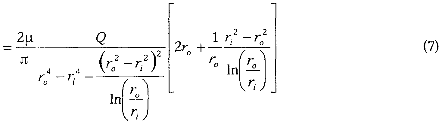
- Equation 6 can also be expressed as a function of flow rate Q using equation 4 for the pressure gradient
- the dependence of the shears with respect to the parameter ⁇ is represented in FIG. 3 on which the relative intimal shear is expressed on the ordinate and on the abscissa, the ratio between the radius of the deflector and the radius of the artery.
- the ratio between the radius of the deflector and that of the artery is one third, the surface occupied by the deflector represents only about 11% of the section of the artery and therefore constitutes only a negligible resistance to blood flow according to fluid mechanics.
- FIG. 4 shows a possible embodiment among many variants of a stent according to the present invention.
- This stent is in place in an artery or a vessel whose walls have been shown schematically 2. It has a central part 3 which fulfills the function of a flow deflector.
- This deflector 3 is produced using a rolled turn-to-turn spring, in which each turn is connected to the adjacent turn, for example using laser welding.
- the weld points 6 are distributed on a spiral running over the entire length of the spring.
- the deflector cannot deform along the longitudinal axis but nevertheless retains a certain flexibility which facilitates its routing towards the area to be treated.
- small turns 4 are welded to the central deflector 3. These turns 4 are radially extendable from a first diameter corresponding approximately to the diameter of the deflector 3 towards a second larger diameter corresponding to the diameter of the artery. The turns 4 come to bear, in the service position, on the internal walls 2 of the artery and have the same mechanical action on the wall as the conventional self-expanding stents.
- turns 4 once in contact with the arterial wall, maintain the deflector 3 in position at the center of the artery and prevent the latter from coming into contact with the annular wall of the artery.
- This longitudinal passage 5, which extends over the entire length of the deflector 3, allows to mount the stent at the end of a catheter angioplasty on a wire guide to facilitate its placement in the treated vessel.
- the turns 4 are cooled and therefore become very malleable. They are then wrapped around the deflector 3.
- the stent is then packaged in a catheter.
- the turns 4 heat up in contact with the blood and deploy radially to come into contact with the wall of the blood vessel.
- the deflector central 3 can also be in the form of a solid cylindrical body provided with a central longitudinal bore, or consist of a hollow cylindrical body which can if necessary serve as a reservoir for a substance to be administered in situ.
- deflector 3 is possible, in particular the use of several elements assembled such as a double spring for example. It is also possible to provide several flow deflectors 3 of smaller diameter and interconnected, for example three deflectors arranged on the vertices of an isosceles triangle. In order not to disturb the blood flow in the vessel or the artery, a ratio between the radius of the deflector 3 and that of the artery will be chosen between 0.1 and 0.8, preferably 0.3. To make the stent according to the present invention, it is preferable to use biologically compatible materials such as Nitinol (registered trademark) or stainless steel.
- certain copper alloys can also be envisaged by means of a suitable surface treatment, for example a coating of polyester or TEFLON (registered trademark).
- a suitable surface treatment for example a coating of polyester or TEFLON (registered trademark).
- a local therapeutic action has been considered, either by surface treatment allowing the local distribution of an anti-restenosis substance, or by radiotherapy.
- the stent according to the present invention can take other forms, the essential characteristic residing in the presence of a flow deflector increasing the shear stress on the internal wall of the artery and maintained in position in the artery, preferably in the center of the latter.
- the stent may be in the form of a tubular body open at its two ends and comprising at its center a cylindrical body flexibly connected to the external tubular body. In some cases, you do not want to leave the stent permanently in the artery. To this end, some stents are made of bio-degradable materials.
- the method of locally increasing the shear stress on the wall of a vessel or artery includes the following steps.
- An intravascular stent of the type described above is introduced using a catheter and a wire guide to the diseased area of the artery to be treated.
- the stent is delivered by the arterial network, the latter has a diameter approximately identical to that of the catheter.
- the stent is then placed by releasing the stent from the catheter; during this operation the turns 4 of the stent deviate radially and bear against the internal wall of the artery. Finally we remove the catheter, then the wire guide.
- the stent object of the present invention is easy to manufacture and can be packaged in a catheter, so that it is directly usable by the practitioner.
Abstract
Description


Claims
Priority Applications (9)
| Application Number | Priority Date | Filing Date | Title |
|---|---|---|---|
| BR9810208-7A BR9810208A (pt) | 1997-06-20 | 1998-06-19 | Implante de dilatação intravascular com um defletor |
| CA002297777A CA2297777A1 (fr) | 1997-06-20 | 1998-06-19 | Implant de dilatation intravasculaire a deflecteur |
| US09/446,355 US6641605B1 (en) | 1997-06-20 | 1998-06-19 | Implant with deflector for intravascular dilation |
| IL13346398A IL133463A0 (en) | 1997-06-20 | 1998-06-19 | Implant with deflector for intravascular dilation |
| DE69825162T DE69825162T2 (de) | 1997-06-20 | 1998-06-19 | Intravaskulärer stent mit einer ablenkvorrichtung |
| AT98924506T ATE271358T1 (de) | 1997-06-20 | 1998-06-19 | Intravaskulärer stent mit einer ablenkvorrichtung |
| JP50404199A JP2002506367A (ja) | 1997-06-20 | 1998-06-19 | 流れ偏向器を備えた脈管内拡張移植片 |
| EP98924506A EP0989830B1 (fr) | 1997-06-20 | 1998-06-19 | Implant de dilatation intravasculaire a deflecteur |
| AU76694/98A AU730691B2 (en) | 1997-06-20 | 1998-06-19 | Intravascular dilatation implant with a deflector |
Applications Claiming Priority (2)
| Application Number | Priority Date | Filing Date | Title |
|---|---|---|---|
| CH1514/97 | 1997-06-20 | ||
| CH01514/97A CH691846A5 (fr) | 1997-06-20 | 1997-06-20 | Implant de dilatation intravasculaire à déflecteur. |
Publications (1)
| Publication Number | Publication Date |
|---|---|
| WO1998058599A1 true WO1998058599A1 (fr) | 1998-12-30 |
Family
ID=4212223
Family Applications (1)
| Application Number | Title | Priority Date | Filing Date |
|---|---|---|---|
| PCT/IB1998/000948 WO1998058599A1 (fr) | 1997-06-20 | 1998-06-19 | Implant de dilatation intravasculaire a deflecteur |
Country Status (15)
| Country | Link |
|---|---|
| US (2) | US6641605B1 (fr) |
| EP (1) | EP0989830B1 (fr) |
| JP (1) | JP2002506367A (fr) |
| CN (1) | CN1261261A (fr) |
| AT (1) | ATE271358T1 (fr) |
| AU (1) | AU730691B2 (fr) |
| BR (1) | BR9810208A (fr) |
| CA (1) | CA2297777A1 (fr) |
| CH (1) | CH691846A5 (fr) |
| DE (1) | DE69825162T2 (fr) |
| ES (1) | ES2222594T3 (fr) |
| ID (1) | ID25838A (fr) |
| IL (1) | IL133463A0 (fr) |
| RU (1) | RU2211006C2 (fr) |
| WO (1) | WO1998058599A1 (fr) |
Cited By (12)
| Publication number | Priority date | Publication date | Assignee | Title |
|---|---|---|---|---|
| WO1999062426A1 (fr) * | 1998-06-04 | 1999-12-09 | Societe De Conseils Et De Recherches D'applications Scientifiques (S.C.R.A.S.) | Dispositif intraluminal implantable |
| WO2000053118A1 (fr) * | 1999-03-11 | 2000-09-14 | Mindguard Ltd. | Dispositif implantable de prevention des ictus |
| EP1153581A1 (fr) | 2000-05-09 | 2001-11-14 | EndoArt S.A. | Implant vasculaire comprenant un déflecteur central |
| EP1153580A1 (fr) | 2000-05-09 | 2001-11-14 | EndoArt S.A. | Procédé de fabrication d'un implant intravasculaire à déflecteur et implant ainsi obtenu |
| WO2002038085A1 (fr) * | 2000-11-13 | 2002-05-16 | Kensey Kenneth R | Dispositif et procede de reduction de la pression arterielle |
| EP1234554A1 (fr) * | 2001-02-21 | 2002-08-28 | EndoArt SA | Prothèse vasculaire munie de déflecteur intérieur |
| WO2003024334A1 (fr) * | 2001-09-18 | 2003-03-27 | Tayside Flow Technologies Limited | Procede et dispositif pour estimer l'effet d'une section de conduit sur les caracteristiques d'ecoulement d'un premier fluide |
| US6673089B1 (en) | 1999-03-11 | 2004-01-06 | Mindguard Ltd. | Implantable stroke treating device |
| US7306624B2 (en) | 2001-07-09 | 2007-12-11 | Surpass Medical Ltd. | Implantable intraluminal device and method of using same in treating aneurysms |
| US7396363B2 (en) * | 2002-06-18 | 2008-07-08 | F.R.I.D. R&D Benelux | Hemodynamic luminal endoprosthesis |
| US8021415B2 (en) * | 2001-11-21 | 2011-09-20 | Tayside Flow Technologies Limited | Insert for a conduit |
| US10364413B2 (en) | 2007-05-07 | 2019-07-30 | Protalix Ltd. | Large scale disposable bioreactor |
Families Citing this family (42)
| Publication number | Priority date | Publication date | Assignee | Title |
|---|---|---|---|---|
| FR2845884B1 (fr) * | 2002-10-22 | 2005-07-22 | Centre Nat Rech Scient | Outil terminal d'instrument chirurgical. |
| US6972025B2 (en) * | 2003-11-18 | 2005-12-06 | Scimed Life Systems, Inc. | Intravascular filter with bioabsorbable centering element |
| WO2006042114A1 (fr) | 2004-10-06 | 2006-04-20 | Cook, Inc. | Dispositif de capture d’embole ayant une bobine et procédé de capture de l’embole |
| US8945169B2 (en) | 2005-03-15 | 2015-02-03 | Cook Medical Technologies Llc | Embolic protection device |
| US8221446B2 (en) | 2005-03-15 | 2012-07-17 | Cook Medical Technologies | Embolic protection device |
| US8109962B2 (en) | 2005-06-20 | 2012-02-07 | Cook Medical Technologies Llc | Retrievable device having a reticulation portion with staggered struts |
| US7850708B2 (en) | 2005-06-20 | 2010-12-14 | Cook Incorporated | Embolic protection device having a reticulated body with staggered struts |
| US7771452B2 (en) | 2005-07-12 | 2010-08-10 | Cook Incorporated | Embolic protection device with a filter bag that disengages from a basket |
| US7766934B2 (en) | 2005-07-12 | 2010-08-03 | Cook Incorporated | Embolic protection device with an integral basket and bag |
| US9592136B2 (en) | 2005-07-25 | 2017-03-14 | Vascular Dynamics, Inc. | Devices and methods for control of blood pressure |
| US9125732B2 (en) | 2005-07-25 | 2015-09-08 | Vascular Dynamics, Inc. | Devices and methods for control of blood pressure |
| US8923972B2 (en) | 2005-07-25 | 2014-12-30 | Vascular Dynamics, Inc. | Elliptical element for blood pressure reduction |
| US9642726B2 (en) | 2005-07-25 | 2017-05-09 | Vascular Dynamics, Inc. | Devices and methods for control of blood pressure |
| US8187298B2 (en) | 2005-08-04 | 2012-05-29 | Cook Medical Technologies Llc | Embolic protection device having inflatable frame |
| US8377092B2 (en) | 2005-09-16 | 2013-02-19 | Cook Medical Technologies Llc | Embolic protection device |
| US8632562B2 (en) | 2005-10-03 | 2014-01-21 | Cook Medical Technologies Llc | Embolic protection device |
| US8182508B2 (en) | 2005-10-04 | 2012-05-22 | Cook Medical Technologies Llc | Embolic protection device |
| US8252017B2 (en) | 2005-10-18 | 2012-08-28 | Cook Medical Technologies Llc | Invertible filter for embolic protection |
| US8216269B2 (en) | 2005-11-02 | 2012-07-10 | Cook Medical Technologies Llc | Embolic protection device having reduced profile |
| US8152831B2 (en) | 2005-11-17 | 2012-04-10 | Cook Medical Technologies Llc | Foam embolic protection device |
| US20080071307A1 (en) | 2006-09-19 | 2008-03-20 | Cook Incorporated | Apparatus and methods for in situ embolic protection |
| EP2091465B1 (fr) * | 2006-11-14 | 2018-01-31 | The Government of the United States of America as represented by the Secretary of the Department of Health and Human Services | Dispositif de protection de l'artère coronaire et du myocarde |
| US9943409B2 (en) | 2006-11-14 | 2018-04-17 | The United States Of America, As Represented By The Secretary, Department Of Health And Human Services | Transcatheter coronary sinus mitral valve annuloplasty procedure and coronary artery and myocardial protection device |
| US9901434B2 (en) | 2007-02-27 | 2018-02-27 | Cook Medical Technologies Llc | Embolic protection device including a Z-stent waist band |
| EP1998054B1 (fr) * | 2007-05-24 | 2014-08-13 | Parker Origa Holding AG | Cylindre pneumatique avec amortissement à réglage automatique en position finale et procédé |
| US8419748B2 (en) | 2007-09-14 | 2013-04-16 | Cook Medical Technologies Llc | Helical thrombus removal device |
| US8252018B2 (en) | 2007-09-14 | 2012-08-28 | Cook Medical Technologies Llc | Helical embolic protection device |
| US9138307B2 (en) | 2007-09-14 | 2015-09-22 | Cook Medical Technologies Llc | Expandable device for treatment of a stricture in a body vessel |
| ES2725524T3 (es) | 2008-09-26 | 2019-09-24 | Vascular Dynamics Inc | Dispositivos y métodos para controlar la presión arterial |
| US8388644B2 (en) | 2008-12-29 | 2013-03-05 | Cook Medical Technologies Llc | Embolic protection device and method of use |
| GB2514135B (en) | 2013-05-14 | 2015-04-15 | Cook Medical Technologies Llc | Implantable flow diverter |
| JP5814976B2 (ja) * | 2013-05-15 | 2015-11-17 | 三菱電機株式会社 | 電流計測装置 |
| GB2519932B (en) | 2013-08-13 | 2015-10-21 | Cook Medical Technologies Llc | Implantable flow adjuster |
| US20150157475A1 (en) | 2013-12-06 | 2015-06-11 | Abbott Cardiovascular Systems Inc. | Deflector for increased wall shear stress adjacent an arteriovenous fistula |
| US9687239B2 (en) | 2014-04-15 | 2017-06-27 | Abbott Cardiovascular Systems Inc. | Intravascular devices supporting an arteriovenous fistula |
| RU2597408C1 (ru) * | 2015-05-08 | 2016-09-10 | Валерий Вильгельмович Петрашкевич | Внутрисосудистый расширительный имплантат |
| US11039923B2 (en) | 2016-05-06 | 2021-06-22 | Transmural Systems Llc | Annuloplasty procedures, related devices and methods |
| JP7097351B2 (ja) | 2016-05-06 | 2022-07-07 | ザ ユナイテッド ステイツ オブ アメリカ, アズ リプレゼンテッド バイ ザ セクレタリー, デパートメント オブ ヘルス アンド ヒューマン サービス | インプラント |
| US11007059B2 (en) | 2016-05-06 | 2021-05-18 | Transmural Systems Llc | Annuloplasty procedures, related devices and methods |
| WO2019046205A1 (fr) | 2017-08-26 | 2019-03-07 | Macdonald, Stuart | Procédures d'annuloplastie et de stimulation cardiaque, dispositifs et procédés associés |
| CN110267627B (zh) | 2016-12-09 | 2023-07-11 | 真复灵公司 | 用于在前列腺尿道中准确展开植入物的系统、装置和方法 |
| JP2023502997A (ja) | 2019-11-19 | 2023-01-26 | ゼンフロー, インコーポレイテッド | 前立腺部尿道内のインプラントの正確な展開および撮像のためのシステム、デバイス、および方法 |
Citations (7)
| Publication number | Priority date | Publication date | Assignee | Title |
|---|---|---|---|---|
| US3868956A (en) * | 1972-06-05 | 1975-03-04 | Ralph J Alfidi | Vessel implantable appliance and method of implanting it |
| EP0433011A1 (fr) * | 1989-12-11 | 1991-06-19 | Robert E. Fischell | Dilateur intra-artériel capable d'inhiber une hyperplasie de l'intima |
| US5129910A (en) * | 1991-07-26 | 1992-07-14 | The Regents Of The University Of California | Stone expulsion stent |
| WO1993001764A1 (fr) * | 1991-07-16 | 1993-02-04 | Cleef Jean Francois Van | Dispositif intraveineux pour l'aplatissement partiel ou total d'une veine |
| US5304194A (en) * | 1991-10-02 | 1994-04-19 | Target Therapeutics | Vasoocclusion coil with attached fibrous element(s) |
| EP0722700A2 (fr) * | 1995-01-20 | 1996-07-24 | X-TRODE S.r.l. | Endoprothèse coronaire et sa méthode de fabrication |
| US5573547A (en) * | 1993-10-19 | 1996-11-12 | Leveen; Harry H. | Brush fixation method for attachment of tissues and occlusion of blood vessels |
Family Cites Families (13)
| Publication number | Priority date | Publication date | Assignee | Title |
|---|---|---|---|---|
| US3334629A (en) * | 1964-11-09 | 1967-08-08 | Bertram D Cohn | Occlusive device for inferior vena cava |
| EP0257091B1 (fr) * | 1986-02-24 | 1993-07-28 | Robert E. Fischell | Distendeur intravasculaire et systeme d'introduction percutanee |
| DE68922497T2 (de) * | 1988-08-24 | 1995-09-14 | Marvin J Slepian | Endoluminale dichtung mit bisdegradierbaren polymeren. |
| US5292331A (en) * | 1989-08-24 | 1994-03-08 | Applied Vascular Engineering, Inc. | Endovascular support device |
| US5282847A (en) * | 1991-02-28 | 1994-02-01 | Medtronic, Inc. | Prosthetic vascular grafts with a pleated structure |
| US5290305A (en) * | 1991-10-11 | 1994-03-01 | Kanji Inoue | Appliance collapsible for insertion into human organs and capable of resilient restoration |
| US5626605A (en) * | 1991-12-30 | 1997-05-06 | Scimed Life Systems, Inc. | Thrombosis filter |
| US5378234A (en) * | 1993-03-15 | 1995-01-03 | Pilot Cardiovascular Systems, Inc. | Coil polymer composite |
| IT1274098B (it) * | 1994-11-08 | 1997-07-15 | Xtrode Srl | Endoprotesi coronarica |
| US6143007A (en) * | 1995-04-28 | 2000-11-07 | Target Therapeutics, Inc. | Method for making an occlusive device |
| US5871436A (en) * | 1996-07-19 | 1999-02-16 | Advanced Cardiovascular Systems, Inc. | Radiation therapy method and device |
| ZA9710342B (en) * | 1996-11-25 | 1998-06-10 | Alza Corp | Directional drug delivery stent and method of use. |
| US5855597A (en) * | 1997-05-07 | 1999-01-05 | Iowa-India Investments Co. Limited | Stent valve and stent graft for percutaneous surgery |
-
1997
- 1997-06-20 CH CH01514/97A patent/CH691846A5/fr not_active IP Right Cessation
-
1998
- 1998-06-19 US US09/446,355 patent/US6641605B1/en not_active Expired - Fee Related
- 1998-06-19 CA CA002297777A patent/CA2297777A1/fr not_active Abandoned
- 1998-06-19 AU AU76694/98A patent/AU730691B2/en not_active Ceased
- 1998-06-19 CN CN98806396A patent/CN1261261A/zh active Pending
- 1998-06-19 BR BR9810208-7A patent/BR9810208A/pt not_active Application Discontinuation
- 1998-06-19 EP EP98924506A patent/EP0989830B1/fr not_active Expired - Lifetime
- 1998-06-19 RU RU2000101327/14A patent/RU2211006C2/ru not_active IP Right Cessation
- 1998-06-19 DE DE69825162T patent/DE69825162T2/de not_active Expired - Fee Related
- 1998-06-19 JP JP50404199A patent/JP2002506367A/ja active Pending
- 1998-06-19 ES ES98924506T patent/ES2222594T3/es not_active Expired - Lifetime
- 1998-06-19 ID IDW991645A patent/ID25838A/id unknown
- 1998-06-19 AT AT98924506T patent/ATE271358T1/de not_active IP Right Cessation
- 1998-06-19 IL IL13346398A patent/IL133463A0/xx unknown
- 1998-06-19 WO PCT/IB1998/000948 patent/WO1998058599A1/fr active IP Right Grant
-
2002
- 2002-06-07 US US10/163,465 patent/US7094254B2/en not_active Expired - Fee Related
Patent Citations (8)
| Publication number | Priority date | Publication date | Assignee | Title |
|---|---|---|---|---|
| US3868956A (en) * | 1972-06-05 | 1975-03-04 | Ralph J Alfidi | Vessel implantable appliance and method of implanting it |
| EP0433011A1 (fr) * | 1989-12-11 | 1991-06-19 | Robert E. Fischell | Dilateur intra-artériel capable d'inhiber une hyperplasie de l'intima |
| EP0433011B1 (fr) | 1989-12-11 | 1994-07-20 | Robert E. Fischell | Dilateur intra-artériel capable d'inhiber une hyperplasie de l'intima |
| WO1993001764A1 (fr) * | 1991-07-16 | 1993-02-04 | Cleef Jean Francois Van | Dispositif intraveineux pour l'aplatissement partiel ou total d'une veine |
| US5129910A (en) * | 1991-07-26 | 1992-07-14 | The Regents Of The University Of California | Stone expulsion stent |
| US5304194A (en) * | 1991-10-02 | 1994-04-19 | Target Therapeutics | Vasoocclusion coil with attached fibrous element(s) |
| US5573547A (en) * | 1993-10-19 | 1996-11-12 | Leveen; Harry H. | Brush fixation method for attachment of tissues and occlusion of blood vessels |
| EP0722700A2 (fr) * | 1995-01-20 | 1996-07-24 | X-TRODE S.r.l. | Endoprothèse coronaire et sa méthode de fabrication |
Cited By (20)
| Publication number | Priority date | Publication date | Assignee | Title |
|---|---|---|---|---|
| WO1999062426A1 (fr) * | 1998-06-04 | 1999-12-09 | Societe De Conseils Et De Recherches D'applications Scientifiques (S.C.R.A.S.) | Dispositif intraluminal implantable |
| FR2779340A1 (fr) * | 1998-06-04 | 1999-12-10 | Delab | Dispositif intraluminal implantable |
| US6613076B1 (en) | 1998-06-04 | 2003-09-02 | Societe De Conseils De Recherches Et D'applications Scientifiques Scras | Implantable intraluminal device |
| WO2000053118A1 (fr) * | 1999-03-11 | 2000-09-14 | Mindguard Ltd. | Dispositif implantable de prevention des ictus |
| US6866680B2 (en) | 1999-03-11 | 2005-03-15 | Mindguard Ltd. | Implantable stroke preventing device |
| US6673089B1 (en) | 1999-03-11 | 2004-01-06 | Mindguard Ltd. | Implantable stroke treating device |
| US6348063B1 (en) | 1999-03-11 | 2002-02-19 | Mindguard Ltd. | Implantable stroke treating device |
| EP1153581A1 (fr) | 2000-05-09 | 2001-11-14 | EndoArt S.A. | Implant vasculaire comprenant un déflecteur central |
| WO2001085063A1 (fr) | 2000-05-09 | 2001-11-15 | Endoart S.A. | Procede de fabrication d'un implant intravasculaire a deflecteur et implant ainsi obtenu |
| EP1153580A1 (fr) | 2000-05-09 | 2001-11-14 | EndoArt S.A. | Procédé de fabrication d'un implant intravasculaire à déflecteur et implant ainsi obtenu |
| WO2002038085A1 (fr) * | 2000-11-13 | 2002-05-16 | Kensey Kenneth R | Dispositif et procede de reduction de la pression arterielle |
| EP1234554A1 (fr) * | 2001-02-21 | 2002-08-28 | EndoArt SA | Prothèse vasculaire munie de déflecteur intérieur |
| WO2002065948A1 (fr) * | 2001-02-21 | 2002-08-29 | Endoart Sa | Prothese vasculaire annulaire |
| US7572290B2 (en) | 2001-07-09 | 2009-08-11 | Surpass Medical Ltd. | Implantable intraluminal device and method of using same in treating aneurysms |
| US7306624B2 (en) | 2001-07-09 | 2007-12-11 | Surpass Medical Ltd. | Implantable intraluminal device and method of using same in treating aneurysms |
| WO2003024334A1 (fr) * | 2001-09-18 | 2003-03-27 | Tayside Flow Technologies Limited | Procede et dispositif pour estimer l'effet d'une section de conduit sur les caracteristiques d'ecoulement d'un premier fluide |
| US7503226B2 (en) | 2001-09-18 | 2009-03-17 | Tayside Flow Technologies Ltd | Method of and apparatus for assessing the effect of a conduit section on flow characteristics of a first fluid |
| US8021415B2 (en) * | 2001-11-21 | 2011-09-20 | Tayside Flow Technologies Limited | Insert for a conduit |
| US7396363B2 (en) * | 2002-06-18 | 2008-07-08 | F.R.I.D. R&D Benelux | Hemodynamic luminal endoprosthesis |
| US10364413B2 (en) | 2007-05-07 | 2019-07-30 | Protalix Ltd. | Large scale disposable bioreactor |
Also Published As
| Publication number | Publication date |
|---|---|
| AU730691B2 (en) | 2001-03-15 |
| AU7669498A (en) | 1999-01-04 |
| ES2222594T3 (es) | 2005-02-01 |
| EP0989830A1 (fr) | 2000-04-05 |
| CN1261261A (zh) | 2000-07-26 |
| CA2297777A1 (fr) | 1998-12-30 |
| CH691846A5 (fr) | 2001-11-15 |
| EP0989830B1 (fr) | 2004-07-21 |
| DE69825162T2 (de) | 2005-07-28 |
| RU2211006C2 (ru) | 2003-08-27 |
| US7094254B2 (en) | 2006-08-22 |
| US20020198591A1 (en) | 2002-12-26 |
| DE69825162D1 (de) | 2004-08-26 |
| ID25838A (id) | 2000-11-09 |
| BR9810208A (pt) | 2000-08-08 |
| IL133463A0 (en) | 2001-04-30 |
| US6641605B1 (en) | 2003-11-04 |
| JP2002506367A (ja) | 2002-02-26 |
| ATE271358T1 (de) | 2004-08-15 |
Similar Documents
| Publication | Publication Date | Title |
|---|---|---|
| EP0989830B1 (fr) | Implant de dilatation intravasculaire a deflecteur | |
| EP0843538B1 (fr) | Manchon extensible interne a usage chirurgical pour dilatation de conduits physiologiques | |
| EP0897309B1 (fr) | Catheter destine notamment a la delivrance locale d'une substance therapeutiquement active | |
| EP0892626B1 (fr) | Dispositif implantable destine a maintenir ou retablir la section normale de passage d'un conduit corporel | |
| EP0605276B1 (fr) | Dispositif pouvant constituer sélectivement un filtre sanguin temporaire | |
| WO1997024080A1 (fr) | Ensemble de traitement chirurgical d'une lumiere intracorporelle | |
| FR2624747A1 (fr) | Dispositifs endo-arteriels amovibles destines a reparer des decollements de parois des arteres | |
| CA2173500A1 (fr) | Organe tubulaire expansible pour endoprothese intraluminale, endoprothese intraluminale, procede de fabrication | |
| WO1999055253A1 (fr) | Endoprothese vasculaire tubulaire et flexible | |
| BE1024922B1 (fr) | Système de mise en place d'un stent bifurqué | |
| CA2584714A1 (fr) | Endoprothese couverte avec diffusion regulee d'agent therapeutique | |
| EP1082068B1 (fr) | Dispositif intraluminal implantable | |
| EP2299946A1 (fr) | Dispositif medical implantable avec un moyen de positionnement a un endroit precis d'embranchement d ' un vaisseau sanguin tel qu'une coronaire | |
| EP1117346A1 (fr) | Dispositif intraluminal expansible | |
| FR2843297A1 (fr) | Ensemble medical et procede pour la sortie controlee d'une prothese expansible dans un conduit corporel | |
| FR2768921A1 (fr) | Ensemble comprenant une prothese intraluminale et un moyen d'etancheite de cette prothese | |
| EP1684664B1 (fr) | Dispositif formant endoprothese presentant des extremites reduites | |
| US9149375B2 (en) | Radiopaque drug-filled prosthesis and method of making same | |
| WO2013160829A1 (fr) | Prothese vasculaire endoluminale pour petits vaisseaux | |
| FR2846872A1 (fr) | Dispositif formant endoprothese presentant des extremites reduites | |
| FR2974726A1 (fr) | Dispositif de dilatation pour organe tubulaire | |
| WO2014013444A2 (fr) | Prothèse vasculaire endoluminale pour petits vaisseaux |
Legal Events
| Date | Code | Title | Description |
|---|---|---|---|
| WWE | Wipo information: entry into national phase |
Ref document number: 133463 Country of ref document: IL Ref document number: 98806396.4 Country of ref document: CN |
|
| AK | Designated states |
Kind code of ref document: A1 Designated state(s): AL AM AT AT AU AZ BA BB BG BR BY CA CH CN CU CZ CZ DE DE DK DK EE ES FI FI GB GE GH GM GW HU ID IL IS JP KE KG KP KR KZ LC LK LR LS LT LU LV MD MG MK MN MW MX NO NZ PL PT RO RU SD SE SG SI SK SK SL TJ TM TR TT UA UG US UZ VN YU ZW |
|
| AL | Designated countries for regional patents |
Kind code of ref document: A1 Designated state(s): GH GM KE LS MW SD SZ UG ZW AM AZ BY KG KZ MD RU TJ TM AT BE CH CY DE DK ES FI FR GB GR IE IT LU MC NL PT SE BF BJ CF CG CI CM GA GN ML MR NE SN TD TG |
|
| DFPE | Request for preliminary examination filed prior to expiration of 19th month from priority date (pct application filed before 20040101) | ||
| 121 | Ep: the epo has been informed by wipo that ep was designated in this application | ||
| ENP | Entry into the national phase |
Ref document number: 2297777 Country of ref document: CA Ref document number: 2297777 Country of ref document: CA Kind code of ref document: A |
|
| WWE | Wipo information: entry into national phase |
Ref document number: PA/A/1999/011937 Country of ref document: MX |
|
| WWE | Wipo information: entry into national phase |
Ref document number: 09446355 Country of ref document: US Ref document number: 1998924506 Country of ref document: EP |
|
| WWE | Wipo information: entry into national phase |
Ref document number: 76694/98 Country of ref document: AU |
|
| WWP | Wipo information: published in national office |
Ref document number: 1998924506 Country of ref document: EP |
|
| REG | Reference to national code |
Ref country code: DE Ref legal event code: 8642 |
|
| WWG | Wipo information: grant in national office |
Ref document number: 76694/98 Country of ref document: AU |
|
| WWG | Wipo information: grant in national office |
Ref document number: 1998924506 Country of ref document: EP |