WO2000033084A2 - Arrays of organic compounds attached to surfaces - Google Patents

Arrays of organic compounds attached to surfaces Download PDF

Info

Publication number
WO2000033084A2
WO2000033084A2 PCT/US1999/028021 US9928021W WO0033084A2 WO 2000033084 A2 WO2000033084 A2 WO 2000033084A2 US 9928021 W US9928021 W US 9928021W WO 0033084 A2 WO0033084 A2 WO 0033084A2
Authority
WO
WIPO (PCT)
Prior art keywords
array
photoresist
organic compounds
molecules
region
Prior art date
Application number
PCT/US1999/028021
Other languages
French (fr)
Other versions
WO2000033084A3 (en
Inventor
John A. Zebala
Original Assignee
Syntrix Biochip, Inc.
Priority date (The priority date is an assumption and is not a legal conclusion. Google has not performed a legal analysis and makes no representation as to the accuracy of the date listed.)
Filing date
Publication date
Application filed by Syntrix Biochip, Inc. filed Critical Syntrix Biochip, Inc.
Priority to AU18317/00A priority Critical patent/AU1831700A/en
Priority to JP2000585669A priority patent/JP2002531470A/en
Priority to EP99961813A priority patent/EP1163374A2/en
Publication of WO2000033084A2 publication Critical patent/WO2000033084A2/en
Publication of WO2000033084A3 publication Critical patent/WO2000033084A3/en

Links

Classifications

    • BPERFORMING OPERATIONS; TRANSPORTING
    • B82NANOTECHNOLOGY
    • B82YSPECIFIC USES OR APPLICATIONS OF NANOSTRUCTURES; MEASUREMENT OR ANALYSIS OF NANOSTRUCTURES; MANUFACTURE OR TREATMENT OF NANOSTRUCTURES
    • B82Y30/00Nanotechnology for materials or surface science, e.g. nanocomposites
    • BPERFORMING OPERATIONS; TRANSPORTING
    • B01PHYSICAL OR CHEMICAL PROCESSES OR APPARATUS IN GENERAL
    • B01JCHEMICAL OR PHYSICAL PROCESSES, e.g. CATALYSIS OR COLLOID CHEMISTRY; THEIR RELEVANT APPARATUS
    • B01J19/00Chemical, physical or physico-chemical processes in general; Their relevant apparatus
    • B01J19/0046Sequential or parallel reactions, e.g. for the synthesis of polypeptides or polynucleotides; Apparatus and devices for combinatorial chemistry or for making molecular arrays
    • CCHEMISTRY; METALLURGY
    • C07ORGANIC CHEMISTRY
    • C07HSUGARS; DERIVATIVES THEREOF; NUCLEOSIDES; NUCLEOTIDES; NUCLEIC ACIDS
    • C07H21/00Compounds containing two or more mononucleotide units having separate phosphate or polyphosphate groups linked by saccharide radicals of nucleoside groups, e.g. nucleic acids
    • CCHEMISTRY; METALLURGY
    • C07ORGANIC CHEMISTRY
    • C07KPEPTIDES
    • C07K1/00General methods for the preparation of peptides, i.e. processes for the organic chemical preparation of peptides or proteins of any length
    • C07K1/04General methods for the preparation of peptides, i.e. processes for the organic chemical preparation of peptides or proteins of any length on carriers
    • C07K1/047Simultaneous synthesis of different peptide species; Peptide libraries
    • CCHEMISTRY; METALLURGY
    • C07ORGANIC CHEMISTRY
    • C07KPEPTIDES
    • C07K14/00Peptides having more than 20 amino acids; Gastrins; Somatostatins; Melanotropins; Derivatives thereof
    • C07K14/001Peptides having more than 20 amino acids; Gastrins; Somatostatins; Melanotropins; Derivatives thereof by chemical synthesis
    • C07K14/003Peptide-nucleic acids (PNAs)
    • CCHEMISTRY; METALLURGY
    • C12BIOCHEMISTRY; BEER; SPIRITS; WINE; VINEGAR; MICROBIOLOGY; ENZYMOLOGY; MUTATION OR GENETIC ENGINEERING
    • C12QMEASURING OR TESTING PROCESSES INVOLVING ENZYMES, NUCLEIC ACIDS OR MICROORGANISMS; COMPOSITIONS OR TEST PAPERS THEREFOR; PROCESSES OF PREPARING SUCH COMPOSITIONS; CONDITION-RESPONSIVE CONTROL IN MICROBIOLOGICAL OR ENZYMOLOGICAL PROCESSES
    • C12Q1/00Measuring or testing processes involving enzymes, nucleic acids or microorganisms; Compositions therefor; Processes of preparing such compositions
    • C12Q1/68Measuring or testing processes involving enzymes, nucleic acids or microorganisms; Compositions therefor; Processes of preparing such compositions involving nucleic acids
    • C12Q1/6809Methods for determination or identification of nucleic acids involving differential detection
    • CCHEMISTRY; METALLURGY
    • C12BIOCHEMISTRY; BEER; SPIRITS; WINE; VINEGAR; MICROBIOLOGY; ENZYMOLOGY; MUTATION OR GENETIC ENGINEERING
    • C12QMEASURING OR TESTING PROCESSES INVOLVING ENZYMES, NUCLEIC ACIDS OR MICROORGANISMS; COMPOSITIONS OR TEST PAPERS THEREFOR; PROCESSES OF PREPARING SUCH COMPOSITIONS; CONDITION-RESPONSIVE CONTROL IN MICROBIOLOGICAL OR ENZYMOLOGICAL PROCESSES
    • C12Q1/00Measuring or testing processes involving enzymes, nucleic acids or microorganisms; Compositions therefor; Processes of preparing such compositions
    • C12Q1/68Measuring or testing processes involving enzymes, nucleic acids or microorganisms; Compositions therefor; Processes of preparing such compositions involving nucleic acids
    • C12Q1/6813Hybridisation assays
    • C12Q1/6841In situ hybridisation
    • GPHYSICS
    • G03PHOTOGRAPHY; CINEMATOGRAPHY; ANALOGOUS TECHNIQUES USING WAVES OTHER THAN OPTICAL WAVES; ELECTROGRAPHY; HOLOGRAPHY
    • G03FPHOTOMECHANICAL PRODUCTION OF TEXTURED OR PATTERNED SURFACES, e.g. FOR PRINTING, FOR PROCESSING OF SEMICONDUCTOR DEVICES; MATERIALS THEREFOR; ORIGINALS THEREFOR; APPARATUS SPECIALLY ADAPTED THEREFOR
    • G03F7/00Photomechanical, e.g. photolithographic, production of textured or patterned surfaces, e.g. printing surfaces; Materials therefor, e.g. comprising photoresists; Apparatus specially adapted therefor
    • G03F7/0035Multiple processes, e.g. applying a further resist layer on an already in a previously step, processed pattern or textured surface
    • BPERFORMING OPERATIONS; TRANSPORTING
    • B01PHYSICAL OR CHEMICAL PROCESSES OR APPARATUS IN GENERAL
    • B01JCHEMICAL OR PHYSICAL PROCESSES, e.g. CATALYSIS OR COLLOID CHEMISTRY; THEIR RELEVANT APPARATUS
    • B01J2219/00Chemical, physical or physico-chemical processes in general; Their relevant apparatus
    • B01J2219/00274Sequential or parallel reactions; Apparatus and devices for combinatorial chemistry or for making arrays; Chemical library technology
    • B01J2219/00277Apparatus
    • B01J2219/00351Means for dispensing and evacuation of reagents
    • B01J2219/00427Means for dispensing and evacuation of reagents using masks
    • B01J2219/00432Photolithographic masks
    • BPERFORMING OPERATIONS; TRANSPORTING
    • B01PHYSICAL OR CHEMICAL PROCESSES OR APPARATUS IN GENERAL
    • B01JCHEMICAL OR PHYSICAL PROCESSES, e.g. CATALYSIS OR COLLOID CHEMISTRY; THEIR RELEVANT APPARATUS
    • B01J2219/00Chemical, physical or physico-chemical processes in general; Their relevant apparatus
    • B01J2219/00274Sequential or parallel reactions; Apparatus and devices for combinatorial chemistry or for making arrays; Chemical library technology
    • B01J2219/00277Apparatus
    • B01J2219/00497Features relating to the solid phase supports
    • B01J2219/00527Sheets
    • BPERFORMING OPERATIONS; TRANSPORTING
    • B01PHYSICAL OR CHEMICAL PROCESSES OR APPARATUS IN GENERAL
    • B01JCHEMICAL OR PHYSICAL PROCESSES, e.g. CATALYSIS OR COLLOID CHEMISTRY; THEIR RELEVANT APPARATUS
    • B01J2219/00Chemical, physical or physico-chemical processes in general; Their relevant apparatus
    • B01J2219/00274Sequential or parallel reactions; Apparatus and devices for combinatorial chemistry or for making arrays; Chemical library technology
    • B01J2219/00583Features relative to the processes being carried out
    • B01J2219/00585Parallel processes
    • BPERFORMING OPERATIONS; TRANSPORTING
    • B01PHYSICAL OR CHEMICAL PROCESSES OR APPARATUS IN GENERAL
    • B01JCHEMICAL OR PHYSICAL PROCESSES, e.g. CATALYSIS OR COLLOID CHEMISTRY; THEIR RELEVANT APPARATUS
    • B01J2219/00Chemical, physical or physico-chemical processes in general; Their relevant apparatus
    • B01J2219/00274Sequential or parallel reactions; Apparatus and devices for combinatorial chemistry or for making arrays; Chemical library technology
    • B01J2219/00583Features relative to the processes being carried out
    • B01J2219/0059Sequential processes
    • BPERFORMING OPERATIONS; TRANSPORTING
    • B01PHYSICAL OR CHEMICAL PROCESSES OR APPARATUS IN GENERAL
    • B01JCHEMICAL OR PHYSICAL PROCESSES, e.g. CATALYSIS OR COLLOID CHEMISTRY; THEIR RELEVANT APPARATUS
    • B01J2219/00Chemical, physical or physico-chemical processes in general; Their relevant apparatus
    • B01J2219/00274Sequential or parallel reactions; Apparatus and devices for combinatorial chemistry or for making arrays; Chemical library technology
    • B01J2219/00583Features relative to the processes being carried out
    • B01J2219/00596Solid-phase processes
    • BPERFORMING OPERATIONS; TRANSPORTING
    • B01PHYSICAL OR CHEMICAL PROCESSES OR APPARATUS IN GENERAL
    • B01JCHEMICAL OR PHYSICAL PROCESSES, e.g. CATALYSIS OR COLLOID CHEMISTRY; THEIR RELEVANT APPARATUS
    • B01J2219/00Chemical, physical or physico-chemical processes in general; Their relevant apparatus
    • B01J2219/00274Sequential or parallel reactions; Apparatus and devices for combinatorial chemistry or for making arrays; Chemical library technology
    • B01J2219/00583Features relative to the processes being carried out
    • B01J2219/00603Making arrays on substantially continuous surfaces
    • B01J2219/00605Making arrays on substantially continuous surfaces the compounds being directly bound or immobilised to solid supports
    • B01J2219/00608DNA chips
    • BPERFORMING OPERATIONS; TRANSPORTING
    • B01PHYSICAL OR CHEMICAL PROCESSES OR APPARATUS IN GENERAL
    • B01JCHEMICAL OR PHYSICAL PROCESSES, e.g. CATALYSIS OR COLLOID CHEMISTRY; THEIR RELEVANT APPARATUS
    • B01J2219/00Chemical, physical or physico-chemical processes in general; Their relevant apparatus
    • B01J2219/00274Sequential or parallel reactions; Apparatus and devices for combinatorial chemistry or for making arrays; Chemical library technology
    • B01J2219/00583Features relative to the processes being carried out
    • B01J2219/00603Making arrays on substantially continuous surfaces
    • B01J2219/00605Making arrays on substantially continuous surfaces the compounds being directly bound or immobilised to solid supports
    • B01J2219/00612Making arrays on substantially continuous surfaces the compounds being directly bound or immobilised to solid supports the surface being inorganic
    • BPERFORMING OPERATIONS; TRANSPORTING
    • B01PHYSICAL OR CHEMICAL PROCESSES OR APPARATUS IN GENERAL
    • B01JCHEMICAL OR PHYSICAL PROCESSES, e.g. CATALYSIS OR COLLOID CHEMISTRY; THEIR RELEVANT APPARATUS
    • B01J2219/00Chemical, physical or physico-chemical processes in general; Their relevant apparatus
    • B01J2219/00274Sequential or parallel reactions; Apparatus and devices for combinatorial chemistry or for making arrays; Chemical library technology
    • B01J2219/00583Features relative to the processes being carried out
    • B01J2219/00603Making arrays on substantially continuous surfaces
    • B01J2219/00605Making arrays on substantially continuous surfaces the compounds being directly bound or immobilised to solid supports
    • B01J2219/00614Delimitation of the attachment areas
    • B01J2219/00617Delimitation of the attachment areas by chemical means
    • BPERFORMING OPERATIONS; TRANSPORTING
    • B01PHYSICAL OR CHEMICAL PROCESSES OR APPARATUS IN GENERAL
    • B01JCHEMICAL OR PHYSICAL PROCESSES, e.g. CATALYSIS OR COLLOID CHEMISTRY; THEIR RELEVANT APPARATUS
    • B01J2219/00Chemical, physical or physico-chemical processes in general; Their relevant apparatus
    • B01J2219/00274Sequential or parallel reactions; Apparatus and devices for combinatorial chemistry or for making arrays; Chemical library technology
    • B01J2219/00583Features relative to the processes being carried out
    • B01J2219/00603Making arrays on substantially continuous surfaces
    • B01J2219/00605Making arrays on substantially continuous surfaces the compounds being directly bound or immobilised to solid supports
    • B01J2219/00614Delimitation of the attachment areas
    • B01J2219/00621Delimitation of the attachment areas by physical means, e.g. trenches, raised areas
    • BPERFORMING OPERATIONS; TRANSPORTING
    • B01PHYSICAL OR CHEMICAL PROCESSES OR APPARATUS IN GENERAL
    • B01JCHEMICAL OR PHYSICAL PROCESSES, e.g. CATALYSIS OR COLLOID CHEMISTRY; THEIR RELEVANT APPARATUS
    • B01J2219/00Chemical, physical or physico-chemical processes in general; Their relevant apparatus
    • B01J2219/00274Sequential or parallel reactions; Apparatus and devices for combinatorial chemistry or for making arrays; Chemical library technology
    • B01J2219/00583Features relative to the processes being carried out
    • B01J2219/00603Making arrays on substantially continuous surfaces
    • B01J2219/00605Making arrays on substantially continuous surfaces the compounds being directly bound or immobilised to solid supports
    • B01J2219/00623Immobilisation or binding
    • B01J2219/00626Covalent
    • BPERFORMING OPERATIONS; TRANSPORTING
    • B01PHYSICAL OR CHEMICAL PROCESSES OR APPARATUS IN GENERAL
    • B01JCHEMICAL OR PHYSICAL PROCESSES, e.g. CATALYSIS OR COLLOID CHEMISTRY; THEIR RELEVANT APPARATUS
    • B01J2219/00Chemical, physical or physico-chemical processes in general; Their relevant apparatus
    • B01J2219/00274Sequential or parallel reactions; Apparatus and devices for combinatorial chemistry or for making arrays; Chemical library technology
    • B01J2219/00583Features relative to the processes being carried out
    • B01J2219/00603Making arrays on substantially continuous surfaces
    • B01J2219/00605Making arrays on substantially continuous surfaces the compounds being directly bound or immobilised to solid supports
    • B01J2219/00632Introduction of reactive groups to the surface
    • B01J2219/00637Introduction of reactive groups to the surface by coating it with another layer
    • BPERFORMING OPERATIONS; TRANSPORTING
    • B01PHYSICAL OR CHEMICAL PROCESSES OR APPARATUS IN GENERAL
    • B01JCHEMICAL OR PHYSICAL PROCESSES, e.g. CATALYSIS OR COLLOID CHEMISTRY; THEIR RELEVANT APPARATUS
    • B01J2219/00Chemical, physical or physico-chemical processes in general; Their relevant apparatus
    • B01J2219/00274Sequential or parallel reactions; Apparatus and devices for combinatorial chemistry or for making arrays; Chemical library technology
    • B01J2219/00583Features relative to the processes being carried out
    • B01J2219/00603Making arrays on substantially continuous surfaces
    • B01J2219/00639Making arrays on substantially continuous surfaces the compounds being trapped in or bound to a porous medium
    • B01J2219/00644Making arrays on substantially continuous surfaces the compounds being trapped in or bound to a porous medium the porous medium being present in discrete locations, e.g. gel pads
    • BPERFORMING OPERATIONS; TRANSPORTING
    • B01PHYSICAL OR CHEMICAL PROCESSES OR APPARATUS IN GENERAL
    • B01JCHEMICAL OR PHYSICAL PROCESSES, e.g. CATALYSIS OR COLLOID CHEMISTRY; THEIR RELEVANT APPARATUS
    • B01J2219/00Chemical, physical or physico-chemical processes in general; Their relevant apparatus
    • B01J2219/00274Sequential or parallel reactions; Apparatus and devices for combinatorial chemistry or for making arrays; Chemical library technology
    • B01J2219/00583Features relative to the processes being carried out
    • B01J2219/00603Making arrays on substantially continuous surfaces
    • B01J2219/00659Two-dimensional arrays
    • BPERFORMING OPERATIONS; TRANSPORTING
    • B01PHYSICAL OR CHEMICAL PROCESSES OR APPARATUS IN GENERAL
    • B01JCHEMICAL OR PHYSICAL PROCESSES, e.g. CATALYSIS OR COLLOID CHEMISTRY; THEIR RELEVANT APPARATUS
    • B01J2219/00Chemical, physical or physico-chemical processes in general; Their relevant apparatus
    • B01J2219/00274Sequential or parallel reactions; Apparatus and devices for combinatorial chemistry or for making arrays; Chemical library technology
    • B01J2219/00583Features relative to the processes being carried out
    • B01J2219/00603Making arrays on substantially continuous surfaces
    • B01J2219/00675In-situ synthesis on the substrate
    • BPERFORMING OPERATIONS; TRANSPORTING
    • B01PHYSICAL OR CHEMICAL PROCESSES OR APPARATUS IN GENERAL
    • B01JCHEMICAL OR PHYSICAL PROCESSES, e.g. CATALYSIS OR COLLOID CHEMISTRY; THEIR RELEVANT APPARATUS
    • B01J2219/00Chemical, physical or physico-chemical processes in general; Their relevant apparatus
    • B01J2219/00274Sequential or parallel reactions; Apparatus and devices for combinatorial chemistry or for making arrays; Chemical library technology
    • B01J2219/0068Means for controlling the apparatus of the process
    • B01J2219/00702Processes involving means for analysing and characterising the products
    • BPERFORMING OPERATIONS; TRANSPORTING
    • B01PHYSICAL OR CHEMICAL PROCESSES OR APPARATUS IN GENERAL
    • B01JCHEMICAL OR PHYSICAL PROCESSES, e.g. CATALYSIS OR COLLOID CHEMISTRY; THEIR RELEVANT APPARATUS
    • B01J2219/00Chemical, physical or physico-chemical processes in general; Their relevant apparatus
    • B01J2219/00274Sequential or parallel reactions; Apparatus and devices for combinatorial chemistry or for making arrays; Chemical library technology
    • B01J2219/00709Type of synthesis
    • B01J2219/00711Light-directed synthesis
    • BPERFORMING OPERATIONS; TRANSPORTING
    • B01PHYSICAL OR CHEMICAL PROCESSES OR APPARATUS IN GENERAL
    • B01JCHEMICAL OR PHYSICAL PROCESSES, e.g. CATALYSIS OR COLLOID CHEMISTRY; THEIR RELEVANT APPARATUS
    • B01J2219/00Chemical, physical or physico-chemical processes in general; Their relevant apparatus
    • B01J2219/00274Sequential or parallel reactions; Apparatus and devices for combinatorial chemistry or for making arrays; Chemical library technology
    • B01J2219/00718Type of compounds synthesised
    • B01J2219/0072Organic compounds
    • B01J2219/00722Nucleotides
    • BPERFORMING OPERATIONS; TRANSPORTING
    • B01PHYSICAL OR CHEMICAL PROCESSES OR APPARATUS IN GENERAL
    • B01JCHEMICAL OR PHYSICAL PROCESSES, e.g. CATALYSIS OR COLLOID CHEMISTRY; THEIR RELEVANT APPARATUS
    • B01J2219/00Chemical, physical or physico-chemical processes in general; Their relevant apparatus
    • B01J2219/00274Sequential or parallel reactions; Apparatus and devices for combinatorial chemistry or for making arrays; Chemical library technology
    • B01J2219/00718Type of compounds synthesised
    • B01J2219/0072Organic compounds
    • B01J2219/00725Peptides
    • BPERFORMING OPERATIONS; TRANSPORTING
    • B01PHYSICAL OR CHEMICAL PROCESSES OR APPARATUS IN GENERAL
    • B01JCHEMICAL OR PHYSICAL PROCESSES, e.g. CATALYSIS OR COLLOID CHEMISTRY; THEIR RELEVANT APPARATUS
    • B01J2219/00Chemical, physical or physico-chemical processes in general; Their relevant apparatus
    • B01J2219/00274Sequential or parallel reactions; Apparatus and devices for combinatorial chemistry or for making arrays; Chemical library technology
    • B01J2219/00718Type of compounds synthesised
    • B01J2219/0072Organic compounds
    • B01J2219/00729Peptide nucleic acids [PNA]
    • CCHEMISTRY; METALLURGY
    • C07ORGANIC CHEMISTRY
    • C07BGENERAL METHODS OF ORGANIC CHEMISTRY; APPARATUS THEREFOR
    • C07B2200/00Indexing scheme relating to specific properties of organic compounds
    • C07B2200/11Compounds covalently bound to a solid support
    • CCHEMISTRY; METALLURGY
    • C40COMBINATORIAL TECHNOLOGY
    • C40BCOMBINATORIAL CHEMISTRY; LIBRARIES, e.g. CHEMICAL LIBRARIES
    • C40B40/00Libraries per se, e.g. arrays, mixtures
    • C40B40/04Libraries containing only organic compounds
    • C40B40/06Libraries containing nucleotides or polynucleotides, or derivatives thereof
    • CCHEMISTRY; METALLURGY
    • C40COMBINATORIAL TECHNOLOGY
    • C40BCOMBINATORIAL CHEMISTRY; LIBRARIES, e.g. CHEMICAL LIBRARIES
    • C40B40/00Libraries per se, e.g. arrays, mixtures
    • C40B40/04Libraries containing only organic compounds
    • C40B40/10Libraries containing peptides or polypeptides, or derivatives thereof
    • CCHEMISTRY; METALLURGY
    • C40COMBINATORIAL TECHNOLOGY
    • C40BCOMBINATORIAL CHEMISTRY; LIBRARIES, e.g. CHEMICAL LIBRARIES
    • C40B50/00Methods of creating libraries, e.g. combinatorial synthesis
    • C40B50/14Solid phase synthesis, i.e. wherein one or more library building blocks are bound to a solid support during library creation; Particular methods of cleavage from the solid support
    • CCHEMISTRY; METALLURGY
    • C40COMBINATORIAL TECHNOLOGY
    • C40BCOMBINATORIAL CHEMISTRY; LIBRARIES, e.g. CHEMICAL LIBRARIES
    • C40B60/00Apparatus specially adapted for use in combinatorial chemistry or with libraries
    • C40B60/14Apparatus specially adapted for use in combinatorial chemistry or with libraries for creating libraries
    • GPHYSICS
    • G03PHOTOGRAPHY; CINEMATOGRAPHY; ANALOGOUS TECHNIQUES USING WAVES OTHER THAN OPTICAL WAVES; ELECTROGRAPHY; HOLOGRAPHY
    • G03FPHOTOMECHANICAL PRODUCTION OF TEXTURED OR PATTERNED SURFACES, e.g. FOR PRINTING, FOR PROCESSING OF SEMICONDUCTOR DEVICES; MATERIALS THEREFOR; ORIGINALS THEREFOR; APPARATUS SPECIALLY ADAPTED THEREFOR
    • G03F7/00Photomechanical, e.g. photolithographic, production of textured or patterned surfaces, e.g. printing surfaces; Materials therefor, e.g. comprising photoresists; Apparatus specially adapted therefor
    • G03F7/26Processing photosensitive materials; Apparatus therefor
    • G03F7/40Treatment after imagewise removal, e.g. baking

Definitions

  • the present invention relates generally to methods for regionally selective solid-phase chemical synthesis.
  • the invention is more particularly related to methods employing solvent resistant photoresist compositions to prepare arrays of organic compounds for a variety of uses, including diagnostic and drug discovery assays.
  • Receptor-ligand interactions are critical components of many fundamental biological processes. Such interactions involve specific binding of a macromolecule receptor (e.g., enzyme, cell-surface protein, antibody or oligonucleotide) to a particular ligand molecule. Receptor-ligand binding may affect any of a variety of intercellular and intracellular processes in an organism, such as signal transduction, gene expression, immune responses or cell adhesion. An improved understanding of receptor-ligand interactions is necessary for many areas of research in the life sciences, as well as for the development of agents that modulate such interactions for therapeutic and other applications.
  • a macromolecule receptor e.g., enzyme, cell-surface protein, antibody or oligonucleotide
  • Miniaturized ligand-arrays bearing thousands of different ligands at known regions, have been used to facilitate the study of receptor-ligand interactions.
  • arrays of ligands have been attached to support surfaces using solid-phase synthesis, as well as several reagent placement methods including ink-jet and robotic reagent delivery methods (see Brennan, U.S. Patent No. 5,474,796).
  • methods of array generation employ serial synthesis strategies and constitute a bottleneck to throughput when large numbers of ligands are synthesized.
  • array elements approach micron-scale dimensions or are narrowly-spaced, presently employed liquid delivery systems encounter further difficulties relating to reagent segregation, evaporation and accurate reagent targeting.
  • reagent placement methods that provide for accurate parallel synthesis of ligands (i.e., the simultaneous synthesis of multiple different ligands) on a micron scale are needed.
  • synthetic reactions are restricted to those that require at least one reagent in the reaction whose reactivity can be blocked by a photoremovable group.
  • This method is limited, however, by the types of synthetic reactions that may be performed.
  • only certain classes of compounds, such as DNA and peptides can be synthesized using such methods.
  • Many important low-molecular-weight ligands including drugs, pesticides, and herbicides
  • derivatizing each reagent with a photoremovable group presents an inefficient and labor-intensive process. This is especially the case when many different reagents are used as, for example, in the combinatorial synthesis of a ligand-array bearing thousands of drug candidates.
  • a further limitation of such methods is the effect of photolytic removal of blocking groups on the synthesized product. It has been found that photolytic removal of the above groups leads to ligands of poor chemical quality and diminished yields after repetitive coupling steps (see Pirrung and Bradley, J. Org. Chem. 60:6270, 1995). The diminished yields do not appear to be due to irradiation er se. but are intrinsic to the process of photochemical deprotection. A later publication further disclosed that the process never adequately produced useful peptide arrays (see David Stipp, "Gene Chip Breakthrough.” Fortune pp.56-73. March 31 , 1997). Thus, a generic parallel placement method for use in the preparation of arrays of organic compounds is not presently available.
  • a further disadvantage of existing methods is the inability to synthesize compounds that are resistant to degradative enzymes (e.g.. nucleases and proteases) in an array.
  • Current techniques have been used to prepare arrays of oligonucleotides, DNA and peptides (see Southern, U.S. Patent No. 5.700.637; Southern, U.S. Patent No. 5,436,327; Fodor et al., U.S. Patent No. 5,445,934; Fodor et al., U.S. Patent No. 5,744,305 and Pirrung et al., U.S. Patent No. 5,143,854).
  • Such arrays are susceptible to attack by degradative enzymes, which is a particular disadvantage when an array is to be used in a harsh environment, repetitively, with crude cell extracts or in any context that may expose the array to the action of degradative enzymes.
  • degradative enzymes which is a particular disadvantage when an array is to be used in a harsh environment, repetitively, with crude cell extracts or in any context that may expose the array to the action of degradative enzymes.
  • degradative enzymes Only very low density arrays have been generated with compounds that are resistant to degradative enzymes (see Weiler et al.. Nucleic Acids Research 25:2792-1799. 1997).
  • the existing technology is inadequate for the generation of high density arrays of compounds that are resistant to degradative enzymes.
  • compositions are determined by deconvolution of pooled ligands via iterative syntheses, or analysis of orthogonally synthesized encoded-tags.
  • the present invention provides compositions and methods for preparing and using articles comprising a surface having organic compounds attached thereon in discrete, known regions.
  • the present invention provides methods for producing an array of organic compounds attached to a surface in one or more discrete known regions, comprising the steps of: (a) irradiating a layer of photoresist covering first molecules attached to a surface, such that photoresist is substantially removed from first molecules in a first region, but not from first molecules in a second region; (b) reacting a reagent with first molecules in the first region, forming attached second molecules in the first region; and (c) substantially removing the layer of photoresist, and thereby producing an array of organic compounds attached to the surface in one or more discrete known regions.
  • the step of irradiating further comprises exposing the photoresist covering first molecules to a developer.
  • photoresists may be used, including a photoresist that comprises a polyamide derivative formed by the condensation of: (a) a diamine mixture comprising: (i) a N-alkyl-2-nitro diamine; and (ii) at least one of 1,4-phenylenediamine or 1,3-phenylenediamine; and (b) a diacid chloride mixture comprising isophthaloyl chloride.
  • Organic compounds synthesized by such methods include, but are not limited to, polynucleotides. polypeptides.
  • First molecules attached to the surface may be linkers, spacers or monomer precursors of the organic compound.
  • a method as provided above further comprises the steps of: (d) applying a subsequent layer of photoresist covering molecules attached to the surface; (e) irradiating the subsequent layer of photoresist, such that a portion of the photoresist is substantially removed: (f) reacting a reagent with molecules from which photoresist has been substantially removed, forming different attached molecules; (g) substantially removing the photoresist; and (h) repeating steps (d) - (g) to produce an array of organic compounds attached to the surface in one or more discrete known regions.
  • the present invention provides methods for producing a surface having two or more organic compounds attached thereon at known discrete regions, comprising the steps of: (a) irradiating a first layer of photoresist, wherein the first layer of photoresist covers first molecules attached to a substrate surface, so as to substantially remove the first layer of photoresist from first molecules in a first region, but not from first molecules in a second region; (b) reacting a first reagent with the first molecules in the first region, forming attached second molecules in the first region; (c) substantially removing the first layer of photoresist; (d) establishing a second layer of photoresist covering the first and second molecules; (e) irradiating the second layer of photoresist so as to substantially remove the second layer of photoresist from second molecules in at least a part of the first region; (f) reacting a second reagent with the second molecules in at least the part of the first region; (g) substantially removing the second layer of photoresist;
  • the step of irradiating further comprises exposing the photoresist covering first molecules to a developer.
  • Organic compounds synthesized by such methods include, but are not limited to, polynucleotides, peptide nucleic acids, polypeptides, morpholino-based nucleobase polymers, peptide-based nucleic acid mimics, enaprilat analogues and nuclease resistant polynucleosides.
  • the present invention further provides, within other aspects, methods for producing a surface having two or more organic compounds attached thereon at known discrete regions, comprising the steps of: (a) irradiating a first layer of photoresist, wherein the first layer of photoresist covers first molecules attached to a substrate surface, so as to substantially remove the first layer of photoresist from first molecules in a first region, but not from first molecules in a second region; (b) reacting a first reagent with the first molecules in the first region, forming attached second molecules in the first region; (c) substantially removing the first layer of photoresist; (d) establishing a second layer of photoresist covering the first and second molecules; (e) irradiating the second layer of photoresist so as to substantially remove the second layer of photoresist from first molecules in the second region; (I) reacting a second reagent with the first molecules in the second region; (g) substantially removing the second layer of photoresist, and thereby producing an array of two
  • the step of irradiating further comprises exposing the photoresist covering first molecules to a developer.
  • Organic compounds synthesized by such methods include, but are not limited to, polynucleotides, peptide nucleic acids, polypeptides. morpholino-based nucleobase polymers, peptide-based nucleic acid mimics, enaprilat analogues and nuclease resistant polynucleosides.
  • the present invention provides arrays of organic compounds.
  • array comprises more than 100 different organic compounds attached to a surface in discrete known regions, wherein the regions occupy a total area on the surface of less than 1 cm 2 , and wherein the organic compounds are resistant to degradation by nucleases and proteases.
  • the organic compounds are nucleobase polymers such as (a) peptide nucleic acids; (b) peptide nucleic acid mimics; (c) polymers comprising morpholino subunits of the form:
  • R is hydrogen or a spacer
  • each X is independently selected from the group consisting of-CH r , -0-, -S-.
  • R 2 is hydrogen or a spacer
  • R ⁇ is alkyl or a spacer
  • R 4 is alkyl, cyanoethyl or a spacer group
  • R 5 is hydrogen or a spacer
  • R 6 is hydrogen or a spacer group
  • R 7 is hydrogen or a spacer
  • R Q is hydrogen or a spacer
  • each B is independently selected from the group consisting of nucleobases
  • each n is an independently selected integer ranging from 1 to 100.
  • the present invention provides arrays comprising more than 100 different nucleobase polymers attached to the surface in known discrete regions, wherein the polymers comprise repeating units selected from the group consisting of:
  • subunits are linked together by uncharged phosphorus-containing, chiral linkages, one to three atoms long, joining a morpholino nitrogen of one subunit to a 5 ' , exocyciic carbon of an adjacent subunit, and (ii) B is a nucleobase; and (c)
  • R is hydrogen or a spacer
  • R 3 is alkyl or a spacer group
  • R 4 is alkyl, cyanoethyl or a spacer group
  • R 5 is hydrogen or a spacer
  • R 6 is hydrogen or a spacer
  • R 7 is hydrogen or a spacer
  • R 8 is hydrogen or a spacer
  • each B is independently selected from the group consisting of nucleobases
  • each n is an independently selected integer ranging from 1 to 100.
  • the present invention further provides, within other aspects, methods for identifying a compound that binds a receptor, comprising the steps of: (a) contacting an array as described above with a receptor; and (b) determining whether any compounds attached to the array surface specifically bind to the receptor.
  • Receptors for use within such methods include, but are not limited to, nucleic acid molecules, polypeptides, antibodies, peptides, peptide nucleic acid, lectins. sugars, polysaccharides, cells, cellular membranes and organelles, enzymes, enzyme cofactors and cell surface receptors.
  • Methods are further provided for isolating a target receptor, comprising the steps of: (a) contacting an array as described above with a composition comprising a target receptor, wherein at least one compound attached to the array binds to the target receptor; (b) removing unbound components of the composition from the array; and (c) separating the target receptor from the array, and therefrom isolating the target receptor.
  • methods for modifying a receptor, comprising contacting an array as described above with a composition comprising a target receptor, wherein the organic compounds in the array comprise a target receptor modifying group.
  • the present invention further provides methods for hybridizing an antisense molecule to a target nucleic acid molecule, comprising the steps of: (a) contacting an array as described above with a composition comprising a target nucleic acid molecule, wherein the organic compounds attached to the surface are antisense molecules; and (b) detaching one or more organic compounds from the array, and thereby hybridizing an antisense molecule to the target nucleic acid molecule. Steps (a) and (b) may be performed in either order.
  • the present invention provides methods for sequencing a variant of a known reference sequence of nucleic acid, wherein the variant contains one or more nucleotide substitutions at a frequency no greater than 2 per any 6 nucleotide stretch, comprising the steps of: (a) contacting an array as described above with a nucleic acid fragment under hybridization conditions that allow differentiation between probes that are completely complementary to the variant from those probes that are less than completely complementary to the variant; (b) detecting those probes of each set which are completely complementary to the variant; (c) determining the sequence of the variant from those probes which are completely complementary by compiling their sequences.
  • the present invention further provides methods for isolating one or more organic compounds from an array of organic compounds, comprising the steps of: (a) irradiating photoresist coated on a first region of an array as described above, such that: (i) photoresist coated on the first region is substantially removed and photoresist coated on a second region of the array is not substantially removed, resulting in exposed organic compounds in the first region; or (ii) photoresist coated on a second region is substantially removed and photoresist coated on the first region of the array is not substantially removed, resulting in exposed organic compounds in the second region; and (b) detaching exposed organic compounds from the array; and therefrom isolating one or more compounds from the array of organic compounds.
  • the present invention provides methods for determining the presence or absence of a compound of interest in an array of organic compounds, comprising the steps of: (a) irradiating photoresist coated on a first region of an array as described above, such that: (i) photoresist coated on the first region is substantially removed and photoresist coated on a second region of the array is not substantially removed, resulting in exposed organic compounds in the first region; or (ii) photoresist coated on a second region is substantially removed and photoresist coated on the first region of the array is not substantially removed, resulting in exposed organic compounds in the second region; (b) detaching exposed organic compounds from the array; and (c) assaying the detached organic compounds for the presence or absence of a compound of interest, and therefrom determining the presence or absence of the compound of interest in the array of organic compounds.
  • methods for isolating one or more organic compounds from an array of organic compounds, comprising the steps of: (a) irradiating photoresist coated on a first region of an array as described above, such that: (i) photoresist coated on the first region is substantially removed and photoresist coated on a second region of the array is not substantially removed, resulting in exposed organic compounds in the first region; or (ii) photoresist coated on a second region is substantially removed and photoresist coated on the first region of the array is not substantially removed, resulting in exposed organic compounds in the second region; (b) detaching the exposed compounds; (c) substantially removing remaining photoresist, exposing remaining organic compounds; and (d) detaching the remaining exposed organic compounds from the array; and therefrom isolating one or more compounds from the array of organic compounds.
  • Figures 1A-1H are diagrams illustrating a representative process for preparing a ligand-array.
  • Figure 1A illustrates masking and irradiation of a photoresist- coated substrate at first regions.
  • Figure 1A depicts a cross-section of a substrate 20, first molecules 23. a photoresist 32, and a mask 34a. Irradiation of photoresist covering first molecules in first regions 36 and 38 is shown.
  • Figure IB is a cross-section illustrating the array after the irradiated photoresist in Figure 1A was removed by developer, and the first molecules in first regions 36 and 38 were reacted with reagent R la .
  • Figure 1 C is a cross section illustrating masking and irradiation at second regions 40 and 42 after removal of the photoresist in Figure IB, and application of a subsequent layer of photoresist 32.
  • Figure ID is a cross-section illustrating the array after the irradiated photoresist in Figure IC was removed by developer, and the first molecules in second regions 40 and 42 were reacted with reagent R l b .
  • Figure IE is a cross-section illustrating masking and irradiation at first region 36 and second region 42 after removal of the photoresist Figure ID, and application of a subsequent layer of photoresist 32.
  • Figure IF is a cross-section illustrating the array after the irradiated photoresist in Figure IE was removed by developer, and the second molecules in first region 36 and second region 42 were reacted with reagent R 2a .
  • Figure 1G is a cross-section illustrating masking and irradiation at first region 38 and second region 40 after removal of the photoresist in Figure IF, and application of a subsequent layer of photoresist 32.
  • Figure 1H is a cross-section illustrating the array after the irradiated photoresist in Figure 1G was removed by developer, and the second molecules in first region 38 and second region 40 were reacted with a reagent R 2b .
  • Figure 2 is a diagram illustrating the cross-section of a completed ligand- array after removal of the photoresist in Figure 1H.
  • Figure 3 is a diagram illustrating the cross-section of a representative reactor system for applying liquid reagents to a substrate 20 having first molecules 23 attached to surface 22. and coated with a patterned barrier layer of photoresist 32. Photoresist 32 has been removed from first molecules in first regions 36 and 38.
  • Figure 4 is a print of patterned positive photoresist on a porous array, where the horizontal stripes correspond to irradiated regions in which the photoresist was selectively removed by developer.
  • Figure 5 is an epifluorescence microscope print that demonstrates regionally specific coupling of surface-attached amino groups with fluorescein isothiocyanate using the patterned barrier layer shown in Figure 4.
  • Figure 6 illustrates by way of schematics, epifluorescence microscope prints, and surface plots, the specific binding of a ligand-array by two different fluorescently labeled receptors on a patterned porous coating, wherein both receptors are DNA, and the ligand-array is a peptide nucleic acid (PNA) array.
  • PNA peptide nucleic acid
  • Figure 7 is an epifluorescence microscope print and a surface plot showing specific binding of a 256-member PNA-array by a DNA receptor.
  • Figure 8 is a schematic and a plot of enzyme inhibition from an array of weakly inhibitory ligands synthesized on a patterned porous coating, wherein the enzyme is angiotensin converting enzyme (ACE), and the ligands are analogues of enalaprilat, the active metabolite of the antihypertensive drug enalapril.
  • ACE angiotensin converting enzyme
  • the present invention is generally directed to methods and compositions for the solid-phase, parallel synthesis of organic compounds.
  • the present invention is based, in part, on the discovery that it is possible to perform regionally selective solid-phase synthesis using a series of solvent-resistant, photopatternable barrier layers and photolithography.
  • photolithographic methods disclosed herein it is possible to mask light to relatively small and precisely known locations with exemplary reproducibility and dimensional control, consistent with the mass production of supports bearing ligand-arrays.
  • barrier layers as described herein prevent reactions in predefined regions by physically blocking reagents from contacting surface-attached molecules. No chemical modification of reagents is required.
  • the methods provided herein are thus applicable to substantially all solid-phase chemical reactions, often with direct use of commercially available reagents, providing the potential for enormous chemical diversity with micron-scale resolution. For example, such methods may be used for the solid-phase synthesis of ligand-arrays of low-molecular-weight compounds such as drugs, pesticides, and herbicides, as well as compounds such as DNA, PNA, PENAM, RNA and peptides.
  • Ligand arrays as described herein may be used in analyses that require a large number of discrete compounds on a solid support, such as within screens to detect ligand-receptor binding for diagnostic or drug discovery purposes.
  • Aging of a composition refers to the process of forming polymers according to the sol-gel method. See “sol” and “sol-geF below. Such polymers may be linear or crosslinked polymers. Aging may proceed in either the liquid (i.e., '"sol"), gel, or solid states and generally refers to the period over which the number of condensed chemical bonds is increasing. Bond condensation may reach an equilibrium in either the liquid, gel, or solid states. Polymerization may be monitored by measuring, for example, the hydrodynamic radius of polymers in solution by quasi-elastic light scattering, gas adsorption-desorption on sol-gel-coated surface acoustic wave (SAW) sensors, time dependent changes during NMR spectroscopy(e.g..
  • SAW surface acoustic wave
  • an “acid labile group” is a portion of a molecule that is cleaved upon exposure to a particular acidic pH.
  • an “antisense molecule” is a nucleobase polymer that has a sequence that is at least partially complementary to a nucleic acid molecule of interest, and which detectably modulates the expression and/or activity of the nucleic acid via hydrogen bonding interactions.
  • the ability to modulate nucleic acid activity by antisense regulation is well known in the art (reviewed in Uhlmann and Peyman, Chem. Rev. 90(4):544, 1990 and Schreier, Pharm. Ada Helv. 68(3): ⁇ 45, 1994).
  • antisense molecules can be used not only to inhibit expression, but also to activate it in vitro as well as in vivo.
  • Indirect activation of gene expression can be accomplished, for example, by suppressing the biosynthesis of a natural repressor, as described for antisense oligodeoxynucleotides by Inoue (see Inoue, Gene 72:25, 1988)
  • Direct activation of gene expression can be accomplished, for example, by reducing termination of transcription as described for antisense oligodeoxynucleotides by Winkler et al. (see Winkler et al., Proc. Natl. Acad. Sci. USA 79:2181 , 1982).
  • Winkler et al. see Winkler et al., Proc. Natl. Acad. Sci. USA 79:2181 , 1982.
  • There are several in vitro as well as in vivo test systems known in the art that have been routinely used see Crooke, Anticancer Drug Des.
  • a molecule within an array is said to be "attached" to a surface if the molecule substantially remains on the surface during photoresist application and removal (i.e., at least 60% of the attached molecules are not removed when such processes are performed as described herein).
  • the percentage of molecules removed under particular conditions may be readily determined using labeled molecules, and monitoring the loss of label during photoresist application and removal.
  • Attachment may be covalent or non-covalent.
  • Noncovalent interactions that may be employed include, for example, electrostatic interactions, hydrogen bonding, metal coordination. Van der Waals interactions, and magnetism. In some embodiments, a mixture of covalent and noncovalent interactions will be used.
  • Suitable magnetizing agents for use in a magnetic field include paramagnetic lanthanide ions such as erbium, dysprosium, holmium, thulium, and gadolinium (see Zborowski et al., J. Gen. Microbiology 138:63, 1992; Russell et al.. Analytical Biochem. 164: 181 , 1987; and Evans and Tew, Science 213:653, 1983).
  • micron-scale and smaller magnetic affinity particles may be used such as ferritin, dextran magnetite, and magnetic porous glass (see Hirschbein et al.. Chemtech pg. 172, March. 1982; and Viroonchatapan et al.. Pharm. Res. 12: 1 176, 1995; and CPG Inc., Lincoln Park, New Jersey).
  • a “barrier layer” is a layer of photoresist that prevents detectable contact of a reagent on one side of the layer with a molecule on the other side over a time required for a particular reaction.
  • a reagent that reacts in a detectable manner with a molecule when the two are combined in solution should not react detectably when separated from the molecule by a barrier layer.
  • the barrier layer will be absolute, preventing detectable contact independent of time. Absolute barrier layers are preferably 0.1 to 20 microns thick, and more preferably 1 to 3 microns thick. In other embodiments the barrier layer will provide a relative diffusion barrier that prevents detectable contact over a specified time interval and specified barrier thickness.
  • a suitable barrier thickness will be determined empirically taking into account the required time of the reaction. In general, the barrier thickness and time interval are directly proportional to one another. That is, reactions requiring longer time intervals will require thicker barrier layers.
  • Two molecules are said to "bind” if they associate noncovalently such that a complex is formed.
  • the ability to bind may be evaluated by. for example, determining a binding constant for the formation of the complex.
  • the binding constant is the value obtained when the concentration of the complex is divided by the product of the component concentrations.
  • two compounds are said to "bind,” in the context of the present invention, when the binding constant for complex formation exceeds about 10 3 L/mol.
  • the binding constant may be determined using methods well known in the art.
  • a first molecule is said to "specifically bind" relative to a second unrelated molecule if the ratio of the first molecule's binding constant to the second molecule's binding constant is greater than 2, and preferably greater than 5.
  • complementary refers to electronic topologic compatibility or matching together of interacting surfaces of a ligand molecule and its receptor, resulting in detectable binding using an appropriate assay technique.
  • a receptor and its ligand can be described as complementary, as can the contact surface characteristics of a receptor and its ligand.
  • one ligand may be said to more specifically bind relative to the other (see “bind” above).
  • Two nucleobase polymers are said to be “complementary” if the polymers are able to pair (as in Watson- Crick base-pairing) with corresponding bases in a given nucleic acid molecule of interest.
  • the term “completely complementary” indicates that 100% of the nucleobases in a particular sequence are able to engage in base-pairing with corresponding bases of a nucleic acid molecule of interest.
  • the term “substantially complementary” indicates that at least about 80% of the nucleobases in a particular sequence are able to engage in base-pairing with corresponding bases of a nucleic acid molecule of interest.
  • the term “partially complementary” indicates that at least about 60% of the bases in a particular sequence are able to engage in base pairing with corresponding bases of a nucleic acid molecule of interest.
  • a photoresist coating is "continuous” if virtually no straight-line penetrable discontinuities or gaps are detectable in the coating overlying the compounds of the array. In other words, such discontinuities or gaps should make up less than 30% of the coating overlying the compounds of the array, as detected using, for example, standard microscopy, phase-contrast microscopy, and fluorescence microscopy. Discontinuities and gaps can exist in regions not overlying compounds, and are without restriction in terms of the number of such discontinuities or gaps and the percentage of the coating they comprise. "Couple” or “coupling” refers to covalently linking two molecules through the formation of a covalent chemical bond.
  • a layer of photoresist is said to "cover" molecules attached to a surface if the layer forms a continuous coating that is at least 0.1 micron thick.
  • Exposure of a photoresist to a "developer” may refer to any treatment that dissolves an irradiated portion of a positive photoresist or an unirradiated portion of a negative photoresist, permitting selective removal of the dissolved regions.
  • a developer may be a liquid or gas composition. Certain preferred developers comprise a non-aqueous mixture of solvents containing various ratios of ketone, amino, hydroxyl and amide moieties. Alternatively, a developer may be irradiation. A photoresist is said to be exposed to developer if a developer composition is contacted with the photoresist, or if irradiation is targeted to the photoresist, such that the photoresist is substantially removed in a specific region.
  • a “discrete known region” is a localized area of a surface on which a substantially pure group of compounds is, was, or is intended to be attached.
  • the region may have any convenient shape including circular, rectangular, elliptical, etc., and may be of any size, such as 0.25 to 10 square microns.
  • Gelled network refers to an aggregation of particles linked together to form a porous three-dimensional network.
  • Particles may be linked covalently or noncovalently through the use of a polymeric binder.
  • particles may be linked covalently or noncovalently without the use of a binder, through interactions of chemical groups on the surface of the particles.
  • Covalent interactions between polymeric binders or surface groups include the formation of, for example, oxane bonds (e.g., -O-Si-O-, -O-Ti-O-, -0-A1-O-.
  • Noncovalent interactions that may be employed in polymeric binders or surface groups include, for example. electrostatic interactions, hydrogen bonding, metal coordination, and Van der Waals interactions.
  • particles will be linked by a mixture of covalent and noncovalent interactions.
  • the extent of linking sufficient to constitute a "gelled network" will be such that less than 20%, and more preferably less than 5%, of the network is lost after contact with any process agent selected from the set comprising irradiation, photoresist, developers, strippers and reagents. Accordingly, the extent of linking required will depend on the exact nature of the process agents. For example, photoresists that exhibit higher degrees of swelling will require gelled networks with higher degrees of linking so as to balance the forces of swelling and prevent physical disruption of the gelled network.
  • the percent loss of the network after contact with process agents can be readily assessed using nitrogen adsorption isotherms and the Brunauer-Emmett-Teller (BET) method.
  • BET Brunauer-Emmett-Teller
  • the BET method allows the surface area of the gelled network to be accurately measured, and the percent change in surface area after contact with a process agent will be equivalent to the percent loss of the gelled network.
  • Other methods for assessing the percent loss of the gelled network after contact with process agents will be apparent to one of ordinary skill in the art.
  • “Flybridization” refers to the base-pairing or aggregation of one nucleobase polymer to another nucleobase polymer via complementary regions. Such base-pairing or aggregation should be detectable using standard assays (e.g., detection of a marker linked to one nucleobase polymer). Whether or not a particular nucleobase polymer remains base-paired or aggregated with a target nucleobase polymer depends on the degree of complementarity, the length of the aggregated elements, and the stringency of the binding conditions. At a higher stringency, hybridization requires a higher degree of complementarity or length.
  • an “indicator compound” is a compound that has a detectable property that permits the detection of ligand-receptor interactions. In other words, the detectable property is different in the presence of a receptor bound by a ligand than in the presence of an unbound receptor.
  • An indicator compound may be covalently linked to a receptor or ligand, or may be a separate interacting molecule.
  • a primary illustration of an indicator compound is a chromogenic substrate that changes color in the presence of an enzyme, but whose color change is attenuated in the presence of an inhibitor. The inhibitor attenuates the color change by competing with the indicator compound for binding to the active site of the enzyme.
  • Unlabeled ligands can also be indicator compounds if they have a detectable property.
  • the detectable property may be, for example, color, light absorbance, light transmission, fluorescence, fluorescence resonance energy transfer, fluorescence polarization, phosphorescence, catalytic activity, molecular weight, charge, density, melting point, chromatographic mobility, turbidity, electrophoretic mobility, mass spectrum, ultraviolet spectrum, infrared spectrum, nuclear magnetic resonance spectrum, elemental composition, and x- ray diffraction.
  • Irradiation refers to the application of radiation to a target. The amount of irradiation depends on the desired result of the irradiation. In general, irradiation is sufficient to achieve a desired chemical modification on an irradiated molecule. For example, irradiation of a positive photoresist layer is sufficient to permit substantial removal of photoresist from irradiated regions.
  • label is a modification of a compound (e.g.. a ligand or receptor) that enables the user to specifically detect the labeled compound in the presence of unlabeled compounds.
  • a compound e.g.. a ligand or receptor
  • labels may provide antigenic determinants, nucleic acids available for hybridization, altered fluorescence-polarization or altered light-scattering.
  • markers include those that are chromogenic, fluorescent, chemiluminescent or electrochemically detectable. Other methods available to label a ligand or receptor will be readily apparent to those skilled in the art.
  • a “ligand,” as used in this specification, is any molecule that is a candidate for specific binding by a particular receptor. It will be understood that many ligands will not specifically bind their intended receptor. For example, the majority of ligands in a drug analogue array will not be expected to bind their target receptor specifically. Further, the term “ligand” is not limited to molecules having any particular biological function. Ligands may be considered to be members of the larger generic group termed "compounds,” which also includes molecules that are not candidates for specific recognition by receptors. Ligands may be naturally-occurring or man-made molecules, and they can be employed in their unaltered state or as aggregates with other species.
  • Ligands may be attached (covalently or non-covalently) to a surface, either directly or via other molecules, such as linkers and/or spacers. Ligands may covalently or non-covalently modify a given receptor after binding the receptor. Such modifications include labeling, altering conformation, cleaving, covalently binding and intercalation.
  • a ligand that is capable of modifying a target receptor in such a manner is said to comprise a "target receptor modifying group.”
  • ligands include, but are not restricted to, agonists and antagonists for cell membrane receptors, toxins and venoms, viral epitopes, hormones, antibodies, cell membrane receptors, monoclonal antibodies, antisera reactive to specific antigenic determinants, enzymes, drugs, drug analogues, polynucleotides, nucleic acid, catalytic nucleic acids, peptides, catalytic peptides.
  • peptide nucleic acids morpholino-based nucleobase polymers, other nucleobase polymers, cofactors, lectins, sugars, polysaccharides, cells, cellular membranes and organelles.
  • a "ligand-array” is a two dimensional matrix of ligands attached to a surface.
  • Ligand-receptor binding refers to specific, detectable binding between a ligand and receptor through molecular recognition.
  • a "ligand-receptor pair” is a complex formed when a ligand and receptor bind through molecular recognition.
  • a “linker” is a molecule or group of molecules attached to a surface and spacing a synthesized compound from the surface. Linkers may further facilitate receptor recognition of a synthesized compound, or may supply a labile linkage that allows synthesized compounds to be detached from the surface
  • “Mask” refers to a substantially transparent support material with substantially opaque regions in a precise pattern where it is desired that light be blocked when one side of the mask is illuminated.
  • the substantially opaque regions are derived through a photographic process using a photoplotting device (e.g., as in masks commonly used in printed circuit board manufacturing).
  • the mask is derived from a substantially transparent support material coated with a substantially opaque material which is photoablated by a narrowly focused laser producing precisely defined transparent regions (e.g., chrome on glass masks).
  • the differential between the intensity of light transmitted by substantially transparent and substantially opaque regions as a percentage of the intensity of light transmitted by substantially transparent regions should be greater than 75%. more preferably greater than 90%, and most preferably greater than 99%.
  • Microfabrication refers to methods employed to fabricate structures on surfaces with micron and submicron feature sizes.
  • the structures made may be integrated electronic circuits, biosensors, biochips, microreactors, microanalyzers or other biologically relevant devices. Methods employed include, for example, precision spin-coating of polymeric layers, photoresist masking, reactive ion etching, solution- phase etching, and vapor-phase and solution-phase deposition of materials.
  • Nucleic acid molecules are polymers of nucleotides (i.e., compounds formed of phosphoric acid (H,PO 4 ), a sugar, and a purine or pyrimidine base). Such polymers may be of any length, and include DNA and RNA molecules. Relatively short nucleic acid molecules (i.e., containing fewer than about 200 nucleotides) may be referred to as “oligonucleotides.” Nucleic acid molecules are typically susceptible to degradation by nucleases.
  • nucleobase is a nitrogenous heterocyclic group typically found in nucleic acids (such as the purine bases adenine and guanine, or the pyrimidine bases cytosine, thymine and uracil), or an analog of such a group.
  • Analogs include, for example, purine bases in which the ring substituents are other than those found in adenine or guanine. or pyrimidine bases in which the ring substituents are other than those found in uracil, thymine and cytosine.
  • a number of analogs of nucleobases are well known in the art; many of which have been tested as chemotherapeutic agents. Some of these are described herein; see also, e.g., Beilstein 's Handbuch der Organischen Chemie (Springer Verlag, Berlin), and Chemical Abstracts, which provide references to publications describing the properties and preparation of such compounds.
  • a "nucleobase polymer” is a polymer of nucleobases linked to a backbone.
  • the backbone may be naturally occurring (as in a nucleic acid molecule) or may be non-naturally-occurring.
  • Nucleobase polymers with non-naturally-occurring backbones are preferably resistant to degradative enzymes. Representative examples include peptide nucleic acids (see Buchardt et al., PCT WO 92/20702 and Buchardt et al., U.S. Patent No. 5,719,262), morpholino-based nucleobase polymers (see Summerton and Weller, U.S. Patent No. 5,698,685; Summerton et al., U.S.
  • peptide-base nucleic acid mimics or PENAMs see Shah et al., U.S. Patent No. 5,698,685), and polynucleosides with linkages comprising carbamate (see Stirchak and Summerton, J. Org. Chem 52:4202. 1987), amide (see Lebreton et al., S ett. February 1994:131), methylhydroxylamine (see Vasseur et al., J. Am. Chem. Soc. 114:4006, 1992). 3'- thioformacetal (see Jones et al., J. Org. Chem.
  • organic compound is a carbon-containing molecule with a discrete molecular weight. These may include nucleobase polymers comprising, for example, 8, 16, or 100 nucleobases and having molecular weights of about 2500, 5000, and 30000 g/mol, respectively. Organic compounds may also comprise molecules that are drug, pesticide or herbicide candidates. Such organic compounds preferably have molecular weights less than about 1000 g/mol. In this specification organic compounds are to be distinguished from covalent network solids in which the "molecule" extends over an entire piece of matter, and as such, does not have a discrete molecular weight. Examples of carbon containing molecules that would not be considered organic compounds in this specification include diamond, graphite, glasses, and other carbon- containing network solids.
  • a "peptide nucleic acid” is a molecule comprising repeating units of N-(2-aminoethyl)-glycine linked by amide bonds (.see Buchardt et al., PCT WO 92/20702). Unlike the natural DNA backbone, no deoxyribose or phosphate groups are present. The bases are attached to the backbone by methylene carbonyl linkages.
  • PNA sequences are written using the single-letter designation of the attached base just as DNA sequences are written. PNA sequences are distinguished from DNA sequences by an "NH 2 " group at what would be the 5 * end of a DNA sequence. For example, in this specification AGGTC-5 " is a DNA sequence, while AGGTC-NH 2 is a PNA sequence. Certain preferred peptide nucleic acid polymers comprise a repeating unit of the form:
  • PENAM peptide nucleic acid mimic
  • a “photocleavable group” is a portion of a molecule that is cleaved upon exposure to light of a particular wavelength and intensity.
  • Photoresist refers to a material that, upon irradiation, sustains a chemical reaction that allows irradiated and non-irradiated regions to be separated from one another. Although the separation may be simultaneous with the irradiation step (e.g., in laser ablation), it often requires an additional process step or steps (e.g., exposure to a developer). The chemical reaction may involve the formation or breakage of chemical bonds with such bond changes occurring in either an intramolecular or intermolecular fashion. In most applications, a photoresist is applied to a flat surface as a relatively thin liquid layer and evaporated.
  • a “negative photoresist” refers to a photoresist that leaves photoresist on the surface in irradiated regions, while a “positive photoresist” refers to a photoresist that leaves photoresist on the surface in regions that were not irradiated.
  • a “polymerase” is an enzyme that catalyzes the assembly of ribonucleotides into RNA, or deoxyribonucleotides into DNA.
  • PCR Polymerase chain reaction
  • PCR refers to a process for the exponential amplification of a specific DNA fragment using two oligonucleotide primers that hybridize to opposite strands and flank a region of interest in a target DNA (see Mullis, U.S. Patent No. 4,683,202 and Mullis et al., U.S. Patent No. 4,683,195).
  • the process consists of a series of repetitive cycles involving template denaturation, primer annealing, and the extension of annealed primers by Taq DNA polymerase or other thermostable polymerase.
  • a coating is said to be "porous” if it contains void regions ranging from 1 to 1500 nm in diameter resulting in porosities ranging from 0.15 to 0.99, where porosity is defined as the fraction of the coating volume which has pores.
  • a porous coating of inorganic metal oxide particles contains void regions between inorganic metal oxide particles created by the packing of the metal oxide particles.
  • Such a porous coating preferably has a "substantially uniform thickness" (i.e., the thickness of the coating varies by no more than 30 % over the entire coated area).
  • Primer particle size refers to the average size of unagglomerated single particles of inorganic metal oxide.
  • a “primer” is a nucleic acid or other nucleobase polymer designed to be sufficiently complementary to a target sequence in a denatured nucleic acid (in relation to its length) to be bound under selected stringency conditions so as to serve as a ligand for a polymerase.
  • a primer should bind sufficiently to permit detection of the target sequence in a PCR assay.
  • a “probe” is a nucleic acid or other nucleobase polymer designed to be sufficiently complementary to a target sequence (in relation to its length) to be bound detectably under selected stringency conditions.
  • a probe is typically labeled with a marker, such as a fluorescent moiety.
  • Radiation refers to energy which may be selectively applied, including energy having a wavelength of between 10" 14 and 10 4 meters. Radiation includes electrons, x-rays and particles from radioisotopic decay, as well as light (e.g., visible, ultraviolet or infrared).
  • a "reagent” is any compound that undergoes a chemical reaction with a molecule attached to a surface of an array. Typically, a reagent forms a covalent bond with an attached molecule, permitting the synthesis of attached organic compounds using a series of reactions with known reagents.
  • Reagent history refers to a predefined sequence of reagents contacted with a predefined region of a solid-support.
  • the composition of a ligand predicted by the reagent history and the actual predominant ligand composition at a predefined region will be the same.
  • the predicted composition will not accurately reflect the actual composition of the region in some embodiments.
  • a reagent sequence comprises chemical reactions whose characteristics are not well defined
  • the predominant composition of a predefined region may not be predictable.
  • describing this predefined region by its reagent history uniquely defines the composition, which can be reproduced by the reagent history. Knowing the predominant composition of each array element is not always necessary in many applications.
  • a small-molecule array may contain an active drug candidate defined accurately only by its reagent history. Using this information, the candidate can be resynthesized on a large-scale, and the composition of the active component identified even if it is a minority fraction.
  • a “receptor” is a molecule that specifically binds a given ligand. Receptors may be naturally-occurring or man-made molecules, and can be employed in their unaltered state or as aggregates with other species. Receptors may covalently or non-covalently modify a given ligand after binding the ligand. Such modifications include labeling, altering conformation, cleaving, covalently binding and intercalation.
  • a receptor that is capable of modifying a target ligand in such a manner is said to comprise a "target ligand modifying group.” Examples of receptors include, but are not limited to.
  • antibodies include cell membrane receptors, monoclonal antibodies, antisera reactive to specific antigenic determinants, enzymes, drugs, polynucleotides, nucleic acid, catalytic nucleic acids, peptides. catalytic peptides, peptide nucleic acids. morpholino-based nucleobase polymers, other nucleobase polymers, cofactors, lectins, sugars, polysaccharides, cells, cellular membranes and organelles.
  • Compounds are "resistant to degradation by degradative enzymes" if less than 50% of the compounds are degraded after 10 minutes of contact with a degradative enzyme at a concentration equal to the K. n of the enzyme, and under conditions where the enzyme activity is known to be optimal (e.g., at an optimal temperature and salt concentration, and in the presence of optimal cofactors, prosthetic groups and coenzymes). Optimal conditions for a particular degradative enzyme will be readily- apparent to those of ordinary skill in the art.
  • the term “degraded” as used in this definition refers to one or more chemical alterations by the degradative enzyme that reduces the molecular weight of a compound.
  • Degradative enzymes within the context of the present invention, are naturally occurring nucleases and proteases.
  • degradative enzymes include, for example, specific and non-specific ribonucleases, deoxyribonucleases, exonucleases. and endonucleases, as well as specific and non-specific endoproteases and exoproteases. Numerous methods are available to those of skill in the art to test if a compound is resistant to degradation by degradative enzymes as defined above. For example, compounds may be contacted with degradative enzymes and the mixture subsequently subjected to an analytic procedure to determine if the molecular weight of greater than 50% of the compounds has been reduced. Such analytic procedures are numerous and will depend on the particular compound. They include, but are not limited to.
  • HPLC high-pressure liquid chromatography
  • gel electrophoresis i.e., gel electrophoresis
  • NMR spectroscopy i.e., NMR spectroscopy
  • IR spectroscopy i.e., IR spectroscopy
  • HPLC may be used to detect the percent of a nucleobase polymer degraded by a nonspecific single-strand deoxyribonuclease by dividing the integrated UV absorption of all chromatographic peaks other than the peak of the parent nucleobase polymer by the integrated UV absorption of all chromatographic peaks.
  • nucleobase polymers possessing non-natural backbones will be degraded much less than 50% under identical conditions.
  • it is usually possible to identify a compound as resistant to a particular class of degradative enzymes by simply inspecting the chemical structure of the compound and determining if the structure differs appreciably from the natural substrate of the degradative enzyme.
  • nucleobase polymers will be resistant to the general class of degradative enzymes known as nucleases if their backbone contains linkages other than the native phosphodiester linkage of nucleic acids.
  • nucleobase polymers will be resistant to the general class of degradative enzymes known as proteases if their backbone contains peptidic linkages comprising spacers or side-chains not found in proteins or peptides.
  • sol refers to an intermediate in the “sol-gel” process.
  • a sol is characterized by colloid-like oligomers formed from a chemical precursor.
  • Sol-gel refers to a method for preparing specialty metal oxide glasses and ceramics by hydrolyzing a chemical precursor or mixture of chemical precursors that pass sequentially through a solution (sol) state and a gel state before being dehydrated to a glass or ceramic.
  • Preparation of metal oxide glasses by the sol-gel route proceeds through four basic steps: (1) partial hydrolysis of precursors to form reactive monomers; (2) polycondensation of these monomers to form colloid-like oligomers (sol formation); (3) additional hydrolysis to promote polymerization and cross-linking leading to a three-dimensional matrix (gel formation); and (4) further densification and cross-linking by drying and other dehydration methods.
  • steps (1) through (3) are presented sequentially, after step (1) these reactions occur simultaneously to varying degrees.
  • the chemical precursors are typically metal alkoxides, but may also include organo-metal alkoxides.
  • a very common precursor is tetraethoxysilane, which proceeds through the sol-gel process according to the steps shown below:
  • coating solutions are formed that comprise substantially stable sols.
  • the remaining steps of gelation and densification occur rapidly upon evaporation of solvent from an applied liquid layer of the sol. Curing at 120°C increases densification further, but the network remains relatively open with free silanols and some organic moieties still present. While not a necessary step in the present invention, very high temperatures do achieve the maximum density of silicon dioxide.
  • solvent Resistance refers to the ability of a polymeric film to maintain integrity and impermeability while in contact with a particular solvent.
  • a film is "solvent resistant” if contact with a particular solvent does not result in detectable cracking or dehiscence. or significant film dissolution, in the region where it is desired to place an array of compounds. Detectable cracks or dehiscence means cracks or dehiscence detected visually, or by light or phase-contrast microscopy. Significant film dissolution is defined as greater than 50% loss of film thickness after contacting the film with a particular solvent for a particular time period, and may be tested using profilometry or interferometry.
  • the solvent resistance of a particular polymeric composition will be a function of film thickness. For instance, films which exceed a particular critical thickness will often crack in a particular solvent, presumably from solvent-induced stresses in the film that exceed the adhesive forces between the film and the substrate.
  • a “spacer” is a molecule that spaces a synthesized compound from a substrate.
  • a spacer is relatively small, containing a backbone of 1-10 atoms (not counting hydrogen atoms), preferably selected from carbon, nitrogen, oxygen, and sulfur.
  • spacers comprise substituted or unsubstituted alkyl. alkenyl, alkenyl groups.
  • a spacer can also be substituted with one or more small chemical groups, for example, small chain alk(ane, ene, yne)s, hydroxyl, alkoxyl, ketone, aldehyde, thiol, amino and/or halogen groups.
  • a particular compound in an array may have multiple spacers, which may, but need not, be identical to one another.
  • a spacer may also, or alternatively, be attached to one or more linkers.
  • Stringency refers to the combination of conditions by which complexes of aggregated nucleobase polymers (e.g., DNA:DNA, PNA:DNA or PNA:PNA) dissociate into individual component monomers. Common conditions used to influence stringency include pH, temperature, and salt concentration. See ''T m " below.
  • Strippers are liquid chemical media used to remove photoresists after processing is finished. The exact composition depends on the composition of the photoresist.
  • Substantial removal of a photoresist from underlying molecules means that photoresist is sufficiently removed to permit a desired reaction between underlying molecules and a reagent. Such a reaction should have a yield that is at least 50%, and more preferably at least 90% of the yield observed for similar molecules that have not previously been coated with photoresist. Reaction yields may be readily determined with and without photoresist using standard techniques appropriate for the reaction of interest. Such techniques are well known to those in the art and include, for example, analysis of released protecting groups during synthesis as in the analysis of released trityl groups during solid-phase DNA synthesis, or analysis of free nucleophiles produced during synthesis as in the analysis of free amino groups during peptide synthesis using the ninhydrin reaction.
  • Other methods include quantification of the final product while still attached to the substrate surface using, for instance, a surface acoustic wave sensor, or binding with a fluorescently labeled receptor (e.g., nucleobase polymer or antibody) and quantifying the fluorescent signals. Still other methods include releasing the final product from the substrate surface and quantifying it using high-pressure liquid chromatography, labeling with radioisotopes, and other methods familiar to those skilled in the art.
  • a surface acoustic wave sensor or binding with a fluorescently labeled receptor (e.g., nucleobase polymer or antibody) and quantifying the fluorescent signals.
  • Still other methods include releasing the final product from the substrate surface and quantifying it using high-pressure liquid chromatography, labeling with radioisotopes, and other methods familiar to those skilled in the art.
  • a ligand is "substantially pure" if, within a discrete known region, the ligand is present at a concentration that is sufficient to permit the detection of distinguishing characteristics of the ligand. Such detection may be based, for example, on biological activity or function, which may be measured by way of binding with a selected ligand or receptor. Other characteristics that can be measured include, for example, color, light absorbance, light transmission, fluorescence, phosphorescence, molecular weight, charge, density, melting point, chromatographic mobility, turbidity in a solution (i.e., nephelometry), electrophoretic mobility, mass spectrum, ultraviolet spectrum, infrared spectrum, nuclear magnetic resonance spectrum, elemental composition, and x-ray diffraction.
  • a substantially pure ligand is present in a region at a level that is greater than 5%, 10%, 50%, 70% or 90% of the total compounds with the region.
  • T refers to the temperature at which two complementary strands of nucleobase polymers (e.g., DNA:DNA, PNA:DNA or PNA:PNA) dissociate into individual nucleobase components.
  • An approximate value of T m for a DNA duplex in degrees centigrade is given by the formula:
  • T 16.61og[M] + 0.41 [P gc ] + 81.5 - P m - B/L
  • M is the molar concentration of Na + to a maximum of 0.5
  • P ⁇ c is the percent of G or C bases in the oligonucleotide between 30% and 70%
  • P m is the percent mismatch
  • B is 675 for oligonucleotides less than 100 bases
  • L is the probe length in bases.
  • T m is approximately 1°C higher per base pair than the corresponding DNA duplex.
  • the present invention provides methods for the preparation and use of articles comprising a surface having organic compounds attached thereon in discrete, known regions. Such regions may be of essentially any size or shape, with the organic compounds preferably arranged in an array.
  • the organic compounds are ligands, and detailed methods are provided herein for the preparation of ligand-arrays. It will be apparent that such methods may be applied to the attachment of other organic molecules, or to the preparation of articles other than arrays, without substantial modification.
  • Organic compounds may be synthesized on essentially any conceivable substrate, which may be biological, nonbiological, organic, inorganic or a combination of any of these.
  • the substrate may have any convenient shape, such as a disc, square, sphere, circle, or any other suitable shape, and may be formed, for example, as a particle, strand, precipitate, gel, sheet, tubing, sphere, container, capillary, pad, slice, film, plate or slide.
  • the substrate preferably forms a rigid support on which to support the ligand synthesis, and is preferably flat, although it may take on a variety of alternative surface configurations, including having raised and/or depressed regions.
  • the substrate may be prepared from essentially any material. For instance, a substrate may comprise functionalized glass.
  • substrate materials will be readily apparent to those of skill in the art.
  • the substrate is flat glass or single-crystal silicon.
  • Ligand synthesis is performed on a surface of the substrate.
  • the surface may, but need not, be composed of the same material as the substrate.
  • Surface materials include, but are not limited to, polymers, plastics, resins, polysaccharides, silica or silica-based materials, carbon, metals, inorganic glasses, membranes or any of the above-listed substrate materials.
  • the surface contains reactive groups, such as carboxyl. amino and/or hydroxyl groups.
  • the surface will be optically transparent and will have surface Si-OH functionalities, such as are found on silica surfaces. Surfaces are also preferably rigid.
  • the surface comprises a porous coating, which increases ligand surface density by providing a high surface area for ligand attachment.
  • a porous coating may be any coating that provides a surface area of at least 10 m 2 /gram of coating, or a porosity of at least 0.15.
  • One such coating comprises a network of inorganic particles and polymers of a hydrolyzed metal alkoxide (which is. in a preferred embodiment, tetraethoxysilane), and is described in the co-pending application entitled, "Porous coating bearing ligand-arrays and use thereof to screen receptor binding.”
  • a hydrolyzed metal alkoxide which is. in a preferred embodiment, tetraethoxysilane
  • One representative porous coating is also described herein in Example 1.
  • Such a patterned porous coating is rigid, continuous, and substantially uniform in thickness, and provides a support with low autofluorescence, tailored pore- size and ready access to ligands by receptors.
  • the coating does not swell or distort in organic solvents, and provides an excellent support for performing solid-phase chemical synthesis of ligands and detecting bound ligands with labeled macromolecular receptors.
  • Such a porous coating may be prepared on any of a variety of substrates, including glass.
  • Solid phase synthesis of the desired organic compounds may be begun by the attachment of first molecules (e.g., linkers and/or spacers) to the surface, using any suitable technique.
  • first molecules e.g., linkers and/or spacers
  • synthesis may be initiated b applying a first layer of photoresist directly on the surface, prior to the attachment of molecules to the surface.
  • Linkers and spacers are optional molecules that link the organic compound to the surface.
  • a linker may serve a variety of functions, including spacing the synthesized molecules from the surface, facilitating receptor recognition of the synthesized ligands, or supplying a labile linkage that allows ligands to be detached from the surface.
  • a spacer is a small molecule that serves to separate the synthesized compound from the surface. Spacers may be used alone, or incorporated into linkers. Preferred spacers for incorporation into a linker include:
  • linker Preferably, at least one linker or spacer molecule, at least 5 atoms long, is used, to permit free interaction between ligand and receptor, and multiple spacer molecules may be used to increase the length of a linker, if desired.
  • Linkers may comprise, for example, aryl containing molecules, ethylene glycol oligomers containing 2-10 monomer units, diamines, diacids, amino acids, silane layers, or any of a wide variety of polymers such as polytetrafluoroethylene, polyvinylidenedifluoride, polystyrene, polycarbonate, polyethylene, polypropylene, nylon, polyvinyl alcohol, polyacrylamide, or combinations thereof.
  • Other linker materials will be readily apparent to those of skill in the art.
  • linkers are organoalkoxysilanes containing one or more reactive groups.
  • Reactive groups include, for example, amino (e.g., APES), hydroxy (e.g., HAPES), epoxy, carboxyl, sulfhydryl or halogen groups.
  • Reactive groups are preferably on the distal or terminal end of the linker molecule opposite the surface.
  • the organoalkoxysilanes are 3- aminopropyltriethoxysilane (i.e., APES), bearing an amino group, and/or bis(2- hydroxyethyl)-3-aminopropyltriethoxysilane (i.e., HAPES), bearing two hydroxyl groups.
  • a linker may be selected for hydrophilic or hydrophobic properties, to improve presentation of synthesized ligands to certain receptors.
  • a hydrophilic linker is preferred so as to permit the receptor to more closely approach the synthesized ligand.
  • a linker may be selected to permit removal of the synthesized compound.
  • a linker may be, for example, photocleavable, acid labile, base-labile or cleavable by an enzyme.
  • the use of a photocleavable linker permits removal of ligands by irradiation with light at a wavelength that may be chosen to be distinct from wavelengths used to perform other process steps (including, for example, photopatterning of the porous coating and ligand-array synthesis).
  • the cleavable portion is preferably located at an intermediate position between the distal end of the linker and the end attached to the substrate.
  • the cleavable portion is located at the distal end such that photocleavage leaves no remnants of the linker on the detached compound.
  • An acid- or base-labile linker comprises a labile moiety that permits the removal of ligand upon exposure to acid or base.
  • An acid or base may be, for example, vapor-phase trifluoroacetic acid (TFA) or NH 3 , respectively.
  • Acid-, base-, and photo-labile linker molecules are known in the art, and are commercially available (see The Combinatorial Chemistry Catalog, Nova Biochem, Inc., 1998).
  • One suitable acid labile linker has the formula:
  • Both photocleavage and vapor-phase cleavage of ligand-arrays allow separated ligands to remain co-localized with their site of attachment and/or synthesis.
  • Ligand separation from the support is essential for the formation of many ligand- receptor pairs.
  • Co-localization is particularly advantageous when an in situ assay is used to determine ligand-receptor binding. In such an assay, determining the location of binding also determines the identity or reagent history of the bound ligand. It is particularly preferable to screen arrays of drug candidates using in situ assays.
  • a linker may also, or alternatively, comprise a recognition sequence for cleavage by an enzyme, preferably at an intermediate position. Such a sequence enables removal of ligands by contact with enzymes.
  • An enzyme-cleavable group may be chosen so as to be substantially cleavable with a protease, non-specific nuclease, specific nuclease or enzyme secreted by a cell.
  • the enzyme-cleavable moiety connects the linker with the ligand so as to enable the removal of ligand upon contact with a living cell.
  • the cell will secrete an enzyme that detaches the ligand from the array which subsequently diffuses into the cell and affects some internal biologic process.
  • arrays of nucleobase polymers attached via protease-sensitive linkages may be used to conduct arrays of antisense experiments on cells growing in direct contact with the surface of the array.
  • Ligand separation from the support is essential for transmigration of the ligand through the cell membrane.
  • Cell- induced cleavage of the nucleobase polymer also allows the separated ligands to remain co-localized with their site of attachment and/or synthesis.
  • Co-localization is particularly advantageous when a phenotypic cellular assay is used to determine modulation of gene expression by the nucleobase polymer. In such an assay, determining the location of the phenotypic change determines the sequence of the nucleobase polymer affecting the change, as well as the base sequence of its intracellular target.
  • a linker may be covalently attached or adsorbed to the surface (via C-C, C-N, C-O, C-S, Si- or other chemical bonds) according to methods well known in the art (see Methods in Enzymology. vol. XLIV, edited by Klaus Mosbach, (1976), Academic Press N.Y.).
  • linkers with hydroxy groups may be attached to a surface with a 2% solution of HAPES in 95:5 ethanol:H 2 0 for 10 minutes, followed by rinsing with ethanol and curing at 120°C for 15 minutes.
  • Linkers with amino groups are attached similarly except that APES is substituted for HAPES.
  • Organoalkoxysilanes may generally be attached to a surface via siloxane bonds.
  • organic compounds may be synthesized by sequential coupling of chemical precursors using methods collectively known in the art as solid-phase synthesis. For this process, described in more detail below, the chemical precursors are referred to as "reagents.” and molecules attached to the surface (e.g., linkers and/or spacers) may collectively be considered “first molecules.”
  • the solid-phase synthesis is achieved by one or more cycles through a series of four steps: (1 ) application of photoresist; (2) irradiation of photoresist and removal of a portion of the photoresist; (3) contact of exposed molecules with a reagent; and (4) removal (or stripping) of remaining photoresist.
  • (1 ) application of photoresist (2) irradiation of photoresist and removal of a portion of the photoresist; (3) contact of exposed molecules with a reagent; and (4) removal (or stripping) of remaining photoresist.
  • chemical reactions performed on a surface may be characterized by the reagents used.
  • a reaction defined by the addition of a reagent R is designated by the notation [R,], where the square brackets indicate the process of contacting the support with a reagent.
  • R, a reaction defined by the addition of a reagent R
  • R, the square brackets indicate the process of contacting the support with a reagent.
  • the first molecules are covered by a layer of photoresist.
  • the layer of photoresist may be coated directly on the surface. Any suitable photoresist may be used for this purpose, provided that (1) the photoresist provides a barrier layer (2) irradiation of the photoresist results in differential solubility of the photoresist in irradiated regions, relative to non-irradiated regions; (3) such irradiation can be performed with light of a wavelength that does not result in substantial photodegradation of surface-attached molecules; (4) the photochemical reaction undergone by the photoresist is substantially inert with respect to surface-attached molecules in contact with the photoresist; (5) a suitable developer, if needed, is substantially unreactive with the surface and attached molecules and (6) the photoresist is substantially removable by stripping solutions that are substantially inert with respect to the organic molecules and underlying surface.
  • the barrier layer provided by the photoresist should be sufficient to prevent detectable reaction of a reagent with underlying first molecules under conditions that permit such a detectable reaction with first molecules that are not covered by the photoresist.
  • the barrier layer should be at least 0.1 microns thick and should form a continuous coating as defined herein.
  • the barrier layer is substantially impermeable to organic solvents to be used in the synthesis reactions. This property may be assessed by generating a layer, contacting one side of the layer with an organic solvent of interest, and determining whether the solvent passes through the layer under conditions that are to be used in the assay. Diffusion of solvent into the layer may be detected by testing for evidence of layer swelling.
  • a barrier layer is substantially impermeable to a solvent if its thickness increases (i.e., swells) by less than 50% at equilibrium, as determined by interferometry or profilometry.
  • solvent-impermeability is desirable but, as discussed in greater detail below, is not an absolute requirement.
  • Irradiation of a photoresist barrier layer with a specific wavelength of light permits the selective, substantial removal of photoresist from irradiated (positive photoresists) or non-irradiated (negative photoresists) regions.
  • This property results from differential solubility of irradiated photoresist, as compared to non-irradiated photoresist.
  • the extent of this differential solubility may be assessed by exposing a selectively irradiated photoresist layer to developer and assessing the extent to which photoresist has been removed from irradiated and non-irradiated regions (e.g., using profilometry).
  • a differential solubility of at least 20-fold is sufficient to produce a useful photoresist system.
  • irradiation and exposure to developer resulting in removal of at least 2 microns of a photoresist in irradiated regions should result in the removal of no more than 0.1 microns in non- irradiated regions, as determined by profilometry.
  • a suitable photoresist should be reactive to light of a wavelength that does not result in detectable degradation of the underlying molecules.
  • the light should have a wavelength greater than that which causes direct photodegradation of molecules (i.e., >260 nm, preferably >300 nm).
  • Those of ordinary skill in the art will be readily able to determine specific wavelengths that are suitable for use in the synthesis of a desired organic compound.
  • the chemistry that takes place within the photoresist layer upon irradiation should be substantially inert with respect to the underlying molecules.
  • Irradiation of the photoresist should not result in reactive compounds that may react with the compounds to be synthesized.
  • any developer employed, and stripping agents for removal of photoresist should not modify the underlying molecules.
  • developers and stripping solutions should result in substantial removal of the photoresist without degrading the surface or attached molecules.
  • the process agents comprising irradiation, photochemical reactions in the photoresist, developers, and strippers should produce less than 50%, and more preferably less than 10% degradation of compounds each time they are used. Degradation may be measured by assessing reaction yields in the presence and absence of the above process agents (see Glossary phrase "substantial removal").
  • Suitable photoresists for use in the present invention may be identified by considering the properties of the photoinactive and photoactive components of the photoresist separately.
  • the photoinactive component of a photoresist determines the majority of the bulk properties of a photoresist including solvent-resistance (i.e., insolubility in a particular solvent), and is typically a polymer.
  • Suitable candidates for the photoinactive component may generally be selected from those polymers whose solvent-resistance includes the reagent solvent to be used in a particular synthetic reaction.
  • candidates for the photoinactive component may be selected from poly(dienes), poly(acetylenes), poly(alkenes).
  • Preferred polymers are those with narrow solubility profiles and include, for example, polyethylene (low density), polypropylene, poly(di-n-butyl itaconate). polyacrylamide, poly(vinyl alcohol), poly(allyl alcohol), poly(chlorotrifluoroethylene), poly(2,5-dimethoxy-l ,4-phenyleneethylene), poly(oxy- 1 ,4-phenyleneoxyisophthaloyl), poly( 1 -butene-co-sulfur dioxide).
  • polyethylene low density
  • polypropylene poly(di-n-butyl itaconate).
  • polyacrylamide poly(vinyl alcohol), poly(allyl alcohol), poly(chlorotrifluoroethylene), poly(2,5-dimethoxy-l ,4-phenyleneethylene), poly(oxy- 1 ,4-phenyleneoxyisophthaloyl), poly( 1 -butene-co-sulfur dioxide).
  • aromatic polyamides or "aramids” which have a very narrow solubility spectrum, being soluble mainly in n-alkyl amide solvents, as described by Preston in: Kirk-Othmer Encyclopedia of Chemical Technology, vol. 3, 3 rd edition, edited by Grayson and Eckroth (1978), Wiley-Interscience, New York, p. 213).
  • the photoinactive component may be a polymeric blend, wherein the blend confers enhanced solvent resistance as in, for example, the blend of certain amorphous polyamides and polyesters reported by Clagett et al. LI.S. Patent No. 5,346,967.
  • the photoactive component results in a change in the bulk properties of the photoresist subsequent to irradiation such that either irradiated or non-irradiated portions are removed selectively.
  • the photoactive component changes the solubility of the photoresist in a particular liquid developer.
  • the photoactive component may comprise a single molecule or may comprise two or more molecules in a "photoreactive system.”
  • the photoactive component may be an integral part of the photoinactive polymer through covalent attachment, or may exist as a miscible blend with the photoinactive polymer.
  • Suitable photoactive candidates may be selected from those photoreactive molecules that effect a change in the solubility profile of the photoinactive polymer while not adversely affecting the organic molecules attached to the array surface.
  • Photoactive components with these properties may be selected by- identifying those photoreactive molecules that undergo substantially intramolecular photoreactions, or photoreactions that are highly specific for a class of molecules not attached to the array surface.
  • the photoactive component is further selected based on the wavelength of light necessary to affect a substantial photoreaction.
  • the photoactive component reacts to radiation in the ultraviolet (UV) or visible portion of the electromagnetic spectrum.
  • the photoactive component will be reactive to radiation in the near UV or visible portion of the spectrum having a reactivity to light with a wavelength greater than about 250 nm, 300 nm, 350 nm or 400 nm. Numerous photoactive components which fulfill these criteria have been described, and will be familiar to those of skill in the art.
  • a preferred class of photoactive components comprises molecules that inhibit the solubility of the polymeric component in a miscible blend with the polymer (see Desk Reference of Functional Polymers: Synthesis and Applications, edited by Reza Arshady, (1997), American Chemical Society, Washington, DC, Chapters 2.1 , 2.2, and 2.3).
  • Such dissolution inhibitors have been used to produce both positive and negative photoresists.
  • Preferable dissolution inhibitors are those photoactive molecules that undergo a substantially intramolecular photoreaction. These include, for example, diazoquinones:
  • diazoquinone derivatives A very large variety of diazoquinone derivatives has been described in the patent literature and will be famifar to those skilled in the art (see DeForest. Photoresist Materials and Processes, McGraw-Hill (1975)).
  • diazoquinones have been successfully used as the miscible photoactive component in poly ⁇ mide-based photoresists (see Yukawa and Kohtoh, U.S. Patent No. 5,288,588 and Oba et al., U.S. Patent No. 5,348,835).
  • Other preferable dissolution inhibitors that undergo intramolecular photoreactions include o-nitrobenzyl cholates (see Reichmanis et al.. J. Vac. Sci. Technol. 79:1338, 1980):
  • a negative photoresist may be formulated by combining a polymer with a photoactive component that is a cross-linking agent.
  • Preferred cross- linking agents are those that do not react with the organic molecules attached to the array surface, such as those derived from stilbazolium (SBQ) substituted polymers (see U.S. Patent Nos. 5,445.916 and 4.891.300):
  • SBQ substituted polymers A unique property of SBQ substituted polymers is that non-covalent dimers of SBQ form in the solid-state. Because SBQ units are non-covalently paired before irradiation, photoreactive species are paired and do not participate with the underlying material on the array surface.
  • Photoresists may also be formulated by masking a solubilizing functionality on the polymer.
  • the photoresist may be a chemically- amplified photoresist produced by combining a photoacid generator with a polymeric component derivatized at solubilizing functionalities with acid-labile groups such as tert-butoxycarbonyl (t-Boc), benzhydryloxycarbonyl (Bhoc), trimethylsilyl, t-butyl, phenoxyethyl, or tetrahydropyranyl.
  • Preferable photoacid generators are those that do not react with the organic molecules attached to the array surface.
  • a preferred class of suitable photoacid generators are those which undergo substantially intramolecular reactions such as, for example, o-nitrobenzyl esters of sulfonic acids as follows:
  • the photoacid generator initiates acid-catalyzed depolymerization of the polymeric component resulting in the production of volatile components that obviate the need for wet developer processing.
  • a preferred acid- catalyzed depolymerization reaction for polyphthalaldehyde is described by Willson et al., J. Electrochem. Soc: Solid-State Science and Technology 133(1 ): S , 1986.
  • photoresists that do not require wet development may be used.
  • Such photoresists include dye-in-polymer composites, wherein the dye assists in absorbing radiant laser energy of a particular wavelength resulting in photoablation of the photoresist by concentrated laser irradiation (see Law, J. Appl. Phys. 54(9):4199, 1983 and Law and Vincett, Appl. Phys. Lett. 39(9):7 8, 1981).
  • the wavelength is one not typically absorbed by organic molecules, leaving the organic molecules unaffected be the incident laser irradiation.
  • the photoactive component may itself be used to mask solubilizing functionalities on the polymeric component.
  • Preferred photoactive components for masking solubilizing functionalities include o-nitrobenzyl and N-alkyl- o-nitroanilide groups [see review by Pillai, Synthesis 1980 (1980) p. 1).
  • Several photoresists have been described that incorporate masking groups based on o-nitro chemistries (see Kubota et al., J. Appl. Polymer Sci.: Polymer Chem. Ed. 33: 763, 1987). Such compounds are known to undergo predominantly intramolecular photoreactions.
  • Particularly preferable o-nitro-based masking groups are those described by Fodor et al., U.S. Patent No. 5,424,186.
  • the photoactive component is attached to the polymeric component and undergoes a light-induced rearrangement to produce a solubilizing functionality.
  • Preferred rearranging groups include diazoquinones, which have been successfully used as the photoactive adduct in polyimide-based photoresists (see Khanna, U.S. Patent No. 5,037,720).
  • Other preferred rearranging groups include those comprising phenyl esters, phenyl carbonates, or phenyl ethers. Such groups undergo an intramolecular photo-Fries rearrangement yielding a solubilizing hydroxyl group, as in the reaction shown below:
  • photoresists may be formulated by providing photolabile linkages within the polymeric component that result in a reduction in the molecular weight of the polymer and a concomitant increase in solubility.
  • Preferred photolabile linkages include those found in polysilanes and polysulfones (see Desk Reference of Functional Polymers: Synthesis and Applications, edited by Reza Arshady, (1997), American Chemical Society, Washington, DC, p. 297-300). Disilane and sulfone linkage may be incorporated into other photoinactive polymers as well. More preferred photolabile linkages include those based on o-nitrobenzyl and N-alkyl-o-nitroanilide chemistries (see Petropoulos, J Appl.
  • the photoresist is as described in co-pending application entitled "Solvent-Resistant Photosensitive Compositions.”
  • a photoresist generally comprises a polyamide derivative formed by the condensation of (1) a diamine mixture comprising a N-alkyl-2-nitro diamine and at least one of 1 ,4- phenylenediamine or 1,3-phenylenediamine and (2) a diacid chloride mixture comprising isophthaloyl chloride.
  • Preferred N-alkyl-2-nitro diamines include N'- methyl-2-nitro-p-phenylenediamine and 3 ,3 '-dinitro-4,4'-di-N-methylaminodipheny 1 ether.
  • Preferred mole ratios of the diacid mixture to the diamine mixture range from 0.980 to 1.020.
  • One such photoresist comprises a polyamide derivative having a repeating unit represented by the following general formula:
  • Z is 20 to 50 mole percent, and more preferably 20 to 35 mole percent, a structure comprising:
  • Y is 10 to 100 mole percent a structure comprising:
  • R is a divalent organic group without particular restrictions.
  • R may be selected from the group consisting of:
  • X is H or CH 3 ;
  • L is direct link, O, CH 2 , N(CH 3 ), C(CH 3 ) 2 , C(CF 3 ) 2 , S0 2 , CO. CONH, O(C 6 H 4 ) 2 , S, C(C 6 H 5 ) 2 or C(CF 3 )(C 6 H 5 ); and
  • U is H, N0 2 or CH 3 .
  • R is NH.
  • the photoresist comprises a polyamide derivative having a repeating unit represented by the following general formula:
  • X 10 to 100 mole percent CH 3 with the balance H; and Y is 0 to 50 mole percent a structure comprising:
  • the photoresist comprises a polyamide derivative having a repeating unit represented by the following general formula:
  • X 10 to 50 mole percent CH 3 , and more preferably 10 to 20 mole percent CH 3 , with the balance H; and Y is 20 to 100 mole percent a structure comprising:
  • the above polyamide compositions provide dry films that are resistant to numerous solvents. Irradiation of these films with 365 nm light results in intramolecular photo-oxidation as follows:
  • This reaction is known to be substantially intramolecular (for a review, see Pillai, Synthesis 1980 (1980) p. 1 ). As such, irradiation does not result in side-reactions with surface-attached groups in contact with the film. Irradiated regions may be selectively solubilized by non-aqueous developers. Without wishing to be bound by any particular theory, the photopatterning mechanism is believed to be a consequence of both polymer chain cleavage, and the appearance of acidic carboxyl groups.
  • a photoresist may be applied using standard techniques. For example, a liquid photoresist may be applied as a thin liquid layer with a pipette. Excess photoresist may be allowed to drain by positioning the substrate at an incline. Alternative methods of liquid photoresist application will be apparent to those skilled in the art, including dip-coating, spin-coating, and microdispensing. All operations in the process of applying, irradiating and developing the photoresist should be carried out in a room lit primarily or entirely by light of a wavelength outside of the light range which will react with the photoresist. This may be accomplished with a protective golden shield or sleeve that blocks light less than 505 nm, placed over standard cool-white fluorescent lights (Imtec Products Inc.. Sunnyvale, CA).
  • the photoresist layer may be generated by heating.
  • a substrate may be baked at about 85°C to 90°C for a few minutes until substantially all the solvent has evaporated.
  • photoresist coating is 0.2 ⁇ m to 4.0 ⁇ m thick.
  • a substrate may be further baked for several minutes at 1 10°C to 135°C to ensure complete solvent removal. Incomplete solvent removal may lead to a coating that loses integrity upon contact with various solvents.
  • the photoresist should be continuous and cover any underlying molecules. More specifically, the underlying molecules should reside under a layer of photoresist from 0.1 to 20 microns thick, and more preferably 1 to 3 microns thick. In embodiments that employ molecules attached to raised elements such as, for example, a plurality of porous coatings, the photoresist should also cover these elements as well. Depending on the thickness of the photoresist, the surface of the photoresist will be flat or will follow the surface contour of the substrate and raised and/or depressed regions or elements. In general, the surface contour of the photoresist will be at least 0.1 microns higher than the surface contour of the attached underlying molecules.
  • the photoresist layer is then selectively irradiated (i.e., a portion of the photoresist is irradiated with a wavelength that alters the solubility of the irradiated region).
  • selective irradiation may be achieved using one or more masks and photolithographic techniques of the type known in the semiconductor industry (see Sze, VLSI Technology, McGraw-Hill (1983), and Mead et al., Introduction to VLSI Systems, Addison-Wesley (1980)).
  • Light is preferably directed at the surface layered with the photoresist, but may also be directed at the back of the substrate, so long as it is transparent to the wavelength of light needed to react with the photoresist.
  • the photoresist may be irradiated either in contact or not in contact with a solution, and is preferably irradiated not in contact with a solution.
  • a mask employed for the selective irradiation is generally an opaque support with transparent regions that allow the free passage of light to selected regions of the photoresist. Opaque regions may block light by absorbing or reflecting it. Within preferred embodiments, an ordered sequence of masks is used. In some embodiments it is possible to minimize the number of masks by utilizing the same mask to irradiate different regions by translating and/or rotating the mask with respect to each of the regions.
  • a mask may be, for example, a glass sheet having etched chrome thereon or a silver-halide film with opaque regions obtained by laser-photoplotting. Such masks are manufactured by, for example, Precision Image Corporation. Redmond, WA.
  • the transparent regions of a mask are in a pattern substantially identical to the pattern of light that will irradiate the photoresist layer, and permit the passage of light in a pattern that corresponds to the irradiated regions.
  • the transparent regions may be of any size or shape. For example, squares, ellipsoids, rectangles, triangles, circles, or portions thereof, along with irregular geometric shapes, may be utilized. In preferred embodiments, the area of each transparent region is extremely small being between
  • a transparent region may have an area less than about 10 "1 cm 2 , 10 "2 cm 2 , 10 "3 cm 2 , 10 “4 cm 2 , 10 "5 cm 2 , 10 “6 cm 2 , 10 “7 cm 2 or 10 “8 cm 2 .
  • a mask comprises a plurality of transparent regions.
  • a mask comprises more than 10 " , 10 J , 10 4 , 10 5 , 10 6 , 10 8 or 10 9 separate transparent regions.
  • a mask comprises greater than 100 duplicates of an array of separate square or circular transparent regions, each array comprising greater than 10 J , 10 , 10 or 10 transparent regions. It will be understood, of course, that the irradiated regions of a photoresist layer will have sizes, shapes and numbers substantially identical to the transparent regions of the mask.
  • a mask is brought into close proximity with, imaged on, or preferably brought directly into contact with the photoresist surface.
  • the mask may be some distance away from the photoresist surface, as occurs in the technique known as projection printing.
  • Alignment may be performed using conventional alignment techniques in which alignment marks are used to accurately overlay successive masks, or more sophisticated techniques may be used. For example, interferometric techniques may be used (see Flanders, App. Phys. Lett. 31:426, 1977).
  • a patterned porous coating may itself serve as an alignment mark.
  • the mask is irradiated with light.
  • the light may be from a conventional incandescent source, a UV source, a laser, a laser diode, an excimer laser, an x-ray source, a programmable mask, a fiber optic or the like.
  • a positive photoresist layer may be irradiated with 365 nm light from a UV transilluminator manufactured by UVP Inc. (Upland, C A) at an energy density of 8 mW/cm for sufficient time to permit substantial removal of irradiated photoresist by developer.
  • the photoresist is irradiated for between 8 and 12 minutes. Such radiation is not absorbed by the bonds typically found in molecules, obviating the possibility of directly photodegrading surface-attached molecules.
  • contrast enhancement materials may be provided between the mask and the photoresist.
  • a contrast enhancement layer may comprise a molecule that is decomposed by light or transiently bleached by light. Transient bleaching of materials allows greater penetration where light is applied, thereby enhancing contrast. Poor contrast due to standing waves and reflective notching may be reduced by applying an anti-reflective coating, for example, ARC (R) coating manufactured by Brewer Science Inc., Rolla, MO.
  • contrast enhancement may be provided by way of a cladded fiber optic bundle. The use of contrast enhancement materials is well known in the art.
  • the substrate may be translated under a modulated laser or diode light source (see Feyrer et al., U.S. Patent No. 4,719.615).
  • a laser galvanometric scanner may be utilized.
  • the irradiation of the photoresist may take place on or in contact with a fiber optic light source, or a liquid crystal. By appropriately modulating liquid crystals, light may be selectively controlled so as to permit light to contact selected regions of the photoresist.
  • Such a liquid crystal is also referred to as a "programmable mask,” or an integrated circuit spatial light modulator (ICSLM), manufactured by Displaytech (Boulder, CO).
  • ICSLM integrated circuit spatial light modulator
  • irradiation may take place on the end of a series of optical fibers to which light is selectively applied.
  • light will be directed to extremely small regions, being limited by diffraction to a size directly proportional to the wavelength of light.
  • more elaborate techniques may be utilized. For example, light may be directed at the photoresist by way of molecular microcrystals on the tip of, for example, micropipettes (see Lieberman et al., Science 247:59, 1990). Other means of controlling the location of light exposure will be apparent to those of skill in the art. Masking strategies are described in further detail below.
  • the irradiation of the photoresist may itself result in substantial removal of the irradiated photoresist.
  • the irradiated photoresist layer must be exposed to a developer to facilitate photoresist removal.
  • the developer may be a solution that selectively solubilizes and removes irradiated or non-irradiated regions.
  • developers may be identified by testing solvents and solvent mixtures that fall outside the solubility spectrum of the polymeric component.
  • the photoactive component in such photoresists results in the production of a basic hydroxyl or carboxylic moiety and selective solubilization of irradiated portions can be achieved by the addition of an aqueous or organic base to the solvent or solvent mixture.
  • aqueous or organic bases include, for example, triethylamine, ethylamine, ethanolamine, t ⁇ ethanolamine, morpholine, piperidine, and diisopropylethylamine.
  • selected solvent and base mixtures can be rapidly tested for developer activity in a panel format using several coated substrates irradiated in parallel through a test mask pattern.
  • preferable developer solutions are most readily identified by testing solvents that are known to be within the solubility profile of the polymeric component.
  • Suitable developers comprise non aqueous mixtures of solvents containing ketone, amino, hydroxyl and/or amide moieties, such as N- methylpyrrolidone, dimethylacetamide or dimethylformamide. Representative mixtures which may be used to develop each of the embodiments represented by formulas (1), (2), and (3) are shown in Table I. Alternative developers may be gaseous compositions or irradiation.
  • the substrate should be allowed to remain in contact with a developer solution until the photoresist coating has been substantially removed from irradiated regions of a positive photoresist (or non-irradiated regions of a negative photoresist). In preferred embodiments, this requires from 5 to 10 minutes of immersion. Regardless of the nature of the developer, exposure of the photoresist to developer results in a photoresist layer with one or more openings that expose the underlying linker molecules (or surface) in the irradiated region(s).
  • the photoresist layer may be rinsed with a suitable volatile solvent so as to remove residual developer and/or removed photoresist.
  • a suitable rinse solvent is acetonitrile.
  • a post-rinse heat treatment or bake may be employed to further increase the solvent-resistance of the film.
  • the film is heated at a temperature from about 90°C to 135°C for about one minute.
  • the regions containing first molecules (or surface regions) from which photoresist has been removed are then contacted with at least one reagent.
  • the entire photoresist layer is contacted with the reagent, which reacts only with first molecules in exposed region(s).
  • Liquid reagents may be applied to the support surface using several techniques including, but not limited to spraying, dipping, microdispensing or combinations thereof. Although reagents are preferably applied to the surface using solution-phase methods, it will be apparent to those skilled in the art that vapor-phase methods are also possible.
  • the types of reagents that may be used to construct a history are without restriction.
  • the reagents are components of solid-phase synthesis methods that yield biopolymers or pharmacologic analogues.
  • Reagents are preferably precursors of organic polymers such as polynucleotides, polypeptides, peptide nucleic acids, morpholino-based nucleobase polymers, peptide-based nucleic acid mimics (PENAMs) and nuclease resistant polynucleosides.
  • organic polymers such as polynucleotides, polypeptides, peptide nucleic acids, morpholino-based nucleobase polymers, peptide-based nucleic acid mimics (PENAMs) and nuclease resistant polynucleosides.
  • Biopolymer ligands may be synthetically established on the surface by solid-phase nucleic acid synthesis (e g., phosphoramidite or H-phosphonate methods), solid-phase peptide synthesis (e.g., the "Merrifield Method", see Merrifield, J. Am. Chem. Soc. 55:2149, 1963) or solid-phase peptide nucleic acid synthesis (see Egholm et al., J. Am. Chem. Soc. 77-7:1895, 1992).
  • solid-phase nucleic acid synthesis e.g., phosphoramidite or H-phosphonate methods
  • solid-phase peptide synthesis e.g., the "Merrifield Method", see Merrifield, J. Am. Chem. Soc. 55:2149, 1963
  • solid-phase peptide nucleic acid synthesis see Egholm et al., J. Am. Chem. Soc. 77-7:1895, 1992.
  • Agents with known or potential pharmacologic activity available by solid-phase synthesis include, for example, analogues of benzodiazepine, sulfonamide, hydantoin, miconazole, dihydropyridone, pyrazolone, pyrimidine. quinazoline, quinazolinone, oligocarbamates, peptoids, peptidyl phosphonates, and carboxyalkyldipeptides (.see Gordon et al., J. Medicinal Chem. 57: 1385, 1994 and The Combinatorial Chemistry Catalog, Nova Biochem, Inc., 1998).
  • Other small-molecule syntheses are possible using organic reactions known to occur on the solid-phase. Illustrative examples of such reactions are shown in Table II.
  • Reagents may also be components of solid-phase synthesis strategies that use enzymatic methods, such as the polymerase chain reaction (PCR), in vitro RNA synthesis using an RNA polymerase, and protein synthesis using an in vitro protein translation system (e.g., reticulocyte lysate systems).
  • PCR polymerase chain reaction
  • RNA polymerase RNA polymerase
  • protein synthesis using an in vitro protein translation system e.g., reticulocyte lysate systems
  • reagents may be components of methods that couple intact ligands to the surface (see Methods in Enzymology, vol. XLIV, edited by Klaus Mosbach, (1976), Academic Press N.Y.).
  • Other reagents and solid-phase synthesis methods available for attaching ligands to the substrate will be apparent to those of ordinary skill in the art.
  • the delivery of liquid reagents is illustrated by the reactor system 100 shown in Figure 3.
  • photoresist 32 is mated to reactor base 102 with an intervening gasket 103. Sandwiched together, the substrate, gasket, and reactor base form a sealed reactor cavity 104 except for an inlet port 108 and an outlet port 1 10.
  • the reactor cavity is in contact with linker molecules in regions 36 and 38.
  • the elements of the reactor system are held together with a clamp, and the reactor cavity has a 300 ⁇ l volume and encompasses a 1.25 cm x 1.25 cm region of photoresist.
  • the reactor base and gasket are preferably polytetrafluoroethylene.
  • the reactor system allows chemical reagents to be delivered over the patterned photoresist either manually or automatically by connecting the inlet and outlet ports to either syringes or a reagent delivery machine, respectively.
  • the reagent reacts only with molecules (or substrate surface) in regions from which photoresist has been removed because the remaining photoresist forms a patterned barrier to reaction in covered regions.
  • a predefined region may sustain a sequence of chemical reactions that include bond coupling, bond cleaving, bond rearranging, or any combination thereof. Such bond changes typically occur in both the reagent and the attached molecules, but in some cases may occur only in one or the other. Chemical reactions may make groups on the attached molecule reactive in subsequent chemical reactions, or may deactivate or block groups from subsequent chemical reactions. In many embodiments, the last reagent in the reagent history will remove protective groups from one or more of the attached molecules. In some embodiments, the reagent history may lead to regions with attached pol mers such as, for example, peptides, DNA or PNA.
  • a plurality of reagents are sequentially contacted with a given patterned photoresist layer.
  • reagent histories are interspersed with reagents added without photoresist layers.
  • Such reagents contribute to a plurality of ligands having reagent histories that have common sub-histories. For example, it may be desired to synthesize ligands with a reagent history of S-[R,]-[R 2 ]- [R 3 ] at first regions and ligands with a reagent history of S-[R 4 ]-[R 2 ]-[R 3 ] at second regions.
  • the process would begin by establishing a photoresist layer and irradiating it in a first region.
  • the photoresist is then contacted with developer, contacted with reagent R t , and stripped.
  • a second photoresist layer is established and irradiated in a second region.
  • the photoresist is contacted with developer, contacted with reagent R 4 , and stripped.
  • First and second regions are then simultaneously contacted with reagent R 2 followed by reagent R 3 without photoresist layers, leaving the common sub-history [R 2 ]-[R 3 ] at both regions.
  • the number of reagents in a common sub-history could cover a wide variety of values, but in preferred embodiments ranges from 2 to 100, 2 to 20, and most preferably 2 to 3.
  • reagents added without photoresist layers may react differently in different regions depending on the effect of reagents added previously using photoresist layers.
  • reagents added previously using photoresist layers may react differently in different regions depending on the effect of reagents added previously using photoresist layers.
  • the R, reagent may react differently in first and second regions depending on the product of the reactions initiated by R, and R 4 .
  • R 4 removed a protective group from the only reactive group on X, and that X is inert to R, .
  • R ? is capable of coupling to the reactive group.
  • the R 2 reagent will selectively couple to X in the second regions, even in the absence of a patterned barrier layer.
  • previous reagents may make a particular region completely unreactive to additional reagents.
  • R j added a protective group to a single reactive group on X
  • R 4 added no such protective group.
  • application of R 2 will lead to selective coupling in second regions with or without a patterned barrier layer.
  • the solvent profile of the photoinactive polymer allows suitable strippers to be readily identified by those of skill in the art.
  • the final photoresist typically is stripped using solvents that solubilize the polymeric component.
  • solvents are typically unreactive and cause no adverse changes in the organic molecules attached to the array surface.
  • a suitable stripping solution is selected from the group consisting of dimethylformamide (DMF). N-methylpyrrolidone (NMP), or dimethylacetamide (DMAC).
  • DMF dimethylformamide
  • NMP N-methylpyrrolidone
  • DMAC dimethylacetamide
  • polyethylene (low density) halogenated hydrocarbons polypropylene chlorinated hydrocarbons poly(di-n-butyl itaconate) THF polyacrylamide morpholine, water poly(vinyl alcohol) water, DMF poly(allyl alcohol) methanol, THF poly(chlorotrifluoroethylene) CC1 4 poly(oxypropylidene) DMF poly(2,5-dimethoxy- 1 ,4-phenyleneethylene) bromoform poly(oxy- 1 ,4-phenyleneoxyisophthaloyl) m-terphenyl poly( 1 -butene-co-sulfur dioxide) acetone poly(imino( 1 -oxotrimethylene)) chloroacetic acid poly(1 ,3,4-oxadiazoles) DMSO poly(dibenzoxazole) m-cresol poly(dithiazoles) DMF poly(pyromellitimides) dimethylacetamide poly(benzimidazoles
  • stripping solutions are required that cleave the crosslinked polymeric network, but do not adversely affect the organic molecules attached to the array surface.
  • Such stripping solutions require agents which specifically cleave bonds in the polymeric network.
  • Other selectively cleavable linkages in the polymer will be readily apparent to those of skill in the art.
  • the stripping process should substantially remove the entire photoresist layer.
  • the photoresist should be sufficiently removed to permit a desired reaction between underlying molecules and a reagent.
  • a reaction should proceed at a yield that is at least 50%, and more preferably at least 90% of the yield observed for similar molecules that have not previously been coated with photoresist.
  • Reaction yields may be readily determined with and without photoresist using standard techniques appropriate for the reaction of interest (see Glossary phrase "substantial removal").
  • the above process may be repeated as many times as desired to achieve synthesis of different organic molecules in discrete known regions. It will be apparent that, within each subsequent step, irradiation may be targeted to regions that are the same as in previous steps, to regions in separate locations, or to regions that overlap previous regions to varying degrees.
  • Figures 1A-1H and Figure 2 the preparation of a representative ligand-array is illustrated by Figures 1A-1H and Figure 2.
  • the successive process steps shown in Figures 1A - 1H may be used to prepare the array shown in Figure 2, which shows a representative completed array in which the linker molecules 23 have attached ligand groups at regions 36, 40, 38, and 42 represented by the reagent histories [R l a ]-
  • linker molecules 23 are attached to surface 22 over which a photoresist layer 32 is established. As shown, transparent regions of mask 34a are used to irradiate the photoresist at regions 36 and 38. The thickness of photoresist layer 32 is sufficient to form a continuous coating over linker molecules 23.
  • the entire photoresist layer is then contacted with a reagent R l a .
  • the reagent reacts only with linker molecules 23 in regions 36 and 38 because of the patterned barrier of photoresist on the support. This results in a substrate with [R l a ] reagent histories at regions 36 and 38 as shown in Figure IB.
  • Figure I C illustrates the establishment of a second photoresist layer 32 over the linker molecules 23 and the molecules with [R Ia ] reagent histories.
  • Photoresist regions 40 and 42 are irradiated using mask 34b. After development and contact with reagent R ]b , a substrate is produced with [R l b ] reagent histories in regions 40 and 42 as shown in Figure ID. The second patterned photoresist is then stripped.
  • a third photoresist layer may be established over the linker molecules 23, as well as the molecules with [R ]a ] and [R lb ] reagent histories.
  • the third photoresist layer is irradiated in regions 36 and 42 using mask 34c.
  • a substrate is produced with a [R ⁇ -[R 2a J reagent history in region 36 and a [R )b ]-[R 2a ] reagent history in region 42.
  • the patterned photoresist is then stripped.
  • a fourth photoresist layer is then established over the linker molecules 23. as well as the molecules with [R, , [ iJ. [ R ⁇ a H R 2a ]- and [R, b ]-[R 2a ] reagent histories.
  • the fourth photoresist layer is irradiated in regions 40 and 38 using mask 34d.
  • a substrate is produced with a [R l b ]-[R 2b ] reagent history in region 40 and a [R l a ]-[R 2b ] reagent history in region 38, as shown in Figure 1H.
  • the patterned photoresist is then stripped producing the article shown in Figure 2.
  • an array comprises greater than 10, 100, 1 ,000, 10.000. 10 3 or 10 unique ligands attached to a surface in discrete known regions.
  • Such an array may occupy a total area of less than 1 cm " .
  • Each region preferably occupies an area less than about 10 ⁇ m " , more preferably, less than 10,000 ⁇ m " or 100 ⁇ m , and may, in some embodiments, encompass a single ligand molecule.
  • the type of ligands that may be prepared using methods provided herein is without restriction.
  • the ligands may include, for example, potential pharmacologic, pesticide, or herbicide candidates, drug analogues, or important biologic polymers including DNA, PNA, PENAM and other nucleobase polymers. It will be understood, however, that such polymer ligands represent only a subset of the ligands possible using the methods provided herein.
  • the number of reagents in a reagent history may vary over a wide range, and preferably vary from 2 to 100.
  • Attached compounds may be of any size and may, for example, have molecular weights less than about 10 gram/mole. 10" gram/mole. 10 J gram/mole. 10 gram/mole. 10 ⁇ gram/mole, 10 6 gram/mole or 10 gram/mole.
  • Each attached compound is preferably substantially pure and of known chemical composition or reagent history.
  • each discrete region contains a compound with a structure that is different from that of the compounds in every other discrete region.
  • the same structure may appear in multiple discrete regions.
  • ligands may be present in two or more regions for purposes of redundancy.
  • the percentage of compounds that share a structure may be very low, or may be greater than 10%, 50%, 70% or 90%.
  • the resulting arrangement of ligand groups, and the shape of the area occupied by each group can be essentially any size and any shape. For example, squares, ellipsoids, rectangles, triangles, circles, or portions thereof, along with irregular geometric shapes, may be utilized. Two-dimensional arrays are generally preferred.
  • nucleobase polymers are nucleobase polymers.
  • a nucleobase polymer is a polymer of nucleobases linked to a backbone.
  • the backbone may be naturally occurring or non-naturally-occurring.
  • Nucleobases linked to such a backbone may be naturally-occurring or non-naturally-occurring.
  • Such nucleobase polymers may be capable of hybridizing specifically to particular nucleic acid sequences (e.g., antisense molecules).
  • some arrays of nucleobase polymers offer additional advantages. For example, PNA arrays provide for more rapid hybridization, greater specificity, more convenient hybridization conditions (i.e., hybridization of short probes at higher temperatures) and the ability to hybridize duplex DNA directly via DNA strand displacement and triplex formation.
  • a further advantage of many nucleobase polymers is the ability to penetrate the membranes of living cells.
  • arrays as described herein can be used to modulate gene expression in an antisense manner.
  • each nucleobase polymer of the array is detached from the substrate while in contact with one or more living cells, preferably using an enzyme-labile linker as described herein.
  • Nucleobases that may be incorporated into a nucleobase polymer include, for example, purine bases and pyrimidine bases, which may be naturally- occurring or analogs of naturally-occurring bases. A large variety of analogs have been described that exhibit properties that may be advantageous in particular array applications. For example, in some cases, it may be desirable to incorporate a nucleobase that binds non-specifically at a particular position.
  • the nucleobase present inosine is an example of such a non-specific analog.
  • This can be used to incorporate degeneracy into nucleobase polymers at particular positions which might be particularly useful, for example, in targeting a closely related family of target nucleic acids that are homologous except for one or a few positions in their nucleobase sequences. Inosine can pair with all four natural nucleobases, although the strength of binding varies: dC>dA>dG/T.
  • 2'deoxynucleoside may be used to introduce degeneracy.
  • the analog does not hybridize significantly to the other four natural nucleobases and makes up some of the duplex destabilization by acting as an intercalating agent.
  • modified nucleobases that may be of particular interest are those which enhance binding affinity.
  • diaminopurine can form three hydrogen bonds with thymine, whereas adenine and thymine form only two.
  • pyridopyrimidine nucleobases can be used in place of cytosine to provide stronger pairing with guanine.
  • Nucleobases can also comprise any of a variety of ''target receptor modifying groups".
  • nucleobases can function as cross-linking moieties.
  • 6-bromo-5,5-dimethoxyhexanohydrazide can be introduced into the C position of cytidine to alkylate and thereby crosslink guanosine (see Summerton and Bartlett, J. Mol. Biol. 122: 145, 1978).
  • N 4 ,N 4 -Ethano-5-methyl-cytosine can be used to similar effect (see Webb and Matteucci, J. Am. Chem. Soc. 108:2764, 1986 and Cowart et al., Biochemistry 28:1975, 1989).
  • nucleobase polymers include peptide nucleic acids (see Buchardt et al., PCT WO 92/20702 and Buchardt et al.. U.S. Patent No. 5,719,262). which offer a number of advantages over DNA including stronger binding independent of salt concentration (i.e., a higher T m than a corresponding DNA probe), greater specificity of interaction, reduced hybridization times and resistance to environmental nucleases. Under low salt conditions, PNA binding is so energetically favorable that it binds duplex DNA directly by displacing one strand of the duplex.
  • Other suitable nucleobase polymers include morpholino- based nucleobase polymers (see Summerton and Weller, U.S. Patent No.
  • nucleobase polymers contain repeating units as indicated below, where B is a naturally-occurring nucleobase or a non-naturally-occurring nucleobase:
  • nucleobase polymers will be readily apparent to those of skill in the art.
  • nucleobase polymers include those comprising a morpholino subunit of the form:
  • nucleobase polymers may comprise a repeating unit of the form: wherein each W is independently selected from the group consisting of-CH 2 -, -0-, -S-,
  • ligands include linear and cyclic polymers of nucleic acids, polysaccharides, phospholipids, and peptides having either ⁇ -, ⁇ -, or ⁇ -amino acids, polyesters, polycarbonates, polyureas, polyamides, polyethyleneimines, polysiloxanes, polyimides and polyacetates.
  • an array comprises attached ligands that are resistant to degradative enzymes.
  • at least 50% of the ligands should remain undegraded over a period of time sufficient to perform one or more useful assays in the presence of any degradative enzyme (i.e., nuclease or protease).
  • any degradative enzyme i.e., nuclease or protease.
  • the resistant ligands are preferably nucleobase polymers with non-naturally occurring backbones.
  • some of the nucleobase polymers may comprise at least one set of 2 to 10 different probes useful for interrogating the identity of a target nucleobase at a particular position in a reference sequence.
  • One probe in a set is completely complementary to a 4 to 40 nucleotide portion that spans the reference sequence and the target nucleobase.
  • the other probes are identical to the first probe, except that each comprises a different nucleobase substitution at the position of the target nucleobase (i.e., replacement of a particular nucleobase with a different nucleobase including nucleobase analogs, without altering the structure of the polymer backbone).
  • the nucleobase substitution will be centrally placed relative to the length of a probe, although this is not an absolute requirement.
  • Contact of the array with the reference sequence will determine the identity of the target nucleobase by yielding the greatest amount of hybridization at the probe in a set which is completely complementary to the reference sequence, and lower amounts of hybridization at the probes in the set that are less than completely complementary. For example, if the reference sequence is labeled with a fluorescent label, then one may determine which probe in a set has the greatest amount of hybridization by determining which probe in the set has the strongest fluorescent signal.
  • set-containing arrays facilitate correct recognition of the target nucleobase by providing side-by-side signal comparison for every possible target nucleobase.
  • Preferred reference sequences for such arrays include, but are not limited to human immunodeficiency virus, human p53 gene, human CFTR gene, human factor V gene, human BRCA1 gene, human BRCA2 gene, a human leukocyte antigen and a human single nucleotide polymorphism.
  • the signal differential between correct and incorrect signals may be further increased through the use of a ligand-array comprising PNA nucleobase polymers.
  • PNA provides a greater specificity of interaction, with single nucleobase mismatches in PNA/DNA heteroduplexes being more destabilizing than the corresponding mismatches in DNA/DNA duplexes. For instance, a single mismatch in a PNA/DNA heteroduplex of length 15 lowers the T m by an average of 15°C. whereas the T m of the corresponding DNA/DNA duplex is lowered by an average of 1 1°C.
  • nucleobase analogues can be used that either stabilize or destabilize the hybridization of certain probes, and as a result, may clarify signals that would otherwise be ambiguous from probes containing only naturally occurring nucleobases. For example, suppose probes containing A and G at the target position gave about equal hybridization.
  • the target nucleobase is T, and the other hybridization signal represents hybridization from a T/G mismatch.
  • the second possibility is that the target nucleobase is C. and the other hybridization signal represents hybridization from a C/A mismatch.
  • the correct possibility may be determined by including an additional probe in the set that contains the analog 2.6-diaminopurine at the target position. If the target nucleobase is T, the probe containing 2,6-diaminopurine will yield increased hybridization relative to the hybridization from probes containing A and G.
  • target nucleobase is C
  • hybridization will be unchanged or decreased relative to the hybridization from probes containing A and G.
  • Other nucleobase analogs for increasing the difference in binding energy between possible target nucleobases suitable for inclusion in a set will be apparent to those skilled in the art.
  • an array may comprise, except as dictated by the total number of probes on an array. Maximally, the total number of sets on an array will be one-half the number of probes, and is preferably less than 100.000 sets. Relative to the reference sequence, set probes may overlap one another by any number of nucleobases, or not at all. The number of target nucleobases that may be interrogated is also without particular restriction, being limited by the total number of target nucleobases in the reference sequence.
  • Such set-containing arrays may be used, for example, to conveniently screen for single nucleotide polymo ⁇ hisms (i.e., SNPs), variants of transplantation antigens (e.g., HLAs) and single nucleobase mutations such as occurs in genetic diseases (e.g., cystic fibrosis, factor V deficiency), drug resistant pathogens (e.g.. HIV and bacteria), and neoplasia (e.g., p53 gene, BRCA1 gene, and BRCA2 genes).
  • SNPs single nucleotide polymo ⁇ hisms
  • HLAs transplantation antigens
  • single nucleobase mutations such as occurs in genetic diseases (e.g., cystic fibrosis, factor V deficiency), drug resistant pathogens (e.g. HIV and bacteria), and neoplasia (e.g., p53 gene, BRCA1 gene, and BRCA2 genes).
  • n sets of 2 to 4 probes will be used to interrogate n target nucleobases, where the reference sequence is n nucleobases in length.
  • every nucleobase in a reference sequence may be interrogated with sets that collectively span the reference sequence.
  • Set-containing arrays that interrogate the identity of every nucleobase in a sequence may be used, for example, to rapidly sequence a nucleic acid molecule.
  • the nucleic acid molecule will comprise either a known reference sequence or a variant of a known reference sequence, wherein the variant contains one or more nucleotide substitutions at a frequency not greater than 2 per any (1+2) nucleotide stretch.
  • the variant will thus contain one or more substitutions at a frequency not greater than 2 per any 6 to 42 nucleotide stretch, respectively. At stretches where the frequency of substitution is greater than this limit, all probes will necessarily span more than one nucleotide substitution. This results in highly variable T m values across different sets, leading to stringency conditions that are difficult to optimize.
  • set-containing arrays will contain sets comprised of nucleobase polymers that are resistant to degradative enzymes.
  • Such articles have the significant advantage of being suitable for interrogating target nucleobases and sequencing nucleic acid molecules in a wide variety of harsh environments that contain degradative enzymes. Environments where it is desirable to perform such interrogation and sequencing, but where degradative enzymes are expected include the environments found in bodily samples such as blood, tissues, sputum, urine, and feces from both humans and animals. Other desirable harsh environments include food testing facilities, soil testing facilities, and waste water and sewage treatment plants. Other such desirable harsh environments will be readily apparent to those of skill in the art, as will the value and utility of such resistant articles in such environments.
  • an array may comprise ligands with attached target receptor modifying groups capable of affecting the interaction between the ligand and its target receptor, and/or affecting the target receptor itself.
  • modifying groups include labeling groups, intercalating groups, cleaving groups and other groups that reconform or bind to the receptor or modify the receptor.
  • One type of modifying group that can be introduced into ligands is a nucleic acid intercalating group.
  • a number of such intercalating groups are known in the art, many of which are acridine derivatives (see Helene and Thuong, Genome 31(1):4 ⁇ 3, 1989; Asseline and Thuong, Nucleosides and Nucleotides 10(l-3):359. 1991 ; Helene. Anticancer Drug Des 6(6):569, 1991 and Wilson et al., Biochemistry 32(40): 10614, 1993).
  • Cross linking can be used to stabilize the interaction between a ligand and its target, which may be especially useful in achieving and stabilizing triple helix formation.
  • Various approaches to the stabilization of triple helix formation include photochemical crosslinking (as described, for example, by Le Doan, Nucleic Acids Res. 15:7749. 1987 and Praseuth et al.. Proc. Natl. Acad. Sci. USA 55:1349, 1988) and alkylation of the N7 of specific guanines in the target duplex (as described by Vlassov, Gene 72:313, 1988 and Fedorova et al. FEBS Lett. 228:273, 1988).
  • Crosslinking can also be used to covalently link a new molecular structure, attached to a ligand, to a particular location within a target receptor.
  • a label attached to a ligand could be linked to a particular location within a receptor targeted by the ligand.
  • Such labels could be photo-induced cross-linking agents, such as psoralen. coumarin, ellipticine and their derivatives (see Perrouault et al., Nature 344:358, 1990; Le Doan et al., Antisense Res. Dev 1(1):43, 1991 ; Miller, Methods Enzymol. 211:54. 1992; Havre et al., Proc Natl. Acad. Sci. USA 90(16):1 79, 1993; and Rajagopalan et al.. J. Biol. Chem. 268(19): 14230, 1993).
  • labels that do not involve a cross-linking group may be used.
  • a number of such labeling groups are known in the art (see Haralambidis et al., Nucleic Acids Res. 18(3):50l. 1990; Strobel et al., Bioconjug Chem. 2(2):89, 1991 ; and Durrant and Chadwick, Methods Mol. Biol. 28(141): ⁇ 4l, 1994).
  • Such groups may be used, for example, to label particular sequences in a nucleic acid, which is useful in efforts to map and sequence various genomes.
  • nucleic acid alkylating agents include N-mustards as reactive alkylating compounds (see Lee et al., J. Med. Chem. 37(8): 1208, 1994), porphyrins (see Boutorine et al, Bioconjug. Chem. 1(5):350, 1990 and Brossalina et al., Antisense Res. Dev. 1(3):229, 1991), psoralens as photochemical activatable agents (see Bhan and Miller, Bioconjug Chem. 1(1):S2, 1990 and Miller, Methods Enzymol. 211:54. 1992) and quinones as inducible alkylating agents (see Chatterjee and Rokita, J. Am. Chem. Soc. 772:9387, 1990).
  • nucleic acid cleaving groups there are a number of cleaving groups that can be used to allow a ligand in an array to act as an artificial sequence-specific nuclease. which have been described in the art (see Strobel and Dervan, Methods Enzymol. 21:309. 1992; Sigman and Chen, Annu. Rev. Biochem. 59:207, 1990; Jayasena and Johnston, Proc. Natl. Acad. Sci. USA 89:3526, 1992; Podhajska et al.. Methods Enzymol, 216:303, 1992; Huber, Faseb J.
  • Still another approach is to inco ⁇ orate as a cleaving group a relatively nonspecific nuclease such as DNasel or staphylococcal nuclease and effectively convert it into a specific endonuclease by conjugation to ligands in the array (see Corey and Schultz, Science 255:1401 , 1987 and Pei et al., Proc. Natl. Acad. Sci. USA 57(2 ⁇ :9858, 1990).
  • the nuclease-resistance of the nucleobase polymers in the present invention is a major advantage.
  • Yet another possible approach to cleaving target nucleic acids is to inco ⁇ orate a ribozyme into the ligand array (see Haseloff and Gerlach, Nature 334:585, 1988; and Van and Hecht ⁇ v. Inorg. Biochem. 9: 1, 1994).
  • a modifying group can be incorporated anywhere within a ligand. However, there are a number of general considerations that should guide selection of a particular group and location. The most significant consideration is that the group should not be introduced into a position that is likely to prevent sufficient hybridization between the ligands and the target receptor. Thus, while small modifying groups can be accommodated within the region of hybridization, larger groups may be better accommodated outside of the region of hybridization. Even large modifying groups such as nuclease enzymes can be attached to terminal regions of nucleobase polymers. In some cases, the nature of the interaction between the modifying group will dictate favorable positions within the ligand. Moreover, molecular modeling can be used to anticipate favorable positions for the inco ⁇ oration of such groups.
  • an array may comprise ligands that are drug candidates, preferably greater than 500 different drug candidates.
  • Each drug candidate is preferably attached to the surface in quantities sufficient for screening using functional assays.
  • Certain such reagents give rise to arrays of enaprilat analogues having the formula:
  • S is the surface
  • A is aminopropyltriethoxysilane
  • L is a divalent linker molecule
  • X is a monovalent organic group or hydrogen
  • X is a monovalent organic group or hydrogen
  • X, and X 2 may, within certain embodiments, further comprise acid labile protecting groups (i.e., removed by an acid, usually TFA or trifluoroacetic acid), such as tert-butoxycarbonyl (t-Boc), benzhydryloxycarbonyl (Bhoc), trimethylsilyl, t-butyl, phenoxyethyl or tetrahydropyranyl groups.
  • acid labile protecting groups i.e., removed by an acid, usually TFA or trifluoroacetic acid
  • each known discrete region is recessed beneath the surface in, for example, a well.
  • Each well is preferably of substantially similar dimensions to the region within it.
  • the surface between array elements provides a differential surface tension, such that an applied liquid segregates into individual droplets over each known discrete region.
  • the liquid contains an assay mixture capable of detecting binding of receptor in situ. The spatial segregation of droplets prevents the mixing of detached ligands from individual array elements.
  • the differential surface tension may be provided by one or more organosilanes attached in a specific pattern to the surface.
  • array elements may connect with other microfabricated systems on the substrate surface as part of, for example, a multifunctional biochip.
  • Microfabricated systems which may connect with array elements include, for example, amplification, separation, detection, reagent delivery or semiconductor systems. Preferably, such systems will be relatively small, manufactured using microfabrication methods.
  • microfabricated systems which might be connected to individual array elements include electronic circuitry, capillary electrophoresis (see Woolley et al., Proc. Natl. Acad. Sci. USA 97:11348. 1994), PCR (see Wilding et al., Clin. Chem. 40:18 5, 1994), signal detection (see Lamture et al, Nucl. Acids Res.
  • R, , R,.... R,- represent the ordered sequence of n added reagents and M b M 2 , ... n are the corresponding "decision" matrices whose elements correspond to synthesis sites in the array and take on binary values.
  • a value of 0 indicates that the reagent does not contact the surface because a barrier is present. As such, it is not included in the reagent history.
  • a value of 1 indicates that the reagent does contact the surface because a barrier is absent.
  • a decision matrix comprising elements with value 1 exclusively is the unit matrix, and represents reagent addition without a barrier layer.
  • each element of matrix H thus comprises an individual reagent history H ; , located at row i and column j.
  • each element of matrix H comprises an individual reagent history.
  • the representation of the array according to equation (i) also provides an indication of the masking strategy used to prepare the array. For example, synthesis of the above 2x2 arrangement according to equation (ii) consists of the sequential steps of applying reagents R) a . R
  • the ligand groups are arranged as a 2x2 representation instead of a 1x4 representation.
  • a square or rectangular representation is convenient but not required.
  • the elements of the decision matrix may be transformed into any convenient arrangement so long as the equivalent transformation is performed for each decision matrix.
  • the arrangement of the decision matrix corresponds to the physical arrangement of ligands on the substrate surface.
  • the composition of the decision matrices will depend on the particular masking strategy chosen.
  • a reagent history H ⁇ comprises a sequence of n binary decisions to add n reagents as provided by corresponding i-j elements within the decision matrices M ] , M 2 .--- M n . All sequences of n binary decisions may be represented by the set of binary numbers having n digits. There are a total of 2" binary numbers with n digits. Accordingly, each matrix requires 2 n elements in order to accommodate every possible reagent history. For a square arrangement, the matrices will consist of V2" rows by
  • V2 ⁇ columns V2 ⁇ columns.
  • the i-j elements are obtained in a straightforward process comprising the steps of generating all binary numbers with n digits, and then sequentially distributing the digits of each number to corresponding i-j locations within matrices M
  • , M 2 .... M 16
  • All binary numbers with 4 digits are generated as follows:
  • Each digit of each number is than placed at corresponding i-j locations within the 4 decision matrices as follows:
  • all reagent histories in an array may be represented by a matrix H , given by the sum of products as follows:
  • overscript symbols indicate the transformation
  • underscript symbols indicate the reagents and associated decision matrices for that transformation.
  • Reagent-matrix products are grouped within angle-brackets to emphasize those that pertain to a particular transformation.
  • the maximum number of reagent histories possible is the product ( , - 2 ) ... ( ⁇ ) .
  • the number of reagents used for each transformation are equivalent, and the maximum number of reagent histories is given simply by (m) n , where m is the number of reagents in each transformation. This typically occurs in the synthesis of biopolymers such as peptides, DNA, and PNA where each transformation selects from the same reagent set of monomers. In one embodiment of this strategy where n is even, the squarely arranged decision matrices
  • M with odd values of t will have j columns comprising unit vectors (i.e. elements k having value 1 ) according to the following equation:
  • M 1 to 1 ; 5 to 5; 9 to 9; 13 to 1 - M to 1 ; 5 to 5; 9 to 9; 13 to 13
  • M corresponds to the following matrix:
  • nucleobase polymer ligands that are resistant to degradation by nucleases and proteases.
  • Such arrays may be prepared using the methods provided above; the following illustrations are provided for exemplary pu ⁇ oses only. It will be apparent to those of skill in the art that articles comprising a support bearing arrays of other nucleobase polymers may be readily made using essentially identical chemistry as for the nucleobase polymers described in detail. It will also be apparent that, although the following illustrations describe manual array construction, automated or semi-automated methods could be used. In particular, the application of photoresist, patterned irradiation, and addition and removal of reagents may be readily automated by those of ordinary skill in the art.
  • a peptide nucleic acid (PNA) array contains ligands that comprise a backbone of repeating units of N-(2-aminoethyl)-glycine linked by amide bonds, with the bases attached to the backbone by methylene carbonyl linkages. If it is desired to synthesize all 16 possible reagent histories for a PNA dimer N,N 7 using four monomers (denoted A. C, G and T) for N j and N 2 , a square region of the support surface can be divided conceptually into a 4 x 4 array of 16 boxes.
  • the N, reagents are applied to the four vertical columns of the conceptual array using a positive photoresist.
  • the first photoresist barrier exposes the left-most column of boxes, where A is applied.
  • the second photoresist barrier exposes the next column, where G is applied; followed by a third photoresist barrier, for the C column; and a final photoresist barrier that exposes the right-most column, for T.
  • the first, second, third, and fourth photoresist barriers may be irradiated with a single mask translated to different column locations, or four individual masks represented by the following patterns:
  • the process is repeated in the horizontal direction for the N 2 reagents. This time, the A, G, C, and T monomers are sequentially applied using photoresist barriers that expose the four horizontal rows of the conceptual array.
  • the fifth, sixth, seventh, and eighth photoresist barriers may be irradiated with a single mask translated to different row locations, or four individual masks represented by the following patterns:
  • the resulting substrate contains all 16 possible reagent histories placed as represented in Table III:
  • the N, reagents couple to the support "S " ⁇ and the N 7 reagents couple to the already attached N, reagents.
  • the reagent histories predict polymer formation at each array element, and the sequence composition of each polymer.
  • the preparation of PNA arrays further provides an example of the use of patterned photoresists for solid phase synthesis reactions that employ reagents which degrade the photoresist material.
  • the polyamide photoresists described herein are resistant to numerous solvents, such photoresists can be sensitive to degradation by N-alkyl amide solvents, such as 1 -methyl-2-pyrrolidinone and dimethylformamide, which are commonly used in PNA synthesis.
  • This limitation can be overcome through the use of protective groups on the elongating end of the attached PNA molecules. Such protective groups can be removed in selected regions using a patterned photoresist layer and a compatible deprotection reagent.
  • PNA molecules in those regions then become reactive to monomer coupling, while the remaining protected PNA molecules are unreactive.
  • the photoresist is stripped after removal of protective groups, and the coupling solution is applied to the surface.
  • Monomer couples selectively to those regions where protective groups were removed, even in the absence of a patterned barrier layer.
  • a representative deprotection reagent compatible with the polyamide photoresist comprises, for example, 20% piperidine in toluene.
  • the support surface bears Fmoc protected linker molecules designated as P-L-Fmoc.
  • the Fmoc groups are selectively removed from the four vertical columns of the conceptual array.
  • the first photoresist barrier exposes the left-most column.
  • Contact with deprotection reagent removes Fmoc from the left-most column of linker molecules.
  • the photoresist is stripped, and the A monomer is applied to the entire array surface for 30 to 40 minutes using the representative coupling solution shown in Table IV.
  • the second photoresist barrier exposes the next column, where Fmoc is removed.
  • the photoresist is stripped, and the G monomer applied.
  • This cycle is repeated for the third photoresist barrier resulting in Fmoc removal and coupling of C to the third column.
  • a final photoresist barrier exposes the right-most column, and Fmoc is removed followed by stripping and T coupling.
  • the process is repeated in the horizontal direction with the photoresist barriers allowing exposure of horizontal rows, and coupling of monomers to already attached monomers.
  • the photoresist barriers are irradiated with 8 individual masks as described above by the patterns m, through m 8 .
  • each reagent history in Table V contains every added monomer reagent, since every surface element was contacted by every monomer reagent. Specific coupling to an element occurred when deprotection preceded the addition of monomer. Accordingly, the monomer that follows the deprotection reagent in the reagent history couples to the attached linker if it is from the first set of 4 monomers, and couples to attached monomer if it is from the second set of 4 monomers.
  • Enalaprilat is one of a class of antihypertensive drugs that bind angiotensin-converting enzyme (ACE) and inhibit its dipeptidase activity.
  • ACE angiotensin-converting enzyme
  • Enalaprilat is a dipeptide analogue with the following formula:
  • Enalaprilat is a carboxyalkyldipeptide transition-state inhibitor with the CHC0 7 H and
  • enalaprilat analogues may be used to identify ACE inhibitors with improved potency, bioavailability. half-life, or side-effect profile.
  • the 625 analogues of enalaprilat have the following general formula:
  • Each photoresist layer is patterned with an individual mask comprising a pattern of transparent rows or columns corresponding to the rows or columns in the 25 x 25 array.
  • Each pattern is indicated by a condensed notation in Table VI. This notation represents every mask pattern by a column or row cross-section.
  • the pattern notation for cycle 15 indicates a mask with transparent columns corresponding to every fifth column in the 25 x 25 array.
  • the pattern notation is the same, but the mask type indicates that the pattern notation refers to a mask where every fifth row is transparent.
  • synthesis of the analogue array is followed by the removal of protecting groups from one or more G n groups.
  • each G n group is selected from 1 of 10 different compositions. By forming every G n combination, 10 or 10,000 analogues are synthesized in a total of 40 cycles.
  • Other agents with known or potential pharmacologic activity available by combinatorial solid-phase synthesis include, for example, analogues of benzodiazepine, sulfonamide, hydantoin, miconazole, dihydropyridone, pyrazolone, pyrimidine, quinazoline, quinazolinone, oligocarbamates, peptoids. and peptidyl phosphonates.
  • Ligand-arrays as described herein may be used to screen for ligand- receptor binding.
  • arrays can be used to determine peptide and nucleobase sequences that bind to proteins or nucleic acids, identify epitopes recognized by antibodies, evaluate a variety of drugs and metabolites for clinical and diagnostic applications, and screen small-molecule libraries for novel drugs, pesticides, or herbicides, as well as combinations of the above.
  • the sequence of the polymer at the locations where the receptor binding is detected may be used to determine all or part of a sequence which is complementary to the receptor.
  • the array is first contacted with a receptor of interest under conditions and for a time sufficient to permit receptor-ligand interaction. Following such contact, any of a variety of methods may be used to determine whether any ligands attached to the array specifically bind the receptor.
  • a receptor may be a biological structure such as a cell, cellular membrane or organelle.
  • a receptor may bind with zero, one or more ligands on the array.
  • a receptor may be from blood obtained from either healthy or diseased subjects, and screening an array for binding by the receptor may have diagnostic applications.
  • a receptor may be contacted with an array by placing an aliquot of a receptor solution directly on the array.
  • a microscope cover-slip is then placed on the receptor solution.
  • a receptor solution may be applied while the array is mounted to a reactor system as shown in Figure 3 by circulating the receptor solution through inlet and outlet ports.
  • an entire array may be immersed in a receptor solution.
  • receptor solutions may contain one or more buffers, salts, protein, nucleic acid, detergents, cofactors, polyelectrolytes and/or other such materials necessary for a particular receptor to bind ligand.
  • binding adjuvants are well known in the art. Representative DNA receptor and antibody receptor solutions which may be utilized to screen the support for ligand-receptor binding are shown in Table VII.
  • temperature can influence the stringency of DNA, PNA, and other nucleobase polymer interactions such that specific binding to particular array elements will only be observed in a narrow temperature range.
  • a particular temperature may be required for a receptor to either adopt a needed conformation, or avoid thermal denaturation.
  • An optimal temperature for performing an assay may be readily determined by those of ordinary skill in the art.
  • a discrete temperature may be identified that is suitable to simultaneously screen for ligand-receptor binding at all array elements.
  • screening for ligand-receptor binding may have to be performed at multiple discrete temperatures.
  • ligand-receptor binding may have to be performed over a temperature gradient that samples all temperatures between two discrete temperatures. Screening for ligand-receptor binding at a plurality of temperatures within a temperature gradient is particularly useful for arrays whose elements vary widely with respect to T m and stringency.
  • Methods for maintaining the ligand-derivatized support at a particular temperature include, for example, placing the support in contact with a heating block, thermo-electric (Peltier) device, heated water bath, convection oven, refrigerator, freezer, or temperature controlled reactor system.
  • the substrate is mounted on a microscope stage that contains an aqueous gel within its interior chilled to a specific temperature.
  • Other methods for controlling the temperature of the ligand- derivatized support during contact with a receptor will be apparent to those skilled in the art.
  • Methods for detecting binding include the detection of a marker that permits determination of the location of bound receptor on the array.
  • Suitable markers are well known in the art, and include radionuclides and fluorescent molecules.
  • Markers may indicate the presence of ligand-receptor pairs by producing, for example, a differential color, abso ⁇ tion of electromagnetic radiation, optical interference, electric conduction, radioactive decay, fluorescence, chemiluminescence, phosphorescence, or a molecular shape detectable by scanning tunneling microscopy (STM) or atomic force microscopy (AFM), either by themselves or via other covalently and non-covalenth linked molecules, labels, nuclear isotopes, antibodies, or enzymes.
  • STM scanning tunneling microscopy
  • AFM atomic force microscopy
  • the ligand-receptor pair may produce a phenotypic change including, for example, cessation of cell growth, initiation of cell growth, apoptosis or cellular differentiation.
  • a phenotypic change including, for example, cessation of cell growth, initiation of cell growth, apoptosis or cellular differentiation.
  • a ligand-array may be exposed only to a labeled receptor.
  • an array may be exposed to a first, unlabeled receptor of interest and, thereafter, exposed to a labeled receptor-specific recognition element, which is, for example, an antibody.
  • a labeled receptor-specific recognition element which is, for example, an antibody.
  • a multi-labeling scheme may be employed whereby the ligand-derivatized support is exposed to several different receptors, each coupled to a different label.
  • a set of images, each representing the surface density of a particular label can be generated using spectral deconvolution methods well known in the art.
  • Such multi-labeling strategies have a variety of uses. For example, the microenvironment of the sample may be examined using special labels whose spectral properties are sensitive to some physical property of interest. In this manner, pH, dielectric constant, physical orientation, and translational and/or rotational mobility may be determined.
  • the location of bound receptor on the array is determined by detecting fluorescence with a conventional charge-coupled device, a conventional film-based camera, or by visual inspection using fluorescence microscopy.
  • a porous support is an increased ligand surface density, such that imaging of bound receptors is both rapid and economical using standard equipment.
  • an indicator compound is added that indirectly detects ligand-receptor binding.
  • An indicator compound refers to a compound that has a detectable property in the presence of a receptor that is different when the receptor is bound by a ligand.
  • detectable properties include color, light absorbance, light transmission, fluorescence, fluorescence resonance energy transfer, fluorescence polarization, phosphorescence, catalytic activity, molecular weight, charge, density. melting point, chromatographic mobility, turbidity, electrophoretic mobility, mass spectrum, ultraviolet spectrum, infrared spectrum, nuclear magnetic resonance spectrum, elemental composition and X-ray diffraction.
  • the indicator compound furylacryloylphenyalanylglycylglycine is used to detect binding of angiotensin converting enzyme (ACE) by an array of enalaprilat analogues.
  • ACE angiotensin converting enzyme
  • Hydrolysis of FAPGG by ACE results in a decrease in absorbance at 328 nm. The decrease in absorbance is attenuated if ACE is bound by an enalaprilat analogue.
  • Other indicator compounds will be readily apparent to those skilled in the art.
  • the signal-to-noise ratio of the assays provided herein is sufficiently high that the relative binding affinity of receptors to a variety of support-bound ligands can be determined.
  • a receptor may bind to several ligands in an array, but may bind much more strongly to some ligands than others. Strong binding affinity will be evidenced herein by a strong fluorescent signal since many receptor molecules will bind in a region of a strongly bound ligand. Conversely, a weak binding affinity will be evidenced by a weak fluorescent signal due to the relatively small number of receptor molecules which bind in a particular region of the support having a ligand with a weak binding affinity for the receptor.
  • ligand-receptor binding assays may be performed on attached or detached ligands.
  • ligands are biologic polymers such as DNA or PNA
  • ligands are screened for receptor binding while attached to the substrate surface.
  • ligands with potential pharmacologic activity are being screened
  • ligands are screened after they are detached from the substrate surface.
  • Such assays permit the detection of ligand-receptor binding that may be sterically restricted by attachment of the ligand to the support. In such screens, it is preferred that the detached ligands have a local concentration of at least 10 ⁇ M, thereby allowing identification of ligands with low to moderate binding affinities.
  • ligands are detached without losing their positional information, since array position determines the reagent history and preferably the composition of each detached ligand. Without positional information, screening is less straightforward requiring deconvolution of pooled ligands via iterative syntheses, or analysis of orthogonally synthesized encoded-tags (reviewed by Gordon et al., J Med. Chem. 57: 1385, 1994). All or a portion of the ligands may be detached from the surface simultaneously. Preferably, at least 5% of the ligands are detached in a binding assay performed using detached ligands.
  • One method for maintaining positional information for ligands bound to a porous array involves separating known porous layers from the surface, and segregating each of them to a known reaction vessel. With each porous layer appropriately segregated, the ligands are detached from each porous layer and screened for ligand-receptor binding individually.
  • the separating and segregating processes are performed automatically using, for example, robotics and machine vision.
  • the separation of the porous layer from the adhesive surface may be in response to the local and selective application of, for example, light, heat, ultrasonic radiation, solvent, magnetism, vacuum, abrasion, adhesion, scraping, high- pressure liquid streams, laser radiation, or cutting.
  • the separating process may involve a release layer sandwiched between each porous layer and the adhesive surface.
  • the release layer may affect separation of the porous layer from the adhesive surface in response to the local and selective application of any of the above conditions.
  • porous layers are sliced off the surface after the application of a polymeric binder to prevent fragmentation of the layers.
  • Another method for maintaining positional information involves connecting ligands to the solid-support via photocleavable linkers (e.g., linkers that are cleaved upon exposure to a particular ultraviolet, visible or infrared wavelength), base- labile linkers, acid-labile linkers or linkers that comprise a recognition sequence that is cleaved by an enzyme. Exposing such cleavable linkers to acid or base in the vapor- phase (e.g., trifluoroacetic acid or ammonia vapor), to light, or to cells having a cell surface enzyme that cleaves a linker allows separated ligands to remain co-localized with their site of attachment and/or synthesis on the array (see Quillan et al., Proc.
  • photocleavable linkers e.g., linkers that are cleaved upon exposure to a particular ultraviolet, visible or infrared wavelength
  • base- labile linkers e.g., acid-labile linkers or linkers
  • Screening for ligand-receptor binding may then be performed by either removing individual detached ligand groups from the support (e.g., manually or by robotics), or more preferably, by performing an in situ assay for ligand-receptor binding (see You et al., Chemistry ⁇ Biology 4:969, 1997; and Schullek et al., Analytical Biochemistry 246:20, 1997).
  • In situ assays produce a visible activity that co-localizes with ligand- receptor binding, revealing both binding and the bound ligand' s reagent history simultaneously.
  • in situ assays take place in one or more polymeric films overlaid on the support.
  • the polymeric films contain one or more receptors and/or indicator compounds in a polymer matrix comprising, for example, agarose. polyacrylamide, polyvinyl alcohol, polyvinyl alcohol modified with stilbazolium groups, or any other such polymer compatible with detecting binding of particular ligands and receptors.
  • the films will be photopatternable, and will typically swell when hydrated forming a polymeric gel.
  • ligands After either chemical or photolytic release from the support, ligands will diffuse into the surrounding gel matrix. If a particular group of ligands specifically binds the receptors in the gel, then a zone of activity will be visible around that group. Determining the position of the element will reveal the reagent history, or more preferably, the composition of the ligand in a straightforward fashion. In the case of a porous array, the position is readily determined by the landmark features of the array where individual ligand groups correspond to discrete porous layers.
  • the surface between array elements is modified with an organosilane providing a differential surface tension between the surface and the individual array elements (see You et al., Chemistry & Biology 4:969. 1997).
  • the surface tension causes an applied receptor solution to segregate into individual droplets, with each droplet adhering to a separate array element.
  • Exposure to either light or chemicals releases the ligands into the droplet, which in preferred embodiments is a nanodroplet (i.e., on the order of 10 " liter).
  • the spatial segregation of droplets prevents the mixing of detached ligands from other array elements.
  • each array- element is assayed for ligand-receptor binding in the liquid-phase using an in situ assay mixture.
  • screening for ligand-receptor binding may be performed in vivo using living cells in direct contact with the array surface.
  • linkers are provided with photolabile or enzyme-cleavable groups, which enables removal of ligands by contact with elements that are compatible with living cells.
  • the enzyme-cleavable group is preferably chosen so as to be substantially cleavable with enzymes secreted by living cells.
  • the cell will secrete an enzyme that detaches the ligand from the array, permitting the ligand to subsequently diffuse into the cell and affect an internal biologic process (i.e., ligand-receptor binding occurs in vivo).
  • an enzyme that detaches the ligand from the array, permitting the ligand to subsequently diffuse into the cell and affect an internal biologic process (i.e., ligand-receptor binding occurs in vivo).
  • arrays of nucleobase polymers attached via protease- sensitive linkages may be used to conduct antisense experiments on cells growing in direct contact with the surface of the array.
  • Ligand separation from the support is essential for transmigration of the ligand through the cell membrane. Cell-induced cleavage of the ligand also allows the separated ligands to remain co-localized with their site of attachment, and the cells in contact with that site.
  • Co-localization is particularly advantageous when a phenotypic cellular assay is used to determine modulation of gene expression by a nucleobase polymer.
  • determining the location of the phenotypic change determines the sequence of the nucleobase polymer affecting the change, as well as the base sequence of its putative intracellular target.
  • certain ligands synthesized by the methods described herein may comprise a target receptor modifying group that detectably alters a bound receptor.
  • Ligands that comprise such a modifying group may be used within methods for modifying a target receptor. Such methods comprise contacting an array comprising ligands that contain such a group with a target receptor, which may be isolated or present within a mixture. It will be apparent that such contact should be performed under conditions and for a time sufficient to permit the desired modification.
  • ligands may be used as reagents in chemical or enzymatic reactions, rather than only being the subject of analysis as described above.
  • the increased ligand surface densities of porous arrays will provide sufficient material to perform arrays of meaningful enzymatic reactions.
  • single nucleotide differences may be detected by polymerase extension of oligonucleotides arrayed on the porous support (see Nikiforov et al.. Nucleic Acids Res. 22:4167, 1994; Shumaker et al., Human Mutation 7:346, 1996; Pastinen et al., Genome Research 7:606, 1997 and Lockley et al., Nucleic Acids Res. 25: 1313, 1997).
  • arrays of primer pairs may be used to conduct arrays of amplification reactions using, for example, PCR.
  • enzymatic reactions might occur in situ in one or more polymeric films overlaid on the porous coating.
  • enzymatic reactions may be performed separately by removing array elements to individual reaction vessels.
  • Still further applications of the invention include information storage, production of molecular-electronic devices, production of a stationary phase in microfabricated separation devices, photography, and immobilization of labeled and unlabeled cells, proteins, antibodies, lectins, nucleic acids, nucleic acid probes, polysaccharides and the like in a pattern on a surface.
  • arrays provided herein may be used in preparative applications wherein ligand arrays attached to a substrate are used to retrieve a complementary target receptor from a mixture of receptors using methods analogous to those above for screening for receptor binding.
  • a composition comprising a target receptor is contacted with a ligand-array as provided herein, provided that at least one nucleobase attached to the array binds to the target receptor. Unbound components of the composition are then removed from the array. The target receptor may then be separated from the array by altering conditions such that ligand-receptor binding is diminished.
  • ligands or bound receptors may be selectively isolated from the array using a photoresist layer as described in copending application entitled "Light-Mediated Method and Apparatus For the Regional Analysis of Biologic Material". Briefly, by establishing a photoresist layer over ligands of the array and/or bound receptors, it is possible to precisely irradiate regions of the photoresist to expose specific ligands and/or receptors. Exposed ligands or receptors may then be selectively isolated by detaching them according to methods described above. Once isolated, the detached material may be further analyzed using any of a variety of analytic methods.
  • assays there are a variety of assays, including diagnostic assays, that involve the hybridization of an antisense molecule to a target nucleic acid molecule, either isolated or present within a mixture of compounds.
  • Arrays as provided herein may be used within such hybridization steps. Such arrays should contain attached antisense molecules (i.e., nucleobase polymers that specifically and detectably bind to nucleic acid molecules of complementary sequence under moderately stringent conditions). Ligands may, but need not, be detached from the surface either before or after hybridization. In general, such hybridization reactions should be performed under conditions that favor specific hybridization. Suitable conditions may be selected by those of ordinary skill in the art.
  • This Example describes the preparation of the patterned porous support that was used in the following examples.
  • An adhesive layer was prepared on a commercial glass microscope slide (Curtin-Matheson Scientific, Inc., Houston, TX).
  • the adhesive layer was prepared from a clear sol obtained by hydrolyzing and aging tetraethoxysilane (Aldrich Chemical Company. Inc., Milwaukee, WI).
  • a concentrated sol was first prepared by hydrolyzing 21.7 ml of tetraethoxysilane in 6.3 ml H 2 0 and 0.7 ml IN nitric acid at room temperature for approximately 1 hour, followed by aging at 4°C for several days.
  • the concentrated sol was diluted 50-fold with ethanol, and applied to one surface of the slide at an incline using a pipette.
  • the solvent was allowed to evaporate at room temperature leaving an adhesive layer less than 1 ⁇ m thick, and a free adhesive surface.
  • the layer was cured by placing the slide on a heating block at 1 10°C to 120°C for 15 minutes.
  • the porous coating was obtained from a liquid coating solution.
  • the coating solution was prepared as follows: Five grams of fumed silica (Si0 2 ) with a primary particle size of 500A (Degussa, Inc., Ridgefield Park, NJ) were dispersed in 100 ml of 95% ethanol (5% water). To this dispersion was added 1200 ⁇ mole of tetraethoxysilane (TEOS) monomer. Sufficient nitric acid was added to provide an acidity of from 2.0 to 4.2 pH units. The coating solution thus formed was stirred in a plastic container at room temperature for greater than 24 hours. Subsequent to aging, the coating solution was applied to the adhesive surface of glass slides prepared as described above.
  • TEOS tetraethoxysilane
  • the coating solution was applied at an incline using a Pasteur pipette producing substantially uniform liquid layers.
  • the liquid layers were allowed to evaporate at room temperature leaving a series of continuous porous coatings from 1 ⁇ m to 4 ⁇ m thick.
  • AZ® 1512 positive photoresist (Hoechst CelaneseTM, Somerville, NJ) with a solids content of 26 weight percent was diluted three-fold with propylene glycol methyl ether acetate (PGMEA) and applied to the porous coating using a Pasteur pipette.
  • PMEA propylene glycol methyl ether acetate
  • the excess was allowed to drain onto a paper towel by positioning the slide vertically.
  • the slide was then placed on a flat surface for approximately 10 minutes at room temperature to substantially evaporate the solvent, followed by soft-baking on a metal heating block at a temperature of from 90°C to 100°C for 10 to 15 seconds.
  • the evaporated layer of photoresist substantially covered the porous coating.
  • the photoresist surface was brought into contact with a mask bearing a 16 x 16 array of 600 ⁇ m x 600 ⁇ m opaque squares on a transparent background (Precision Image Co ⁇ oration, Redmond, WA).
  • the opaque squares were separated from one another by 200 ⁇ m.
  • the mask was exposed to 365 nm light at an energy density of 8 mW/cra" for 90 seconds using a UV transilluminator (UVP Inc., Upland, CA).
  • the entire substrate was immersed in AZ® 351 developer diluted six-fold with distilled water (Hoechst CelaneseTM, Somerville, NJ).
  • the photoresist in irradiated regions and the porous coating within it were both completely removed from the substrate surface after about 60 to 120 seconds in developer.
  • the temporal progress of dissolution was visually monitored by the formation of red dye from irradiated regions during the development process.
  • the entire substrate was rinsed with distilled water, and allowed to air-dry. Unirradiated photoresist was stripped by immersion in acetone, followed by an acetone rinse and evaporation. Stripping of unirradiated photoresist left a patterned porous coating comprising a 16 x 16 array of porous squares.
  • a fortifying solution was applied as a separate coating after photopatterning to further anchor the elements of the porous coating without substantially filling the pore volume.
  • the fortifying solution was a 150-fold ethanol dilution of the concentrated sol prepared above.
  • the fortifying solution was applied to the patterned porous coating at an incline using a pipette. The solvent was allowed to evaporate at room temperature followed by curing at 1 10°C to 120°C for 15 minutes.
  • This Example illustrates the attachment of linkers to a patterned porous coating prepared as described in Example 1.
  • the coating was immersed in AZ® 351 developer diluted six-fold with distilled water for 15 seconds, and rinsed with distilled water.
  • Linker molecules were coupled to the coating surface by immersing the coating in a 2% solution of an organoalkoxysilane in ethanol-H 2 0 (95:5) for 10 minutes, followed by rinsing with ethanol and curing at 120°C for 15 minutes.
  • the coating was again immersed in AZ® 351 developer for 15 seconds, rinsed with distilled water, and dried.
  • the basic aqueous developer deprotinates surface silanol and amino groups, facilitating subsequent process steps.
  • Patterned porous coatings with attached amino-linker molecules i.e., amino reactive group
  • This Example illustrates the preparation of a representative photoresist for use in ligand-array synthesis.
  • a photoactive polyamide having a repeating unit represented by formula (1) was synthesized by the solution step-polymerization method where Z was formed from a mixture comprising 80 mole percent of 1 ,3-phenylenediamine and 20 mole percent of N 1 -methyl-2-nitro-p-phenylenediamine, and Y was formed from an equimolar mixture of isophthaloyl chloride and terephthaloyl chloride. The molar ratio of diamines to diacid chlorides was 1.020 (2% molar excess of diamines). All process steps of the polymerization were performed while working under cool-white fluorescent lights shielded with Gold Shields (Imtec Products Inc.. Sunnyvale. CA).
  • NMP N-methylpyrrolidone
  • the polyamide was precipitated by adding the entire reaction mixture to 100 ml of acetonitrile. The precipitate was collected by filtration, washed and triturated with acetone, and dried under vacuum to give 0.66 grams of polymer. The yield was 39% of the theoretical amount. The solid polymer was resuspended in 2.2 ml of NMP to afford a concentrated 30 weight percent stock solution.
  • the stock solution was used to prepare a liquid photoresist that contained 15 weight percent of polymer in a solvent mixture comprising 80% NMP, 20% PGMEA, and 0.2% Triton X-100TM.
  • the photoresist was centrifuged for 5 minutes at 12,000 r.p.m. to remove any microscopic particulates.
  • Example 4 Regionally Selective Chemical Coupling This Example illustrates the use of a patterned porous coating prepared as in Example 2 and a photoresist from Example 3 to couple a test compound in a regionally selective manner.
  • Photoresist was applied to the surface of the patterned porous coating with a pipette, and the excess allowed to drain by vertically positioning the slide on an absorbent towel.
  • the slide was baked at about 85°C for two minutes, and at about 110°C for two minutes.
  • the approximately 2 ⁇ m thick film was hard, continuous, and firmly adherent to the substrate surface.
  • the film substantially covered the patterned porous coating.
  • the photoresist surface was brought into contact with a mask bearing 4 transparent rectangles on an opaque background (Precision Image Co ⁇ oration, Redmond, WA). Each transparent rectangle corresponded to every 4 th row of the porous array.
  • the mask was exposed to 365 nm light at an energy density of 8 mW/cm " for 10 minutes using a UV transilluminator (UVP Inc., Upland, CA).
  • the entire substrate was immersed in developer comprising 15% ethanolamine and 85% cyclohexanone.
  • the photoresist in irradiated regions was completely removed from the substrate surface after about 5 to 10 minutes in developer.
  • the entire substrate was rinsed with acetonitrile, air-dried, and baked at about 1 10°C for 30 seconds.
  • a fine resolution positive tone relief image was obtained, as shown in Figure 4. As shown, rectangular openings to the attached linker molecules were obtained at every 4"' row.
  • the amino groups of the linker molecules form covalent linkages with FITC.
  • the slide was then washed with acetonitrile, and the patterned photoresist was stripped by immersion in NMP, followed by an acetone wash.
  • Example 5 illustrates the fluorescence image of the FITC-labeled slide was captured using a 35 mm camera attached to a Standard Epifluorescence Microscope (Carl Zeiss, Thornwood, NY). Because of the patterned barrier layer on the surface of the slide, FITC only coupled to the surface in a pattern corresponding to the rectangular openings.
  • This Example demonstrates the efficacy of the method to perform regionally selective chemical coupling.
  • Example 5 Regionally Selective Chemical Deprotection and Coupling This Example illustrates the use of a patterned porous coating prepared as in Example 2 and a photoresist from Example 3 to couple a test compound following regionally selective chemical deprotection.
  • a patterned porous coating according to Example 2 was derivatized by attaching an Fmoc-protected spacer molecule to the surface-attached linker molecules (Fmoc: fluorenylmethyloxycarbonyl, a base-labile amino-protecting group removed under nonhydrolytic conditions).
  • the spacer molecule was Fmoc-AEEA-OH, a molecule with the following formula:
  • the spacer was coupled to the linker molecules using a reactor system formed by mating the slide to a polytetrafluoroethylene (i.e., PTFE. marketed as
  • the spacer was coupled to the free amino group of the linker molecules by two 120 ⁇ l applications of a solution comprising 72 mM Fmoc-AEEA-OH, 60 mM HATU (0-(7-azabenzotriazol- 1 -yl)- 1 , 1 ,3 ,3-tetramethyluronium hexafluorophosphate), 100 mM 2,6-lutidine, and 66 mM DIPEA (N,N-diisopropylethylamine) in 33% NMP (l-methyl-2-pyrrolidinone) and 66% DMF (dimethylformamide).
  • the linker molecules were incubated with the spacer solution for 30 to 40 minutes, followed by a DMF rinse.
  • Example 6 A 16-member PNA-array: Synthesis and Binding by a DNA-receptor
  • This Example illustrates the synthesis of a PNA-array comprising 16 different PNA sequences on the surface of a patterned porous coating, and the use of the array to demonstrate specific binding of a DNA-receptor to a complementary member of the array.
  • All PNA reagents were from PerSeptive Biosystems, Inc. (Framingham. MA).
  • PNA sequences with protecting groups on the exocyclic amines are indicated by the base designations A. G, C, and T to distinguish them from deprotected sequences which use A. G, C, and T as base designations.
  • a patterned porous coating comprising a 4 x 4 array of 600 ⁇ m x 600 ⁇ m porous squares was prepared as described in Example 1 (different mask was used), and coupled with amino-linker molecules using the method described in Example 2.
  • the PNA-array was then synthesized on the surface of the patterned porous coating with each array element occupying one 600 ⁇ m x 600 ⁇ m porous square.
  • Each element of the array comprised one of the 16 possible combinations of the sequence, linker- spacer-CGN [ N 2 TCCG-NH 2 , where N, and N 2 may independently be A, G, C, or T.
  • the position of each element in the array, as referenced by the N j N 2 sequence, is shown in the array schematics of Figure 6.
  • the shaded grid in each schematic indicates the array element that is complementary to the receptor sequence above each schematic.
  • the portions of the DNA-receptors complementary to the corresponding N,N, sequence are underlined.
  • the PNA-array was synthesized by first attaching the sequence, linker- spacer-CG-NH-Fmoc to all porous squares by manually applying reagents using the reactor system described in Example 5.
  • the spacer was coupled to the free amino group of the linker molecules by two 120 ⁇ l applications of a solution comprising 72 mM Fmoc-AEEA-OH, 60 mM HATU, 100 mM 2,6-lutidine, and 66 mM DIPEA in 33% NMP and 66% DMF.
  • the linker molecules were incubated with the spacer solution for 30 to 40 minutes, followed by a DMF rinse.
  • the N,N 2 sequence was next added using a series of photopatterned barrier layers consisting of the positive photoresist described in Example 3.
  • a series of 8 patterned photoresist layers applied to the surface, two layers of PNA monomers were selectively applied to the patterned porous coating creating one of the 16 possible combinations of the sequence, linker-spacer-CGN,N 2 -NH-Fmoc at each porous square.
  • a photoresist layer was established on the porous support bearing the sequence, linker-spacer-C G-NH-Fmoc at all porous squares.
  • the surface of the photoresist film was brought into contact with an opaque mask bearing a transparent rectangle comprising the rectangular region occupied by the first column of four porous squares.
  • the mask was exposed to 365 nm light at an energy density of 8 mW/cm * for 10 minutes using a UV transilluminator.
  • the photoresist appropriately irradiated, the entire substrate was immersed in developer which dissolved the irradiated region leaving a photoresist layer with a rectangular opening to the first column of porous squares.
  • the slide was attached to the reactor base, and the region encompassing all porous squares was exposed to 20% piperidine in toluene as described above. Because of the patterned barrier layer on the surface of the slide however, piperidine removed Fmoc only from the first column of porous squares. The slide was detached from the reactor base, and the photoresist layer stripped with NMP.
  • the slide was reattached. and the entire array of porous squares contacted with A monomer using the conditions described above.
  • the A monomer only coupled to the first column of porous squares where Fmoc was selectively removed.
  • another photoresist layer was established, and irradiated in a region comprising the second column of porous squares.
  • the second column of porous squares was selectively deprotected and coupled with G monomer as described above. This process was repeated for the third and fourth columns using C and T monomers, respectively.
  • the N, layer was completed creating one of the four sequences, linker-spacer-CGN ] -NH-Fmoc, at each column.
  • the N 2 layer was completed similarly, except that the transparent rectangle of each of the 4 masks comprised the region occupied by a row of four porous squares.
  • all Fmoc groups were removed and the remaining sequence synthesized by successively coupling T. C, C, and G monomers to all porous squares.
  • the exocyclic amine groups in this example utilized Bhoc
  • CA S-[APES]-[Fmoc-AEEA-OH]-[capJ-[pip]-[C]- cap]-[pip]-[G]-[cap]-[A
  • cap is the capping reagent
  • pip is the Fmoc removal reagent
  • T, C, G, and A are Fmoc and Bhoc protected monomer coupling reagents.
  • Bound FAA was dissociated from the PNA-array by immersing the slide in 90°C water, and the hybridization repeated with FTA using conditions as described above for FAA.
  • the fluorescence image of the FTA hybridization was captured with the lOx objective of a Standard Epifluorescence Microscope with attached 35 mm camera. The fluorescence image and corresponding surface plot are shown in Figure 6 (exposure time of 15 seconds).
  • FTA hybridizes specifically to its complementary PNA sequence with little or no signal from other array elements.
  • This example demonstrates that (1) the method provides for the successful regional coupling of reagents leading to the synthesis of a PNA-array, (2) surface-bound PNA-ligands are available for DNA-receptor binding, (3) DNA-receptor binding is specific, and (4) imaging of labeled receptors on the patterned porous array is readily performed using standard equipment.
  • This example further demonstrates the advantages of PNA arrays over DNA arrays including more rapid hybridization (10 minutes versus 60 minutes for DNA), greater specificity, and more convenient hybridization conditions (i.e., hybridization of short probes at room temperature).
  • the example also illustrates the advantage of synthesizing a PNA array directly on the support used for screening, as opposed to applying an array of presynthesized PNA molecules to a support. While PNA molecules are readily synthesized on a solid-phase, many sequences aggregate after being cleaved from the support. By synthesizing the PNA array directly on the porous support, aggregation and issues of solubility are avoided. As a result, the disclosed PNA arrays do not have the sequence or length restrictions typically encountered with solution-phase hybridization of PNA with DNA.
  • Example 7 A 256-member PNA-array: Synthesis and Binding by a DNA-receptor
  • This Example illustrates the synthesis of a PNA-array comprising 256 different PNA sequences on the surface of a patterned porous coating, and the use of the array to demonstrate specific binding of a DNA-receptor to a complementary member of the array.
  • Sixteen duplicates of the PNA-array of Example 6 were synthesized in parallel as portions of a 256-member PNA-array.
  • 10 ⁇ M FAA in 6x SSPE was applied to the porous surface and incubated for 10 minutes at room temperature, followed by a brief room temperature wash in 6x SSPE.
  • the fluorescence image of the porous coating was captured at room temperature using a 35 mm camera attached to a Standard Epifluorescence Microscope.
  • the fluorescence image of FAA bound at the predicted array elements is readily detected and visualized using a film exposure time of 15 seconds (see Figure 7 and corresponding surface plot).
  • the position of each element in the array, as referenced by the N j N 2 sequence, is as indicated adjacent the fluorescence image.
  • Enalaprilat is one of a class of antihypertensives that bind angiotensin-converting enzyme (ACE) and inhibit its dipeptidase activity.
  • ACE angiotensin-converting enzyme
  • Enalaprilat is a dipeptide analogue with the following formula:
  • enalaprilat is a transition-state inhibitor with the CHCO 2 H and NH groups mimicking the transition state-like geometry attained at the scissile peptide bond of angiotensin I (see Patchett et al., Science 255:280, 1980).
  • the enalaprilat array was synthesized using solid-phase synthesis and a series of patterned barrier layers.
  • the reagents were from PerSeptive Biosystems, Inc. (Framingham, MA) except for the ⁇ -keto acids which were from Aldrich Chemical Company. Inc., (Milwaukee, WI). All amino acids were L-amino acids.
  • a patterned porous coating comprising a 3 x 3 array of 1600 ⁇ m x 1600 ⁇ m porous squares was prepared as described in Example 1 (different mask was used), and coupled with amino-linker molecules using the method described in Example 2.
  • the enalaprilat array was then synthesized on the surface of the patterned porous coating with each array element occupying one 1600 ⁇ m x 1600 ⁇ m porous square.
  • Each element of the array comprised one of the nine combinations of compounds with the following formula:
  • X may be X l a , X lb , or X lc
  • X 2 may be X 2a , X 2b . or X 2c (see Table VIII).
  • S is the porous surface
  • A is aminopropyltriethoxysilane
  • L is an acid-labile linker with the following formula: where the tertiary oxygen forms an ester with an enalaprilat analogue, and the carbonyl forms an amide with aminopropyltriethoxysilane.
  • DKP diketopiperazine
  • the intramolecular aminolysis leading to DKP is particularly accelerated when the C-terminal residue is proline as occurs in the synthesis of enalaprilat analogues.
  • Intramolecular aminolysis and DKP formation were sterically suppressed by connecting proline to the support via an ester of a tertiary alcohol as shown above.
  • the tertiary alcohol was 4-(l'.r- dimethyl-r-hydroxypropyl)phenoxyacetyl (DHPP; a kind gift from Jan Kochansky. USDA (Beltsville, MD)) as described by Akaji et al., J. Chem. Soc, Chem. Commun. 584. 1990 and Kochansky and Wagner, Tetrahedron Lett. 33:8007, 1992).
  • the analogue array was synthesized by first attaching the sequence. S-A- L-Pro-Fmoc to all porous squares by manually applying reagents using the reactor system described in Example 5.
  • DHPP was coupled to the free amino group of A by applying a solution comprising 104 mM DHPP, 93 mM HOAt (l-hydroxy-7- azabenzotriazole), and 105 mM DIPCDI (N.N-diisopropylcarbodiimide) in DMF. Coupling was performed by applying three 100 ⁇ l aliquots of the above solution to the reactor cavity over the course of 180 minutes.
  • FMOC-Pro-Cl is the acid chloride of FMOC-Pro prepared from thionyl chloride according to previously published methods (see Ca ⁇ ino et al., J. Org. Chem. 51:3732, 1986).
  • the low reactivity of the tertiary alcohol group requires an acid chloride for efficient coupling of Fmoc-Pro to DHPP.
  • the X, and X 2 groups were next added using a series of photopatterned barrier layers consisting of the positive photoresist described in Example 3.
  • a series of 6 patterned photoresist layers applied to the surface two layers of chemical reagents were selectively applied to the patterned porous coating creating one of the above enalaprilat analogues at each porous square.
  • a photoresist layer was established on the porous support bearing the sequence, S-A-L-Pro-Fmoc at all porous squares.
  • the surface of the photoresist film was brought into contact with an opaque mask bearing a transparent rectangle comprising the rectangular region occupied by the first column of three porous squares.
  • the mask was exposed to 365 mn light at an energy density of 8 mW/cm" for 10 minutes using a UV transilluminator. With the photoresist appropriately irradiated, the entire substrate was immersed in developer which dissolved the irradiated region leaving a photoresist layer with a rectangular opening to the first column of porous squares.
  • the slide was attached to the reactor base, and the region encompassing all porous squares was exposed to 20% piperidine in toluene as described above. Because of the patterned barrier layer on the surface of the slide however, piperidine removed Fmoc only from the first column of porous squares. The slide was detached from the reactor base, and the photoresist layer stripped with an organic solvent.
  • the slide was reattached, and the entire array of porous squares contacted with a solution comprising 233 mM Fmoc-Alanine-OH, 233 mM HATU, and 458 mM DIPEA in DMF.
  • the solution was incubated with the porous surface for 60 minutes, followed by two DMF flushes of the reactor cavity.
  • the Fmoc-Alanine-OH monomer only coupled to the first column of porous squares where Fmoc was selectively removed.
  • another photoresist layer was established, and irradiated in a region comprising the second column of porous squares.
  • the second column of porous squares was selectively deprotected and coupled with Fmoc- Asparagine(trityl)-OH as described above (i.e., trityl protected monomer). This process was repeated for the third column using Fmoc-Serine(tert-butyl)-OH (i.e., tert-butyl protected monomer).
  • the X 2 layer was attached using similar barrier layers, except that the transparent rectangle of each of the next 3 masks comprised the region occupied by a row of three porous squares rather than a column.
  • the X 2 layer was formed by reductive alkylation of the deprotected amino group with an ⁇ -keto acid selected from the group consisting of phenylpyruvic acid, 2-nitrophenylpyruvic acid, and 2- ketoglutaric acid.
  • Each X 2 coupling comprised contacting the entire array of porous squares with a solution of 250 mM ⁇ -keto acid and 400 mM NaBH 3 CN in acetic acid- DMF (1 :99) for 24 hours.
  • a polymeric binder was added to the porous array by applying and evaporating a thin liquid layer of 1% polyvinyl alcohol in ethanol-H 2 0 (1:3). Each of the porous squares was then removed from the substrate using a razor blade and placed in separate tubes. The polymeric binder prevented fragmentation of the porous network during removal. To each tube was added 200 ⁇ l of H 2 0 followed by centrifugation. The supernatant contained solubilized polymeric binder and was discarded. To each pellet of porous material was added 20 ⁇ l of TFA- H 2 O (95:5) to cleave the analogues from the support, and remove tert-butyl and trityl protecting groups. After 2 hours of incubation, the TFA-H 2 0 was removed under vacuum leaving a residue in each tube that contained one of nine enalaprilat analogues with the following general formula:
  • R, and R 2 are the groups defined in Table IX.
  • Each analogue was then dissolved in 50 ⁇ l of 50 mM Tris buffer (pH 8.3) containing 300 mM NaCl.
  • the "R I a + R 2a " analogue from the array may be written as follows:
  • R i a + R 2a S-[APES]-[DHPP]-[FMOC-Pro-Cl]-[pip]-[Fmoc-Alanine-OH]-[Fmoc-
  • Each enalaprilat analogue was screened for ACE inhibitory activity in a functional assay using the substrate furylacryloylphenyalanylglycylglycine (i.e., FAPGG, Sigma Chemical Co., St. Louis, MO). Hydrolysis of FAPGG by ACE results in a decrease in absorbance at 328 nm which can be used to calculate initial enzyme velocities in the presence and absence of enalaprilat analogues.
  • Each assay mixture contained 10 nM ACE, 50 ⁇ M FAPGG, 50 mM Tris (pH 8.3), 300 mM NaCl. and 20- 40 ⁇ l of each of the above analogue solutions in a total reaction volume of 50 ⁇ l.
  • the above mixture without analogue served as the negative control for inhibitory activity.
  • the negative control had an average initial velocity of 1220 min " , which compares favorably with the K m and k cat values reported previously for FAPGG (see Holmquist et al., Analytical Biochem 95:540, 1979). The positive control had zero initial velocity.
  • the percent ACE inhibition of each analogue according to its position in the array is shown in the surface plot of Figure 8.
  • the percent ACE inhibition is expressed as the percent decrease in initial velocity relative to the initial velocity of the negative control.
  • composition of each enalaprilat analogue in the surface plot may be determined using the array schematic of Figure 8. Compositions are referenced by R j and R 2 groups as defined in Table IX. The shaded grid indicates the array element with the highest percent ACE inhibition.
  • the ligand surface density was calculated for the R la + R 2a compound using the known IC 50 and the percent inhibition shown in Figure 8. Based on 35 percent inhibition from a 1 ⁇ m thick porous coat, the R l a + R 2a compound had a
  • a negatively charged group at R 2 abolishes inhibitory activity by providing an energetically unfavorable interaction with a putative carboxyl group on the enzyme (compare R l a + R 2a and R l a + R 2c ).
  • a carboxyl group would be expected in the enzyme pocket that interacts favorably with inhibitors bearing basic substituents in the R 2 position.
  • a + R 2b indicates that the 2-nitro group is a moderately unfavorable modification revealing a more subtle structure-function relationship of the active site not previously appreciated.
  • the intermediate effect of the 2-nitro group probably reflects a steric restriction on 2- phenyl substitutions.
  • the porous coating of the present invention provided sufficient amounts of each compound to identify the above structure-function relationships.
  • the method provides for the efficacious synthesis of low-molecular-weight compounds characteristic of drug analogues and other commercially important compounds
  • the porous coating provides a successful substrate for creating arrays of small-molecule drug candidates using solid-phase synthesis
  • the ligand surface density is sufficient to perform functional assays using ligands from individual array elements
  • the ligand surface density is sufficient to perform functional assays using ligands with low to moderate binding affinities
  • the method of the present invention in combination with the porous support provides a successful system for identifying relationships between drug structure and drug binding.

Abstract

Compositions and methods are provided for performing regionally selective solid-phase chemical synthesis of organic compounds. Such methods may employ solvent-resistant photoresist compositions to prepare arrays of organic compounds, such as ligands, for use within a variety of diagnostic and drug discovery assays. Ligand-arrays may comprise, for example, nucleobase polymers that are resistant to degradative enzymes.

Description

METHODS AND COMPOSITIONS FOR PERFORMING AN ARRAY OF CHEMICAL REACTIONS ON A SUPPORT SURFACE
TECHNICAL FIELD
The present invention relates generally to methods for regionally selective solid-phase chemical synthesis. The invention is more particularly related to methods employing solvent resistant photoresist compositions to prepare arrays of organic compounds for a variety of uses, including diagnostic and drug discovery assays.
BACKGROUND OF THE INVENTION
Receptor-ligand interactions are critical components of many fundamental biological processes. Such interactions involve specific binding of a macromolecule receptor (e.g., enzyme, cell-surface protein, antibody or oligonucleotide) to a particular ligand molecule. Receptor-ligand binding may affect any of a variety of intercellular and intracellular processes in an organism, such as signal transduction, gene expression, immune responses or cell adhesion. An improved understanding of receptor-ligand interactions is necessary for many areas of research in the life sciences, as well as for the development of agents that modulate such interactions for therapeutic and other applications.
Miniaturized ligand-arrays, bearing thousands of different ligands at known regions, have been used to facilitate the study of receptor-ligand interactions. For example, arrays of ligands have been attached to support surfaces using solid-phase synthesis, as well as several reagent placement methods including ink-jet and robotic reagent delivery methods (see Brennan, U.S. Patent No. 5,474,796). In general, however, such methods of array generation employ serial synthesis strategies and constitute a bottleneck to throughput when large numbers of ligands are synthesized. When array elements approach micron-scale dimensions or are narrowly-spaced, presently employed liquid delivery systems encounter further difficulties relating to reagent segregation, evaporation and accurate reagent targeting. In order to decrease the time required for array preparation and the size of the resulting array, reagent placement methods that provide for accurate parallel synthesis of ligands (i.e., the simultaneous synthesis of multiple different ligands) on a micron scale are needed.
One method for solid-phase parallel ligand synthesis is described by Fodor et al.. Science 251:767. 1991 ; Pease et al., Proc. Natl. Acad. Sci. USA 91:5022, 1994; Pirrung et al, U.S. Patent No. 5,405,783; Fodor et al., U.S. Patent No. 5,445,934; Pirrung et al., U.S. Patent No. 5,143,854; Fodor et al., U.S. Patent No. 5,424,186 and Fodor et al., U.S. Patent No. 5.510.270. According to this method, synthetic reactions are restricted to those that require at least one reagent in the reaction whose reactivity can be blocked by a photoremovable group. This method is limited, however, by the types of synthetic reactions that may be performed. In particular, only certain classes of compounds, such as DNA and peptides, can be synthesized using such methods. Many important low-molecular-weight ligands (including drugs, pesticides, and herbicides) cannot be synthesized using synthetic reactions that are amenable to blockade with photoremovable groups. Even for reagents whose reactivity may be blocked, derivatizing each reagent with a photoremovable group presents an inefficient and labor-intensive process. This is especially the case when many different reagents are used as, for example, in the combinatorial synthesis of a ligand-array bearing thousands of drug candidates.
A further limitation of such methods is the effect of photolytic removal of blocking groups on the synthesized product. It has been found that photolytic removal of the above groups leads to ligands of poor chemical quality and diminished yields after repetitive coupling steps (see Pirrung and Bradley, J. Org. Chem. 60:6270, 1995). The diminished yields do not appear to be due to irradiation er se. but are intrinsic to the process of photochemical deprotection. A later publication further disclosed that the process never adequately produced useful peptide arrays (see David Stipp, "Gene Chip Breakthrough." Fortune pp.56-73. March 31 , 1997). Thus, a generic parallel placement method for use in the preparation of arrays of organic compounds is not presently available. A further disadvantage of existing methods is the inability to synthesize compounds that are resistant to degradative enzymes (e.g.. nucleases and proteases) in an array. Current techniques have been used to prepare arrays of oligonucleotides, DNA and peptides (see Southern, U.S. Patent No. 5.700.637; Southern, U.S. Patent No. 5,436,327; Fodor et al., U.S. Patent No. 5,445,934; Fodor et al., U.S. Patent No. 5,744,305 and Pirrung et al., U.S. Patent No. 5,143,854). Such arrays are susceptible to attack by degradative enzymes, which is a particular disadvantage when an array is to be used in a harsh environment, repetitively, with crude cell extracts or in any context that may expose the array to the action of degradative enzymes. To date, only very low density arrays have been generated with compounds that are resistant to degradative enzymes (see Weiler et al.. Nucleic Acids Research 25:2792-1799. 1997). The existing technology is inadequate for the generation of high density arrays of compounds that are resistant to degradative enzymes.
Other methods that have been used to synthesize large numbers of low- molecular-weight compounds on polymeric beads followed the "divide-couple- recombine" strategy (reviewed by Gordon et al., J Med. Chem. 57: 1385, 1994). While such methods can provide enormous chemical diversity, the convenience provided by position-composition relationships is lacking. Instead, compositions are determined by deconvolution of pooled ligands via iterative syntheses, or analysis of orthogonally synthesized encoded-tags.
Accordingly, there is a need in the art for improved methods for solid phase, parallel synthesis of ligand-arrays with known position-composition relationships. In particular, methods are needed that do not require the covalent attachment of blocking groups and that can be used to prepare arrays of a wide variety of chemical compounds on a micron scale. The present invention fulfills these needs and further provides other related advantages. SUMMARY OF THE INVENTION
Briefly stated, the present invention provides compositions and methods for preparing and using articles comprising a surface having organic compounds attached thereon in discrete, known regions. Within certain aspects, the present invention provides methods for producing an array of organic compounds attached to a surface in one or more discrete known regions, comprising the steps of: (a) irradiating a layer of photoresist covering first molecules attached to a surface, such that photoresist is substantially removed from first molecules in a first region, but not from first molecules in a second region; (b) reacting a reagent with first molecules in the first region, forming attached second molecules in the first region; and (c) substantially removing the layer of photoresist, and thereby producing an array of organic compounds attached to the surface in one or more discrete known regions. Within certain embodiments, the step of irradiating further comprises exposing the photoresist covering first molecules to a developer. Any of a variety of photoresists may be used, including a photoresist that comprises a polyamide derivative formed by the condensation of: (a) a diamine mixture comprising: (i) a N-alkyl-2-nitro diamine; and (ii) at least one of 1,4-phenylenediamine or 1,3-phenylenediamine; and (b) a diacid chloride mixture comprising isophthaloyl chloride. Organic compounds synthesized by such methods include, but are not limited to, polynucleotides. polypeptides. peptide nucleic acids, morpholino-based nucleobase polymers, peptide-based nucleic acid mimics, enaprilat analogues and nuclease resistant polynucleosides. First molecules attached to the surface may be linkers, spacers or monomer precursors of the organic compound.
Within certain embodiments, a method as provided above further comprises the steps of: (d) applying a subsequent layer of photoresist covering molecules attached to the surface; (e) irradiating the subsequent layer of photoresist, such that a portion of the photoresist is substantially removed: (f) reacting a reagent with molecules from which photoresist has been substantially removed, forming different attached molecules; (g) substantially removing the photoresist; and (h) repeating steps (d) - (g) to produce an array of organic compounds attached to the surface in one or more discrete known regions.
Within further aspects, the present invention provides methods for producing a surface having two or more organic compounds attached thereon at known discrete regions, comprising the steps of: (a) irradiating a first layer of photoresist, wherein the first layer of photoresist covers first molecules attached to a substrate surface, so as to substantially remove the first layer of photoresist from first molecules in a first region, but not from first molecules in a second region; (b) reacting a first reagent with the first molecules in the first region, forming attached second molecules in the first region; (c) substantially removing the first layer of photoresist; (d) establishing a second layer of photoresist covering the first and second molecules; (e) irradiating the second layer of photoresist so as to substantially remove the second layer of photoresist from second molecules in at least a part of the first region; (f) reacting a second reagent with the second molecules in at least the part of the first region; (g) substantially removing the second layer of photoresist; and (h) repeating steps (d)-(g) with subsequent layers of photoresist until two or more desired organic compounds are formed at known discrete regions on the substrate surface. Within ceπain embodiments, the step of irradiating further comprises exposing the photoresist covering first molecules to a developer. Organic compounds synthesized by such methods include, but are not limited to, polynucleotides, peptide nucleic acids, polypeptides, morpholino-based nucleobase polymers, peptide-based nucleic acid mimics, enaprilat analogues and nuclease resistant polynucleosides.
The present invention further provides, within other aspects, methods for producing a surface having two or more organic compounds attached thereon at known discrete regions, comprising the steps of: (a) irradiating a first layer of photoresist, wherein the first layer of photoresist covers first molecules attached to a substrate surface, so as to substantially remove the first layer of photoresist from first molecules in a first region, but not from first molecules in a second region; (b) reacting a first reagent with the first molecules in the first region, forming attached second molecules in the first region; (c) substantially removing the first layer of photoresist; (d) establishing a second layer of photoresist covering the first and second molecules; (e) irradiating the second layer of photoresist so as to substantially remove the second layer of photoresist from first molecules in the second region; (I) reacting a second reagent with the first molecules in the second region; (g) substantially removing the second layer of photoresist, and thereby producing an array of two or more organic compounds attached to the surface in discrete known regions; and (h) repeating steps (d)-(g) with subsequent layers of photoresist until two or more desired organic compounds are formed at known discrete regions on the substrate surface. Within certain embodiments, the step of irradiating further comprises exposing the photoresist covering first molecules to a developer. Organic compounds synthesized by such methods include, but are not limited to, polynucleotides, peptide nucleic acids, polypeptides. morpholino-based nucleobase polymers, peptide-based nucleic acid mimics, enaprilat analogues and nuclease resistant polynucleosides.
Within further aspects, the present invention provides arrays of organic compounds. In certain such aspects, and array comprises more than 100 different organic compounds attached to a surface in discrete known regions, wherein the regions occupy a total area on the surface of less than 1 cm2, and wherein the organic compounds are resistant to degradation by nucleases and proteases. Within certain embodiments, the organic compounds are nucleobase polymers such as (a) peptide nucleic acids; (b) peptide nucleic acid mimics; (c) polymers comprising morpholino subunits of the form:
Figure imgf000008_0001
wherein (i) the subunits are linked together by uncharged phosphorus-containing, chiral linkages, one to three atoms long, joining a morpholino nitrogen of one subunit to a 5", exocyclic carbon of an adjacent subunit, and (ii) B is a nucleobase; or (d) polymers comprising a repeating unit of the form:
Figure imgf000009_0001
wherein each W is independently selected from the group consisting of-CH2-, -0-, -S-, -CH=, -CO- and -NR,-. wherein R, is hydrogen or a spacer; each X is independently selected from the group consisting of-CHr, -0-, -S-. -CH= =CH-. =N-, -CO-, -NR2-,
Figure imgf000009_0002
wherein R2 is hydrogen or a spacer; Rλ is alkyl or a spacer; R4 is alkyl, cyanoethyl or a spacer group; R5 is hydrogen or a spacer; R6 is hydrogen or a spacer group; and R7 is hydrogen or a spacer; each Y is independently selected from the group consisting of - CFI . -0-. -S-, -CH≡, -CH=, =CH-, =N-, -CO- and -NR8-, wherein Rs is hydrogen or a spacer; each Z is independently selected from the group consisting of -CH2-. -0-, -S-, =CH- -CO- and -NR9-. wherein RQ is hydrogen or a spacer; each B is independently selected from the group consisting of nucleobases; and each n is an independently selected integer ranging from 1 to 100.
Within further aspects, the present invention provides arrays comprising more than 100 different nucleobase polymers attached to the surface in known discrete regions, wherein the polymers comprise repeating units selected from the group consisting of:
(a)
Figure imgf000009_0003
wherein: each E is independently selected from the group consisting of carbon and nitrogen; each W is independently selected from the group consisting of hydrogen and spacers; each Y is independently selected from the group consisting of hydrogen and spacers, in repeating units wherein E is carbon; each Y is a lone pair of electrons, in repeating units wherein E is nitrogen; each S I is optional, and if present is an independently selected first spacer; each S2 is optional, and if present is an independently selected second spacer; each S3 is optional, and if present is an independently selected third spacer; each X is independently selected from the group consisting of oxygen and sulfur; each B is independently selected from the group consisting of nucleobases; N is nitrogen; and each n is an independently selected integer ranging from 1 to 100;
(b)
Figure imgf000010_0001
wherein (i) the subunits are linked together by uncharged phosphorus-containing, chiral linkages, one to three atoms long, joining a morpholino nitrogen of one subunit to a 5', exocyciic carbon of an adjacent subunit, and (ii) B is a nucleobase; and (c)
Figure imgf000010_0002
wherein: each W is independently selected from the group consisting of-CH2-, -0-, -S-, -CH=, -CO- and -NR,-, wherein R, is hydrogen or a spacer; each X is independently selected from the group consisting of-CH2-, -0-, -S-, -CH=, =CH-, =N-, -CO-. -NR,-,
Re R7
O SH SH OR3 R4 SR5 N' J- i -*- --- and — ^ —
8 I I I I_ I I -J I I--
O S 8 O O 8 wherein R, is hydrogen or a spacer; R3 is alkyl or a spacer group; R4 is alkyl, cyanoethyl or a spacer group; R5 is hydrogen or a spacer; R6 is hydrogen or a spacer; and R7 is hydrogen or a spacer; each Y is independently selected from the group consisting of - CH2-, -O-, -S-, -CH≡, -CH=, =CH-, =N-, -CO- and -NR8-, wherein R8 is hydrogen or a spacer; each Z is independently selected from the group consisting of -CH2-, -0-, -S-, =CH-,-CO- and -NR<,-. wherein R, is hydrogen or a spacer; each B is independently selected from the group consisting of nucleobases; and each n is an independently selected integer ranging from 1 to 100.
The present invention further provides, within other aspects, methods for identifying a compound that binds a receptor, comprising the steps of: (a) contacting an array as described above with a receptor; and (b) determining whether any compounds attached to the array surface specifically bind to the receptor. Receptors for use within such methods include, but are not limited to, nucleic acid molecules, polypeptides, antibodies, peptides, peptide nucleic acid, lectins. sugars, polysaccharides, cells, cellular membranes and organelles, enzymes, enzyme cofactors and cell surface receptors.
Methods are further provided for isolating a target receptor, comprising the steps of: (a) contacting an array as described above with a composition comprising a target receptor, wherein at least one compound attached to the array binds to the target receptor; (b) removing unbound components of the composition from the array; and (c) separating the target receptor from the array, and therefrom isolating the target receptor.
Within other aspects, methods are provided for modifying a receptor, comprising contacting an array as described above with a composition comprising a target receptor, wherein the organic compounds in the array comprise a target receptor modifying group.
The present invention further provides methods for hybridizing an antisense molecule to a target nucleic acid molecule, comprising the steps of: (a) contacting an array as described above with a composition comprising a target nucleic acid molecule, wherein the organic compounds attached to the surface are antisense molecules; and (b) detaching one or more organic compounds from the array, and thereby hybridizing an antisense molecule to the target nucleic acid molecule. Steps (a) and (b) may be performed in either order. Within further aspects, the present invention provides methods for sequencing a variant of a known reference sequence of nucleic acid, wherein the variant contains one or more nucleotide substitutions at a frequency no greater than 2 per any 6 nucleotide stretch, comprising the steps of: (a) contacting an array as described above with a nucleic acid fragment under hybridization conditions that allow differentiation between probes that are completely complementary to the variant from those probes that are less than completely complementary to the variant; (b) detecting those probes of each set which are completely complementary to the variant; (c) determining the sequence of the variant from those probes which are completely complementary by compiling their sequences.
The present invention further provides methods for isolating one or more organic compounds from an array of organic compounds, comprising the steps of: (a) irradiating photoresist coated on a first region of an array as described above, such that: (i) photoresist coated on the first region is substantially removed and photoresist coated on a second region of the array is not substantially removed, resulting in exposed organic compounds in the first region; or (ii) photoresist coated on a second region is substantially removed and photoresist coated on the first region of the array is not substantially removed, resulting in exposed organic compounds in the second region; and (b) detaching exposed organic compounds from the array; and therefrom isolating one or more compounds from the array of organic compounds.
Within further aspects, the present invention provides methods for determining the presence or absence of a compound of interest in an array of organic compounds, comprising the steps of: (a) irradiating photoresist coated on a first region of an array as described above, such that: (i) photoresist coated on the first region is substantially removed and photoresist coated on a second region of the array is not substantially removed, resulting in exposed organic compounds in the first region; or (ii) photoresist coated on a second region is substantially removed and photoresist coated on the first region of the array is not substantially removed, resulting in exposed organic compounds in the second region; (b) detaching exposed organic compounds from the array; and (c) assaying the detached organic compounds for the presence or absence of a compound of interest, and therefrom determining the presence or absence of the compound of interest in the array of organic compounds.
In further aspects, methods are provided for isolating one or more organic compounds from an array of organic compounds, comprising the steps of: (a) irradiating photoresist coated on a first region of an array as described above, such that: (i) photoresist coated on the first region is substantially removed and photoresist coated on a second region of the array is not substantially removed, resulting in exposed organic compounds in the first region; or (ii) photoresist coated on a second region is substantially removed and photoresist coated on the first region of the array is not substantially removed, resulting in exposed organic compounds in the second region; (b) detaching the exposed compounds; (c) substantially removing remaining photoresist, exposing remaining organic compounds; and (d) detaching the remaining exposed organic compounds from the array; and therefrom isolating one or more compounds from the array of organic compounds.
These and other aspects of the present invention will become apparent upon reference to the following detailed description and attached drawings. All references disclosed herein are hereby incorporated by reference in their entirety as if each was incorporated individually.
BRIEF DESCRIPTION OF THE DRAWINGS
Figures 1A-1H are diagrams illustrating a representative process for preparing a ligand-array. Figure 1A illustrates masking and irradiation of a photoresist- coated substrate at first regions. Figure 1A depicts a cross-section of a substrate 20, first molecules 23. a photoresist 32, and a mask 34a. Irradiation of photoresist covering first molecules in first regions 36 and 38 is shown. Figure IB is a cross-section illustrating the array after the irradiated photoresist in Figure 1A was removed by developer, and the first molecules in first regions 36 and 38 were reacted with reagent Rla.
Figure 1 C is a cross section illustrating masking and irradiation at second regions 40 and 42 after removal of the photoresist in Figure IB, and application of a subsequent layer of photoresist 32.
Figure ID is a cross-section illustrating the array after the irradiated photoresist in Figure IC was removed by developer, and the first molecules in second regions 40 and 42 were reacted with reagent Rl b.
Figure IE is a cross-section illustrating masking and irradiation at first region 36 and second region 42 after removal of the photoresist Figure ID, and application of a subsequent layer of photoresist 32.
Figure IF is a cross-section illustrating the array after the irradiated photoresist in Figure IE was removed by developer, and the second molecules in first region 36 and second region 42 were reacted with reagent R2a.
Figure 1G is a cross-section illustrating masking and irradiation at first region 38 and second region 40 after removal of the photoresist in Figure IF, and application of a subsequent layer of photoresist 32.
Figure 1H is a cross-section illustrating the array after the irradiated photoresist in Figure 1G was removed by developer, and the second molecules in first region 38 and second region 40 were reacted with a reagent R2b.
Figure 2 is a diagram illustrating the cross-section of a completed ligand- array after removal of the photoresist in Figure 1H.
Figure 3 is a diagram illustrating the cross-section of a representative reactor system for applying liquid reagents to a substrate 20 having first molecules 23 attached to surface 22. and coated with a patterned barrier layer of photoresist 32. Photoresist 32 has been removed from first molecules in first regions 36 and 38.
Figure 4 is a print of patterned positive photoresist on a porous array, where the horizontal stripes correspond to irradiated regions in which the photoresist was selectively removed by developer. Figure 5 is an epifluorescence microscope print that demonstrates regionally specific coupling of surface-attached amino groups with fluorescein isothiocyanate using the patterned barrier layer shown in Figure 4.
Figure 6 illustrates by way of schematics, epifluorescence microscope prints, and surface plots, the specific binding of a ligand-array by two different fluorescently labeled receptors on a patterned porous coating, wherein both receptors are DNA, and the ligand-array is a peptide nucleic acid (PNA) array. The symbol "F" indicates fluorescein. Shaded grids on the ligand-array schematics indicate the location of receptor binding.
Figure 7 is an epifluorescence microscope print and a surface plot showing specific binding of a 256-member PNA-array by a DNA receptor.
Figure 8 is a schematic and a plot of enzyme inhibition from an array of weakly inhibitory ligands synthesized on a patterned porous coating, wherein the enzyme is angiotensin converting enzyme (ACE), and the ligands are analogues of enalaprilat, the active metabolite of the antihypertensive drug enalapril.
DETAILED DESCRIPTION OF THE INVENTION
As noted above, the present invention is generally directed to methods and compositions for the solid-phase, parallel synthesis of organic compounds. The present invention is based, in part, on the discovery that it is possible to perform regionally selective solid-phase synthesis using a series of solvent-resistant, photopatternable barrier layers and photolithography. Using the photolithographic methods disclosed herein, it is possible to mask light to relatively small and precisely known locations with exemplary reproducibility and dimensional control, consistent with the mass production of supports bearing ligand-arrays.
In contrast to the chemical block provided by photoremovable groups, barrier layers as described herein prevent reactions in predefined regions by physically blocking reagents from contacting surface-attached molecules. No chemical modification of reagents is required. The methods provided herein are thus applicable to substantially all solid-phase chemical reactions, often with direct use of commercially available reagents, providing the potential for enormous chemical diversity with micron-scale resolution. For example, such methods may be used for the solid-phase synthesis of ligand-arrays of low-molecular-weight compounds such as drugs, pesticides, and herbicides, as well as compounds such as DNA, PNA, PENAM, RNA and peptides. Methods provided herein may be used, for example, to prepare arrays of ligands (e.g., nucleobase polymers) that are resistant to the action of degradative enzymes. Ligand arrays as described herein may be used in analyses that require a large number of discrete compounds on a solid support, such as within screens to detect ligand-receptor binding for diagnostic or drug discovery purposes.
GLOSSARY
Prior to setting forth the invention in detail, it may be helpful to an understanding thereof to set forth definitions of certain terms that will be used hereinafter.
"Aging" of a composition refers to the process of forming polymers according to the sol-gel method. See "sol" and "sol-geF below. Such polymers may be linear or crosslinked polymers. Aging may proceed in either the liquid (i.e., '"sol"), gel, or solid states and generally refers to the period over which the number of condensed chemical bonds is increasing. Bond condensation may reach an equilibrium in either the liquid, gel, or solid states. Polymerization may be monitored by measuring, for example, the hydrodynamic radius of polymers in solution by quasi-elastic light scattering, gas adsorption-desorption on sol-gel-coated surface acoustic wave (SAW) sensors, time dependent changes during NMR spectroscopy(e.g.. 29Si), differential thermal analysis, thermogravimetric analysis, and monitoring the H20-content of the reacting system using IR-spectroscopy (see Brinker et al., Thin Solid Films 201:97, 1991 ; Daniels et al.. Mat. Res. Soc. Symp. Proc. 435:215, 1996; Villegas and Navarro, J. Material Sci. 23:2 42, 1988 and Schmidt et al., J Non-Cryst. Solids 48:65, 1982). Aged solutions described in this specification preferably reach an equilibrium of bond condensation in the liquid state. "Amplification" refers to a detectable increase in the number of copies of a particular nucleic acid fragment or other biologic molecule, usually resulting from an enzymatic reaction such as the polymerase chain reaction (PCR).
An "acid labile group" is a portion of a molecule that is cleaved upon exposure to a particular acidic pH.
An "antisense molecule" is a nucleobase polymer that has a sequence that is at least partially complementary to a nucleic acid molecule of interest, and which detectably modulates the expression and/or activity of the nucleic acid via hydrogen bonding interactions. The ability to modulate nucleic acid activity by antisense regulation is well known in the art (reviewed in Uhlmann and Peyman, Chem. Rev. 90(4):544, 1990 and Schreier, Pharm. Ada Helv. 68(3): \45, 1994). With respect to the control of gene expression, antisense molecules can be used not only to inhibit expression, but also to activate it in vitro as well as in vivo. Indirect activation of gene expression can be accomplished, for example, by suppressing the biosynthesis of a natural repressor, as described for antisense oligodeoxynucleotides by Inoue (see Inoue, Gene 72:25, 1988) Direct activation of gene expression can be accomplished, for example, by reducing termination of transcription as described for antisense oligodeoxynucleotides by Winkler et al. (see Winkler et al., Proc. Natl. Acad. Sci. USA 79:2181 , 1982). There are several in vitro as well as in vivo test systems known in the art that have been routinely used (see Crooke, Anticancer Drug Des. 6:609, 1991 ; Hanvey et al., Science 258:1481 , 1992; Lisziewicz et al., Proc. Natl. Acad. Sci. USA 5 : 1 1209, 1992; Woolf et al., Proc. Natl. Acad. Sci. USA 89:7305, 1992; Nielsen et al., Anticancer Drug Des. 5:53, 1993 and Zeiphati et al., Antisense Res. Dev. i:323, 1993). The efficacy of antisense molecules in a ligand-array can be easily tested and compared using these test systems.
A molecule within an array is said to be "attached" to a surface if the molecule substantially remains on the surface during photoresist application and removal (i.e., at least 60% of the attached molecules are not removed when such processes are performed as described herein). The percentage of molecules removed under particular conditions may be readily determined using labeled molecules, and monitoring the loss of label during photoresist application and removal. Attachment may be covalent or non-covalent. Noncovalent interactions that may be employed include, for example, electrostatic interactions, hydrogen bonding, metal coordination. Van der Waals interactions, and magnetism. In some embodiments, a mixture of covalent and noncovalent interactions will be used. Suitable magnetizing agents for use in a magnetic field include paramagnetic lanthanide ions such as erbium, dysprosium, holmium, thulium, and gadolinium (see Zborowski et al., J. Gen. Microbiology 138:63, 1992; Russell et al.. Analytical Biochem. 164: 181 , 1987; and Evans and Tew, Science 213:653, 1983). Alternatively, micron-scale and smaller magnetic affinity particles may be used such as ferritin, dextran magnetite, and magnetic porous glass (see Hirschbein et al.. Chemtech pg. 172, March. 1982; and Viroonchatapan et al.. Pharm. Res. 12: 1 176, 1995; and CPG Inc., Lincoln Park, New Jersey).
A "barrier layer" is a layer of photoresist that prevents detectable contact of a reagent on one side of the layer with a molecule on the other side over a time required for a particular reaction. In other words, a reagent that reacts in a detectable manner with a molecule when the two are combined in solution should not react detectably when separated from the molecule by a barrier layer. In some embodiments the barrier layer will be absolute, preventing detectable contact independent of time. Absolute barrier layers are preferably 0.1 to 20 microns thick, and more preferably 1 to 3 microns thick. In other embodiments the barrier layer will provide a relative diffusion barrier that prevents detectable contact over a specified time interval and specified barrier thickness. In the case of a relative diffusion barrier, a suitable barrier thickness will be determined empirically taking into account the required time of the reaction. In general, the barrier thickness and time interval are directly proportional to one another. That is, reactions requiring longer time intervals will require thicker barrier layers.
Two molecules are said to "bind" if they associate noncovalently such that a complex is formed. The ability to bind may be evaluated by. for example, determining a binding constant for the formation of the complex. The binding constant is the value obtained when the concentration of the complex is divided by the product of the component concentrations. In general, two compounds are said to "bind," in the context of the present invention, when the binding constant for complex formation exceeds about 103 L/mol. The binding constant may be determined using methods well known in the art. A first molecule is said to "specifically bind" relative to a second unrelated molecule if the ratio of the first molecule's binding constant to the second molecule's binding constant is greater than 2, and preferably greater than 5.
The term "complementary" refers to electronic topologic compatibility or matching together of interacting surfaces of a ligand molecule and its receptor, resulting in detectable binding using an appropriate assay technique. Thus, a receptor and its ligand can be described as complementary, as can the contact surface characteristics of a receptor and its ligand. Depending on the degree of complementarity of two ligands for a particular receptor as exhibited by their binding constants, one ligand may be said to more specifically bind relative to the other (see "bind" above). Two nucleobase polymers are said to be "complementary" if the polymers are able to pair (as in Watson- Crick base-pairing) with corresponding bases in a given nucleic acid molecule of interest. The term "completely complementary" indicates that 100% of the nucleobases in a particular sequence are able to engage in base-pairing with corresponding bases of a nucleic acid molecule of interest. The term "substantially complementary" indicates that at least about 80% of the nucleobases in a particular sequence are able to engage in base-pairing with corresponding bases of a nucleic acid molecule of interest. The term "partially complementary" indicates that at least about 60% of the bases in a particular sequence are able to engage in base pairing with corresponding bases of a nucleic acid molecule of interest.
A photoresist coating is "continuous" if virtually no straight-line penetrable discontinuities or gaps are detectable in the coating overlying the compounds of the array. In other words, such discontinuities or gaps should make up less than 30% of the coating overlying the compounds of the array, as detected using, for example, standard microscopy, phase-contrast microscopy, and fluorescence microscopy. Discontinuities and gaps can exist in regions not overlying compounds, and are without restriction in terms of the number of such discontinuities or gaps and the percentage of the coating they comprise. "Couple" or "coupling" refers to covalently linking two molecules through the formation of a covalent chemical bond.
A layer of photoresist is said to "cover" molecules attached to a surface if the layer forms a continuous coating that is at least 0.1 micron thick.
Exposure of a photoresist to a "developer" may refer to any treatment that dissolves an irradiated portion of a positive photoresist or an unirradiated portion of a negative photoresist, permitting selective removal of the dissolved regions. A developer may be a liquid or gas composition. Certain preferred developers comprise a non-aqueous mixture of solvents containing various ratios of ketone, amino, hydroxyl and amide moieties. Alternatively, a developer may be irradiation. A photoresist is said to be exposed to developer if a developer composition is contacted with the photoresist, or if irradiation is targeted to the photoresist, such that the photoresist is substantially removed in a specific region.
A "discrete known region" is a localized area of a surface on which a substantially pure group of compounds is, was, or is intended to be attached. The region may have any convenient shape including circular, rectangular, elliptical, etc., and may be of any size, such as 0.25 to 10 square microns.
"Gelled network" refers to an aggregation of particles linked together to form a porous three-dimensional network. Particles may be linked covalently or noncovalently through the use of a polymeric binder. Alternatively, particles may be linked covalently or noncovalently without the use of a binder, through interactions of chemical groups on the surface of the particles. Covalent interactions between polymeric binders or surface groups include the formation of, for example, oxane bonds (e.g., -O-Si-O-, -O-Ti-O-, -0-A1-O-. -O-B-0-, -O-Zr-0-, -O-Er-0-, -O-Cr-0-, -O- Ga-O-, -O-Ge-0-, -O-Hf-O-, -O-Fe-0-, -O-Ca-0-. -O-Cr-0-, -O-La-0-, -O-Mg-O-, - O-Nb-O-, -0-K-0-, -O-Pr-O-, -O-Sm-O-, -O-Na-0-, -O-Ta-0-, -O-Te-0-, -O-TI-O-, -O-Sn-0-, -O-W-0-, -0-V-0-, -0-Y-0-, and -O-Zn-0-), linkages between an epoxide (e.g., glycidoxypropyltrimethoxysilane) and a polyamine (e.g., triethylene tetramine), and phdtoinduced linkages using, for example, a bis-azide. Noncovalent interactions that may be employed in polymeric binders or surface groups include, for example. electrostatic interactions, hydrogen bonding, metal coordination, and Van der Waals interactions. In some embodiments, particles will be linked by a mixture of covalent and noncovalent interactions. The extent of linking sufficient to constitute a "gelled network" will be such that less than 20%, and more preferably less than 5%, of the network is lost after contact with any process agent selected from the set comprising irradiation, photoresist, developers, strippers and reagents. Accordingly, the extent of linking required will depend on the exact nature of the process agents. For example, photoresists that exhibit higher degrees of swelling will require gelled networks with higher degrees of linking so as to balance the forces of swelling and prevent physical disruption of the gelled network. The percent loss of the network after contact with process agents can be readily assessed using nitrogen adsorption isotherms and the Brunauer-Emmett-Teller (BET) method. The BET method allows the surface area of the gelled network to be accurately measured, and the percent change in surface area after contact with a process agent will be equivalent to the percent loss of the gelled network. Other methods for assessing the percent loss of the gelled network after contact with process agents will be apparent to one of ordinary skill in the art.
"Flybridization" refers to the base-pairing or aggregation of one nucleobase polymer to another nucleobase polymer via complementary regions. Such base-pairing or aggregation should be detectable using standard assays (e.g., detection of a marker linked to one nucleobase polymer). Whether or not a particular nucleobase polymer remains base-paired or aggregated with a target nucleobase polymer depends on the degree of complementarity, the length of the aggregated elements, and the stringency of the binding conditions. At a higher stringency, hybridization requires a higher degree of complementarity or length.
An "indicator compound" is a compound that has a detectable property that permits the detection of ligand-receptor interactions. In other words, the detectable property is different in the presence of a receptor bound by a ligand than in the presence of an unbound receptor. An indicator compound may be covalently linked to a receptor or ligand, or may be a separate interacting molecule. A primary illustration of an indicator compound is a chromogenic substrate that changes color in the presence of an enzyme, but whose color change is attenuated in the presence of an inhibitor. The inhibitor attenuates the color change by competing with the indicator compound for binding to the active site of the enzyme. Other examples of indicator compounds that compete with a ligand for receptor binding include virtually any labeled ligand as defined in this specification (see "label" and "ligand" below). Unlabeled ligands can also be indicator compounds if they have a detectable property. The detectable property may be, for example, color, light absorbance, light transmission, fluorescence, fluorescence resonance energy transfer, fluorescence polarization, phosphorescence, catalytic activity, molecular weight, charge, density, melting point, chromatographic mobility, turbidity, electrophoretic mobility, mass spectrum, ultraviolet spectrum, infrared spectrum, nuclear magnetic resonance spectrum, elemental composition, and x- ray diffraction.
"Irradiation" refers to the application of radiation to a target. The amount of irradiation depends on the desired result of the irradiation. In general, irradiation is sufficient to achieve a desired chemical modification on an irradiated molecule. For example, irradiation of a positive photoresist layer is sufficient to permit substantial removal of photoresist from irradiated regions.
A "label" or "marker" is a modification of a compound (e.g.. a ligand or receptor) that enables the user to specifically detect the labeled compound in the presence of unlabeled compounds. For example, one or more atoms within the compound may be replaced with radioactive isotopes. Alternatively, labels may provide antigenic determinants, nucleic acids available for hybridization, altered fluorescence-polarization or altered light-scattering. Still other markers include those that are chromogenic, fluorescent, chemiluminescent or electrochemically detectable. Other methods available to label a ligand or receptor will be readily apparent to those skilled in the art.
A "ligand," as used in this specification, is any molecule that is a candidate for specific binding by a particular receptor. It will be understood that many ligands will not specifically bind their intended receptor. For example, the majority of ligands in a drug analogue array will not be expected to bind their target receptor specifically. Further, the term "ligand" is not limited to molecules having any particular biological function. Ligands may be considered to be members of the larger generic group termed "compounds," which also includes molecules that are not candidates for specific recognition by receptors. Ligands may be naturally-occurring or man-made molecules, and they can be employed in their unaltered state or as aggregates with other species. Ligands may be attached (covalently or non-covalently) to a surface, either directly or via other molecules, such as linkers and/or spacers. Ligands may covalently or non-covalently modify a given receptor after binding the receptor. Such modifications include labeling, altering conformation, cleaving, covalently binding and intercalation. A ligand that is capable of modifying a target receptor in such a manner is said to comprise a "target receptor modifying group." Examples of ligands include, but are not restricted to, agonists and antagonists for cell membrane receptors, toxins and venoms, viral epitopes, hormones, antibodies, cell membrane receptors, monoclonal antibodies, antisera reactive to specific antigenic determinants, enzymes, drugs, drug analogues, polynucleotides, nucleic acid, catalytic nucleic acids, peptides, catalytic peptides. peptide nucleic acids, morpholino-based nucleobase polymers, other nucleobase polymers, cofactors, lectins, sugars, polysaccharides, cells, cellular membranes and organelles.
A "ligand-array" is a two dimensional matrix of ligands attached to a surface.
"Ligand-receptor binding" refers to specific, detectable binding between a ligand and receptor through molecular recognition.
A "ligand-receptor pair" is a complex formed when a ligand and receptor bind through molecular recognition.
A "linker" is a molecule or group of molecules attached to a surface and spacing a synthesized compound from the surface. Linkers may further facilitate receptor recognition of a synthesized compound, or may supply a labile linkage that allows synthesized compounds to be detached from the surface
"Mask" refers to a substantially transparent support material with substantially opaque regions in a precise pattern where it is desired that light be blocked when one side of the mask is illuminated. In some embodiments the substantially opaque regions are derived through a photographic process using a photoplotting device (e.g., as in masks commonly used in printed circuit board manufacturing). In other embodiments the mask is derived from a substantially transparent support material coated with a substantially opaque material which is photoablated by a narrowly focused laser producing precisely defined transparent regions (e.g., chrome on glass masks). The differential between the intensity of light transmitted by substantially transparent and substantially opaque regions as a percentage of the intensity of light transmitted by substantially transparent regions should be greater than 75%. more preferably greater than 90%, and most preferably greater than 99%.
"Microfabrication" refers to methods employed to fabricate structures on surfaces with micron and submicron feature sizes. The structures made may be integrated electronic circuits, biosensors, biochips, microreactors, microanalyzers or other biologically relevant devices. Methods employed include, for example, precision spin-coating of polymeric layers, photoresist masking, reactive ion etching, solution- phase etching, and vapor-phase and solution-phase deposition of materials.
"Nucleic acid molecules" (or "nucleic acids") are polymers of nucleotides (i.e., compounds formed of phosphoric acid (H,PO4), a sugar, and a purine or pyrimidine base). Such polymers may be of any length, and include DNA and RNA molecules. Relatively short nucleic acid molecules (i.e., containing fewer than about 200 nucleotides) may be referred to as "oligonucleotides." Nucleic acid molecules are typically susceptible to degradation by nucleases.
A "nucleobase" is a nitrogenous heterocyclic group typically found in nucleic acids (such as the purine bases adenine and guanine, or the pyrimidine bases cytosine, thymine and uracil), or an analog of such a group. Analogs include, for example, purine bases in which the ring substituents are other than those found in adenine or guanine. or pyrimidine bases in which the ring substituents are other than those found in uracil, thymine and cytosine. A number of analogs of nucleobases are well known in the art; many of which have been tested as chemotherapeutic agents. Some of these are described herein; see also, e.g., Beilstein 's Handbuch der Organischen Chemie (Springer Verlag, Berlin), and Chemical Abstracts, which provide references to publications describing the properties and preparation of such compounds.
A "nucleobase polymer" is a polymer of nucleobases linked to a backbone. The backbone may be naturally occurring (as in a nucleic acid molecule) or may be non-naturally-occurring. Nucleobase polymers with non-naturally-occurring backbones are preferably resistant to degradative enzymes. Representative examples include peptide nucleic acids (see Buchardt et al., PCT WO 92/20702 and Buchardt et al., U.S. Patent No. 5,719,262), morpholino-based nucleobase polymers (see Summerton and Weller, U.S. Patent No. 5,698,685; Summerton et al., U.S. Patent No. 5,378,841 and Summerton and Weller, U.S. Patent No. 5,185,444). peptide-base nucleic acid mimics or PENAMs (see Shah et al., U.S. Patent No. 5,698,685), and polynucleosides with linkages comprising carbamate (see Stirchak and Summerton, J. Org. Chem 52:4202. 1987), amide (see Lebreton et al., S ett. February 1994:131), methylhydroxylamine (see Vasseur et al., J. Am. Chem. Soc. 114:4006, 1992). 3'- thioformacetal (see Jones et al., J. Org. Chem. 55:2983, 1993), sulfamate (see Huie and Trainor. U.S. Patent No. 5,470,967) and others (see Swaminathan et al.. U.S. Patent No. 5,817,781 and Freier and Altmann, Nucl. Acids Res. 25:4429, 1997, and references cited therein).
An "organic compound" is a carbon-containing molecule with a discrete molecular weight. These may include nucleobase polymers comprising, for example, 8, 16, or 100 nucleobases and having molecular weights of about 2500, 5000, and 30000 g/mol, respectively. Organic compounds may also comprise molecules that are drug, pesticide or herbicide candidates. Such organic compounds preferably have molecular weights less than about 1000 g/mol. In this specification organic compounds are to be distinguished from covalent network solids in which the "molecule" extends over an entire piece of matter, and as such, does not have a discrete molecular weight. Examples of carbon containing molecules that would not be considered organic compounds in this specification include diamond, graphite, glasses, and other carbon- containing network solids. A "peptide nucleic acid" (PNA) is a molecule comprising repeating units of N-(2-aminoethyl)-glycine linked by amide bonds (.see Buchardt et al., PCT WO 92/20702). Unlike the natural DNA backbone, no deoxyribose or phosphate groups are present. The bases are attached to the backbone by methylene carbonyl linkages.
Figure imgf000026_0001
PNA DNA
In this specification, PNA sequences are written using the single-letter designation of the attached base just as DNA sequences are written. PNA sequences are distinguished from DNA sequences by an "NH2" group at what would be the 5* end of a DNA sequence. For example, in this specification AGGTC-5" is a DNA sequence, while AGGTC-NH2 is a PNA sequence. Certain preferred peptide nucleic acid polymers comprise a repeating unit of the form:
Figure imgf000027_0001
wherein each B is independently selected from the group consisting of nucleobases; each R7 is independently selected from the group consisting of hydrogen, C,-C8 alkylamines and spacers; and each n is an independently selected integer ranging from 1 to 100.
A "peptide nucleic acid mimic" (PENAM) is a nucleobase polymer that comprises a repeating unit of the form:
Figure imgf000027_0002
wherein each is E is independently selected from the group consisting of carbon and nitrogen; each W is independently selected from the group consisting of hydrogen and spacers; each Y is independently selected from the group consisting of hydrogen and spacers, in repeating units wherein E is carbon; each Y is a lone pair of electrons, in repeating units wherein E is nitrogen; each SI is optional, and if present is an independently selected first spacer; each S2 is optional, and if present is an independently selected second spacer; each S3 is optional, and if present is an independently selected third spacer; each X is independently selected from the group consisting of oxygen and sulfur; each B is independently selected from the group consisting of nucleobases; N is nitrogen; and each n is an independently selected integer ranging from 1 to 100.
A "photocleavable group" is a portion of a molecule that is cleaved upon exposure to light of a particular wavelength and intensity. "Photoresist" refers to a material that, upon irradiation, sustains a chemical reaction that allows irradiated and non-irradiated regions to be separated from one another. Although the separation may be simultaneous with the irradiation step (e.g., in laser ablation), it often requires an additional process step or steps (e.g., exposure to a developer). The chemical reaction may involve the formation or breakage of chemical bonds with such bond changes occurring in either an intramolecular or intermolecular fashion. In most applications, a photoresist is applied to a flat surface as a relatively thin liquid layer and evaporated. A "negative photoresist" refers to a photoresist that leaves photoresist on the surface in irradiated regions, while a "positive photoresist" refers to a photoresist that leaves photoresist on the surface in regions that were not irradiated.
A "polymerase" is an enzyme that catalyzes the assembly of ribonucleotides into RNA, or deoxyribonucleotides into DNA.
"Polymerase chain reaction" (PCR) refers to a process for the exponential amplification of a specific DNA fragment using two oligonucleotide primers that hybridize to opposite strands and flank a region of interest in a target DNA (see Mullis, U.S. Patent No. 4,683,202 and Mullis et al., U.S. Patent No. 4,683,195). The process consists of a series of repetitive cycles involving template denaturation, primer annealing, and the extension of annealed primers by Taq DNA polymerase or other thermostable polymerase.
A coating is said to be "porous" if it contains void regions ranging from 1 to 1500 nm in diameter resulting in porosities ranging from 0.15 to 0.99, where porosity is defined as the fraction of the coating volume which has pores. For example, a porous coating of inorganic metal oxide particles contains void regions between inorganic metal oxide particles created by the packing of the metal oxide particles. Such a porous coating preferably has a "substantially uniform thickness" (i.e., the thickness of the coating varies by no more than 30 % over the entire coated area).
"Primary particle size" refers to the average size of unagglomerated single particles of inorganic metal oxide. A "primer" is a nucleic acid or other nucleobase polymer designed to be sufficiently complementary to a target sequence in a denatured nucleic acid (in relation to its length) to be bound under selected stringency conditions so as to serve as a ligand for a polymerase. A primer should bind sufficiently to permit detection of the target sequence in a PCR assay.
A "probe" is a nucleic acid or other nucleobase polymer designed to be sufficiently complementary to a target sequence (in relation to its length) to be bound detectably under selected stringency conditions. A probe is typically labeled with a marker, such as a fluorescent moiety.
"Radiation" refers to energy which may be selectively applied, including energy having a wavelength of between 10"14 and 104 meters. Radiation includes electrons, x-rays and particles from radioisotopic decay, as well as light (e.g., visible, ultraviolet or infrared).
A "reagent" is any compound that undergoes a chemical reaction with a molecule attached to a surface of an array. Typically, a reagent forms a covalent bond with an attached molecule, permitting the synthesis of attached organic compounds using a series of reactions with known reagents.
"Reagent history" refers to a predefined sequence of reagents contacted with a predefined region of a solid-support. In most cases, the composition of a ligand predicted by the reagent history and the actual predominant ligand composition at a predefined region will be the same. However, the predicted composition will not accurately reflect the actual composition of the region in some embodiments. For example, when a reagent sequence comprises chemical reactions whose characteristics are not well defined, the predominant composition of a predefined region may not be predictable. In contrast, describing this predefined region by its reagent history uniquely defines the composition, which can be reproduced by the reagent history. Knowing the predominant composition of each array element is not always necessary in many applications. For example, a small-molecule array may contain an active drug candidate defined accurately only by its reagent history. Using this information, the candidate can be resynthesized on a large-scale, and the composition of the active component identified even if it is a minority fraction.
A "receptor" is a molecule that specifically binds a given ligand. Receptors may be naturally-occurring or man-made molecules, and can be employed in their unaltered state or as aggregates with other species. Receptors may covalently or non-covalently modify a given ligand after binding the ligand. Such modifications include labeling, altering conformation, cleaving, covalently binding and intercalation. A receptor that is capable of modifying a target ligand in such a manner is said to comprise a "target ligand modifying group." Examples of receptors include, but are not limited to. antibodies, cell membrane receptors, monoclonal antibodies, antisera reactive to specific antigenic determinants, enzymes, drugs, polynucleotides, nucleic acid, catalytic nucleic acids, peptides. catalytic peptides, peptide nucleic acids. morpholino-based nucleobase polymers, other nucleobase polymers, cofactors, lectins, sugars, polysaccharides, cells, cellular membranes and organelles.
Compounds are "resistant to degradation by degradative enzymes" if less than 50% of the compounds are degraded after 10 minutes of contact with a degradative enzyme at a concentration equal to the K.n of the enzyme, and under conditions where the enzyme activity is known to be optimal (e.g., at an optimal temperature and salt concentration, and in the presence of optimal cofactors, prosthetic groups and coenzymes). Optimal conditions for a particular degradative enzyme will be readily- apparent to those of ordinary skill in the art. The term "degraded" as used in this definition refers to one or more chemical alterations by the degradative enzyme that reduces the molecular weight of a compound. Degradative enzymes, within the context of the present invention, are naturally occurring nucleases and proteases. Representative degradative enzymes include, for example, specific and non-specific ribonucleases, deoxyribonucleases, exonucleases. and endonucleases, as well as specific and non-specific endoproteases and exoproteases. Numerous methods are available to those of skill in the art to test if a compound is resistant to degradation by degradative enzymes as defined above. For example, compounds may be contacted with degradative enzymes and the mixture subsequently subjected to an analytic procedure to determine if the molecular weight of greater than 50% of the compounds has been reduced. Such analytic procedures are numerous and will depend on the particular compound. They include, but are not limited to. high-pressure liquid chromatography (i.e., HPLC), gel electrophoresis, NMR spectroscopy, and IR spectroscopy. Other analytic procedures will be readily apparent to those skilled in the art. For example, HPLC may be used to detect the percent of a nucleobase polymer degraded by a nonspecific single-strand deoxyribonuclease by dividing the integrated UV absorption of all chromatographic peaks other than the peak of the parent nucleobase polymer by the integrated UV absorption of all chromatographic peaks. Using such an analytic method, much more than 50% of an oligodeoxyribonucleotide will be degraded after 10 minutes of incubation with a non-specific single-strand deoxyribonuclease at a concentration equal to the enzyme's K,-.. In contrast, nucleobase polymers possessing non-natural backbones will be degraded much less than 50% under identical conditions. As a practical matter, it is usually possible to identify a compound as resistant to a particular class of degradative enzymes by simply inspecting the chemical structure of the compound and determining if the structure differs appreciably from the natural substrate of the degradative enzyme. In particular, nucleobase polymers will be resistant to the general class of degradative enzymes known as nucleases if their backbone contains linkages other than the native phosphodiester linkage of nucleic acids. Similarly, nucleobase polymers will be resistant to the general class of degradative enzymes known as proteases if their backbone contains peptidic linkages comprising spacers or side-chains not found in proteins or peptides.
"Sol" refers to an intermediate in the "sol-gel" process. A sol is characterized by colloid-like oligomers formed from a chemical precursor.
"Sol-gel" refers to a method for preparing specialty metal oxide glasses and ceramics by hydrolyzing a chemical precursor or mixture of chemical precursors that pass sequentially through a solution (sol) state and a gel state before being dehydrated to a glass or ceramic. Preparation of metal oxide glasses by the sol-gel route proceeds through four basic steps: (1) partial hydrolysis of precursors to form reactive monomers; (2) polycondensation of these monomers to form colloid-like oligomers (sol formation); (3) additional hydrolysis to promote polymerization and cross-linking leading to a three-dimensional matrix (gel formation); and (4) further densification and cross-linking by drying and other dehydration methods. Although steps (1) through (3) are presented sequentially, after step (1) these reactions occur simultaneously to varying degrees. The chemical precursors are typically metal alkoxides, but may also include organo-metal alkoxides. A very common precursor is tetraethoxysilane, which proceeds through the sol-gel process according to the steps shown below:
(1) Monomer formation;
Sι(OC2H5)4 + H>0 (OC2H5)3SιOH + QH5OH
(2) Sol formation;
n+1 (OC^Hg. sSiOH (C2H50)3Sι(OSι(OC2H5)2)nOH + n QH5OH
(3) Gelation; and
-s,_ !
O O O— H
I I I
-O — Si — O— SI - O— SI- O-
CHδOH C2H5— O O— H
(C2H50)3Sι(OSι(OC2H5)2)nOH H O
H
- H2O
O O O — SI — O— SI - O— SI- O-
,0 1 I I O ' — H
C2H5 /
(4) Densification
1 I
O O O — H -Sr
I I I I
-O— Si— O— SI -O — SI -O - O O O
I I I
C2H5— O O — H 120°C — O— Si-O— Si-O— Sι-0- >400 OC H O
0 0 0 Sι02
O O - CHsOH 1 I I I - hfeO O— Si-O— Si-O— Sι-0-
-O— Si— 0— Si-O— Sι-0
^ O ' O— H
^O 1 I ' O ' — H C2H5
C2H5' Within certain embodiments described herein, coating solutions are formed that comprise substantially stable sols. The remaining steps of gelation and densification occur rapidly upon evaporation of solvent from an applied liquid layer of the sol. Curing at 120°C increases densification further, but the network remains relatively open with free silanols and some organic moieties still present. While not a necessary step in the present invention, very high temperatures do achieve the maximum density of silicon dioxide.
"Solvent Resistance" refers to the ability of a polymeric film to maintain integrity and impermeability while in contact with a particular solvent. A film is "solvent resistant" if contact with a particular solvent does not result in detectable cracking or dehiscence. or significant film dissolution, in the region where it is desired to place an array of compounds. Detectable cracks or dehiscence means cracks or dehiscence detected visually, or by light or phase-contrast microscopy. Significant film dissolution is defined as greater than 50% loss of film thickness after contacting the film with a particular solvent for a particular time period, and may be tested using profilometry or interferometry. It will be apparent that dehiscence, cracks, or loss of more than 50% of film thickness may be tolerated over regions where it is not desired to place an array of compounds. In some embodiments, the solvent resistance of a particular polymeric composition will be a function of film thickness. For instance, films which exceed a particular critical thickness will often crack in a particular solvent, presumably from solvent-induced stresses in the film that exceed the adhesive forces between the film and the substrate.
A "spacer" is a molecule that spaces a synthesized compound from a substrate. A spacer is relatively small, containing a backbone of 1-10 atoms (not counting hydrogen atoms), preferably selected from carbon, nitrogen, oxygen, and sulfur. Typically, such spacers comprise substituted or unsubstituted alkyl. alkenyl, alkenyl groups. However, spacers can also comprise for example: carbonyl (C=0), thiocarbonyl (C=S), amine (NH), substituted amine (NR), amide (C(=0)NH), substituted amide (C(=0)NR), carbamate (NHC(=0)0), urea (NHC(O)NH). thioamide (C(=S)NH), substituted thioamide (C(=S)NR). hydrazine (NH-NH), substituted hydrazine (N(R)-N(R)), ether (C-O-C), thioether (C-S-C). disulfide (S-S), sulphone (S(=O)) and/or sulphoxide (S02) groups. A spacer can also be substituted with one or more small chemical groups, for example, small chain alk(ane, ene, yne)s, hydroxyl, alkoxyl, ketone, aldehyde, thiol, amino and/or halogen groups. A particular compound in an array may have multiple spacers, which may, but need not, be identical to one another. A spacer may also, or alternatively, be attached to one or more linkers.
"Stringency" refers to the combination of conditions by which complexes of aggregated nucleobase polymers (e.g., DNA:DNA, PNA:DNA or PNA:PNA) dissociate into individual component monomers. Common conditions used to influence stringency include pH, temperature, and salt concentration. See ''Tm" below.
"Stripping" refers to the removal of photoresist by strippers. Strippers are liquid chemical media used to remove photoresists after processing is finished. The exact composition depends on the composition of the photoresist.
"Substantial removal" of a photoresist from underlying molecules means that photoresist is sufficiently removed to permit a desired reaction between underlying molecules and a reagent. Such a reaction should have a yield that is at least 50%, and more preferably at least 90% of the yield observed for similar molecules that have not previously been coated with photoresist. Reaction yields may be readily determined with and without photoresist using standard techniques appropriate for the reaction of interest. Such techniques are well known to those in the art and include, for example, analysis of released protecting groups during synthesis as in the analysis of released trityl groups during solid-phase DNA synthesis, or analysis of free nucleophiles produced during synthesis as in the analysis of free amino groups during peptide synthesis using the ninhydrin reaction. Other methods include quantification of the final product while still attached to the substrate surface using, for instance, a surface acoustic wave sensor, or binding with a fluorescently labeled receptor (e.g., nucleobase polymer or antibody) and quantifying the fluorescent signals. Still other methods include releasing the final product from the substrate surface and quantifying it using high-pressure liquid chromatography, labeling with radioisotopes, and other methods familiar to those skilled in the art.
A ligand is "substantially pure" if, within a discrete known region, the ligand is present at a concentration that is sufficient to permit the detection of distinguishing characteristics of the ligand. Such detection may be based, for example, on biological activity or function, which may be measured by way of binding with a selected ligand or receptor. Other characteristics that can be measured include, for example, color, light absorbance, light transmission, fluorescence, phosphorescence, molecular weight, charge, density, melting point, chromatographic mobility, turbidity in a solution (i.e., nephelometry), electrophoretic mobility, mass spectrum, ultraviolet spectrum, infrared spectrum, nuclear magnetic resonance spectrum, elemental composition, and x-ray diffraction. Preferably, a substantially pure ligand is present in a region at a level that is greater than 5%, 10%, 50%, 70% or 90% of the total compounds with the region.
"Surface density" refers to the number of molecules contained in a three- dimensional volume projected on a two-dimensional space. For example, 1000 molecules in a volume with dimensions x = 10 μm, y = 10 μm and z = 1 μm would have a surface density in the x-y space of 1000 molecules per 100 μm" or 10 molecules/μm". The surface density in the x-z space would be 1000 molecules per 10 μm" or 100 molecules/μm". If z=3 μm, the surface density in the x-y space would be 300 molecules/μm". When discussing ligand-arrays. the molecules are ligands and the projected space is taken to be equivalent to the largest planar component of the substrate.
"T " refers to the temperature at which two complementary strands of nucleobase polymers (e.g., DNA:DNA, PNA:DNA or PNA:PNA) dissociate into individual nucleobase components. An approximate value of Tm for a DNA duplex in degrees centigrade is given by the formula:
T = 16.61og[M] + 0.41 [Pgc] + 81.5 - Pm - B/L where M is the molar concentration of Na+ to a maximum of 0.5, Pεc is the percent of G or C bases in the oligonucleotide between 30% and 70%, Pm is the percent mismatch, B is 675 for oligonucleotides less than 100 bases, and L is the probe length in bases. For a PNA:DNA heteroduplex in 100 mM NaCl, the Tm is approximately 1°C higher per base pair than the corresponding DNA duplex.
PHOTORESIST-DIRECTED SOLID-PHASE SYNTHESIS
The present invention provides methods for the preparation and use of articles comprising a surface having organic compounds attached thereon in discrete, known regions. Such regions may be of essentially any size or shape, with the organic compounds preferably arranged in an array. Within certain embodiments, the organic compounds are ligands, and detailed methods are provided herein for the preparation of ligand-arrays. It will be apparent that such methods may be applied to the attachment of other organic molecules, or to the preparation of articles other than arrays, without substantial modification.
A. Surface Selection
Organic compounds may be synthesized on essentially any conceivable substrate, which may be biological, nonbiological, organic, inorganic or a combination of any of these. The substrate may have any convenient shape, such as a disc, square, sphere, circle, or any other suitable shape, and may be formed, for example, as a particle, strand, precipitate, gel, sheet, tubing, sphere, container, capillary, pad, slice, film, plate or slide. The substrate preferably forms a rigid support on which to support the ligand synthesis, and is preferably flat, although it may take on a variety of alternative surface configurations, including having raised and/or depressed regions. The substrate may be prepared from essentially any material. For instance, a substrate may comprise functionalized glass. Si, Ge, GaAs, GaP, Si02, SIN4, modified silicon, photoresist, biolayers, silane layers or any one of a wide variety of polymers such as polytetrafluoroethylene, polyvinylidenedifluoride, polystyrene, polycarbonate, polyethylene, polypropylene, nylon or combinations thereof. Other substrate materials will be readily apparent to those of skill in the art. In a preferred embodiment the substrate is flat glass or single-crystal silicon.
Ligand synthesis is performed on a surface of the substrate. The surface may, but need not, be composed of the same material as the substrate. Surface materials include, but are not limited to, polymers, plastics, resins, polysaccharides, silica or silica-based materials, carbon, metals, inorganic glasses, membranes or any of the above-listed substrate materials. Preferably, the surface contains reactive groups, such as carboxyl. amino and/or hydroxyl groups. Most preferably, the surface will be optically transparent and will have surface Si-OH functionalities, such as are found on silica surfaces. Surfaces are also preferably rigid.
In preferred embodiments, the surface comprises a porous coating, which increases ligand surface density by providing a high surface area for ligand attachment. A porous coating may be any coating that provides a surface area of at least 10 m2/gram of coating, or a porosity of at least 0.15. One such coating comprises a network of inorganic particles and polymers of a hydrolyzed metal alkoxide (which is. in a preferred embodiment, tetraethoxysilane), and is described in the co-pending application entitled, "Porous coating bearing ligand-arrays and use thereof to screen receptor binding." One representative porous coating is also described herein in Example 1. Such a patterned porous coating is rigid, continuous, and substantially uniform in thickness, and provides a support with low autofluorescence, tailored pore- size and ready access to ligands by receptors. The coating does not swell or distort in organic solvents, and provides an excellent support for performing solid-phase chemical synthesis of ligands and detecting bound ligands with labeled macromolecular receptors. Such a porous coating may be prepared on any of a variety of substrates, including glass.
B. Attachment of Linkers and/or Spacers
Solid phase synthesis of the desired organic compounds may be begun by the attachment of first molecules (e.g., linkers and/or spacers) to the surface, using any suitable technique. Alternatively, as described below, synthesis may be initiated b applying a first layer of photoresist directly on the surface, prior to the attachment of molecules to the surface.
Linkers and spacers are optional molecules that link the organic compound to the surface. A linker may serve a variety of functions, including spacing the synthesized molecules from the surface, facilitating receptor recognition of the synthesized ligands, or supplying a labile linkage that allows ligands to be detached from the surface. A spacer is a small molecule that serves to separate the synthesized compound from the surface. Spacers may be used alone, or incorporated into linkers. Preferred spacers for incorporation into a linker include:
Figure imgf000038_0001
Preferably, at least one linker or spacer molecule, at least 5 atoms long, is used, to permit free interaction between ligand and receptor, and multiple spacer molecules may be used to increase the length of a linker, if desired. Linkers may comprise, for example, aryl containing molecules, ethylene glycol oligomers containing 2-10 monomer units, diamines, diacids, amino acids, silane layers, or any of a wide variety of polymers such as polytetrafluoroethylene, polyvinylidenedifluoride, polystyrene, polycarbonate, polyethylene, polypropylene, nylon, polyvinyl alcohol, polyacrylamide, or combinations thereof. Other linker materials will be readily apparent to those of skill in the art.
In a preferred embodiment, linkers are organoalkoxysilanes containing one or more reactive groups. Reactive groups include, for example, amino (e.g., APES), hydroxy (e.g., HAPES), epoxy, carboxyl, sulfhydryl or halogen groups. Reactive groups are preferably on the distal or terminal end of the linker molecule opposite the surface. In preferred embodiments, the organoalkoxysilanes are 3- aminopropyltriethoxysilane (i.e., APES), bearing an amino group, and/or bis(2- hydroxyethyl)-3-aminopropyltriethoxysilane (i.e., HAPES), bearing two hydroxyl groups.
Within other embodiments, a linker may be selected for hydrophilic or hydrophobic properties, to improve presentation of synthesized ligands to certain receptors. For example, in the case of a hydrophilic receptor, a hydrophilic linker is preferred so as to permit the receptor to more closely approach the synthesized ligand.
Alternatively, or in addition, a linker may be selected to permit removal of the synthesized compound. Such a linker may be, for example, photocleavable, acid labile, base-labile or cleavable by an enzyme. The use of a photocleavable linker permits removal of ligands by irradiation with light at a wavelength that may be chosen to be distinct from wavelengths used to perform other process steps (including, for example, photopatterning of the porous coating and ligand-array synthesis). Within a photocleavable linker, the cleavable portion is preferably located at an intermediate position between the distal end of the linker and the end attached to the substrate. More preferably, the cleavable portion is located at the distal end such that photocleavage leaves no remnants of the linker on the detached compound. An acid- or base-labile linker comprises a labile moiety that permits the removal of ligand upon exposure to acid or base. An acid or base may be, for example, vapor-phase trifluoroacetic acid (TFA) or NH3, respectively. Acid-, base-, and photo-labile linker molecules are known in the art, and are commercially available (see The Combinatorial Chemistry Catalog, Nova Biochem, Inc., 1998). One suitable acid labile linker has the formula:
Figure imgf000039_0001
Both photocleavage and vapor-phase cleavage of ligand-arrays allow separated ligands to remain co-localized with their site of attachment and/or synthesis. Ligand separation from the support is essential for the formation of many ligand- receptor pairs. Co-localization is particularly advantageous when an in situ assay is used to determine ligand-receptor binding. In such an assay, determining the location of binding also determines the identity or reagent history of the bound ligand. It is particularly preferable to screen arrays of drug candidates using in situ assays.
A linker may also, or alternatively, comprise a recognition sequence for cleavage by an enzyme, preferably at an intermediate position. Such a sequence enables removal of ligands by contact with enzymes. An enzyme-cleavable group may be chosen so as to be substantially cleavable with a protease, non-specific nuclease, specific nuclease or enzyme secreted by a cell. Preferably, the enzyme-cleavable moiety connects the linker with the ligand so as to enable the removal of ligand upon contact with a living cell. Most preferably, the cell will secrete an enzyme that detaches the ligand from the array which subsequently diffuses into the cell and affects some internal biologic process. For example, arrays of nucleobase polymers attached via protease-sensitive linkages may be used to conduct arrays of antisense experiments on cells growing in direct contact with the surface of the array. Ligand separation from the support is essential for transmigration of the ligand through the cell membrane. Cell- induced cleavage of the nucleobase polymer also allows the separated ligands to remain co-localized with their site of attachment and/or synthesis. Co-localization is particularly advantageous when a phenotypic cellular assay is used to determine modulation of gene expression by the nucleobase polymer. In such an assay, determining the location of the phenotypic change determines the sequence of the nucleobase polymer affecting the change, as well as the base sequence of its intracellular target.
A linker may be covalently attached or adsorbed to the surface (via C-C, C-N, C-O, C-S, Si- or other chemical bonds) according to methods well known in the art (see Methods in Enzymology. vol. XLIV, edited by Klaus Mosbach, (1976), Academic Press N.Y.). For example, linkers with hydroxy groups may be attached to a surface with a 2% solution of HAPES in 95:5 ethanol:H20 for 10 minutes, followed by rinsing with ethanol and curing at 120°C for 15 minutes. Linkers with amino groups are attached similarly except that APES is substituted for HAPES. Organoalkoxysilanes may generally be attached to a surface via siloxane bonds.
C. Solid-Phase Synthesis
Following attachment of linkers and/or spacers to a surface (if desired), organic compounds may be synthesized by sequential coupling of chemical precursors using methods collectively known in the art as solid-phase synthesis. For this process, described in more detail below, the chemical precursors are referred to as "reagents." and molecules attached to the surface (e.g., linkers and/or spacers) may collectively be considered "first molecules."
Briefly, the solid-phase synthesis is achieved by one or more cycles through a series of four steps: (1 ) application of photoresist; (2) irradiation of photoresist and removal of a portion of the photoresist; (3) contact of exposed molecules with a reagent; and (4) removal (or stripping) of remaining photoresist. Each of these steps is described in greater detail below, and the series may be performed as many times as needed to generate the organic compounds of interest.
In general, chemical reactions performed on a surface may be characterized by the reagents used. For example, a reaction defined by the addition of a reagent R, is designated by the notation [R,], where the square brackets indicate the process of contacting the support with a reagent. The order of reagents contacted with a region define its reagent history. Accordingly, after a first cycle, exposed regions of a surface comprise ligands with the following reagent history:
S-L-[R,]. wherein S indicates the surface and L indicates a linker, while remaining regions of the surface comprise ligands with the following null reagent history:
S-L-[0] After a second cycle of photoresist application, irradiation, exposure to developer and contact with a second reagent R2 (which may or may not be the same as R]), different regions of the support may comprise ligands with one or more of the following reagent histories:
S-L-[R,]-[R2] S-L-[R2] S-L-[R,] S-L-[0] The above process is repeated until the substrate is attached with a plurality of ligands, each in discrete known regions and each with a known reagent history. In preferred embodiments, the reagent history will determine the predominant ligand composition at a predefined region. Thus, by controlling the regions of the support masked by photoresist and the reagent history of each region, the location and composition of each ligand will be known.
1. Application of Photoresist
To begin synthesis, the first molecules are covered by a layer of photoresist. Alternatively, in the absence of first molecules, the layer of photoresist may be coated directly on the surface. Any suitable photoresist may be used for this purpose, provided that (1) the photoresist provides a barrier layer (2) irradiation of the photoresist results in differential solubility of the photoresist in irradiated regions, relative to non-irradiated regions; (3) such irradiation can be performed with light of a wavelength that does not result in substantial photodegradation of surface-attached molecules; (4) the photochemical reaction undergone by the photoresist is substantially inert with respect to surface-attached molecules in contact with the photoresist; (5) a suitable developer, if needed, is substantially unreactive with the surface and attached molecules and (6) the photoresist is substantially removable by stripping solutions that are substantially inert with respect to the organic molecules and underlying surface.
The barrier layer provided by the photoresist should be sufficient to prevent detectable reaction of a reagent with underlying first molecules under conditions that permit such a detectable reaction with first molecules that are not covered by the photoresist. The barrier layer should be at least 0.1 microns thick and should form a continuous coating as defined herein. Preferably, the barrier layer is substantially impermeable to organic solvents to be used in the synthesis reactions. This property may be assessed by generating a layer, contacting one side of the layer with an organic solvent of interest, and determining whether the solvent passes through the layer under conditions that are to be used in the assay. Diffusion of solvent into the layer may be detected by testing for evidence of layer swelling. In general, a barrier layer is substantially impermeable to a solvent if its thickness increases (i.e., swells) by less than 50% at equilibrium, as determined by interferometry or profilometry. Such solvent-impermeability is desirable but, as discussed in greater detail below, is not an absolute requirement.
Irradiation of a photoresist barrier layer with a specific wavelength of light permits the selective, substantial removal of photoresist from irradiated (positive photoresists) or non-irradiated (negative photoresists) regions. This property results from differential solubility of irradiated photoresist, as compared to non-irradiated photoresist. The extent of this differential solubility may be assessed by exposing a selectively irradiated photoresist layer to developer and assessing the extent to which photoresist has been removed from irradiated and non-irradiated regions (e.g., using profilometry). In general, for a positive photoresist, a differential solubility of at least 20-fold is sufficient to produce a useful photoresist system. For example, irradiation and exposure to developer resulting in removal of at least 2 microns of a photoresist in irradiated regions, should result in the removal of no more than 0.1 microns in non- irradiated regions, as determined by profilometry.
Within the methods provided herein, such irradiation should not result in detectable alteration of the underlying molecules. Thus, a suitable photoresist should be reactive to light of a wavelength that does not result in detectable degradation of the underlying molecules. For most applications, the light should have a wavelength greater than that which causes direct photodegradation of molecules (i.e., >260 nm, preferably >300 nm). Those of ordinary skill in the art will be readily able to determine specific wavelengths that are suitable for use in the synthesis of a desired organic compound. Further, the chemistry that takes place within the photoresist layer upon irradiation should be substantially inert with respect to the underlying molecules. Irradiation of the photoresist should not result in reactive compounds that may react with the compounds to be synthesized. Similarly, any developer employed, and stripping agents for removal of photoresist, should not modify the underlying molecules. In other words, developers and stripping solutions should result in substantial removal of the photoresist without degrading the surface or attached molecules. In general, the process agents comprising irradiation, photochemical reactions in the photoresist, developers, and strippers should produce less than 50%, and more preferably less than 10% degradation of compounds each time they are used. Degradation may be measured by assessing reaction yields in the presence and absence of the above process agents (see Glossary phrase "substantial removal").
Suitable photoresists for use in the present invention may be identified by considering the properties of the photoinactive and photoactive components of the photoresist separately. The photoinactive component of a photoresist determines the majority of the bulk properties of a photoresist including solvent-resistance (i.e., insolubility in a particular solvent), and is typically a polymer. Suitable candidates for the photoinactive component may generally be selected from those polymers whose solvent-resistance includes the reagent solvent to be used in a particular synthetic reaction. A vast array of polymers and their solubility profiles in various solvents have been described in the art (reviewed by Fuchs in: Polymer Handbook, 2nd edition, Wiley- Interscience, New York, edited by Brandrup and Immergut (1975), p. 379). Depending on the desired solubility profile of the photoresist, candidates for the photoinactive component may be selected from poly(dienes), poly(acetylenes), poly(alkenes). poly(acrylates), poly(acrylic acids), poly(methacrylics), poly(disubstituted esters), poly(acrylamides), poly(methacrylamides). poly(vinyl ethers), poly(vinyl alcohols), poly(acetals), poly(vinyl ketones), poly(vinyl halides), poly(vinyl nitriles), poly(vinyl esters), poly(styrenes), poly(phenylenes), poly(oxides), poly(carbonates), poly(esters). poly(anhydrides), poly(urethanes), poly(sulfonates), poly(siloxanes), poly(sulfιdes), poly(sulfones), poly(amides), poly(hydrazides), poly(ureas), poly(carbodiimides), poly(phosphazenes), poly(silanes), poly(silazanes), poly(benzoxazoles), poly(oxadiazoles), poly(oxadiazolidines), poly(dithiazoles), poly(benzothiazoles), poly(pyromellitimides), poly(quinoxalines), poly(benzimidazoles), poly(piperazines), poly(anhydrides), poly(formaldehydes), poly(phosphonates), poly(phosphates) and poly(thiophosphonates). Preferred polymers are those with narrow solubility profiles and include, for example, polyethylene (low density), polypropylene, poly(di-n-butyl itaconate). polyacrylamide, poly(vinyl alcohol), poly(allyl alcohol), poly(chlorotrifluoroethylene), poly(2,5-dimethoxy-l ,4-phenyleneethylene), poly(oxy- 1 ,4-phenyleneoxyisophthaloyl), poly( 1 -butene-co-sulfur dioxide). poly(imino(l- oxotrimethylene)), poly(l ,3,4-oxadiazoles), poly(dibenzoxazole), poly(dithiazoles), poly(pyromellitimides), poly(benzimidazoles), poly(dibenzimidazoles), poly(oxypropylidene), polyamic acids and polyimides. Particularly preferable are the aromatic polyamides or "aramids" which have a very narrow solubility spectrum, being soluble mainly in n-alkyl amide solvents, as described by Preston in: Kirk-Othmer Encyclopedia of Chemical Technology, vol. 3, 3rd edition, edited by Grayson and Eckroth (1978), Wiley-Interscience, New York, p. 213). In some embodiments, the photoinactive component may be a polymeric blend, wherein the blend confers enhanced solvent resistance as in, for example, the blend of certain amorphous polyamides and polyesters reported by Clagett et al. LI.S. Patent No. 5,346,967.
The photoactive component results in a change in the bulk properties of the photoresist subsequent to irradiation such that either irradiated or non-irradiated portions are removed selectively. Typically, the photoactive component changes the solubility of the photoresist in a particular liquid developer. The photoactive component may comprise a single molecule or may comprise two or more molecules in a "photoreactive system." The photoactive component may be an integral part of the photoinactive polymer through covalent attachment, or may exist as a miscible blend with the photoinactive polymer.
Suitable photoactive candidates may be selected from those photoreactive molecules that effect a change in the solubility profile of the photoinactive polymer while not adversely affecting the organic molecules attached to the array surface. Photoactive components with these properties may be selected by- identifying those photoreactive molecules that undergo substantially intramolecular photoreactions, or photoreactions that are highly specific for a class of molecules not attached to the array surface. The photoactive component is further selected based on the wavelength of light necessary to affect a substantial photoreaction. Preferably , the photoactive component reacts to radiation in the ultraviolet (UV) or visible portion of the electromagnetic spectrum. More preferably, the photoactive component will be reactive to radiation in the near UV or visible portion of the spectrum having a reactivity to light with a wavelength greater than about 250 nm, 300 nm, 350 nm or 400 nm. Numerous photoactive components which fulfill these criteria have been described, and will be familiar to those of skill in the art.
A preferred class of photoactive components comprises molecules that inhibit the solubility of the polymeric component in a miscible blend with the polymer (see Desk Reference of Functional Polymers: Synthesis and Applications, edited by Reza Arshady, (1997), American Chemical Society, Washington, DC, Chapters 2.1 , 2.2, and 2.3). Such dissolution inhibitors have been used to produce both positive and negative photoresists. Preferable dissolution inhibitors are those photoactive molecules that undergo a substantially intramolecular photoreaction. These include, for example, diazoquinones:
Figure imgf000046_0001
A very large variety of diazoquinone derivatives has been described in the patent literature and will be famifar to those skilled in the art (see DeForest. Photoresist Materials and Processes, McGraw-Hill (1975)). For example, diazoquinones have been successfully used as the miscible photoactive component in polyϊmide-based photoresists (see Yukawa and Kohtoh, U.S. Patent No. 5,288,588 and Oba et al., U.S. Patent No. 5,348,835). Other preferable dissolution inhibitors that undergo intramolecular photoreactions include o-nitrobenzyl cholates (see Reichmanis et al.. J. Vac. Sci. Technol. 79:1338, 1980):
Figure imgf000046_0002
Alternatively, a negative photoresist may be formulated by combining a polymer with a photoactive component that is a cross-linking agent. Preferred cross- linking agents are those that do not react with the organic molecules attached to the array surface, such as those derived from stilbazolium (SBQ) substituted polymers (see U.S. Patent Nos. 5,445.916 and 4.891.300):
Figure imgf000047_0001
A unique property of SBQ substituted polymers is that non-covalent dimers of SBQ form in the solid-state. Because SBQ units are non-covalently paired before irradiation, photoreactive species are paired and do not participate with the underlying material on the array surface.
Photoresists may also be formulated by masking a solubilizing functionality on the polymer. For example, the photoresist may be a chemically- amplified photoresist produced by combining a photoacid generator with a polymeric component derivatized at solubilizing functionalities with acid-labile groups such as tert-butoxycarbonyl (t-Boc), benzhydryloxycarbonyl (Bhoc), trimethylsilyl, t-butyl, phenoxyethyl, or tetrahydropyranyl. Preferable photoacid generators are those that do not react with the organic molecules attached to the array surface. For example, a preferred class of suitable photoacid generators are those which undergo substantially intramolecular reactions such as, for example, o-nitrobenzyl esters of sulfonic acids as follows:
Figure imgf000047_0002
In other embodiments, the photoacid generator initiates acid-catalyzed depolymerization of the polymeric component resulting in the production of volatile components that obviate the need for wet developer processing. A preferred acid- catalyzed depolymerization reaction for polyphthalaldehyde is described by Willson et al., J. Electrochem. Soc: Solid-State Science and Technology 133(1 ): S , 1986.
In other embodiments, photoresists that do not require wet development may be used. Such photoresists include dye-in-polymer composites, wherein the dye assists in absorbing radiant laser energy of a particular wavelength resulting in photoablation of the photoresist by concentrated laser irradiation (see Law, J. Appl. Phys. 54(9):4199, 1983 and Law and Vincett, Appl. Phys. Lett. 39(9):7 8, 1981). The wavelength is one not typically absorbed by organic molecules, leaving the organic molecules unaffected be the incident laser irradiation. Preferred dyes include, for example, oil nile blue (λmax = 644 nm):
Figure imgf000048_0001
In other embodiments, the photoactive component may itself be used to mask solubilizing functionalities on the polymeric component. Preferred photoactive components for masking solubilizing functionalities include o-nitrobenzyl and N-alkyl- o-nitroanilide groups [see review by Pillai, Synthesis 1980 (1980) p. 1). Several photoresists have been described that incorporate masking groups based on o-nitro chemistries (see Kubota et al., J. Appl. Polymer Sci.: Polymer Chem. Ed. 33: 763, 1987). Such compounds are known to undergo predominantly intramolecular photoreactions. Particularly preferable o-nitro-based masking groups are those described by Fodor et al., U.S. Patent No. 5,424,186.
In still other embodiments the photoactive component is attached to the polymeric component and undergoes a light-induced rearrangement to produce a solubilizing functionality. Preferred rearranging groups include diazoquinones, which have been successfully used as the photoactive adduct in polyimide-based photoresists (see Khanna, U.S. Patent No. 5,037,720). Other preferred rearranging groups include those comprising phenyl esters, phenyl carbonates, or phenyl ethers. Such groups undergo an intramolecular photo-Fries rearrangement yielding a solubilizing hydroxyl group, as in the reaction shown below:
Figure imgf000049_0001
Other photoresists may be formulated by providing photolabile linkages within the polymeric component that result in a reduction in the molecular weight of the polymer and a concomitant increase in solubility. Preferred photolabile linkages include those found in polysilanes and polysulfones (see Desk Reference of Functional Polymers: Synthesis and Applications, edited by Reza Arshady, (1997), American Chemical Society, Washington, DC, p. 297-300). Disilane and sulfone linkage may be incorporated into other photoinactive polymers as well. More preferred photolabile linkages include those based on o-nitrobenzyl and N-alkyl-o-nitroanilide chemistries (see Petropoulos, J Appl. Polymer Sci.: Polymer Chem. Ed. 15:1637, 1977; Iizawa et al., J. Polymer Sci.: Part A: Polymer Chem. 29:1875, 1991; and MacDonald and Willson, in: Polymeric Materials for Electronic Applications, ACS Symp. Ser. 184, American Chemical Society, Washington, DC, edited by MacDonald et al... (1982). p. 73).
It will be apparent that there are many different photoresist compositions that are suitable for use within the methods provided herein. Based on the teachings of the present specification, those of ordinary skill in the art will be readily able to optimize a photoresist system for a particular application using only routine analyses.
In preferred embodiments, the photoresist is as described in co-pending application entitled "Solvent-Resistant Photosensitive Compositions." Such a photoresist generally comprises a polyamide derivative formed by the condensation of (1) a diamine mixture comprising a N-alkyl-2-nitro diamine and at least one of 1 ,4- phenylenediamine or 1,3-phenylenediamine and (2) a diacid chloride mixture comprising isophthaloyl chloride. Preferred N-alkyl-2-nitro diamines include N'- methyl-2-nitro-p-phenylenediamine and 3 ,3 '-dinitro-4,4'-di-N-methylaminodipheny 1 ether. Preferred mole ratios of the diacid mixture to the diamine mixture range from 0.980 to 1.020. One such photoresist comprises a polyamide derivative having a repeating unit represented by the following general formula:
Figure imgf000050_0001
where Z is 20 to 50 mole percent, and more preferably 20 to 35 mole percent, a structure comprising:
— with the balance comprising
Figure imgf000050_0002
Figure imgf000050_0003
and Y is 10 to 100 mole percent a structure comprising:
- with the balance comprising
and R is a divalent organic group without particular restrictions. In some embodiments R may be selected from the group consisting of:
Figure imgf000050_0004
where X is H or CH3; L is direct link, O, CH2, N(CH3), C(CH3)2, C(CF3)2, S02, CO. CONH, O(C6H4)2, S, C(C6H5)2 or C(CF3)(C6H5); and U is H, N02 or CH3. In preferred embodiments R is NH.
In a second embodiment, the photoresist comprises a polyamide derivative having a repeating unit represented by the following general formula:
Figure imgf000051_0001
where X is 10 to 100 mole percent CH3 with the balance H; and Y is 0 to 50 mole percent a structure comprising:
with the balance comprising
Figure imgf000051_0002
Figure imgf000051_0003
Within a third embodiment, the photoresist comprises a polyamide derivative having a repeating unit represented by the following general formula:
Figure imgf000051_0004
where X is 10 to 50 mole percent CH3, and more preferably 10 to 20 mole percent CH3, with the balance H; and Y is 20 to 100 mole percent a structure comprising:
with the balance comprising
Figure imgf000051_0005
Figure imgf000051_0006
The above polyamide compositions provide dry films that are resistant to numerous solvents. Irradiation of these films with 365 nm light results in intramolecular photo-oxidation as follows:
Figure imgf000051_0007
This reaction is known to be substantially intramolecular (for a review, see Pillai, Synthesis 1980 (1980) p. 1 ). As such, irradiation does not result in side-reactions with surface-attached groups in contact with the film. Irradiated regions may be selectively solubilized by non-aqueous developers. Without wishing to be bound by any particular theory, the photopatterning mechanism is believed to be a consequence of both polymer chain cleavage, and the appearance of acidic carboxyl groups.
A photoresist may be applied using standard techniques. For example, a liquid photoresist may be applied as a thin liquid layer with a pipette. Excess photoresist may be allowed to drain by positioning the substrate at an incline. Alternative methods of liquid photoresist application will be apparent to those skilled in the art, including dip-coating, spin-coating, and microdispensing. All operations in the process of applying, irradiating and developing the photoresist should be carried out in a room lit primarily or entirely by light of a wavelength outside of the light range which will react with the photoresist. This may be accomplished with a protective golden shield or sleeve that blocks light less than 505 nm, placed over standard cool-white fluorescent lights (Imtec Products Inc.. Sunnyvale, CA).
After a photoresist solution is coated onto the first molecule (or directly onto a surface), the photoresist layer may be generated by heating. For example, a substrate may be baked at about 85°C to 90°C for a few minutes until substantially all the solvent has evaporated. In preferred embodiments, photoresist coating is 0.2 μm to 4.0 μm thick. Following this soft-bake, a substrate may be further baked for several minutes at 1 10°C to 135°C to ensure complete solvent removal. Incomplete solvent removal may lead to a coating that loses integrity upon contact with various solvents.
Following application, the photoresist should be continuous and cover any underlying molecules. More specifically, the underlying molecules should reside under a layer of photoresist from 0.1 to 20 microns thick, and more preferably 1 to 3 microns thick. In embodiments that employ molecules attached to raised elements such as, for example, a plurality of porous coatings, the photoresist should also cover these elements as well. Depending on the thickness of the photoresist, the surface of the photoresist will be flat or will follow the surface contour of the substrate and raised and/or depressed regions or elements. In general, the surface contour of the photoresist will be at least 0.1 microns higher than the surface contour of the attached underlying molecules.
2. Irradiation
The photoresist layer is then selectively irradiated (i.e., a portion of the photoresist is irradiated with a wavelength that alters the solubility of the irradiated region). Such selective irradiation may be achieved using one or more masks and photolithographic techniques of the type known in the semiconductor industry (see Sze, VLSI Technology, McGraw-Hill (1983), and Mead et al., Introduction to VLSI Systems, Addison-Wesley (1980)). Light is preferably directed at the surface layered with the photoresist, but may also be directed at the back of the substrate, so long as it is transparent to the wavelength of light needed to react with the photoresist. The photoresist may be irradiated either in contact or not in contact with a solution, and is preferably irradiated not in contact with a solution. Using the photolithographic methods disclosed herein, it is possible to mask light to very small and precisely known locations, thereby achieving a method with exemplary reproducibility and dimensional control consistent with the production of barrier layers and ligand-arrays with micron- scale features.
A mask employed for the selective irradiation is generally an opaque support with transparent regions that allow the free passage of light to selected regions of the photoresist. Opaque regions may block light by absorbing or reflecting it. Within preferred embodiments, an ordered sequence of masks is used. In some embodiments it is possible to minimize the number of masks by utilizing the same mask to irradiate different regions by translating and/or rotating the mask with respect to each of the regions. A mask may be, for example, a glass sheet having etched chrome thereon or a silver-halide film with opaque regions obtained by laser-photoplotting. Such masks are manufactured by, for example, Precision Image Corporation. Redmond, WA.
The transparent regions of a mask are in a pattern substantially identical to the pattern of light that will irradiate the photoresist layer, and permit the passage of light in a pattern that corresponds to the irradiated regions. The transparent regions may be of any size or shape. For example, squares, ellipsoids, rectangles, triangles, circles, or portions thereof, along with irregular geometric shapes, may be utilized. In preferred embodiments, the area of each transparent region is extremely small being between
9 19 9 "> about 1 cm" and 10" " cm", preferably less than 0.3 cm", and most preferably between
9 9 about 1 μm and 1 mm". For example, a transparent region may have an area less than about 10"1 cm2, 10"2 cm2, 10"3 cm2, 10"4 cm2, 10"5 cm2, 10"6 cm2, 10"7 cm2 or 10"8 cm2. In preferred embodiments, a mask comprises a plurality of transparent regions. In some embodiments, a mask comprises more than 10", 10J, 104, 105, 106, 108 or 109 separate transparent regions. In preferred embodiments, a mask comprises greater than 100 duplicates of an array of separate square or circular transparent regions, each array comprising greater than 10J, 10 , 10 or 10 transparent regions. It will be understood, of course, that the irradiated regions of a photoresist layer will have sizes, shapes and numbers substantially identical to the transparent regions of the mask.
During irradiation, a mask is brought into close proximity with, imaged on, or preferably brought directly into contact with the photoresist surface. In alternative embodiments, the mask may be some distance away from the photoresist surface, as occurs in the technique known as projection printing. Alignment may be performed using conventional alignment techniques in which alignment marks are used to accurately overlay successive masks, or more sophisticated techniques may be used. For example, interferometric techniques may be used (see Flanders, App. Phys. Lett. 31:426, 1977). In some embodiments, a patterned porous coating may itself serve as an alignment mark.
With the mask appropriately positioned over the photoresist, the mask is irradiated with light. The light may be from a conventional incandescent source, a UV source, a laser, a laser diode, an excimer laser, an x-ray source, a programmable mask, a fiber optic or the like. In some embodiments, a positive photoresist layer may be irradiated with 365 nm light from a UV transilluminator manufactured by UVP Inc. (Upland, C A) at an energy density of 8 mW/cm for sufficient time to permit substantial removal of irradiated photoresist by developer. In preferred embodiments, the photoresist is irradiated for between 8 and 12 minutes. Such radiation is not absorbed by the bonds typically found in molecules, obviating the possibility of directly photodegrading surface-attached molecules.
To enhance the contrast of light applied to the photoresist, contrast enhancement materials may be provided between the mask and the photoresist. A contrast enhancement layer may comprise a molecule that is decomposed by light or transiently bleached by light. Transient bleaching of materials allows greater penetration where light is applied, thereby enhancing contrast. Poor contrast due to standing waves and reflective notching may be reduced by applying an anti-reflective coating, for example, ARC (R) coating manufactured by Brewer Science Inc., Rolla, MO. Alternatively, contrast enhancement may be provided by way of a cladded fiber optic bundle. The use of contrast enhancement materials is well known in the art.
As alternatives to the use of masks, other methods may be used to illuminate selected regions of photoresist. For example, the substrate may be translated under a modulated laser or diode light source (see Feyrer et al., U.S. Patent No. 4,719.615). In alternative embodiments, a laser galvanometric scanner may be utilized. In other embodiments, the irradiation of the photoresist may take place on or in contact with a fiber optic light source, or a liquid crystal. By appropriately modulating liquid crystals, light may be selectively controlled so as to permit light to contact selected regions of the photoresist. Such a liquid crystal is also referred to as a "programmable mask," or an integrated circuit spatial light modulator (ICSLM), manufactured by Displaytech (Boulder, CO). Alternatively, irradiation may take place on the end of a series of optical fibers to which light is selectively applied. In some embodiments, light will be directed to extremely small regions, being limited by diffraction to a size directly proportional to the wavelength of light. In order to mask illumination to regions smaller than a wavelength of light, more elaborate techniques may be utilized. For example, light may be directed at the photoresist by way of molecular microcrystals on the tip of, for example, micropipettes (see Lieberman et al., Science 247:59, 1990). Other means of controlling the location of light exposure will be apparent to those of skill in the art. Masking strategies are described in further detail below.
In certain embodiments, the irradiation of the photoresist may itself result in substantial removal of the irradiated photoresist. Within other embodiments, the irradiated photoresist layer must be exposed to a developer to facilitate photoresist removal. The developer may be a solution that selectively solubilizes and removes irradiated or non-irradiated regions. In photoresist embodiments employing photoreactions that proceed by a non-crosslinking mechanism, developers may be identified by testing solvents and solvent mixtures that fall outside the solubility spectrum of the polymeric component. Often the photoactive component in such photoresists results in the production of a basic hydroxyl or carboxylic moiety and selective solubilization of irradiated portions can be achieved by the addition of an aqueous or organic base to the solvent or solvent mixture. Preferable organic bases include, for example, triethylamine, ethylamine, ethanolamine, tπethanolamine, morpholine, piperidine, and diisopropylethylamine. Using these guidelines, selected solvent and base mixtures can be rapidly tested for developer activity in a panel format using several coated substrates irradiated in parallel through a test mask pattern. For photoresists based on photo-crosslinking, preferable developer solutions are most readily identified by testing solvents that are known to be within the solubility profile of the polymeric component.
Suitable developers comprise non aqueous mixtures of solvents containing ketone, amino, hydroxyl and/or amide moieties, such as N- methylpyrrolidone, dimethylacetamide or dimethylformamide. Representative mixtures which may be used to develop each of the embodiments represented by formulas (1), (2), and (3) are shown in Table I. Alternative developers may be gaseous compositions or irradiation.
TABLE I
Photopolymer Formula Developer Solutions (volume %)
1 a. 15% ethanolamine, 85% cyclohexanone b. 15% ethanolamine. 85 % acetone a. 40% NMP. 60% ethanol b. 50% ethanolamine, 50% formamide c. 1 1% ethanolamine, 89% methanol
a. 10% triethanolamine, 90% acetone b. 25% DMF. 25% ethanolamine, 50% acetone
DMF is dirnethylformamide
In general, the substrate should be allowed to remain in contact with a developer solution until the photoresist coating has been substantially removed from irradiated regions of a positive photoresist (or non-irradiated regions of a negative photoresist). In preferred embodiments, this requires from 5 to 10 minutes of immersion. Regardless of the nature of the developer, exposure of the photoresist to developer results in a photoresist layer with one or more openings that expose the underlying linker molecules (or surface) in the irradiated region(s).
After completion of exposure to developer, the photoresist layer may be rinsed with a suitable volatile solvent so as to remove residual developer and/or removed photoresist. One suitable rinse solvent is acetonitrile. A post-rinse heat treatment or bake may be employed to further increase the solvent-resistance of the film. In some embodiments, the film is heated at a temperature from about 90°C to 135°C for about one minute.
3. Contact with Reagent (s)
The regions containing first molecules (or surface regions) from which photoresist has been removed are then contacted with at least one reagent. Preferably, the entire photoresist layer is contacted with the reagent, which reacts only with first molecules in exposed region(s). Liquid reagents may be applied to the support surface using several techniques including, but not limited to spraying, dipping, microdispensing or combinations thereof. Although reagents are preferably applied to the surface using solution-phase methods, it will be apparent to those skilled in the art that vapor-phase methods are also possible. The types of reagents that may be used to construct a history are without restriction. In preferred embodiments, the reagents are components of solid-phase synthesis methods that yield biopolymers or pharmacologic analogues. Reagents are preferably precursors of organic polymers such as polynucleotides, polypeptides, peptide nucleic acids, morpholino-based nucleobase polymers, peptide-based nucleic acid mimics (PENAMs) and nuclease resistant polynucleosides.
Biopolymer ligands may be synthetically established on the surface by solid-phase nucleic acid synthesis (e g., phosphoramidite or H-phosphonate methods), solid-phase peptide synthesis (e.g., the "Merrifield Method", see Merrifield, J. Am. Chem. Soc. 55:2149, 1963) or solid-phase peptide nucleic acid synthesis (see Egholm et al., J. Am. Chem. Soc. 77-7:1895, 1992). Agents with known or potential pharmacologic activity available by solid-phase synthesis include, for example, analogues of benzodiazepine, sulfonamide, hydantoin, miconazole, dihydropyridone, pyrazolone, pyrimidine. quinazoline, quinazolinone, oligocarbamates, peptoids, peptidyl phosphonates, and carboxyalkyldipeptides (.see Gordon et al., J. Medicinal Chem. 57: 1385, 1994 and The Combinatorial Chemistry Catalog, Nova Biochem, Inc., 1998). Other small-molecule syntheses are possible using organic reactions known to occur on the solid-phase. Illustrative examples of such reactions are shown in Table II.
TABLE II
Transformation Reaction or Product Transformation Reaction or Product
Aromatic Heck reaction/olenification Electrocyclic 2+3 substitution Suzuki reaction reactions 2+2
Nucleophilic and Pd mediated 2+4
Fischer indole synthesis Pauson-Khand reaction Ring-closing metathesis
Condensations Aldol reaction Cleavage A ination
Mannich reaction Cyclization
Dihydropyridone 2+3 cycloaddition
Perhydrodiazepinedione Hofmann elimination
Pyrazolone Ring closing metathesis
Pyrimidine Transesterification
Quinazoline Activation by acylation
Quinazolinone Organocuprate reaction Radical reaction Radical cyclization Carbene Arndt Eistert homologation
Michael addition Halogenation
Olefination Aza Wittig Organometallic Grignard reaction
Horner-Emmons/Wittig Organolithium
Reductions Imine to amine Alkylations N-alkylation
Azide to amine C-alkylation
Nitro to amine S-alkylation
Amide to amine O-alkylation
Amide formation Carbamate Oxidations Alcohol to aldehyde
Sulfonamide Alkene to epoxide
Urea Sulfide to sulfoxide Sulfide to sulfone from The Combinatorial Chemistry Catalog. Nova Biochem. Inc.. 1998.
Reagents may also be components of solid-phase synthesis strategies that use enzymatic methods, such as the polymerase chain reaction (PCR), in vitro RNA synthesis using an RNA polymerase, and protein synthesis using an in vitro protein translation system (e.g., reticulocyte lysate systems). Alternatively, reagents may be components of methods that couple intact ligands to the surface (see Methods in Enzymology, vol. XLIV, edited by Klaus Mosbach, (1976), Academic Press N.Y.). Other reagents and solid-phase synthesis methods available for attaching ligands to the substrate will be apparent to those of ordinary skill in the art.
The delivery of liquid reagents is illustrated by the reactor system 100 shown in Figure 3. Within Figure 3, photoresist 32 is mated to reactor base 102 with an intervening gasket 103. Sandwiched together, the substrate, gasket, and reactor base form a sealed reactor cavity 104 except for an inlet port 108 and an outlet port 1 10. In the embodiment shown, the reactor cavity is in contact with linker molecules in regions 36 and 38. According to one embodiment, the elements of the reactor system are held together with a clamp, and the reactor cavity has a 300 μl volume and encompasses a 1.25 cm x 1.25 cm region of photoresist. The reactor base and gasket are preferably polytetrafluoroethylene. The reactor system allows chemical reagents to be delivered over the patterned photoresist either manually or automatically by connecting the inlet and outlet ports to either syringes or a reagent delivery machine, respectively. The reagent reacts only with molecules (or substrate surface) in regions from which photoresist has been removed because the remaining photoresist forms a patterned barrier to reaction in covered regions.
Depending on the reagent history, a predefined region may sustain a sequence of chemical reactions that include bond coupling, bond cleaving, bond rearranging, or any combination thereof. Such bond changes typically occur in both the reagent and the attached molecules, but in some cases may occur only in one or the other. Chemical reactions may make groups on the attached molecule reactive in subsequent chemical reactions, or may deactivate or block groups from subsequent chemical reactions. In many embodiments, the last reagent in the reagent history will remove protective groups from one or more of the attached molecules. In some embodiments, the reagent history may lead to regions with attached pol mers such as, for example, peptides, DNA or PNA.
In some embodiments, a plurality of reagents are sequentially contacted with a given patterned photoresist layer. In other embodiments, reagent histories are interspersed with reagents added without photoresist layers. Such reagents contribute to a plurality of ligands having reagent histories that have common sub-histories. For example, it may be desired to synthesize ligands with a reagent history of S-[R,]-[R2]- [R3] at first regions and ligands with a reagent history of S-[R4]-[R2]-[R3] at second regions. The process would begin by establishing a photoresist layer and irradiating it in a first region. The photoresist is then contacted with developer, contacted with reagent Rt, and stripped. A second photoresist layer is established and irradiated in a second region. The photoresist is contacted with developer, contacted with reagent R4, and stripped. First and second regions are then simultaneously contacted with reagent R2 followed by reagent R3 without photoresist layers, leaving the common sub-history [R2]-[R3] at both regions. The number of reagents in a common sub-history could cover a wide variety of values, but in preferred embodiments ranges from 2 to 100, 2 to 20, and most preferably 2 to 3.
In some embodiments, reagents added without photoresist layers may react differently in different regions depending on the effect of reagents added previously using photoresist layers. As an illustration, suppose it is desired to synthesize ligands with a history of S-X-[R,]-[R2] at first regions, and ligands with a history of S-X-[R4]-[R2] at second regions, where X is an attached molecule on the support surface. In the absence of a photoresist layer, the R, reagent may react differently in first and second regions depending on the product of the reactions initiated by R, and R4. For example, suppose that R4 removed a protective group from the only reactive group on X, and that X is inert to R, . Suppose further that R? is capable of coupling to the reactive group. In this case, the R2 reagent will selectively couple to X in the second regions, even in the absence of a patterned barrier layer. Conversely, previous reagents may make a particular region completely unreactive to additional reagents. For example, suppose Rj added a protective group to a single reactive group on X, and R4 added no such protective group. Again, application of R2 will lead to selective coupling in second regions with or without a patterned barrier layer. These examples illustrate that identical sub-histories can lead to very different synthetic results.
4. Removal of Photoresist
The solvent profile of the photoinactive polymer allows suitable strippers to be readily identified by those of skill in the art. In the case of photoresists that proceed by a non-crosslinking mechanism, the final photoresist typically is stripped using solvents that solubilize the polymeric component. Such solvents are typically unreactive and cause no adverse changes in the organic molecules attached to the array surface. In preferred embodiments, a suitable stripping solution is selected from the group consisting of dimethylformamide (DMF). N-methylpyrrolidone (NMP), or dimethylacetamide (DMAC). Photoresists based on the following preferred polymers will typically be stripped by the indicated solvents:
polyethylene (low density) halogenated hydrocarbons polypropylene chlorinated hydrocarbons poly(di-n-butyl itaconate) THF polyacrylamide morpholine, water poly(vinyl alcohol) water, DMF poly(allyl alcohol) methanol, THF poly(chlorotrifluoroethylene) CC14 poly(oxypropylidene) DMF poly(2,5-dimethoxy- 1 ,4-phenyleneethylene) bromoform poly(oxy- 1 ,4-phenyleneoxyisophthaloyl) m-terphenyl poly( 1 -butene-co-sulfur dioxide) acetone poly(imino( 1 -oxotrimethylene)) chloroacetic acid poly(1 ,3,4-oxadiazoles) DMSO poly(dibenzoxazole) m-cresol poly(dithiazoles) DMF poly(pyromellitimides) dimethylacetamide poly(benzimidazoles) DMSO poly(dibenzi idazoles) N-methylpyrrolidone polyamic acids N-methylpyrrolidone polyimides N-methylpyrrolidone
For photoresists based on photo-crosslinking, stripping solutions are required that cleave the crosslinked polymeric network, but do not adversely affect the organic molecules attached to the array surface. Such stripping solutions require agents which specifically cleave bonds in the polymeric network. For example, photoresists based on cross-linked polyvinyl alcohol may be selectively stripped using aqueous sodium periodate as long as the organic molecules attached to the array lack linkages comprising two or more -OH or =0 groups attached to adjacent carbon atoms. Other selectively cleavable linkages in the polymer will be readily apparent to those of skill in the art. The stripping process should substantially remove the entire photoresist layer. In other words, as noted above, the photoresist should be sufficiently removed to permit a desired reaction between underlying molecules and a reagent. Such a reaction should proceed at a yield that is at least 50%, and more preferably at least 90% of the yield observed for similar molecules that have not previously been coated with photoresist. Reaction yields may be readily determined with and without photoresist using standard techniques appropriate for the reaction of interest (see Glossary phrase "substantial removal").
The above process (coating with photoresist, selective irradiation of photoresist, substantial removal of photoresist from irradiated regions, reaction of exposed molecules within irradiated regions and removal of the remaining photoresist) may be repeated as many times as desired to achieve synthesis of different organic molecules in discrete known regions. It will be apparent that, within each subsequent step, irradiation may be targeted to regions that are the same as in previous steps, to regions in separate locations, or to regions that overlap previous regions to varying degrees.
To further illustrate the above process, the preparation of a representative ligand-array is illustrated by Figures 1A-1H and Figure 2. The successive process steps shown in Figures 1A - 1H may be used to prepare the array shown in Figure 2, which shows a representative completed array in which the linker molecules 23 have attached ligand groups at regions 36, 40, 38, and 42 represented by the reagent histories [Rl a]-
[R 2a [RibHR 2b]> [Rial-[R 2b] and [RibHR2a respectively. More specifically, within Figure 1A, linker molecules 23 are attached to surface 22 over which a photoresist layer 32 is established. As shown, transparent regions of mask 34a are used to irradiate the photoresist at regions 36 and 38. The thickness of photoresist layer 32 is sufficient to form a continuous coating over linker molecules 23.
In Figure IB, the entire photoresist layer is then contacted with a reagent Rl a. Although the entire photoresist layer is contacted with reagent Rl a, the reagent reacts only with linker molecules 23 in regions 36 and 38 because of the patterned barrier of photoresist on the support. This results in a substrate with [Rl a] reagent histories at regions 36 and 38 as shown in Figure IB.
Figure I C illustrates the establishment of a second photoresist layer 32 over the linker molecules 23 and the molecules with [RIa] reagent histories. Photoresist regions 40 and 42 are irradiated using mask 34b. After development and contact with reagent R]b, a substrate is produced with [Rl b] reagent histories in regions 40 and 42 as shown in Figure ID. The second patterned photoresist is then stripped.
As shown in Figure IE, a third photoresist layer may be established over the linker molecules 23, as well as the molecules with [R]a] and [Rlb] reagent histories. The third photoresist layer is irradiated in regions 36 and 42 using mask 34c. As shown in Figure IF. after development and contact with reagent R2a, a substrate is produced with a [Rι -[R2aJ reagent history in region 36 and a [R)b]-[R2a] reagent history in region 42. The patterned photoresist is then stripped.
As shown in Figure 1G, a fourth photoresist layer is then established over the linker molecules 23. as well as the molecules with [R, , [ iJ. [RιaHR 2a]- and [R,b]-[R2a] reagent histories. The fourth photoresist layer is irradiated in regions 40 and 38 using mask 34d. After development and contact with reagent R2b, a substrate is produced with a [Rl b]-[R2b] reagent history in region 40 and a [Rl a]-[R2b] reagent history in region 38, as shown in Figure 1H. The patterned photoresist is then stripped producing the article shown in Figure 2.
It will be apparent that the representative process illustrated in Figures 1A-1H and Figure 2 is illustrative only. Those of ordinary skill in the art will recognize that irradiated regions may be selected in any desired pattern, and any number of reagent cycles may be performed. Thus, the methods provided herein may be used to produce an array of nearly any desired organic compounds in discrete known regions. In preferred embodiments, an array comprises greater than 10, 100, 1 ,000, 10.000. 103 or 10 unique ligands attached to a surface in discrete known regions. Such an array may occupy a total area of less than 1 cm". Each region preferably occupies an area less than about 10 μm", more preferably, less than 10,000 μm" or 100 μm , and may, in some embodiments, encompass a single ligand molecule.
LIGAND ARRAYS
It will be apparent that the type of ligands that may be prepared using methods provided herein is without restriction. In preferred embodiments the ligands may include, for example, potential pharmacologic, pesticide, or herbicide candidates, drug analogues, or important biologic polymers including DNA, PNA, PENAM and other nucleobase polymers. It will be understood, however, that such polymer ligands represent only a subset of the ligands possible using the methods provided herein. The number of reagents in a reagent history may vary over a wide range, and preferably vary from 2 to 100.
Attached compounds may be of any size and may, for example, have molecular weights less than about 10 gram/mole. 10" gram/mole. 10J gram/mole. 10 gram/mole. 10^ gram/mole, 106 gram/mole or 10 gram/mole. Each attached compound is preferably substantially pure and of known chemical composition or reagent history. Within certain embodiments, each discrete region contains a compound with a structure that is different from that of the compounds in every other discrete region. Within other embodiments, the same structure may appear in multiple discrete regions. For example, ligands may be present in two or more regions for purposes of redundancy. The percentage of compounds that share a structure may be very low, or may be greater than 10%, 50%, 70% or 90%.
The resulting arrangement of ligand groups, and the shape of the area occupied by each group can be essentially any size and any shape. For example, squares, ellipsoids, rectangles, triangles, circles, or portions thereof, along with irregular geometric shapes, may be utilized. Two-dimensional arrays are generally preferred.
Certain preferred ligands are nucleobase polymers. A nucleobase polymer is a polymer of nucleobases linked to a backbone. The backbone may be naturally occurring or non-naturally-occurring. Nucleobases linked to such a backbone may be naturally-occurring or non-naturally-occurring. Such nucleobase polymers may be capable of hybridizing specifically to particular nucleic acid sequences (e.g., antisense molecules). Besides resistance to degradative enzymes, some arrays of nucleobase polymers offer additional advantages. For example, PNA arrays provide for more rapid hybridization, greater specificity, more convenient hybridization conditions (i.e., hybridization of short probes at higher temperatures) and the ability to hybridize duplex DNA directly via DNA strand displacement and triplex formation.
A further advantage of many nucleobase polymers is the ability to penetrate the membranes of living cells. In embodiments employing nucleobase polymers capable of permeabilizing cell membranes, arrays as described herein can be used to modulate gene expression in an antisense manner. Within such embodiments, each nucleobase polymer of the array is detached from the substrate while in contact with one or more living cells, preferably using an enzyme-labile linker as described herein.
Nucleobases that may be incorporated into a nucleobase polymer include, for example, purine bases and pyrimidine bases, which may be naturally- occurring or analogs of naturally-occurring bases. A large variety of analogs have been described that exhibit properties that may be advantageous in particular array applications. For example, in some cases, it may be desirable to incorporate a nucleobase that binds non-specifically at a particular position. The nucleobase present in inosine is an example of such a non-specific analog. This can be used to incorporate degeneracy into nucleobase polymers at particular positions which might be particularly useful, for example, in targeting a closely related family of target nucleic acids that are homologous except for one or a few positions in their nucleobase sequences. Inosine can pair with all four natural nucleobases, although the strength of binding varies: dC>dA>dG/T. Alternatively, the universal nucleobase 3-nitropyrrole-
2'deoxynucleoside may be used to introduce degeneracy. In this strategy, the analog does not hybridize significantly to the other four natural nucleobases and makes up some of the duplex destabilization by acting as an intercalating agent.
Other types of modified nucleobases that may be of particular interest are those which enhance binding affinity. For example, diaminopurine can form three hydrogen bonds with thymine, whereas adenine and thymine form only two. Similarly, pyridopyrimidine nucleobases can be used in place of cytosine to provide stronger pairing with guanine.
Nucleobases can also comprise any of a variety of ''target receptor modifying groups". By way of illustration, nucleobases can function as cross-linking moieties. For example, 6-bromo-5,5-dimethoxyhexanohydrazide can be introduced into the C position of cytidine to alkylate and thereby crosslink guanosine (see Summerton and Bartlett, J. Mol. Biol. 122: 145, 1978). N4,N4-Ethano-5-methyl-cytosine can be used to similar effect (see Webb and Matteucci, J. Am. Chem. Soc. 108:2764, 1986 and Cowart et al., Biochemistry 28:1975, 1989).
A wide range of purine and pyrimidine analogs exhibiting various properties is known in the art (reviewed in Connolly, Methods Enzymol. 21 1 :36, 1992; Lin and Brown, Methods Mol. Biol. 26: 187, 1994 and Meyer, Methods Mol. Biol. 26:73, 1994). Such analogs include, for example, bromothymine, azaadenines and azaguanines. An exemplary but not exhaustive list of such analogs includes: 1- methyladenine. 1 -methylguanine, 1 -methylinosine, 1-methylpseudouracil, 2- methylthio-N -isopentenyladenine, 2-thiocytosine, 2-methyladenine, 2-methylguanine, 2-thiouracil, 2,2-dimethylguanine, 2,6-diaminopurine-3-methylcytosine, 3-(3-amino-3- N-2-carboxypropyl)-uracil-4-acetylcytosine, 4-thiouracil, 5-fluorouracil, 5-iodouracil, 5-bromouracil, 5-methyluracil, 5-methyl-2-thiouracil, 5-methoxyaminomethyl-2- thiouracil, 5-chlorouracil, 5-carboxymethylaminomethyl-2-thiouracil, 5- methylaminomethyluracil, 5-carboxyhydroxylmethyluracil, 5- carboxymethylaminomethyluracil, 5-methoxyuracil, 5-methylcytosine, 7- methylguanine, 7-deazaguanine, 7-deazaadenine, β-D-mannoseylqueosine, β-D- galactosylqueosine, dihydrouracil, hypoxanthine, inosine, N-uracil-5-oxyacetic acid methylester, N6-methyladenine. N -isopentenyladenine, pseudouracil, queosine, uracil- 5-oxyacetic acid methylester, uracil-5-oxyacetic acid and xanthine.
Representative examples of suitable nucleobase polymers include peptide nucleic acids (see Buchardt et al., PCT WO 92/20702 and Buchardt et al.. U.S. Patent No. 5,719,262). which offer a number of advantages over DNA including stronger binding independent of salt concentration (i.e., a higher Tm than a corresponding DNA probe), greater specificity of interaction, reduced hybridization times and resistance to environmental nucleases. Under low salt conditions, PNA binding is so energetically favorable that it binds duplex DNA directly by displacing one strand of the duplex. Other suitable nucleobase polymers include morpholino- based nucleobase polymers (see Summerton and Weller, U.S. Patent No. 5,698,685; Summerton et al., U.S. Patent No. 5,378,841 and Summerton and Weller, U.S. Patent No. 5,185,444), peptide-based nucleic acid mimics or PENAMs (see Shah et al., U.S. Patent No. 5,698,685), and polynucleosides with linkages comprising carbamate (see Stirchak and Summerton, J. Org. Chem. 52:4202, 1987), amide (see Lebreton et al.. Synlett. p. 137, February), methylene(methylimino) (see Vasseur et al., J. Am. Chem. Soc. 114:4006, 1992), 3'-thioformacetal (see Jones et al.. J. Org. Chem. 55:2983, 1993), sulfamate (see Huie and Trainor, U.S. Patent No. 5,470,967) and others (see Swaminathan et al.. U.S. Patent No. 5,817,781 and Freier and Altmann. Nucl Acids Res. 25:4429, 1997 and references cited therein). Particularly preferred nucleobase polymers contain repeating units as indicated below, where B is a naturally-occurring nucleobase or a non-naturally-occurring nucleobase:
Figure imgf000068_0001
morpholino
Figure imgf000068_0002
amide-3
methylene(methylimino)
S'-thioformacetal
Figure imgf000069_0001
Other suitable nucleobase polymers will be readily apparent to those of skill in the art.
Additional representative nucleobase polymers include those comprising a morpholino subunit of the form:
Figure imgf000069_0002
wherein (i) the subunits are linked together by uncharged phosphorus-containing, chiral linkages, one to three atoms long, joining a moφholino nitrogen of one subunit to a 5', exocyclic carbon of an adjacent subunit, and (ii) B is a nucleobase. Other nucleobase polymers may comprise a repeating unit of the form:
Figure imgf000070_0001
wherein each W is independently selected from the group consisting of-CH2-, -0-, -S-,
-CH=, -CO- and -NR,-, wherein R, is hydrogen or a spacer; each X is independently selected from the group consisting of-CH,-, -0-, -S-. -CH=, =CH-, =N-, -CO-, -NR2-,
Rg R7
0 SH SH OR3 R4 SR5 N '
M- -*- , — ^ — , — ^ — , — i> — , — t> — and — 1> — ;
I I I I I I I I
0 0 S 61 I I
O O 8
(wherein R2 is hydrogen or a spacer, R, is alkyl or a spacer, R4 is alkyl, cyanoethyl or a spacer group, R5 is hydrogen or a spacer, R6 is hydrogen or a spacer group, and R7 is hydrogen or a spacer); each Y is independently selected from the group consisting of - CH,-, -0-, -S-, -CH≡, -CH=, =CH-, =N-. -CO- and -NR8-, wherein R8 is hydrogen or a spacer; each Z is independently selected from the group consisting of -CH,-, -0-, -S-, =CH-,-CO- and -NR9-, wherein R9 is hydrogen or a spacer; each B is independently selected from the group consisting of nucleobases; and each n is an independently selected integer ranging from 1 to 100. Other representative ligands include linear and cyclic polymers of nucleic acids, polysaccharides, phospholipids, and peptides having either α-, β-, or ω-amino acids, polyesters, polycarbonates, polyureas, polyamides, polyethyleneimines, polysiloxanes, polyimides and polyacetates.
Within preferred embodiments, an array comprises attached ligands that are resistant to degradative enzymes. In other words, at least 50% of the ligands should remain undegraded over a period of time sufficient to perform one or more useful assays in the presence of any degradative enzyme (i.e., nuclease or protease). Such arrays provide significant advantages, since they may be used in harsh environments, repetitively, with crude cell extracts or in any environment that might expose the ligand- array to the action of degradative enzymes. In applications that require the array be used to screen for the binding of nucleic acids, the resistant ligands are preferably nucleobase polymers with non-naturally occurring backbones. Within one embodiment of a nucleobase polymer ligand-array, some of the nucleobase polymers may comprise at least one set of 2 to 10 different probes useful for interrogating the identity of a target nucleobase at a particular position in a reference sequence. One probe in a set is completely complementary to a 4 to 40 nucleotide portion that spans the reference sequence and the target nucleobase. The other probes are identical to the first probe, except that each comprises a different nucleobase substitution at the position of the target nucleobase (i.e., replacement of a particular nucleobase with a different nucleobase including nucleobase analogs, without altering the structure of the polymer backbone). Preferably, the nucleobase substitution will be centrally placed relative to the length of a probe, although this is not an absolute requirement. Contact of the array with the reference sequence will determine the identity of the target nucleobase by yielding the greatest amount of hybridization at the probe in a set which is completely complementary to the reference sequence, and lower amounts of hybridization at the probes in the set that are less than completely complementary. For example, if the reference sequence is labeled with a fluorescent label, then one may determine which probe in a set has the greatest amount of hybridization by determining which probe in the set has the strongest fluorescent signal. In particular, where non-set-containing arrays may have led to an ambiguous positive or negative signal for a particular target nucleobase detected in isolation, set-containing arrays facilitate correct recognition of the target nucleobase by providing side-by-side signal comparison for every possible target nucleobase. Preferred reference sequences for such arrays include, but are not limited to human immunodeficiency virus, human p53 gene, human CFTR gene, human factor V gene, human BRCA1 gene, human BRCA2 gene, a human leukocyte antigen and a human single nucleotide polymorphism.
The signal differential between correct and incorrect signals may be further increased through the use of a ligand-array comprising PNA nucleobase polymers. As noted above, PNA provides a greater specificity of interaction, with single nucleobase mismatches in PNA/DNA heteroduplexes being more destabilizing than the corresponding mismatches in DNA/DNA duplexes. For instance, a single mismatch in a PNA/DNA heteroduplex of length 15 lowers the Tm by an average of 15°C. whereas the Tm of the corresponding DNA/DNA duplex is lowered by an average of 1 1°C.
Although sufficient signal differentiation will usually be possible by employing sets comprising 4 probes, wherein each probe has either adenine (A), guanine (G), cytosine (C), or thymine (T) at the target position, in some embodiments it may be preferable to employ additional probes (i.e , up to a total of 10) comprising nucleobase analogues at the target position. Nucleobase analogues can be used that either stabilize or destabilize the hybridization of certain probes, and as a result, may clarify signals that would otherwise be ambiguous from probes containing only naturally occurring nucleobases. For example, suppose probes containing A and G at the target position gave about equal hybridization. Such a result would suggest two possibilities for the identity of the target nucleobase. The first possibility is that the target nucleobase is T, and the other hybridization signal represents hybridization from a T/G mismatch. The second possibility is that the target nucleobase is C. and the other hybridization signal represents hybridization from a C/A mismatch. The correct possibility may be determined by including an additional probe in the set that contains the analog 2.6-diaminopurine at the target position. If the target nucleobase is T, the probe containing 2,6-diaminopurine will yield increased hybridization relative to the hybridization from probes containing A and G. Alternatively, if the target nucleobase is C, hybridization will be unchanged or decreased relative to the hybridization from probes containing A and G. Other nucleobase analogs for increasing the difference in binding energy between possible target nucleobases suitable for inclusion in a set will be apparent to those skilled in the art.
There is no restriction on the number of such sets that an array may comprise, except as dictated by the total number of probes on an array. Maximally, the total number of sets on an array will be one-half the number of probes, and is preferably less than 100.000 sets. Relative to the reference sequence, set probes may overlap one another by any number of nucleobases, or not at all. The number of target nucleobases that may be interrogated is also without particular restriction, being limited by the total number of target nucleobases in the reference sequence. Such set-containing arrays may be used, for example, to conveniently screen for single nucleotide polymoφhisms (i.e., SNPs), variants of transplantation antigens (e.g., HLAs) and single nucleobase mutations such as occurs in genetic diseases (e.g., cystic fibrosis, factor V deficiency), drug resistant pathogens (e.g.. HIV and bacteria), and neoplasia (e.g., p53 gene, BRCA1 gene, and BRCA2 genes).
According to a preferred embodiment, n sets of 2 to 4 probes, more preferably sets of 4 probes, each of length 1, will be used to interrogate n target nucleobases, where the reference sequence is n nucleobases in length. Thus, every nucleobase in a reference sequence may be interrogated with sets that collectively span the reference sequence. Set-containing arrays that interrogate the identity of every nucleobase in a sequence may be used, for example, to rapidly sequence a nucleic acid molecule. The nucleic acid molecule will comprise either a known reference sequence or a variant of a known reference sequence, wherein the variant contains one or more nucleotide substitutions at a frequency not greater than 2 per any (1+2) nucleotide stretch. For values of 1 ranging from 4 to 40. the variant will thus contain one or more substitutions at a frequency not greater than 2 per any 6 to 42 nucleotide stretch, respectively. At stretches where the frequency of substitution is greater than this limit, all probes will necessarily span more than one nucleotide substitution. This results in highly variable Tm values across different sets, leading to stringency conditions that are difficult to optimize.
Most preferably, set-containing arrays will contain sets comprised of nucleobase polymers that are resistant to degradative enzymes. Such articles have the significant advantage of being suitable for interrogating target nucleobases and sequencing nucleic acid molecules in a wide variety of harsh environments that contain degradative enzymes. Environments where it is desirable to perform such interrogation and sequencing, but where degradative enzymes are expected include the environments found in bodily samples such as blood, tissues, sputum, urine, and feces from both humans and animals. Other desirable harsh environments include food testing facilities, soil testing facilities, and waste water and sewage treatment plants. Other such desirable harsh environments will be readily apparent to those of skill in the art, as will the value and utility of such resistant articles in such environments.
Within other embodiments, an array may comprise ligands with attached target receptor modifying groups capable of affecting the interaction between the ligand and its target receptor, and/or affecting the target receptor itself. Examples of such modifying groups include labeling groups, intercalating groups, cleaving groups and other groups that reconform or bind to the receptor or modify the receptor. One type of modifying group that can be introduced into ligands is a nucleic acid intercalating group. A number of such intercalating groups are known in the art, many of which are acridine derivatives (see Helene and Thuong, Genome 31(1):4\3, 1989; Asseline and Thuong, Nucleosides and Nucleotides 10(l-3):359. 1991 ; Helene. Anticancer Drug Des 6(6):569, 1991 and Wilson et al., Biochemistry 32(40): 10614, 1993).
Another type of modifying group is a cross-linking group. Cross linking can be used to stabilize the interaction between a ligand and its target, which may be especially useful in achieving and stabilizing triple helix formation. Various approaches to the stabilization of triple helix formation include photochemical crosslinking (as described, for example, by Le Doan, Nucleic Acids Res. 15:7749. 1987 and Praseuth et al.. Proc. Natl. Acad. Sci. USA 55:1349, 1988) and alkylation of the N7 of specific guanines in the target duplex (as described by Vlassov, Gene 72:313, 1988 and Fedorova et al. FEBS Lett. 228:273, 1988).
Crosslinking can also be used to covalently link a new molecular structure, attached to a ligand, to a particular location within a target receptor. Thus, for example, a label attached to a ligand could be linked to a particular location within a receptor targeted by the ligand. Such labels could be photo-induced cross-linking agents, such as psoralen. coumarin, ellipticine and their derivatives (see Perrouault et al., Nature 344:358, 1990; Le Doan et al., Antisense Res. Dev 1(1):43, 1991 ; Miller, Methods Enzymol. 211:54. 1992; Havre et al., Proc Natl. Acad. Sci. USA 90(16):1 79, 1993; and Rajagopalan et al.. J. Biol. Chem. 268(19): 14230, 1993).
Other labels that do not involve a cross-linking group may be used. A number of such labeling groups are known in the art (see Haralambidis et al., Nucleic Acids Res. 18(3):50l. 1990; Strobel et al., Bioconjug Chem. 2(2):89, 1991 ; and Durrant and Chadwick, Methods Mol. Biol. 28(141):\4l, 1994). Such groups may be used, for example, to label particular sequences in a nucleic acid, which is useful in efforts to map and sequence various genomes.
Other modifying groups that can be introduced into a ligand array are nucleic acid alkylating agents. A number of such alkylating groups are known in the art. For example, such groups include N-mustards as reactive alkylating compounds (see Lee et al., J. Med. Chem. 37(8): 1208, 1994), porphyrins (see Boutorine et al, Bioconjug. Chem. 1(5):350, 1990 and Brossalina et al., Antisense Res. Dev. 1(3):229, 1991), psoralens as photochemical activatable agents (see Bhan and Miller, Bioconjug Chem. 1(1):S2, 1990 and Miller, Methods Enzymol. 211:54. 1992) and quinones as inducible alkylating agents (see Chatterjee and Rokita, J. Am. Chem. Soc. 772:9387, 1990).
Still further modifying groups that can be introduced into a ligand are nucleic acid cleaving groups. There are a number of cleaving groups that can be used to allow a ligand in an array to act as an artificial sequence-specific nuclease. which have been described in the art (see Strobel and Dervan, Methods Enzymol. 21:309. 1992; Sigman and Chen, Annu. Rev. Biochem. 59:207, 1990; Jayasena and Johnston, Proc. Natl. Acad. Sci. USA 89:3526, 1992; Podhajska et al.. Methods Enzymol, 216:303, 1992; Huber, Faseb J. 7(14) A 367, 1993; Kappen and Goldberg, Science 261: 1319, 1993; Sigman et al.. Nature 363:474, 1993; and Shimzu et al., Biochemistry 33(2):606, 1994). The following representative approaches are intended as an illustrative, not an exhaustive, list of cleaving groups. In one approach, iron (III) EDTA is used as a cleaving group which generates free radicals under appropriate redox conditions as described by Moser and Dervan, Science 238:645, 1987. Other redox-activated transition metal cleaving groups include complexes of o-phenanthroline-Cu(I) (introduced by Francois et al., Proc. Natl. Acad. Sci. USA 86:9702, 1989) and poφhyrins-Fe(II) (see Le Doan, Nucleic Acids Res. 75:8643, 1987). These systems may be more useful in vitro, where redox activation is more readily controlled. Another alternative is photochemical cleavage as described by Perrouault et al.. Nature 344:358, 1990. Still another approach is to incoφorate as a cleaving group a relatively nonspecific nuclease such as DNasel or staphylococcal nuclease and effectively convert it into a specific endonuclease by conjugation to ligands in the array (see Corey and Schultz, Science 255:1401 , 1987 and Pei et al., Proc. Natl. Acad. Sci. USA 57(2^:9858, 1990). In this embodiment, the nuclease-resistance of the nucleobase polymers in the present invention is a major advantage. Yet another possible approach to cleaving target nucleic acids is to incoφorate a ribozyme into the ligand array (see Haseloff and Gerlach, Nature 334:585, 1988; and Van and Hecht^v. Inorg. Biochem. 9: 1, 1994).
A modifying group can be incorporated anywhere within a ligand. However, there are a number of general considerations that should guide selection of a particular group and location. The most significant consideration is that the group should not be introduced into a position that is likely to prevent sufficient hybridization between the ligands and the target receptor. Thus, while small modifying groups can be accommodated within the region of hybridization, larger groups may be better accommodated outside of the region of hybridization. Even large modifying groups such as nuclease enzymes can be attached to terminal regions of nucleobase polymers. In some cases, the nature of the interaction between the modifying group will dictate favorable positions within the ligand. Moreover, molecular modeling can be used to anticipate favorable positions for the incoφoration of such groups.
In certain embodiments, an array may comprise ligands that are drug candidates, preferably greater than 500 different drug candidates. Each drug candidate is preferably attached to the surface in quantities sufficient for screening using functional assays. Certain such reagents give rise to arrays of enaprilat analogues having the formula:
Figure imgf000076_0001
wherein S is the surface, A is aminopropyltriethoxysilane, L is a divalent linker molecule, X, is a monovalent organic group or hydrogen, and X, is a monovalent organic group or hydrogen. X, and X2 may, within certain embodiments, further comprise acid labile protecting groups (i.e., removed by an acid, usually TFA or trifluoroacetic acid), such as tert-butoxycarbonyl (t-Boc), benzhydryloxycarbonyl (Bhoc), trimethylsilyl, t-butyl, phenoxyethyl or tetrahydropyranyl groups.
According to some embodiments, multiple ligands are intentionally provided within the same known discrete region so as to provide material for an initial receptor binding screen, after which the material within the predefined region exhibiting significant binding is further evaluated. In alternative embodiments, each known discrete region is recessed beneath the surface in, for example, a well. Each well is preferably of substantially similar dimensions to the region within it. In other embodiments, the surface between array elements provides a differential surface tension, such that an applied liquid segregates into individual droplets over each known discrete region. In some embodiments, the liquid contains an assay mixture capable of detecting binding of receptor in situ. The spatial segregation of droplets prevents the mixing of detached ligands from individual array elements. The differential surface tension may be provided by one or more organosilanes attached in a specific pattern to the surface.
In some embodiments, array elements may connect with other microfabricated systems on the substrate surface as part of, for example, a multifunctional biochip. Microfabricated systems which may connect with array elements include, for example, amplification, separation, detection, reagent delivery or semiconductor systems. Preferably, such systems will be relatively small, manufactured using microfabrication methods. For example, microfabricated systems which might be connected to individual array elements include electronic circuitry, capillary electrophoresis (see Woolley et al., Proc. Natl. Acad. Sci. USA 97:11348. 1994), PCR (see Wilding et al., Clin. Chem. 40:18 5, 1994), signal detection (see Lamture et al, Nucl. Acids Res. 22:2121, 1994), and microfluidic manipulation (see Burns et al., Proc. Natl. Acad. Sci. USA 93:5556, 1996). Such systems may operate in direct connection with an array element bearing certain ligands. MASKING STRATEGIES
Masking strategies may exhibit varying degrees of complexity, depending on the desired organic compounds. Regardless of the particular strategy used, photoresist-directed solid-phase synthesis is fundamentally a binary process. The decision of whether to add a reagent to a reagent history depends on the presence or absence of a barrier layer over a particular array element. The final reagent history of a particular element in an array may thus be considered as the sum of such binary decisions as they were invoked on the entire series of applied reagents. Accordingly, all reagents histories in an array may be represented by a matrix H , given by the sum of products as follows:
H = M,R) + M2R2 ... + MnR„ (i)
where R, , R,.... R,- represent the ordered sequence of n added reagents and Mb M2, ... n are the corresponding "decision" matrices whose elements correspond to synthesis sites in the array and take on binary values. A value of 0 indicates that the reagent does not contact the surface because a barrier is present. As such, it is not included in the reagent history. A value of 1 indicates that the reagent does contact the surface because a barrier is absent. A decision matrix comprising elements with value 1 exclusively is the unit matrix, and represents reagent addition without a barrier layer. In the case of a positive photoresist, the elements of a decision matrix correspond to mask regions where a 1 represents a transparent mask region and a 0 represents an opaque mask region. Each element of matrix H thus comprises an individual reagent history H;, located at row i and column j. As an illustrative example, consider the array with the following representation:
1 0 0 1 1 1 0 o1
H = R| . 1 0 R-t 0 1 R5, 0 0 R, (ii)
Multiplying each decision matrix by the reagent scalars, and then performing matrix addition yields matrix H as follows: [R.a + R2a ] [Rl b + R-a ]
[ R,a + R2b ] [ R, b + R2b ]
As shown, each element of matrix H comprises an individual reagent history. The representation of the array according to equation (i) also provides an indication of the masking strategy used to prepare the array. For example, synthesis of the above 2x2 arrangement according to equation (ii) consists of the sequential steps of applying reagents R)a . R|b, R2a and Rjb using photoresist barriers patterned with masks bearing patterns as represented by the accompanying decision matrices.
This is essentially the article of Figure 2, except that the ligand groups are arranged as a 2x2 representation instead of a 1x4 representation. A square or rectangular representation is convenient but not required. The elements of the decision matrix may be transformed into any convenient arrangement so long as the equivalent transformation is performed for each decision matrix. In preferred embodiments, the arrangement of the decision matrix corresponds to the physical arrangement of ligands on the substrate surface. The composition of the decision matrices will depend on the particular masking strategy chosen.
In some embodiments, it is desired to employ a masking strategy that will synthesize every possible reagent history using n sequentially applied reagents. The method of obtaining each decision matrix according to such a strategy will be apparent by first considering the composition of a particular reagent history within matrix H . A reagent history Hυ comprises a sequence of n binary decisions to add n reagents as provided by corresponding i-j elements within the decision matrices M], M2.--- Mn . All sequences of n binary decisions may be represented by the set of binary numbers having n digits. There are a total of 2" binary numbers with n digits. Accordingly, each matrix requires 2n elements in order to accommodate every possible reagent history. For a square arrangement, the matrices will consist of V2" rows by
V2π columns. The i-j elements are obtained in a straightforward process comprising the steps of generating all binary numbers with n digits, and then sequentially distributing the digits of each number to corresponding i-j locations within matrices M|, M2.... M,, . For example, if there are 4 applied reagents, the total number of possible reagent histories is 2 = 16, and a square arrangement for the matrices is 4 rows by 4 columns. All binary numbers with 4 digits are generated as follows:
0000 0100 1000 1 100
0001 0101 1001 1 101
0010 01 10 1010 1 1 10
Figure imgf000080_0001
Each digit of each number is than placed at corresponding i-j locations within the 4 decision matrices as follows:
Figure imgf000080_0002
Figure imgf000080_0004
Although this strategy produces the maximum number of reagent histories for n reagents, the strategy is not generally applicable to the synthesis of drug analogues or biopolymers of defined length. In such cases, meaningful molecules are only produced by the reagent histories that induce a particular sequence of chemical transformations.
In preferred embodiments, a masking strategy is thus desired that produces all possible reagent histories for a defined sequence of chemical transformations T,, T2, ... Tn , where each transformation T, is induced by m, different reagents for t = 1, 2 ... n . According to this strategy, all reagent histories in an array may be represented by a matrix H , given by the sum of products as follows:
H
Figure imgf000080_0003
where overscript symbols indicate the transformation, and underscript symbols indicate the reagents and associated decision matrices for that transformation. Reagent-matrix products are grouped within angle-brackets to emphasize those that pertain to a particular transformation. The maximum number of reagent histories possible is the product ( , - 2) ... (π ) .
In some embodiments, the number of reagents used for each transformation are equivalent, and the maximum number of reagent histories is given simply by (m)n , where m is the number of reagents in each transformation. This typically occurs in the synthesis of biopolymers such as peptides, DNA, and PNA where each transformation selects from the same reagent set of monomers. In one embodiment of this strategy where n is even, the squarely arranged decision matrices
M with odd values of t will have j columns comprising unit vectors (i.e. elements k having value 1 ) according to the following equation:
Figure imgf000081_0001
where c = 0, 1, 2 ... for j < m" 2 . The decision matrices M with even values of t will k have i rows comprising unit vectors according to the following equation:
(k + mc- l)mn'2 (k + mc)mn '2 f. . i = 1 + — to — (iv) m m
where c = 0, 1, 2 ... for i < mn / 2. As an illustrative example, consider the synthesis of all possible PNA tetramers. A PNA tetramer is the product of n chemical transformations, where the transformations are couplings and n = 4 . Each transformation is permitted to use m reagents, where m = 4 and comprises the monomers designated A, G, C, and T. All reagent histories in the array may thus be represented by a matrix H as follows:
Figure imgf000081_0002
By substituting the appropriate values of k, m, t and n into equations (iii) and (iv). the unit vector indices of matrices M are identified. A representative example from each transformation is shown below: j columns comprising unit vectors l rows comprising unit vectors
M : to 4 M to 4
I
4
M = 1 to 1 ; 5 to 5; 9 to 9; 13 to 1 - M to 1 ; 5 to 5; 9 to 9; 13 to 13
In matrix notation, for example, M corresponds to the following matrix:
Figure imgf000082_0001
ARRAYS OF NUCLEOBASE POLYMERS RESISTANT TO DEGRADATIVE ENZYMES
As noted above, certain preferred arrays comprise nucleobase polymer ligands that are resistant to degradation by nucleases and proteases. Such arrays may be prepared using the methods provided above; the following illustrations are provided for exemplary puφoses only. It will be apparent to those of skill in the art that articles comprising a support bearing arrays of other nucleobase polymers may be readily made using essentially identical chemistry as for the nucleobase polymers described in detail. It will also be apparent that, although the following illustrations describe manual array construction, automated or semi-automated methods could be used. In particular, the application of photoresist, patterned irradiation, and addition and removal of reagents may be readily automated by those of ordinary skill in the art.
Representative PNA Array
A peptide nucleic acid (PNA) array contains ligands that comprise a backbone of repeating units of N-(2-aminoethyl)-glycine linked by amide bonds, with the bases attached to the backbone by methylene carbonyl linkages. If it is desired to synthesize all 16 possible reagent histories for a PNA dimer N,N7 using four monomers (denoted A. C, G and T) for Nj and N2, a square region of the support surface can be divided conceptually into a 4 x 4 array of 16 boxes. For illustrative puφoses, it is assumed that the monomer units are the only reagents needed to form the desired PNA molecules, although it will be understood that PNA synthesis requires other reagents such as activation, washing, capping, and deblock reagents as provided in the teachings of the prior art (see Egholm et al., J. Am. Chem. Soc. 114:1895, 1992; Coull et al., PCT WO 96/40685; Buchardt et al., PCT WO 92/20702 and Buchardt et al, U.S. Patent No. 5,719,262). The N, reagents are applied to the four vertical columns of the conceptual array using a positive photoresist. The first photoresist barrier exposes the left-most column of boxes, where A is applied. The second photoresist barrier exposes the next column, where G is applied; followed by a third photoresist barrier, for the C column; and a final photoresist barrier that exposes the right-most column, for T. The first, second, third, and fourth photoresist barriers may be irradiated with a single mask translated to different column locations, or four individual masks represented by the following patterns:
1 0 0 0 0 1 0 0 0 0 1 0 0 0 0 1
1 0 0 0 0 1 0 0 0 0 1 0 0 0 0 1 m, 1 0 0 0 ITb : - o 1 0 0 m, = 0 0 1 0 m4 = o 0 0 1
1 0 0 0 0 1 0 0 0 0 1 0 0 0 0 1
where digits correspond to array elements, and a "1" represents a transparent mask region and a "0" represents an opaque mask region. The process is repeated in the horizontal direction for the N2 reagents. This time, the A, G, C, and T monomers are sequentially applied using photoresist barriers that expose the four horizontal rows of the conceptual array. The fifth, sixth, seventh, and eighth photoresist barriers may be irradiated with a single mask translated to different row locations, or four individual masks represented by the following patterns:
1 1 1 1 0 0 0 0 0 0 0 0 0 0 0 0
0 0 0 0 1 1 1 1 0 0 0 0 0 0 0 0
^ " 0 0 0 0 m = o 0 0 0 m 7 = , ! 1 1 m8 = o 0 0 0
0 0 0 0 0 0 0 0 0 0 0 0 1 1 1 1 The resulting substrate contains all 16 possible reagent histories placed as represented in Table III:
TABLE III columns
S-[A]-[A] S-[G]-[A] S-[C]-[A] S-[T]-[A] rows S-[A]-[G] S-[G]-[G] S-[C]-[G] S-[T]-[G]
S-[A]-[C] S-[G]-[C] S-[C]-[C] S-[T]-[C]
S-[A]-[T] S-[G]-[T] S-[C]-[T] S-[T]-[T]
In this illustration, the N, reagents couple to the support "S"\ and the N7 reagents couple to the already attached N, reagents. As such, the reagent histories predict polymer formation at each array element, and the sequence composition of each polymer.
The preparation of PNA arrays further provides an example of the use of patterned photoresists for solid phase synthesis reactions that employ reagents which degrade the photoresist material. Although the polyamide photoresists described herein are resistant to numerous solvents, such photoresists can be sensitive to degradation by N-alkyl amide solvents, such as 1 -methyl-2-pyrrolidinone and dimethylformamide, which are commonly used in PNA synthesis. This limitation can be overcome through the use of protective groups on the elongating end of the attached PNA molecules. Such protective groups can be removed in selected regions using a patterned photoresist layer and a compatible deprotection reagent. PNA molecules in those regions then become reactive to monomer coupling, while the remaining protected PNA molecules are unreactive. The photoresist is stripped after removal of protective groups, and the coupling solution is applied to the surface. Monomer couples selectively to those regions where protective groups were removed, even in the absence of a patterned barrier layer.
As a further illustration, suppose it is desired to synthesize all 16 possible PNA dimers using Fmoc protective groups (Fmoc: fluorenylmethyloxycarbonyl, a base-labile amino-protecting group removed under nonhydrolytic conditions). As before, the support surface is divided conceptually into a 4 x 4 array, and the four monomer units are denoted by Fmoc-A-OH, Fmoc-G-OH. Fmoc-C-OH, and Fmoc-T-OH. Again, it is assumed for illustrative puφoses that the desired PNA may be formed using only monomer units and a deprotectant as reagents. A representative deprotection reagent compatible with the polyamide photoresist comprises, for example, 20% piperidine in toluene. The support surface bears Fmoc protected linker molecules designated as P-L-Fmoc. The Fmoc groups are selectively removed from the four vertical columns of the conceptual array. The first photoresist barrier exposes the left-most column. Contact with deprotection reagent removes Fmoc from the left-most column of linker molecules. The photoresist is stripped, and the A monomer is applied to the entire array surface for 30 to 40 minutes using the representative coupling solution shown in Table IV.
TABLE IV
Representative Coupling Solution 80 μl 215 mM Fmoc-monomer-OH in NMP
80 μl 181 mM HATU (0- 7-azabenzotriazol- l -yl)- l , i .3,3-tetrame.hyluronium hεxafluorophosphate) 80 μl 300 mM 2,6-lutidine and 200 mM DIPEA (N.N-diisopropylethylamine) in DMF
The second photoresist barrier exposes the next column, where Fmoc is removed. The photoresist is stripped, and the G monomer applied. This cycle is repeated for the third photoresist barrier resulting in Fmoc removal and coupling of C to the third column. A final photoresist barrier exposes the right-most column, and Fmoc is removed followed by stripping and T coupling. The process is repeated in the horizontal direction with the photoresist barriers allowing exposure of horizontal rows, and coupling of monomers to already attached monomers. The photoresist barriers are irradiated with 8 individual masks as described above by the patterns m, through m8.
Although this method produces the same ligands as shown in Table III, the reagent histories are very different, as shown in Table V. In contrast to Table III. each reagent history in Table V contains every added monomer reagent, since every surface element was contacted by every monomer reagent. Specific coupling to an element occurred when deprotection preceded the addition of monomer. Accordingly, the monomer that follows the deprotection reagent in the reagent history couples to the attached linker if it is from the first set of 4 monomers, and couples to attached monomer if it is from the second set of 4 monomers.
TABLE V columns
P-L-pip-[A]-[G]-[C]-[Tl- P-L-[A]-pip-[G]-[C]-[T]- P-L-[A]-[G]-pip-[C]-[T]- P-L-[A]-[G]-[C]-pip-[T]- pip-[A]-[G]-[C]-[T] pιp-[A]-[G]-[C]-[T] pip-[A]-[G]-[C]-[T] pip-[A]-[G]-[C]-[T]
P-L-pip-[A]-[G]-[C]-[T]- P-L-[A]-pip-[G]-[C]-[T]- P-L-tA]-[G]-pip-[C]-[T]- P-L-[A]-[G]-[C]-pip-[T]- [A]-pip-[G]-[C]-[T] [A]-pip-[G]-[C]-[T] [A]- ip-[G]-[C]-[T] [A]-pip-[G]-[C]-[T]
P-L-pip-[A]-[G]-[C]-[T]- P-L-[A]-pip-[G]-[C]-[T]- P-L-[A]-[G]-pip-[C]-[T]- P-L-[A]-[G]-[C]-pip-[T]- [A]-[G]-pip-[C]-[T] [A]-[G]-pip-[C]-[T] [A]-[G]-pip-[C]-[T] [A]-[G]-pip-[C]-[T]
P-L- pip-fA]-[G]-[C]-[T]- P-L-[A]-pip-[G]-[C]-[T]- P-L-[A]-[G]-pip-[C]-[T]- P-L-[A]-[G]-[C]-pip-[T]- fA]-[G |-[C]-pip-[T] [A]-[G]-[C]-pιp-[T] [A]-[G]-[Cl-pip-LT] [A]-[G]-[C]-pip-[T]
'pip" indicates pipeπdine lr. toluene, the "deprotection -eagent"
Representative Array of Enaprilat Analogues
As an illustration of a method for producing a support bearing a drug candidate array, 625 enalaprilat analogues may be synthesized in an array. Enalaprilat is one of a class of antihypertensive drugs that bind angiotensin-converting enzyme (ACE) and inhibit its dipeptidase activity. ACE generates the powerful vasoconstrictor substance angiotensin II by removing the C-terminal dipeptide from the precursor decapeptide angiotensin I. Enalaprilat is a dipeptide analogue with the following formula:
Figure imgf000086_0001
Enalaprilat is a carboxyalkyldipeptide transition-state inhibitor with the CHC07H and
NH groups mimicking the transition state-like geometry attained at the scissile peptide bond of angiotensin I (.see Patchett et al.. Science 288:280. 1980). Screening of enalaprilat analogues may be used to identify ACE inhibitors with improved potency, bioavailability. half-life, or side-effect profile.
The 625 analogues of enalaprilat have the following general formula:
Figure imgf000087_0001
where S is the substrate, L is a linker, and Gl 5 G2, G3, and G4 are monovalent organic groups or hydrogen. The G, group is in some embodiments attached to either nitrogen or carbon but not to both. Each analogue is synthesized directly on the support by 4 sequential couplings of reagents, with each successive coupling adding G,, G2, G3, and G4. In this example, each Gn group can assume 1 of 5 different compositions designated Gna, Gnb, Gnc, Gnd, and Gne, where n = I to 5. By using a series of patterned photoresist layers to combinatorially direct each reagent composition to predefined regions of the support, a total of 5 or 625 different analogues are possible using a total of 20 couplings. Each of the four coupling reactions used to synthesize a given analogue XIII, are shown below:
Figure imgf000087_0002
Figure imgf000087_0003
piperidine
Figure imgf000087_0004
HATU/DIPEA
XI
Figure imgf000088_0001
XII
(4)
Figure imgf000088_0002
To place these 625 analogues on the support using solid-phase synthesis and a polyamide photoresist, it is convenient to divide the surface into a 25 x 25 array of 625 boxes. As shown in Table VI, the array synthesis is completed using 20 reaction cycles comprising 20 patterned photoresist layers and 5 applications of each of the above coupling reactions. For each Gn in the array, five patterned photoresist layers direct the application of compositions designated Gna, Gnb, Gnc, Gnd, and Gnc by either blocking reagents directly, or making regions more reactive to reagents. Each photoresist layer is patterned with an individual mask comprising a pattern of transparent rows or columns corresponding to the rows or columns in the 25 x 25 array. Each pattern is indicated by a condensed notation in Table VI. This notation represents every mask pattern by a column or row cross-section. For example, the pattern notation for cycle 15 indicates a mask with transparent columns corresponding to every fifth column in the 25 x 25 array. In cycle 20, the pattern notation is the same, but the mask type indicates that the pattern notation refers to a mask where every fifth row is transparent. In most embodiments, synthesis of the analogue array is followed by the removal of protecting groups from one or more Gn groups. TABLEVI
Cycle Reaction Composition Mask Type Mask Pattern
1 Gla column 1111100000000000000000000
2 Glb column 0000011111000000000000000
3 Glc column 0000000000111110000000000
4 Old column 0000000000000001111100000
5 Gle column 0000000000000000000011111
6 2 G2a row 1111100000000000000000000
7 2 G2b row 0000011111000000000000000
8 2 G2c row 0000000000111110000000000
9 2 G2d row 0000000000000001111100000
10 2 G2e row 0000000000000000000011111
11 3 G 3a column 1000010000100001000010000
12 G3b column 0100001000010000100001000
13 j -»
G3c column 0010000100001 00010000100
14 G3d column 0001000010000100001000010
15 G3e column 0000100001000010000100001
16 4 G4a row- 1000010000100001000010000
17 4 G4b row 0100001000010000100001000
18 4 G4c row 0001000010000100001000010
19 4 G4d row 0001000010000100001000010
20 4 G4e row 0000100001000010000100001
In some embodiments, each Gn group is selected from 1 of 10 different compositions. By forming every Gn combination, 10 or 10,000 analogues are synthesized in a total of 40 cycles. Other agents with known or potential pharmacologic activity available by combinatorial solid-phase synthesis include, for example, analogues of benzodiazepine, sulfonamide, hydantoin, miconazole, dihydropyridone, pyrazolone, pyrimidine, quinazoline, quinazolinone, oligocarbamates, peptoids. and peptidyl phosphonates. Accordingly, it will be appreciated by those of skill in the art that the above method can be used for the parallel production of supports bearing thousands or millions of drug candidates and other compounds using barrier layers and the photolithographic techniques disclosed herein. USE OF ARRAYS FOR LIGAND-RECEPTOR BINDING ASSAYS
Ligand-arrays as described herein may be used to screen for ligand- receptor binding. For example, such arrays can be used to determine peptide and nucleobase sequences that bind to proteins or nucleic acids, identify epitopes recognized by antibodies, evaluate a variety of drugs and metabolites for clinical and diagnostic applications, and screen small-molecule libraries for novel drugs, pesticides, or herbicides, as well as combinations of the above. In some embodiments where the ligand and receptor are both polymers, the sequence of the polymer at the locations where the receptor binding is detected may be used to determine all or part of a sequence which is complementary to the receptor. Of course, it is also possible to screen for ligand-receptor binding using receptor arrays, rather than ligand-arrays, using the methods provided herein.
To use a ligand-array to identify ligands that bind a specific receptor, the array is first contacted with a receptor of interest under conditions and for a time sufficient to permit receptor-ligand interaction. Following such contact, any of a variety of methods may be used to determine whether any ligands attached to the array specifically bind the receptor.
As noted above, there are a variety of molecules that may be used as receptors within such assays, including nucleic acid molecules, polypeptides, peptides, PNA, enzymes, enzyme cofactors, lectins, sugars, polysaccharides, antibodies, cell receptors, phospholipid vesicles, or any one of a variety of other receptors. Alternatively, a receptor may be a biological structure such as a cell, cellular membrane or organelle. A receptor may bind with zero, one or more ligands on the array. In some embodiments, a receptor may be from blood obtained from either healthy or diseased subjects, and screening an array for binding by the receptor may have diagnostic applications.
A receptor may be contacted with an array by placing an aliquot of a receptor solution directly on the array. Optionally, a microscope cover-slip is then placed on the receptor solution. In other embodiments, a receptor solution may be applied while the array is mounted to a reactor system as shown in Figure 3 by circulating the receptor solution through inlet and outlet ports. Alternatively, an entire array may be immersed in a receptor solution. In addition to receptor, receptor solutions may contain one or more buffers, salts, protein, nucleic acid, detergents, cofactors, polyelectrolytes and/or other such materials necessary for a particular receptor to bind ligand. Such binding adjuvants are well known in the art. Representative DNA receptor and antibody receptor solutions which may be utilized to screen the support for ligand-receptor binding are shown in Table VII.
TABLE VII
DNA Receptor Solution Antibody Receptor Solution l O nM to 10 μM labeled DNA 0.1 to 4.0 μg/ml antibody
66 mM NaH2P04 Na,HP04 0.2 M NaH2P04/Na2HP04
I M NaCl 150 mM NaCl
6 mM F.DTA 1 % bovine serum albumin
0.05% Triton X- 100™ 0.5% T een-20™
During contact, it may be important to maintain a specific temperature of the array. For example, temperature can influence the stringency of DNA, PNA, and other nucleobase polymer interactions such that specific binding to particular array elements will only be observed in a narrow temperature range. In other cases, a particular temperature may be required for a receptor to either adopt a needed conformation, or avoid thermal denaturation. An optimal temperature for performing an assay may be readily determined by those of ordinary skill in the art.
If the temperature range for specific binding overlaps for all array elements, then a discrete temperature may be identified that is suitable to simultaneously screen for ligand-receptor binding at all array elements. Alternatively, if the temperature range for specific binding does not overlap for some array elements, then screening for ligand-receptor binding may have to be performed at multiple discrete temperatures. In some embodiments, ligand-receptor binding may have to be performed over a temperature gradient that samples all temperatures between two discrete temperatures. Screening for ligand-receptor binding at a plurality of temperatures within a temperature gradient is particularly useful for arrays whose elements vary widely with respect to Tm and stringency.
Methods for maintaining the ligand-derivatized support at a particular temperature include, for example, placing the support in contact with a heating block, thermo-electric (Peltier) device, heated water bath, convection oven, refrigerator, freezer, or temperature controlled reactor system. In some embodiments, the substrate is mounted on a microscope stage that contains an aqueous gel within its interior chilled to a specific temperature. Other methods for controlling the temperature of the ligand- derivatized support during contact with a receptor will be apparent to those skilled in the art.
Methods for detecting binding include the detection of a marker that permits determination of the location of bound receptor on the array. Suitable markers are well known in the art, and include radionuclides and fluorescent molecules. Markers may indicate the presence of ligand-receptor pairs by producing, for example, a differential color, absoφtion of electromagnetic radiation, optical interference, electric conduction, radioactive decay, fluorescence, chemiluminescence, phosphorescence, or a molecular shape detectable by scanning tunneling microscopy (STM) or atomic force microscopy (AFM), either by themselves or via other covalently and non-covalenth linked molecules, labels, nuclear isotopes, antibodies, or enzymes. In some embodiments the ligand-receptor pair may produce a phenotypic change including, for example, cessation of cell growth, initiation of cell growth, apoptosis or cellular differentiation. Other methods of locating and visualizing ligand-receptor pairs will be apparent to those skilled in the art.
A ligand-array may be exposed only to a labeled receptor. Alternatively, an array may be exposed to a first, unlabeled receptor of interest and, thereafter, exposed to a labeled receptor-specific recognition element, which is, for example, an antibody. Such a process provides for additional amplification of signal during detection. In yet another embodiment, a multi-labeling scheme may be employed whereby the ligand-derivatized support is exposed to several different receptors, each coupled to a different label. A set of images, each representing the surface density of a particular label can be generated using spectral deconvolution methods well known in the art. Such multi-labeling strategies have a variety of uses. For example, the microenvironment of the sample may be examined using special labels whose spectral properties are sensitive to some physical property of interest. In this manner, pH, dielectric constant, physical orientation, and translational and/or rotational mobility may be determined.
In a preferred embodiment using a porous array, the location of bound receptor on the array is determined by detecting fluorescence with a conventional charge-coupled device, a conventional film-based camera, or by visual inspection using fluorescence microscopy. One advantage of a porous support is an increased ligand surface density, such that imaging of bound receptors is both rapid and economical using standard equipment.
In other embodiments, an indicator compound is added that indirectly detects ligand-receptor binding. An indicator compound refers to a compound that has a detectable property in the presence of a receptor that is different when the receptor is bound by a ligand. Such detectable properties include color, light absorbance, light transmission, fluorescence, fluorescence resonance energy transfer, fluorescence polarization, phosphorescence, catalytic activity, molecular weight, charge, density. melting point, chromatographic mobility, turbidity, electrophoretic mobility, mass spectrum, ultraviolet spectrum, infrared spectrum, nuclear magnetic resonance spectrum, elemental composition and X-ray diffraction. In one embodiment, the indicator compound furylacryloylphenyalanylglycylglycine (FAPGG) is used to detect binding of angiotensin converting enzyme (ACE) by an array of enalaprilat analogues. Hydrolysis of FAPGG by ACE results in a decrease in absorbance at 328 nm. The decrease in absorbance is attenuated if ACE is bound by an enalaprilat analogue. Other indicator compounds will be readily apparent to those skilled in the art.
The signal-to-noise ratio of the assays provided herein is sufficiently high that the relative binding affinity of receptors to a variety of support-bound ligands can be determined. A receptor may bind to several ligands in an array, but may bind much more strongly to some ligands than others. Strong binding affinity will be evidenced herein by a strong fluorescent signal since many receptor molecules will bind in a region of a strongly bound ligand. Conversely, a weak binding affinity will be evidenced by a weak fluorescent signal due to the relatively small number of receptor molecules which bind in a particular region of the support having a ligand with a weak binding affinity for the receptor. Consequently, it is possible to determine relative binding avidity of a ligand herein by way of the intensity of a fluorescent signal in a region containing that ligand. In preferred embodiments, using a porous support as described above, this can be performed economically and with standard equipment. Semiquantitative data on affinities may be obtained by the inclusion of one or more ligands with known binding constants.
Depending on the application, ligand-receptor binding assays may be performed on attached or detached ligands. In preferred embodiments where ligands are biologic polymers such as DNA or PNA, ligands are screened for receptor binding while attached to the substrate surface. In preferred embodiments where ligands with potential pharmacologic activity are being screened, ligands are screened after they are detached from the substrate surface. Such assays permit the detection of ligand-receptor binding that may be sterically restricted by attachment of the ligand to the support. In such screens, it is preferred that the detached ligands have a local concentration of at least 10 μM, thereby allowing identification of ligands with low to moderate binding affinities. This may be accomplished, for example, using a porous coating as described herein, in which the concentration of ligand in the porous coating typically exceeds 10 μM, and in some embodiments is greater than 2 mM, 10 mM, 50 mM, or 200 mM. In preferred embodiments, ligands are detached without losing their positional information, since array position determines the reagent history and preferably the composition of each detached ligand. Without positional information, screening is less straightforward requiring deconvolution of pooled ligands via iterative syntheses, or analysis of orthogonally synthesized encoded-tags (reviewed by Gordon et al., J Med. Chem. 57: 1385, 1994). All or a portion of the ligands may be detached from the surface simultaneously. Preferably, at least 5% of the ligands are detached in a binding assay performed using detached ligands.
One method for maintaining positional information for ligands bound to a porous array involves separating known porous layers from the surface, and segregating each of them to a known reaction vessel. With each porous layer appropriately segregated, the ligands are detached from each porous layer and screened for ligand-receptor binding individually. Preferably, the separating and segregating processes are performed automatically using, for example, robotics and machine vision. In some embodiments, the separation of the porous layer from the adhesive surface may be in response to the local and selective application of, for example, light, heat, ultrasonic radiation, solvent, magnetism, vacuum, abrasion, adhesion, scraping, high- pressure liquid streams, laser radiation, or cutting. In other embodiments, the separating process may involve a release layer sandwiched between each porous layer and the adhesive surface. The release layer may affect separation of the porous layer from the adhesive surface in response to the local and selective application of any of the above conditions. In one embodiment, porous layers are sliced off the surface after the application of a polymeric binder to prevent fragmentation of the layers.
Another method for maintaining positional information involves connecting ligands to the solid-support via photocleavable linkers (e.g., linkers that are cleaved upon exposure to a particular ultraviolet, visible or infrared wavelength), base- labile linkers, acid-labile linkers or linkers that comprise a recognition sequence that is cleaved by an enzyme. Exposing such cleavable linkers to acid or base in the vapor- phase (e.g., trifluoroacetic acid or ammonia vapor), to light, or to cells having a cell surface enzyme that cleaves a linker allows separated ligands to remain co-localized with their site of attachment and/or synthesis on the array (see Quillan et al., Proc. Natl. Acad. Sci. USA 92:2894, 1995; and Bray et al., Tetrahedron Lett. 32:6163, 1991). Screening for ligand-receptor binding may then be performed by either removing individual detached ligand groups from the support (e.g., manually or by robotics), or more preferably, by performing an in situ assay for ligand-receptor binding (see You et al., Chemistry ά Biology 4:969, 1997; and Schullek et al., Analytical Biochemistry 246:20, 1997).
In situ assays produce a visible activity that co-localizes with ligand- receptor binding, revealing both binding and the bound ligand' s reagent history simultaneously. In some embodiments, in situ assays take place in one or more polymeric films overlaid on the support. The polymeric films contain one or more receptors and/or indicator compounds in a polymer matrix comprising, for example, agarose. polyacrylamide, polyvinyl alcohol, polyvinyl alcohol modified with stilbazolium groups, or any other such polymer compatible with detecting binding of particular ligands and receptors. In some embodiments, the films will be photopatternable, and will typically swell when hydrated forming a polymeric gel. After either chemical or photolytic release from the support, ligands will diffuse into the surrounding gel matrix. If a particular group of ligands specifically binds the receptors in the gel, then a zone of activity will be visible around that group. Determining the position of the element will reveal the reagent history, or more preferably, the composition of the ligand in a straightforward fashion. In the case of a porous array, the position is readily determined by the landmark features of the array where individual ligand groups correspond to discrete porous layers.
In other embodiments, the surface between array elements is modified with an organosilane providing a differential surface tension between the surface and the individual array elements (see You et al., Chemistry & Biology 4:969. 1997). The surface tension causes an applied receptor solution to segregate into individual droplets, with each droplet adhering to a separate array element. Exposure to either light or chemicals releases the ligands into the droplet, which in preferred embodiments is a nanodroplet (i.e., on the order of 10" liter). The spatial segregation of droplets prevents the mixing of detached ligands from other array elements. As a result, each array- element is assayed for ligand-receptor binding in the liquid-phase using an in situ assay mixture. One advantage of screening detached ligands directly in solution is that it avoids potential complications of a polymeric film. As such, it is potentially a more generally applicable method. In another embodiment, screening for ligand-receptor binding may be performed in vivo using living cells in direct contact with the array surface. According to this embodiment, linkers are provided with photolabile or enzyme-cleavable groups, which enables removal of ligands by contact with elements that are compatible with living cells. The enzyme-cleavable group is preferably chosen so as to be substantially cleavable with enzymes secreted by living cells. Most preferably, the cell will secrete an enzyme that detaches the ligand from the array, permitting the ligand to subsequently diffuse into the cell and affect an internal biologic process (i.e., ligand-receptor binding occurs in vivo). For example, arrays of nucleobase polymers attached via protease- sensitive linkages may be used to conduct antisense experiments on cells growing in direct contact with the surface of the array. Ligand separation from the support is essential for transmigration of the ligand through the cell membrane. Cell-induced cleavage of the ligand also allows the separated ligands to remain co-localized with their site of attachment, and the cells in contact with that site. Co-localization is particularly advantageous when a phenotypic cellular assay is used to determine modulation of gene expression by a nucleobase polymer. In such an assay, determining the location of the phenotypic change determines the sequence of the nucleobase polymer affecting the change, as well as the base sequence of its putative intracellular target. By using articles comprising many thousands of unique nucleobase polymers, such an approach is extremely powerful in that a single experiment can potentially determine the effect of every single gene in an entire genome on a particular phenotype.
As noted above, certain ligands synthesized by the methods described herein may comprise a target receptor modifying group that detectably alters a bound receptor. Ligands that comprise such a modifying group may be used within methods for modifying a target receptor. Such methods comprise contacting an array comprising ligands that contain such a group with a target receptor, which may be isolated or present within a mixture. It will be apparent that such contact should be performed under conditions and for a time sufficient to permit the desired modification.
Alternatively, ligands may be used as reagents in chemical or enzymatic reactions, rather than only being the subject of analysis as described above. In some embodiments, the increased ligand surface densities of porous arrays will provide sufficient material to perform arrays of meaningful enzymatic reactions. For example, single nucleotide differences may be detected by polymerase extension of oligonucleotides arrayed on the porous support (see Nikiforov et al.. Nucleic Acids Res. 22:4167, 1994; Shumaker et al., Human Mutation 7:346, 1996; Pastinen et al., Genome Research 7:606, 1997 and Lockley et al., Nucleic Acids Res. 25: 1313, 1997). Alternatively, arrays of primer pairs may be used to conduct arrays of amplification reactions using, for example, PCR. In some embodiments, such enzymatic reactions might occur in situ in one or more polymeric films overlaid on the porous coating. Alternatively, enzymatic reactions may be performed separately by removing array elements to individual reaction vessels.
Still further applications of the invention include information storage, production of molecular-electronic devices, production of a stationary phase in microfabricated separation devices, photography, and immobilization of labeled and unlabeled cells, proteins, antibodies, lectins, nucleic acids, nucleic acid probes, polysaccharides and the like in a pattern on a surface.
In yet another embodiment, arrays provided herein may be used in preparative applications wherein ligand arrays attached to a substrate are used to retrieve a complementary target receptor from a mixture of receptors using methods analogous to those above for screening for receptor binding. Within such methods, a composition comprising a target receptor is contacted with a ligand-array as provided herein, provided that at least one nucleobase attached to the array binds to the target receptor. Unbound components of the composition are then removed from the array. The target receptor may then be separated from the array by altering conditions such that ligand-receptor binding is diminished.
In other embodiments, ligands or bound receptors may be selectively isolated from the array using a photoresist layer as described in copending application entitled "Light-Mediated Method and Apparatus For the Regional Analysis of Biologic Material". Briefly, by establishing a photoresist layer over ligands of the array and/or bound receptors, it is possible to precisely irradiate regions of the photoresist to expose specific ligands and/or receptors. Exposed ligands or receptors may then be selectively isolated by detaching them according to methods described above. Once isolated, the detached material may be further analyzed using any of a variety of analytic methods.
There are a variety of assays, including diagnostic assays, that involve the hybridization of an antisense molecule to a target nucleic acid molecule, either isolated or present within a mixture of compounds. Arrays as provided herein may be used within such hybridization steps. Such arrays should contain attached antisense molecules (i.e., nucleobase polymers that specifically and detectably bind to nucleic acid molecules of complementary sequence under moderately stringent conditions). Ligands may, but need not, be detached from the surface either before or after hybridization. In general, such hybridization reactions should be performed under conditions that favor specific hybridization. Suitable conditions may be selected by those of ordinary skill in the art.
The following Examples are offered by way of illustration and not by way of limitation. Within these Examples, all operations were conducted at about ambient temperatures and pressures unless indicated to the contrary.
EXAMPLES
Example 1 Preparation of a Representative Photopatterned and Fortified Porous Support
This Example describes the preparation of the patterned porous support that was used in the following examples.
An adhesive layer was prepared on a commercial glass microscope slide (Curtin-Matheson Scientific, Inc., Houston, TX). The adhesive layer was prepared from a clear sol obtained by hydrolyzing and aging tetraethoxysilane (Aldrich Chemical Company. Inc., Milwaukee, WI). To prepare the sol. a concentrated sol was first prepared by hydrolyzing 21.7 ml of tetraethoxysilane in 6.3 ml H20 and 0.7 ml IN nitric acid at room temperature for approximately 1 hour, followed by aging at 4°C for several days. The concentrated sol was diluted 50-fold with ethanol, and applied to one surface of the slide at an incline using a pipette. The solvent was allowed to evaporate at room temperature leaving an adhesive layer less than 1 μm thick, and a free adhesive surface. The layer was cured by placing the slide on a heating block at 1 10°C to 120°C for 15 minutes.
The porous coating was obtained from a liquid coating solution. The coating solution was prepared as follows: Five grams of fumed silica (Si02) with a primary particle size of 500A (Degussa, Inc., Ridgefield Park, NJ) were dispersed in 100 ml of 95% ethanol (5% water). To this dispersion was added 1200 μmole of tetraethoxysilane (TEOS) monomer. Sufficient nitric acid was added to provide an acidity of from 2.0 to 4.2 pH units. The coating solution thus formed was stirred in a plastic container at room temperature for greater than 24 hours. Subsequent to aging, the coating solution was applied to the adhesive surface of glass slides prepared as described above. The coating solution was applied at an incline using a Pasteur pipette producing substantially uniform liquid layers. The liquid layers were allowed to evaporate at room temperature leaving a series of continuous porous coatings from 1 μm to 4 μm thick. While working in a laminar flow hood illuminated by cool-white fluorescent lights shielded with Gold Shields (Imtec Products Inc., Sunnyvale, CA), AZ® 1512 positive photoresist (Hoechst Celanese™, Somerville, NJ) with a solids content of 26 weight percent was diluted three-fold with propylene glycol methyl ether acetate (PGMEA) and applied to the porous coating using a Pasteur pipette. The excess was allowed to drain onto a paper towel by positioning the slide vertically. The slide was then placed on a flat surface for approximately 10 minutes at room temperature to substantially evaporate the solvent, followed by soft-baking on a metal heating block at a temperature of from 90°C to 100°C for 10 to 15 seconds. The evaporated layer of photoresist substantially covered the porous coating.
The photoresist surface was brought into contact with a mask bearing a 16 x 16 array of 600 μm x 600 μm opaque squares on a transparent background (Precision Image Coφoration, Redmond, WA). The opaque squares were separated from one another by 200 μm. The mask was exposed to 365 nm light at an energy density of 8 mW/cra" for 90 seconds using a UV transilluminator (UVP Inc., Upland, CA).
With the photoresist appropriately irradiated, the entire substrate was immersed in AZ® 351 developer diluted six-fold with distilled water (Hoechst Celanese™, Somerville, NJ). The photoresist in irradiated regions and the porous coating within it were both completely removed from the substrate surface after about 60 to 120 seconds in developer. The temporal progress of dissolution was visually monitored by the formation of red dye from irradiated regions during the development process. After development, the entire substrate was rinsed with distilled water, and allowed to air-dry. Unirradiated photoresist was stripped by immersion in acetone, followed by an acetone rinse and evaporation. Stripping of unirradiated photoresist left a patterned porous coating comprising a 16 x 16 array of porous squares.
A fortifying solution was applied as a separate coating after photopatterning to further anchor the elements of the porous coating without substantially filling the pore volume. The fortifying solution was a 150-fold ethanol dilution of the concentrated sol prepared above. The fortifying solution was applied to the patterned porous coating at an incline using a pipette. The solvent was allowed to evaporate at room temperature followed by curing at 1 10°C to 120°C for 15 minutes.
Example 2 Attachment of Linker Molecules
This Example illustrates the attachment of linkers to a patterned porous coating prepared as described in Example 1.
The coating was immersed in AZ® 351 developer diluted six-fold with distilled water for 15 seconds, and rinsed with distilled water. Linker molecules were coupled to the coating surface by immersing the coating in a 2% solution of an organoalkoxysilane in ethanol-H20 (95:5) for 10 minutes, followed by rinsing with ethanol and curing at 120°C for 15 minutes. The coating was again immersed in AZ® 351 developer for 15 seconds, rinsed with distilled water, and dried. The basic aqueous developer deprotinates surface silanol and amino groups, facilitating subsequent process steps. Patterned porous coatings with attached amino-linker molecules (i.e., amino reactive group) were obtained by using APES as the organoalkoxysilane.
Example 3 Photoresist Preparation
This Example illustrates the preparation of a representative photoresist for use in ligand-array synthesis.
A photoactive polyamide having a repeating unit represented by formula (1) was synthesized by the solution step-polymerization method where Z was formed from a mixture comprising 80 mole percent of 1 ,3-phenylenediamine and 20 mole percent of N1-methyl-2-nitro-p-phenylenediamine, and Y was formed from an equimolar mixture of isophthaloyl chloride and terephthaloyl chloride. The molar ratio of diamines to diacid chlorides was 1.020 (2% molar excess of diamines). All process steps of the polymerization were performed while working under cool-white fluorescent lights shielded with Gold Shields (Imtec Products Inc.. Sunnyvale. CA). To 12 ml of NMP (N-methylpyrrolidone) was added 1.3533 grams (0.00666 mole) of an equimolar mixture of isophthaloyl chloride and terephthaloyl chloride. The mixture was shaken until the diacid chlorides were completely solubilized. To this mixture was then added 0.2271 grams (0.00136 mole) N'-methyl- 2-nitro-p-phenylenediamine and 1 ml of pyridine. The mixture was allowed to react at room temperature for 24 hours, during which time the reaction progress was visually monitored by noting the gradual change of solution color from red to yellow. After this reaction was completed, 0.5882 grams (0.00544 mole) of 1 ,3-phenylenediamine and 1 ml of pyridine were added. The mixture was allowed to further react at room temperature for 72 hours with a marked increase in viscosity noted. At the completion of polymerization, 0.1 ml (0.00085 mole) of benzoyl chloride was added, and the mixture was allowed to react for an additional 24 hours.
After the polymer chains were suitably terminated, the polyamide was precipitated by adding the entire reaction mixture to 100 ml of acetonitrile. The precipitate was collected by filtration, washed and triturated with acetone, and dried under vacuum to give 0.66 grams of polymer. The yield was 39% of the theoretical amount. The solid polymer was resuspended in 2.2 ml of NMP to afford a concentrated 30 weight percent stock solution.
The stock solution was used to prepare a liquid photoresist that contained 15 weight percent of polymer in a solvent mixture comprising 80% NMP, 20% PGMEA, and 0.2% Triton X-100™. The photoresist was centrifuged for 5 minutes at 12,000 r.p.m. to remove any microscopic particulates.
Example 4 Regionally Selective Chemical Coupling This Example illustrates the use of a patterned porous coating prepared as in Example 2 and a photoresist from Example 3 to couple a test compound in a regionally selective manner.
Photoresist was applied to the surface of the patterned porous coating with a pipette, and the excess allowed to drain by vertically positioning the slide on an absorbent towel. The slide was baked at about 85°C for two minutes, and at about 110°C for two minutes. The approximately 2 μm thick film was hard, continuous, and firmly adherent to the substrate surface. The film substantially covered the patterned porous coating.
The photoresist surface was brought into contact with a mask bearing 4 transparent rectangles on an opaque background (Precision Image Coφoration, Redmond, WA). Each transparent rectangle corresponded to every 4th row of the porous array. The mask was exposed to 365 nm light at an energy density of 8 mW/cm" for 10 minutes using a UV transilluminator (UVP Inc., Upland, CA).
With the photoresist appropriately irradiated, the entire substrate was immersed in developer comprising 15% ethanolamine and 85% cyclohexanone. The photoresist in irradiated regions was completely removed from the substrate surface after about 5 to 10 minutes in developer. After development, the entire substrate was rinsed with acetonitrile, air-dried, and baked at about 1 10°C for 30 seconds. A fine resolution positive tone relief image was obtained, as shown in Figure 4. As shown, rectangular openings to the attached linker molecules were obtained at every 4"' row.
To demonstrate the selectivity of coupling afforded by the barrier layer, a coupling reaction was performed by immersing the slide in 0.1 mM fluorescein isothiocyanate (i.e., FITC; excitation = 490 nm; emission = 525 nm) in acetonitrile for 5 minutes. The amino groups of the linker molecules form covalent linkages with FITC. The slide was then washed with acetonitrile, and the patterned photoresist was stripped by immersion in NMP, followed by an acetone wash. As shown in Figure 5, the fluorescence image of the FITC-labeled slide was captured using a 35 mm camera attached to a Standard Epifluorescence Microscope (Carl Zeiss, Thornwood, NY). Because of the patterned barrier layer on the surface of the slide, FITC only coupled to the surface in a pattern corresponding to the rectangular openings. This Example demonstrates the efficacy of the method to perform regionally selective chemical coupling. Example 5 Regionally Selective Chemical Deprotection and Coupling This Example illustrates the use of a patterned porous coating prepared as in Example 2 and a photoresist from Example 3 to couple a test compound following regionally selective chemical deprotection.
A patterned porous coating according to Example 2 was derivatized by attaching an Fmoc-protected spacer molecule to the surface-attached linker molecules (Fmoc: fluorenylmethyloxycarbonyl, a base-labile amino-protecting group removed under nonhydrolytic conditions). The spacer molecule was Fmoc-AEEA-OH, a molecule with the following formula:
Figure imgf000105_0001
(Fmoc-AEEA-OH)
The spacer was coupled to the linker molecules using a reactor system formed by mating the slide to a polytetrafluoroethylene (i.e., PTFE. marketed as
® TEFLON ) reactor base with an intervening PTFE gasket. Sandwiched together, the slide, gasket, and base formed a sealed reactor cavity except for inlet and outlet ports in the reactor base substantially as shown in Figure 3. The patterned porous coating was fully contained with the cavity. The reactor system allowed chemical reagents to be delivered over the patterned porous coating either manually or automatically by connecting the inlet and outlet ports to either syringes or a reagent delivery machine, respectively. In this example, the inlet and outlet ports were connected to syringes.
The spacer was coupled to the free amino group of the linker molecules by two 120 μl applications of a solution comprising 72 mM Fmoc-AEEA-OH, 60 mM HATU (0-(7-azabenzotriazol- 1 -yl)- 1 , 1 ,3 ,3-tetramethyluronium hexafluorophosphate), 100 mM 2,6-lutidine, and 66 mM DIPEA (N,N-diisopropylethylamine) in 33% NMP (l-methyl-2-pyrrolidinone) and 66% DMF (dimethylformamide). The linker molecules were incubated with the spacer solution for 30 to 40 minutes, followed by a DMF rinse. Unreacted linker molecules were then capped from further reaction by applying a solution comprising 10% acetic anhydride and 10% 2.6-lutidine in tetrahydrofuran for 5 minutes. The slide was detached from the reactor base, and rinsed with acetone.
After coupling the spacer to the support surface, photoresist was applied, irradiated, and developed as in Example 4. The slide was then attached to the reactor base. The Fmoc protecting groups were removed with 1 ml of 20% piperidine in toluene flowed continuously through the reactor cavity over 10 minutes. The slide was removed, and washed with acetonitrile. The patterned photoresist was stripped by immersion in NMP, followed by an acetone wash. To demonstrate the regional selectivity of Fmoc removal afforded by the barrier layer, a coupling reaction was performed. The slide was immersed in 0.1 mM fluorescamine (excitation = 390 nm; emission - 475 nm) in NMP for 3 minutes, and then washed with acetone. The fluorescence image of the fluorescamine-labeled porous coating was captured using a 35 mm camera attached to a Standard Epifluorescence Microscope. The image was substantially identical to that shown in Figure 5. This example demonstrates the efficacy of the method to perform regionally selective deprotection and chemical coupling. Fluorescamine coupled selectively to those regions where Fmoc protective groups were removed, even in the absence of a patterned barrier layer. This is an example of how patterned photoresist layers may be used to make regions more reactive to subsequently added reagents.
Example 6 A 16-member PNA-array: Synthesis and Binding by a DNA-receptor
This Example illustrates the synthesis of a PNA-array comprising 16 different PNA sequences on the surface of a patterned porous coating, and the use of the array to demonstrate specific binding of a DNA-receptor to a complementary member of the array. All PNA reagents were from PerSeptive Biosystems, Inc. (Framingham. MA). PNA sequences with protecting groups on the exocyclic amines are indicated by the base designations A. G, C, and T to distinguish them from deprotected sequences which use A. G, C, and T as base designations. A patterned porous coating comprising a 4 x 4 array of 600 μm x 600 μm porous squares was prepared as described in Example 1 (different mask was used), and coupled with amino-linker molecules using the method described in Example 2. The PNA-array was then synthesized on the surface of the patterned porous coating with each array element occupying one 600 μm x 600 μm porous square. Each element of the array comprised one of the 16 possible combinations of the sequence, linker- spacer-CGN[N2TCCG-NH2, where N, and N2 may independently be A, G, C, or T. The position of each element in the array, as referenced by the NjN2 sequence, is shown in the array schematics of Figure 6. The shaded grid in each schematic indicates the array element that is complementary to the receptor sequence above each schematic. The portions of the DNA-receptors complementary to the corresponding N,N, sequence are underlined.
The PNA-array was synthesized by first attaching the sequence, linker- spacer-CG-NH-Fmoc to all porous squares by manually applying reagents using the reactor system described in Example 5. The spacer was coupled to the free amino group of the linker molecules by two 120 μl applications of a solution comprising 72 mM Fmoc-AEEA-OH, 60 mM HATU, 100 mM 2,6-lutidine, and 66 mM DIPEA in 33% NMP and 66% DMF. The linker molecules were incubated with the spacer solution for 30 to 40 minutes, followed by a DMF rinse. Unreacted linker molecules were then capped from further reaction by applying a solution comprising 10% acetic anhydride and 10% 2,6-lutidine in tetrahydrofuran for 5 minutes. The reactor cavity was flushed with DMF, and the Fmoc protecting groups removed with 1 ml of 20% piperidine in DMF flowed continuously through the reactor cavity over 10 minutes to drive the reaction to completion. The C monomer was then coupled to the free amino group of the spacer using the coupling conditions described above. Capping and Fmoc removal led to the sequence, linker-spacer-C-NH2. This sequence was coupled with the G monomer and capped, but not deprotected. This provided the sequence, linker- spacer-CG-NH-Fmoc .
The N,N2 sequence was next added using a series of photopatterned barrier layers consisting of the positive photoresist described in Example 3. Using a series of 8 patterned photoresist layers applied to the surface, two layers of PNA monomers were selectively applied to the patterned porous coating creating one of the 16 possible combinations of the sequence, linker-spacer-CGN,N2-NH-Fmoc at each porous square.
In detail, a photoresist layer was established on the porous support bearing the sequence, linker-spacer-C G-NH-Fmoc at all porous squares. The surface of the photoresist film was brought into contact with an opaque mask bearing a transparent rectangle comprising the rectangular region occupied by the first column of four porous squares. The mask was exposed to 365 nm light at an energy density of 8 mW/cm* for 10 minutes using a UV transilluminator. With the photoresist appropriately irradiated, the entire substrate was immersed in developer which dissolved the irradiated region leaving a photoresist layer with a rectangular opening to the first column of porous squares. The slide was attached to the reactor base, and the region encompassing all porous squares was exposed to 20% piperidine in toluene as described above. Because of the patterned barrier layer on the surface of the slide however, piperidine removed Fmoc only from the first column of porous squares. The slide was detached from the reactor base, and the photoresist layer stripped with NMP.
The slide was reattached. and the entire array of porous squares contacted with A monomer using the conditions described above. The A monomer only coupled to the first column of porous squares where Fmoc was selectively removed. Following capping, another photoresist layer was established, and irradiated in a region comprising the second column of porous squares. The second column of porous squares was selectively deprotected and coupled with G monomer as described above. This process was repeated for the third and fourth columns using C and T monomers, respectively.
After the application of these 4 patterned barrier layers, the N, layer was completed creating one of the four sequences, linker-spacer-CGN ] -NH-Fmoc, at each column. The N2 layer was completed similarly, except that the transparent rectangle of each of the 4 masks comprised the region occupied by a row of four porous squares. With the N2 layer completed, all Fmoc groups were removed and the remaining sequence synthesized by successively coupling T. C, C, and G monomers to all porous squares. The exocyclic amine groups in this example utilized Bhoc
(benzhydryloxycarbonyl) protection, which allows short deprotection times. Accordingly, the exocyclic amine protecting groups were removed by a 10 minute incubation with 25% m-cresol in TFA. Deprotection gives the 16 element PNA-array, with each porous square comprising a single element of the sequence, linker-spacer- CGN,N7TCCG-NH2. As an example of PNA-array elements expressed in terms of reagent history, the "CT" and "CA" elements in the schematic may be written as follows:
CT: S-[APES]-[Fmoc-AEEA-OH]-[cap]-[pip]-[C]-[cap]-[pip]-[G]-[cap]-[A]-[G]- [pip] C]-[l]-[pip]-[l]-[C]-[G]-[A]-[pip]-[T]-[pip]-[C]-[pip]-[C]-[pipJ-[G]- [TFA]
CA: S-[APES]-[Fmoc-AEEA-OH]-[capJ-[pip]-[C]- cap]-[pip]-[G]-[cap]-[A|-[G]-
[pip]-[CJ-[ϊ]-[T]-[C]-[G]-[pip]-[A]-[pip]-[T]-[pip]-[C]-[pιp]-[C]-[pipJ-[G]- [TFA]
where "cap" is the capping reagent, "pip" is the Fmoc removal reagent, and T, C, G, and A are Fmoc and Bhoc protected monomer coupling reagents.
To demonstrate the specificity of DNA hybridization to the PNA-array, 10 μM FAA in 6x SSPE was applied to the porous surface and incubated for 10 minutes at room temperature, followed by a brief room temperature wash in 6x SSPE. The fluorescence image of the porous coating was captured at room temperature using a 35 mm camera attached to a Standard Epifluorescence Microscope. The fluorescence image of FAA bound at the predicted array element is readily detected and visualized using an objective magnification of lOx and an exposure time of 15 seconds (see Figure 6 and corresponding surface plot). Although six of the array elements differ from the "CT" element by only a single base, FAA hybridizes specifically to its complementary PNA sequence with little or no signal from other array elements. Bound FAA was dissociated from the PNA-array by immersing the slide in 90°C water, and the hybridization repeated with FTA using conditions as described above for FAA. The fluorescence image of the FTA hybridization was captured with the lOx objective of a Standard Epifluorescence Microscope with attached 35 mm camera. The fluorescence image and corresponding surface plot are shown in Figure 6 (exposure time of 15 seconds). As with FAA, FTA hybridizes specifically to its complementary PNA sequence with little or no signal from other array elements.
This example demonstrates that (1) the method provides for the successful regional coupling of reagents leading to the synthesis of a PNA-array, (2) surface-bound PNA-ligands are available for DNA-receptor binding, (3) DNA-receptor binding is specific, and (4) imaging of labeled receptors on the patterned porous array is readily performed using standard equipment. This example further demonstrates the advantages of PNA arrays over DNA arrays including more rapid hybridization (10 minutes versus 60 minutes for DNA), greater specificity, and more convenient hybridization conditions (i.e., hybridization of short probes at room temperature).
The example also illustrates the advantage of synthesizing a PNA array directly on the support used for screening, as opposed to applying an array of presynthesized PNA molecules to a support. While PNA molecules are readily synthesized on a solid-phase, many sequences aggregate after being cleaved from the support. By synthesizing the PNA array directly on the porous support, aggregation and issues of solubility are avoided. As a result, the disclosed PNA arrays do not have the sequence or length restrictions typically encountered with solution-phase hybridization of PNA with DNA.
Example 7 A 256-member PNA-array: Synthesis and Binding by a DNA-receptor
This Example illustrates the synthesis of a PNA-array comprising 256 different PNA sequences on the surface of a patterned porous coating, and the use of the array to demonstrate specific binding of a DNA-receptor to a complementary member of the array. Sixteen duplicates of the PNA-array of Example 6 were synthesized in parallel as portions of a 256-member PNA-array. To demonstrate the specificity of DNA hybridization to the PNA-array, 10 μM FAA in 6x SSPE was applied to the porous surface and incubated for 10 minutes at room temperature, followed by a brief room temperature wash in 6x SSPE. The fluorescence image of the porous coating was captured at room temperature using a 35 mm camera attached to a Standard Epifluorescence Microscope. The fluorescence image of FAA bound at the predicted array elements is readily detected and visualized using a film exposure time of 15 seconds (see Figure 7 and corresponding surface plot). The position of each element in the array, as referenced by the NjN2 sequence, is as indicated adjacent the fluorescence image. This example demonstrates the efficacy of the method to perform parallel synthesis of a plurality of ligands using photoresist-directed solid-phase synthesis.
Example 8 An Array of Weakly Inhibitory Drug Analogues: Synthesis and Screening
This Example illustrates the preparation of an array comprising nine analogues of enalaprilat. in order to demonstrate the efficacy of the method for synthesizing and screening arrays bearing low-molecular-weight compounds characteristic of drugs, herbicides, and pesticides. Enalaprilat is one of a class of antihypertensives that bind angiotensin-converting enzyme (ACE) and inhibit its dipeptidase activity. ACE generates the powerful vasoconstrictor substance angiotensin II by removing the C-terminal dipeptide from the precursor decapeptide angiotensin I. Enalaprilat is a dipeptide analogue with the following formula:
Figure imgf000111_0001
It is thought that enalaprilat is a transition-state inhibitor with the CHCO2H and NH groups mimicking the transition state-like geometry attained at the scissile peptide bond of angiotensin I (see Patchett et al., Science 255:280, 1980). The enalaprilat array was synthesized using solid-phase synthesis and a series of patterned barrier layers. The reagents were from PerSeptive Biosystems, Inc. (Framingham, MA) except for the α-keto acids which were from Aldrich Chemical Company. Inc., (Milwaukee, WI). All amino acids were L-amino acids.
A patterned porous coating comprising a 3 x 3 array of 1600 μm x 1600 μm porous squares was prepared as described in Example 1 (different mask was used), and coupled with amino-linker molecules using the method described in Example 2. The enalaprilat array was then synthesized on the surface of the patterned porous coating with each array element occupying one 1600 μm x 1600 μm porous square. Each element of the array comprised one of the nine combinations of compounds with the following formula:
Figure imgf000112_0001
where X, may be Xl a, Xlb, or Xlc, and X2 may be X2a, X2b. or X2c (see Table VIII).
TABLE VIII
Xj Groups X2 Groups
Figure imgf000112_0002
Xlc ~~ -O — (tert-butyl)
Figure imgf000112_0003
Within each element. S is the porous surface, A is aminopropyltriethoxysilane, and L is an acid-labile linker with the following formula:
Figure imgf000113_0001
where the tertiary oxygen forms an ester with an enalaprilat analogue, and the carbonyl forms an amide with aminopropyltriethoxysilane. A C-terminal dipeptide may be lost during Fmoc-based solid-phase synthesis through diketopiperazine (DKP) formation (see Gisin and Merrifield, J. Amer. Chem. Soc. 94:3 02, 1972). The intramolecular aminolysis leading to DKP is particularly accelerated when the C-terminal residue is proline as occurs in the synthesis of enalaprilat analogues. Intramolecular aminolysis and DKP formation were sterically suppressed by connecting proline to the support via an ester of a tertiary alcohol as shown above. The tertiary alcohol was 4-(l'.r- dimethyl-r-hydroxypropyl)phenoxyacetyl (DHPP; a kind gift from Jan Kochansky. USDA (Beltsville, MD)) as described by Akaji et al., J. Chem. Soc, Chem. Commun. 584. 1990 and Kochansky and Wagner, Tetrahedron Lett. 33:8007, 1992).
The analogue array was synthesized by first attaching the sequence. S-A- L-Pro-Fmoc to all porous squares by manually applying reagents using the reactor system described in Example 5. DHPP was coupled to the free amino group of A by applying a solution comprising 104 mM DHPP, 93 mM HOAt (l-hydroxy-7- azabenzotriazole), and 105 mM DIPCDI (N.N-diisopropylcarbodiimide) in DMF. Coupling was performed by applying three 100 μl aliquots of the above solution to the reactor cavity over the course of 180 minutes. The reactor cavity was then flushed with DMF, and the tertiary alcohol group of DHPP esterified with 100 mM FMOC-Pro-Cl in pyridine-dichloroethane (1 :4) for 20 hours. FMOC-Pro-Cl is the acid chloride of FMOC-Pro prepared from thionyl chloride according to previously published methods (see Caφino et al., J. Org. Chem. 51:3732, 1986). The low reactivity of the tertiary alcohol group requires an acid chloride for efficient coupling of Fmoc-Pro to DHPP.
The X, and X2 groups were next added using a series of photopatterned barrier layers consisting of the positive photoresist described in Example 3. Using a series of 6 patterned photoresist layers applied to the surface, two layers of chemical reagents were selectively applied to the patterned porous coating creating one of the above enalaprilat analogues at each porous square. In detail, a photoresist layer was established on the porous support bearing the sequence, S-A-L-Pro-Fmoc at all porous squares. The surface of the photoresist film was brought into contact with an opaque mask bearing a transparent rectangle comprising the rectangular region occupied by the first column of three porous squares. The mask was exposed to 365 mn light at an energy density of 8 mW/cm" for 10 minutes using a UV transilluminator. With the photoresist appropriately irradiated, the entire substrate was immersed in developer which dissolved the irradiated region leaving a photoresist layer with a rectangular opening to the first column of porous squares. The slide was attached to the reactor base, and the region encompassing all porous squares was exposed to 20% piperidine in toluene as described above. Because of the patterned barrier layer on the surface of the slide however, piperidine removed Fmoc only from the first column of porous squares. The slide was detached from the reactor base, and the photoresist layer stripped with an organic solvent.
The slide was reattached, and the entire array of porous squares contacted with a solution comprising 233 mM Fmoc-Alanine-OH, 233 mM HATU, and 458 mM DIPEA in DMF. The solution was incubated with the porous surface for 60 minutes, followed by two DMF flushes of the reactor cavity. The Fmoc-Alanine-OH monomer only coupled to the first column of porous squares where Fmoc was selectively removed. Following coupling, another photoresist layer was established, and irradiated in a region comprising the second column of porous squares. The second column of porous squares was selectively deprotected and coupled with Fmoc- Asparagine(trityl)-OH as described above (i.e., trityl protected monomer). This process was repeated for the third column using Fmoc-Serine(tert-butyl)-OH (i.e., tert-butyl protected monomer).
After the application of these patterned barrier layers, the X, layer was completed creating one of three compounds at each column with the following formula:
Figure imgf000115_0001
The X2 layer was attached using similar barrier layers, except that the transparent rectangle of each of the next 3 masks comprised the region occupied by a row of three porous squares rather than a column. The X2 layer was formed by reductive alkylation of the deprotected amino group with an α-keto acid selected from the group consisting of phenylpyruvic acid, 2-nitrophenylpyruvic acid, and 2- ketoglutaric acid. Each X2 coupling comprised contacting the entire array of porous squares with a solution of 250 mM α-keto acid and 400 mM NaBH3CN in acetic acid- DMF (1 :99) for 24 hours.
With the X2 layer completed, a polymeric binder was added to the porous array by applying and evaporating a thin liquid layer of 1% polyvinyl alcohol in ethanol-H20 (1:3). Each of the porous squares was then removed from the substrate using a razor blade and placed in separate tubes. The polymeric binder prevented fragmentation of the porous network during removal. To each tube was added 200 μl of H20 followed by centrifugation. The supernatant contained solubilized polymeric binder and was discarded. To each pellet of porous material was added 20 μl of TFA- H2O (95:5) to cleave the analogues from the support, and remove tert-butyl and trityl protecting groups. After 2 hours of incubation, the TFA-H20 was removed under vacuum leaving a residue in each tube that contained one of nine enalaprilat analogues with the following general formula:
Figure imgf000115_0002
where R, and R2 are the groups defined in Table IX. Each analogue was then dissolved in 50 μl of 50 mM Tris buffer (pH 8.3) containing 300 mM NaCl. As an example of an analogue expressed in terms of reagent history, the "RI a + R2a" analogue from the array may be written as follows:
Ria + R 2a : S-[APES]-[DHPP]-[FMOC-Pro-Cl]-[pip]-[Fmoc-Alanine-OH]-[Fmoc-
Asparagine(trityl)-OH]-[Fmoc-Serine(tert-butyl)-OH]-[pip]-[phenylpyruvic acid + NaBH CN]-[2-nitrophenylpyruvic acid + NaBH3CN]-[2-ketoglutaric acid + NaBH3CN]-[PVA]-[H20]-[TFA-H2O]
TABLE IX
R, Groups R2 Groups
Figure imgf000116_0001
Each enalaprilat analogue was screened for ACE inhibitory activity in a functional assay using the substrate furylacryloylphenyalanylglycylglycine (i.e., FAPGG, Sigma Chemical Co., St. Louis, MO). Hydrolysis of FAPGG by ACE results in a decrease in absorbance at 328 nm which can be used to calculate initial enzyme velocities in the presence and absence of enalaprilat analogues. Each assay mixture contained 10 nM ACE, 50 μM FAPGG, 50 mM Tris (pH 8.3), 300 mM NaCl. and 20- 40 μl of each of the above analogue solutions in a total reaction volume of 50 μl. The above mixture without analogue served as the negative control for inhibitory activity. A positive control was made by adding 250 nM of the potent inhibitor, lisinopril (IC50 = 1.2 nM). Each reaction was initiated by adding 5 μl of 500 μM FAPGG to 45 μl of the remaining assay components in a 100 μl cuvette. The temporal progress of each reaction was monitored by measuring the absorbance at 328 nm every 15 seconds. The negative control had an average initial velocity of 1220 min" , which compares favorably with the Km and kcat values reported previously for FAPGG (see Holmquist et al., Analytical Biochem 95:540, 1979). The positive control had zero initial velocity.
The percent ACE inhibition of each analogue according to its position in the array is shown in the surface plot of Figure 8. The percent ACE inhibition is expressed as the percent decrease in initial velocity relative to the initial velocity of the negative control.
The composition of each enalaprilat analogue in the surface plot may be determined using the array schematic of Figure 8. Compositions are referenced by Rj and R2 groups as defined in Table IX. The shaded grid indicates the array element with the highest percent ACE inhibition. The Rla + R2a compound has only moderate binding affinity (IC50 = 39 nM) compared to enalaprilal (IC50 = 4.5 nM) as reported by Patchett et al., Science 288:280, 1980]. Despite its moderate binding affinity, the porous coating of the present invention provided sufficient ligand surface density to detect inhibition of ACE by this compound.
The ligand surface density was calculated for the Rla + R2a compound using the known IC50 and the percent inhibition shown in Figure 8. Based on 35 percent inhibition from a 1 μm thick porous coat, the Rl a + R2a compound had a
17 ? calculated surface density of 1.0 x 10" mole/μm . This is a minimum value since the calculation does not account for losses due to inefficient coupling, deprotection, or cleavage. Even with this caveat, the value is in agreement with the expected range of
1 7 9 1 7 7
0.2 x 10" mole/μm to 4.6 x 10" mole/urn" predicted from reported HAPES and APES surface densities (see Chee et al.. Science 274:6X 0, 1996 and Fodor et al., U.S. Patent No. 5,510,210). This is equivalent to a ligand concentration in the porous coating of from 0.002 M to 0.040 M. Compare this with the ligand concentration in a polymeric support (e.g., Tenta gel™, RAPP Polymere, GmbH) of from 0.01 M to 0.13 M. The assay of ACE inhibition by the other analogues both corroborated known structure-function relationships and identified new relationships. For example, it is known that hydrophobic and basic substituents incoφorated at R, and R2 result in highly inhibitory compounds (see Patchett et al., Science 255:280, 1980). As shown in Figure 8, a nonhydrophic group at Rl (i.e., Rl b or Rl c) can have a deleterious effect on inhibitory activity even in the presence of a hydrophobic group at R2 (i.e.. R2a). A negatively charged group at R2 (i.e., R2c) abolishes inhibitory activity by providing an energetically unfavorable interaction with a putative carboxyl group on the enzyme (compare Rl a + R2a and Rl a + R2c). Such a carboxyl group would be expected in the enzyme pocket that interacts favorably with inhibitors bearing basic substituents in the R2 position. Comparing the inhibitory activity of compounds Rl a + R2a and R,a + R2b indicates that the 2-nitro group is a moderately unfavorable modification revealing a more subtle structure-function relationship of the active site not previously appreciated. The intermediate effect of the 2-nitro group probably reflects a steric restriction on 2- phenyl substitutions. Despite the low binding affinities of these analogues, the porous coating of the present invention provided sufficient amounts of each compound to identify the above structure-function relationships.
This example demonstrates that (1) the method provides for the efficacious synthesis of low-molecular-weight compounds characteristic of drug analogues and other commercially important compounds, (2) the porous coating provides a successful substrate for creating arrays of small-molecule drug candidates using solid-phase synthesis, (3) the ligand surface density is sufficient to perform functional assays using ligands from individual array elements, (4) the ligand surface density is sufficient to perform functional assays using ligands with low to moderate binding affinities, and (5) the method of the present invention in combination with the porous support provides a successful system for identifying relationships between drug structure and drug binding.
From the foregoing, it will be appreciated that, although specific embodiments of the invention have been described herein for the puφose of illustration, various modifications may be made without deviating from the spirit and scope of the invention. Accordingly, the present invention is not limited except by the appended claims.

Claims

Claims
1. A method for producing an array of organic compounds attached to a surface in one or more discrete known regions, the method comprising the steps of:
(a) irradiating a layer of photoresist covering first molecules attached to a surface, such that photoresist is substantially removed from first molecules in a first region, but not from first molecules in a second region;
(b) reacting a reagent with first molecules in the first region, forming attached second molecules in the first region; and
(c) substantially removing the layer of photoresist, and thereby producing an array of organic compounds attached to the surface in one or more discrete known regions.
2. A method according to claim 1. wherein the step of irradiating further comprises exposing the photoresist covering first molecules to a developer.
A method according to claim 2, wherein the developer is a solvent.
4. A method according to claim 3, wherein the developer comprises one or more of N-methylpyrrolidone, dimethylacetamide or dimethylformamide.
5. A method according to claim 2, wherein the developer is irradiation.
6. A method according to claim 1. wherein the photoresist is a positive photoresist.
7. A method according to claim 6. wherein the photoresist comprises a polyamide derivative formed by the condensation of: (a) a diamine mixture comprising: (i) a N-alkyl-2-nitro diamine; and
(ii) at least one of 1 ,4-phenylenediamine or 1,3- phenylenediamine; and
(b) a diacid chloride mixture comprising isophthaloyl chloride.
8. A method according to claim 7, wherein the diamine mixture comprises 20 to 50 mole percent of the N-alkyl-2-nitro diamine, wherein the remaining diamine is 1,3-phenylenediamine, and wherein the diacid mixture comprises 10 to 100 mole percent isophthaloyl chloride, wherein the remaining diacid, if any, is terephthaloyl chloride.
9. A method according to claim 7, wherein the N-alkyl-2-nitro diamine is selected from the group consisting of:
Figure imgf000121_0001
wherein X is H or CH3, L is a direct link or a component selected from the group consisting of O, CH2, N(CH3), C(CH3)2, C(CF3)2, S02, CO, CONH, 0(C6H4)2, S, C(C6H5)2, and C(CF3)(C6H5); and U is selected from the group consisting of H, N02 and CH3.
10. A method according to claim 9, wherein the N-alkyl-2-nitro diamine is N'-methyl-2-nitro-p-phenylenediamine.
1 1. A method according to claim 9, wherein the N-alkyl-2-nitro diamine is 3,3'-dinitro-4,4'-di-N-methylaminodiphenyl ether.
12. A method according to claim 7. wherein the mole ratio of the diacid mixture to the diamine mixture ranges from 0.980 to 1.020.
13. A method according to claim 1. wherein the photoresist is a negative photoresist.
14. A method according to claim 1 , wherein the first region is irradiated by:
(i) placing a mask between the photoresist and a source of irradiation, wherein the mask has at least one region that is substantially transparent to the irradiation and at least one region that is substantially opaque to the irradiation; and
(ii) irradiating the mask such that irradiation passes through the mask to photoresist covering first molecules in the first region.
15. A method according to claim 1. wherein the layer of photoresist is irradiated with light having a wavelength greater than 300 nm.
16. A method according to claim 1. wherein the first and second regions each occupy an area on the surface of less than 0.3 cm2.
17. A method according to claim 1. wherein the organic compounds are selected from the group consisting of polynucleotides, polypeptides, peptide nucleic acids, moφholino-based nucleobase polymers, peptide-based nucleic acid mimics (PENAMs), and nuclease resistant polynucleosides.
18. A method according to claim 1 , wherein the organic compounds have a molecular weight of less than 1,000 grams per mole.
19. A method according to claim 1 wherein the first molecules are covalently attached to the surface.
20. A method according to claim 1 , wherein the first molecules are attached to the surface by adsoφtion.
21. A method according to claim 1 , wherein the first molecules are linkers.
22. A method according to claim 21 , wherein the linkers are organoalkoxysilane molecules attached to the surface via siloxane bonds.
23. A method according to claim 21. wherein the linkers comprise photocleavable group.
24. A method according to claim 21 , wherein the linkers comprise an acid labile group.
25. A method according to claim 24. wherein the linkers comprise the formula:
Figure imgf000123_0001
26. A method according to claim 21. wherein the linkers comprise a spacer having the formula:
Figure imgf000123_0002
27. A method according to claim 21. wherein the array comprises compounds and linkers that form at least one enalaprilat analogue having the formula:
Figure imgf000124_0001
wherein
S is the surface,
A is aminopropyltriethoxysilane,
L is a divalent linker molecule,
X, is a monovalent organic group or hydrogen, and
X2 is a monovalent organic group or hydrogen.
28. A method according to claim 27, wherein X, is a monovalent organic group comprising one or more acid labile protecting groups.
29. A method according to claim 27, wherein X2 is a monovalent organic group comprising one or more acid labile protecting groups.
30. A method according to claim 1, wherein the substrate is glass.
31. A method according to claim 1 , wherein the surface is porous.
32. A method according to claim 31 , wherein the surface comprises at least one porous coating of substantially uniform thickness and comprising a continuous gelled network of metal oxide particles and polymers of a hydrolyzed metal alkoxide.
33. A method according to claim 32 wherein the polymer comprises hydrolyzed tetraethoxysilane.
34. A method according to claim 1 , further comprising the steps of: (d) applying a subsequent layer of photoresist covering molecules attached to the surface;
(e) irradiating the subsequent layer of photoresist, such that a portion of the photoresist is substantially removed;
(f) reacting a reagent with molecules from which photoresist has been substantially removed, forming different attached molecules;
(g) substantially removing the photoresist; and
(h) repeating steps (d) - (g) to produce an array of organic compounds attached to the surface in one or more discrete known regions.
35. A method according to claim 34. wherein the array of organic compounds comprises at least two different organic compounds attached to the surface in discrete known regions.
36. A method according to claim 34, wherein the array of organic compounds comprises at least 100 different organic compounds attached to the surface in discrete known regions.
37. A method according to claim 34, wherein the array of organic compounds comprises at least 1 ,000 different organic compounds attached to the surface in discrete known regions.
38. A method according to claim 34, wherein the array of organic compounds comprises at least 10,000 different organic compounds attached to the surface in discrete known regions.
39. A method according to claim 34, wherein the array of organic compounds comprises at least 100,000 different organic compounds attached to the surface in discrete known regions.
40. A method according to claim 34. wherein the array of organic compounds comprises at least 106 different organic compounds attached to the surface in discrete known regions.
41. A method according to claim 34. wherein at least 90% of the organic compounds have the same structure.
42. A method according to claim 34. wherein at least 70% of the organic compounds have the same structure.
43. A method according to claim 34. wherein at least 50% of the organic compounds have the same structure.
44. A method according to claim 34. wherein at least 10% of the organic compounds have the same structure.
45. A method according to claim 34, wherein each known discrete region occupies an area on the surface of less than 1 ,000,000 μm2.
46. A method according to claim 34, wherein each known discrete region occupies an area on the surface of less than 100,000 μm2.
47. A method according to claim 34, wherein each known discrete region occupies an area on the surface of less than 1.000 μm2.
48. A method according to claim 34, wherein each known discrete region occupies an area on the surface of less than 10 μm2.
49. A method according to claim 1, wherein the reagent is a gas.
50. A method for producing a surface having two or more organic compounds attached thereon at known discrete regions, the method comprising the steps of:
(a) irradiating a first layer of photoresist, wherein the first layer of photoresist covers first molecules attached to a substrate surface, so as to substantially remove the first layer of photoresist from first molecules in a first region, but not from first molecules in a second region;
(b) reacting a first reagent with the first molecules in the first region, forming attached second molecules in the first region;
(c) substantially removing the first layer of photoresist;
(d) establishing a second layer of photoresist covering the first and second molecules;
(e) irradiating the second layer of photoresist so as to substantially remove the second layer of photoresist from second molecules in at least a part of the first region;
(f) reacting a second reagent with the second molecules in at least the part of the first region;
(g) substantially removing the second layer of photoresist; and
(h) repeating steps (d)-(g) with subsequent layers of photoresist until two or more desired organic compounds are formed at known discrete regions on the substrate surface.
51. A method according to claim 50. wherein the step of irradiating further comprises exposing the photoresist covering first molecules to a developer.
52. A method according to claim 50, wherein the organic compounds are selected from the group consisting of polynucleotides. peptide nucleic acids, polypeptides. moφholino-based nucleobase polymers, peptide-based nucleic acid mimics (PENAMs), and nuclease resistant polynucleosides.
53. A method according to claim 50, wherein the organic compounds have a molecular weight of less than 1 ,000 grams per mole.
54. A method according to claim 50 wherein the first molecules are covalently attached to the surface.
55. A method according to claim 50, wherein the first molecules are attached to the surface by adsoφtion.
56. A method according to claim 50. wherein the first molecules are linkers.
57. A method according to claim 56, wherein the linkers are organoalkoxysilane molecules attached to the surface via siloxane bonds.
58. A method according to claim 56, wherein the linkers comprise a photocleavable group.
59. A method according to claim 56, wherein the linkers comprise an acid labile group.
60. A method according to claim 50, wherein the substrate is glass.
61. A method according to claim 50, wherein the surface is porous.
62. A method according to claim 61 , wherein the surface comprises at least one porous coating of substantially uniform thickness and comprising a continuous gelled network of metal oxide particles and polymers of a hydrolyzed metal alkoxide.
63. A method according to claim 50. wherein the array of organic compounds comprises at least 1,000 different organic compounds attached to the surface in discrete known regions.
64. A method according to claim 50, wherein the array of organic compounds comprises at least 10,000 different organic compounds attached to the surface in discrete known regions.
65. A method according to claim 50. wherein each known discrete region occupies an area on the surface of less than 1 ,000.000 μm2.
66. A method according to claim 50, wherein each known discrete region occupies an area on the surface of less than 1.000 μm2.
67. A method according to claim 50, wherein each known discrete region occupies an area on the surface of less than 10 μm2.
68. A method for producing a surface having two or more organic compounds attached thereon at known discrete regions, the method comprising the steps of:
(a) irradiating a first layer of photoresist, wherein the first layer of photoresist covers first molecules attached to a substrate surface, so as to substantially remove the first layer of photoresist from first molecules in a first region, but not from first molecules in a second region;
(b) reacting a first reagent with the first molecules in the first region, forming attached second molecules in the first region;
(c) substantially removing the first layer of photoresist;
(d) establishing a second layer of photoresist covering the first and second molecules; (e) irradiating the second layer of photoresist so as to substantially remove the second layer of photoresist from first molecules in the second region;
(f) reacting a second reagent with the first molecules in the second region;
(g) substantially removing the second layer of photoresist, and thereby producing an array of two or more organic compounds attached to the surface in discrete known regions; and
(h) repeating steps (d)-(g) with subsequent layers of photoresist until two or more desired organic compounds are formed at known discrete regions on the substrate surface.
69. A method according to claim 68. wherein the step of irradiating further comprises exposing the photoresist covering first molecules to a developer.
70. A method according to claim 68, wherein the organic compounds are selected from the group consisting of polynucleotides, peptide nucleic acids, polypeptides, moφholino-based nucleobase polymers, peptide-based nucleic acid mimics (PENAMs), and nuclease resistant polynucleosides.
71. A method according to claim 68, wherein the organic compounds have a molecular weight of less than 1 ,000 grams per mole.
72. A method according to claim 68 wherein the first molecules are covalently attached to the surface.
73. A method according to claim 68, wherein the first molecules are attached to the surface by adsoφtion.
74. A method according to claim 68, wherein the first molecules are linkers.
75. A method according to claim 74, wherein the linkers are organoalkoxysilane molecules attached to the surface via siloxane bonds.
76. A method according to claim 74. wherein the linkers comprise a photocleavable group.
77. A method according to claim 74. wherein the linkers comprise an acid labile group.
78. A method according to claim 68. wherein the substrate is glass.
79. A method according to claim 68, wherein the surface is porous.
80. A method according to claim 79, wherein the surface comprises at least one porous coating of substantially uniform thickness and comprising a continuous gelled network of metal oxide particles and polymers of a hydrolyzed metal alkoxide.
81. A method according to claim 68. wherein the array of organic compounds comprises at least 1,000 different organic compounds attached to the surface in discrete known regions.
82. A method according to claim 68, wherein the array of organic compounds comprises at least 10,000 different organic compounds attached to the surface in discrete known regions.
83. A method according to claim 68, wherein each known discrete region occupies an area on the surface of less than 1 ,000.000 μm2.
84. A method according to claim 68. wherein each known discrete region occupies an area on the surface of less than 1,000 μm2.
85. A method according to claim 68. wherein each known discrete region occupies an area on the surface of less than 10 μm2.
86. An array comprising more than 100 different organic compounds attached to a surface in discrete known regions, wherein the regions occupy a total area on the surface of less than 1 cm2, and wherein the organic compounds are resistant to degradation by nucleases and proteases.
87. An array according to claim 86, wherein the organic compounds are nucleobase polymers.
88. An array according to claim 86, whetein the nucleobase polymers are peptide nucleic acids comprising a repeating unit of the form:
Figure imgf000132_0001
wherein: each B is independently selected from the group consisting of nucleobases; each R7 is independently selected from the group consisting of hydrogen, C,-C8 alkylamines and spacers; and each n is an independently selected integer ranging from 1 to 100.
89. An array according to claim 87. wherein the nucleobase polymers are peptide nucleic acid mimics (PENAMs) that comprise a repeating unit of the form:
Figure imgf000133_0001
wherein: each is E is independently selected from the group consisting of carbon and nitrogen; each W is independently selected from the group consisting of hydrogen and spacers; each Y is independently selected from the group consisting of hydrogen and spacers, in repeating units wherein E is carbon: each Y is a lone pair of electrons, in repeating units wherein E is nitrogen; each SI is optional, and if present is an independently selected first spacer; each S2 is optional, and if present is an independently selected second spacer; each S3 is optional, and if present is an independently selected third spacer; each X is independently selected from the group consisting of oxygen and sulfur; each B is independently selected from the group consisting of nucleobases;
N is nitrogen; and each n is an independently selected integer ranging from 1 to 100.
90. An array according to claim 87, wherein the nucleobase polymers comprise moφholino subunits of the form:
Figure imgf000134_0001
wherein (i) the subunits are linked together by uncharged phosphorus-containing, chiral linkages, one to three atoms long, joining a moφholino nitrogen of one subunit to a 5', exocyclic carbon of an adjacent subunit, and (ii) B is a nucleobase.
91. An array according to claim 87. wherein the nucleobase polymers comprise a repeating unit of the form:
Figure imgf000134_0002
wherein: each W is independently selected from the group consisting of -CH,-, - O-, -S-. -CH=, -CO- and -NR,-, wherein R, is hydrogen or a spacer; each X is independently selected from the group consisting of -CH,-, - O-, -S-, -CH= =CH-, =N-, -CO-, -NR ,
RR F?7 o SH SH OR3 R4 SR5 N' i_ _ _ _- — ^ — and — > —
8 I I_ _i_
I I
8 SS OO O 8 8 wherein R2 is hydrogen or a spacer; R, is alkyl or a spacer; R4 is alkyl, cyanoethyl or a spacer group; R5 is hydrogen or a spacer; R6 is hydrogen or a spacer group; and R7 is hydrogen or a spacer; each Y is independently selected from the group consisting of -CH2-, - O-, -S-, -CH≡, -CH=, =CH-, =N-, -CO- and -NR8-, wherein R8 is hydrogen or a spacer; each Z is independently selected from the group consisting of-CH2-, -O- , -S-, =CH-,-CO- and -NR9-, wherein R9 is hydrogen or a spacer; each B is independently selected from the group consisting of nucleobases; and each n is an independently selected integer ranging from 1 to 100.
92. An array according to claim 87, wherein at least one nucleobase is a naturally-occurring nucleobase selected from the group consisting of thymine, cytosine, adenine, guanine, inosine, uracil, 5-methylcytosine, thiouracil and 2,6- diaminopurine.
93. An array according to claim 87, wherein at least one nucleobase is a synthetic nucleobase selected from the group consisting of bromothymine, 1 - methyladenine, 1-methylguanine, 1-methylinosine, 1 -methylpseudouracil, 2- methylthio-N6-isopentenyladenine, 2-thiocytosine, 2-methyladenine, 2-methylguanine, 2-thiouracil, 2,2-dimethylguanine, 2,6-diaminopurine-3-methylcytosine, 3-(3-amino-3- N-2-carboxypropyl)-uracil-4-acetylcytosine, 4-thiouracil, 5-fluorouracil, 5-iodouracil. 5-bromouracil, 5-methyluracil, 5-methyl-2-thiouracil, 5-methoxyaminomethyl-2- thiouracil. 5-chlorouracil, 5-carboxymethylaminomethyl-2-thiouracil. 5- methylaminomethyluracil, 5-carboxyhydroxylmethyluracil, 5- carboxymethylaminomethyluracil, 5-methoxyuracil, 5-methylcytosine, 7- methylguanine, 7-deazaguanine, 7-deazaadenine, β-D-mannoseylqueosine, β-D- galactosylqueosine, dihydrouracil, hypoxanthine, inosine, N-uracil-5-oxyacetic acid methylester, N -methyladenine, N -isopentenyladenine, pseudouracil, queosine, uracil- 5-oxyacetic acid methylester, uracil-5-oxyacetic acid and xanthine.
94. An array according to claim 86, wherein at least 10,000 different organic molecules are attached to the surface in known discrete regions.
95. An array according to claim 86, wherein at least 10% of the organic compounds are structural analogues of ligands known to bind a receptor.
96. An array according to claim 86. wherein the array comprises organic compounds that comprise a target receptor modifying group, wherein the modifying group labels, reconforms, cleaves, covalently binds or intercalates into a bound target receptor.
97. An array comprising more than 100 different nucleobase polymers attached to the surface in known discrete regions, wherein the polymers comprise repeating units selected from the group consisting of:
(a)
Figure imgf000136_0001
wherein: each is E is independently selected from the group consisting of carbon and nitrogen; each W is independently selected from the group consisting of hydrogen and spacers; each Y is independently selected from the group consisting of hydrogen and a spacers, in repeating units wherein E is carbon; each Y is a lone pair of electrons, in repeating units wherein E is nitrogen; each SI is optional, and if present is an independently selected first spacer; each S2 is optional, and if present is an independently selected second spacer; each S3 is optional, and if present is an independently selected third spacer; each X is independently selected from the group consisting of oxygen and sulfur; each B is independently selected from the group consisting of nucleobases;
N is nitrogen; and each n is an independently selected integer ranging from 1 to 100;
(b)
Figure imgf000137_0001
wherein (i) the subunits are linked together by uncharged phosphorus-containing, chiral linkages, one to three atoms long, joining a moφholino nitrogen of one subunit to a 5", exocyclic carbon of an adjacent subunit, and (ii) B is a nucleobase; and (c)
Figure imgf000137_0002
wherein: each W is independently selected from the group consisting of -CH2-, - 0-, -S-, -CH=, -CO- and -NR,-, wherein R, is hydrogen or a spacer; each X is independently selected from the group consisting of -CH2-, - 0-, -S-, -CH= =CH-, =N-, -CO-, -NR2-,
Figure imgf000137_0003
wherein R2 is hydrogen or a spacer; R, is alkyl or a spacer group; R4 is alkyl, cyanoethyl or a spacer group; R5 is hydrogen or a spacer; R^ is hydrogen or a spacer; and R7 is hydrogen or a spacer; each Y is independently selected from the group consisting of -CH2-, - 0-, -S-, -CH≡, -CH=, =CH-, =N-, -CO- and -NR8-, wherein Rs is hydrogen or a spacer; each Z is independently selected from the group consisting of-CH2-, -O- , -S-, =CH-,-CO- and -NR,-, wherein Rg is hydrogen or a spacer; each B is independently selected from the group consisting of nucleobases; and each n is an independently selected integer ranging from 1 to 100.
98. An array according to claim 97, wherein at least one nucleobase is a naturally-occurring nucleobase selected from the group consisting of thymine, cytosine, adenine, guanine, inosine, uracil, 5-methylcytosine, thiouracil and 2,6- diaminopurine.
99. An array according to claim 97, wherein at least one nucleobase is a synthetic nucleobase selected from the group consisting of bromothymine, 1 - methyladenine, 1 -methylguanine. 1-methylinosine, 1-methylpseudouracil. 2- methylthio-N -isopentenyladenine, 2-thiocytosine, 2-methyladenine, 2-methylguanine, 2-thiouracil, 2,2-dimethylguanine, 2,6-diaminopurine-3-methylcytosine, 3-(3-amino-3- N-2-carboxypropyl)-uracil-4-acetylcytosine, 4-thiouracil, 5-fluorouracil, 5-iodouracil, 5-bromouracil, 5-methyluracil, 5-methyl-2-thiouracil, 5-methoxyaminomethyl-2- thiouracil, 5-chlorouracil, 5-carboxymethylaminomethyl-2-thiouracil, 5- methylaminomethyluracil, 5-carboxyhydroxylmethyluracil, 5- carboxymethylaminomethyluracil, 5-methoxyuracil, 5-methylcytosine, 7- methylguanine, 7-deazaguanine, 7-deazaadenine, β-D-mannoseylqueosine, β-D- galactosylqueosine, dihydrouracil, hypoxanthine, inosine, N-uracil-5-oxyacetic acid methylester. N -methyladenine, N -isopentenyladenine, pseudouracil, queosine, uracil- 5-oxyacetic acid methylester, uracil-5-oxyacetic acid and xanthine.
100. An array according to claim 97. wherein at least 10,000 different organic molecules are attached to the surface in known discrete regions.
101. An array according to claim 97. wherein at least 5% of the organic compounds comprise a target receptor modifying group that labels, reconforms, cleaves, covalently binds or intercalates into a bound target receptor.
102. A method for identifying a compound that binds a receptor, comprising the steps of:
(a) contacting an array according to claim 86 or claim 97 with a receptor; and
(b) determining whether any compounds attached to the array surface specifically bind to the receptor.
103. A method according to claim 102, wherein the receptor is selected from the group consisting of nucleic acid molecules, polypeptides, peptides, lectins, sugars, polysaccharides, cells, cellular membranes and organelles.
104. A method according to claim 102, wherein the receptor is an enzyme, an enzyme cofactor or a cell surface receptor.
105. A method according to claim 102, wherein the receptor is angiotensin converting enzyme.
106. A method according to claim 102, wherein the receptor is a peptide nucleic acid.
107. A method according to claim 102, wherein the receptor is an antibody.
108. A method according to claim 102. wherein each organic compound is attached to the surface via a linker.
109. A method according to claim 108, wherein each linker is an organoalkoxysilane molecule attached to the surface via a siloxane bond.
1 10. A method according to claim 108, wherein each linker comprises a photocleavable group.
1 1 1. A method according to claim 108, wherein each linker comprises an acid labile group.
1 12. A method according to claim 108, wherein each linker comprises a recognition site that is cleaved by an enzyme.
1 13. A method according to claim 102, wherein the receptor is linked to a marker, and wherein step (b) comprises the step of detecting the location of the marker on the surface.
1 14. A method according to claim 1 13, wherein the marker is selected from the group consisting of radioactive markers and fluorescent markers.
115. A method according to claim 102, wherein step (a) or step (b) comprises the step of detaching at least 5% of the organic compounds from the surface.
1 16. A method according to claim 1 15, wherein the compounds are detached by irradiation with a light selected from the group consisting of ultraviolet, visible and infrared light.
1 17. A method according to claim 1 15, wherein the compounds are detached by contacting the surface with a chemical.
118. A method according to claim 1 17, wherein the chemical is selected from the group consisting of liquid trifluoroacetic acid, gaseous trifluoroacetic acid, liquid ammonia and gaseous ammonia.
1 19. A method according to claim 1 15, wherein the compounds are detached by contacting the surface with an enzyme.
120. A method according to claim 115, wherein the compounds are antisense molecules.
121. A method according to claim 102, wherein step (b) comprises the step of contacting the receptor with an indicator compound having a detectable property in the presence of the receptor bound to a compound.
122. A method according to claim 121 , wherein the detectable property is selected from the group consisting of color, light absorbance, light transmission, fluorescence, fluorescence resonance energy transfer, fluorescence polarization, phosphorescence, catalytic activity, molecular weight, charge, density, melting point, chromatographic mobility, turbidity, electrophoretic mobility, mass spectrum, ultraviolet spectrum, infrared spectrum, nuclear magnetic resonance spectrum, elemental composition and X-ray diffraction.
123. A method according to claim 121 , wherein the indicator compound is furylacrylphenylalanylglycylglycine and wherein the receptor is angiotensin converting enzyme.
124. A method according to claim 102, wherein at least 10,000 different organic compounds are attached to the surface in known discrete regions.
125. A method for isolating a target receptor, comprising the steps of:
(a) contacting an array according to claim 86 with a composition comprising a target receptor, wherein at least one compound attached to the array binds to the target receptor;
(b) removing unbound components of the composition from the array; and
(c) separating the target receptor from the array, and therefrom isolating the target receptor.
126. A method for isolating a target receptor, comprising the steps of:
(a) contacting an array according to claim 97 with a composition comprising a target receptor, wherein at least one nucleobase polymer attached to the array binds to the target receptor;
(b) removing unbound components of the composition from the array; and
(c) separating the target receptor from the array, and therefrom isolating the target receptor.
127. A method for modifying a receptor, comprising contacting an array according to claim 96 or claim 101 with a composition comprising a target receptor.
128. A method for hybridizing an antisense molecule to a target nucleic acid molecule, comprising the steps of:
(a) contacting an array according to claim 86 with a composition comprising a target nucleic acid molecule, wherein the organic compounds attached to the surface are antisense molecules; and (b) detaching one or more organic compounds from the array, and thereby hybridizing an antisense molecule to the target nucleic acid molecule.
129. A method for hybridizing an antisense molecule to a target nucleic acid molecule, comprising the steps of:
(a) detaching one or more organic compounds from an array according to claim 86, wherein the organic compounds attached to the surface are antisense molecules; and
(b) contacting the compound(s) with a composition comprising a target nucleic acid molecule, and thereby hybridizing an antisense molecule to the target nucleic acid molecule.
130. A method for hybridizing an antisense molecule to a target nucleic acid molecule, comprising the steps of:
(a) contacting an array according to claim 97 with a composition comprising a target nucleic acid molecule, wherein the nucleobase polymers attached to the surface are antisense molecules; and
(b) detaching one or more nucleobase polymers from the array, and thereby hybridizing an antisense molecule to the target nucleic acid molecule.
131. A method for hybridizing an antisense molecule to a target nucleic acid molecule, comprising the steps of:
(a) detaching one or more nucleobase polymers from an array according to claim 97, wherein the organic compounds attached to the surface are antisense molecules; and
(b) contacting the nucleobase polymer(s) with a composition comprising a target nucleic acid molecule, and thereby hybridizing an antisense molecule to the target nucleic acid molecule.
132. An array according to claim 87. wherein the nucleobase polymers comprise:
(a) at least one set of 2 to 10 different probes of identical length, wherein one probe is completely complementary to a 4 to 40 nucleotide portion of a reference sequence; and wherein
(b) the remaining probes of the set each are identical to the complementary probe, except that they contain 1 nucleobase substitution relative to the completely complementary probe, wherein each substitution is at the same position relative to the reference sequence.
133. An array according to claim 132. wherein the array comprises at least one set for every position of a reference sequence.
134. An array according to claim 132, wherein the array comprises at least two sets, wherein the lengths of the probes in one set are different from the lengths of the probes in the other set.
135. An array according to claim 132, wherein the nucleobase substitution is centrally placed relative to the length of each probe.
136. An array according to claim 132, wherein the nucleobase substitutions are selected from natural and analog nucleobases.
137. An array according to claim 132, wherein the reference sequence is selected from the set comprising human immunodeficiency virus, human p53 gene, human CFTR gene, human factor V gene, human BRCAl gene, human BRCA2 gene, a human leukocyte antigen and a human single nucleotide polymoφhism.
138. A method of sequencing a variant of a known reference sequence of nucleic acid, wherein the variant contains one or more nucleotide substitutions at a frequency no greater than 2 per any 6 nucleotide stretch, comprising the steps of:
(a) contacting an array according to claim 133 with a nucleic acid fragment under hybridization conditions that allow differentiation between probes that are completely complementary to the variant from those probes that are less than completely complementary to the variant;
(b) detecting those probes of each set which are completely complementary to the variant;
(c) determining the sequence of the variant from those probes which are completely complementary by compiling their sequences.
139. A method for isolating one or more organic compounds from an array of organic compounds, comprising the steps of:
(a) irradiating photoresist coated on a first region of an array according to claim 86, such that:
(i) photoresist coated on the first region is substantially removed and photoresist coated on a second region of the array is not substantially removed, resulting in exposed organic compounds in the first region; or
(ii) photoresist coated on a second region is substantially removed and photoresist coated on the first region of the array is not substantially removed, resulting in exposed organic compounds in the second region; and
(b) detaching exposed organic compounds from the array; and therefrom isolating one or more compounds from the array of organic compounds.
140. A method according to claim 139 wherein the photoresist is a positive photoresist, and wherein the exposed organic compounds are in the first region.
141. A method according to claim 139, wherein the photoresist is a negative photoresist, and wherein the exposed organic compounds are in the second region.
142. A method according to claim 139, wherein the photoresist comprises a polymer, wherein the polymer comprises a diazoquinone and a polyphenolformaldehyde.
143. A method according to claim 139, wherein the step of irradiating further comprises contacting the photoresist with a developer.
144. A method according to claim 130, wherein prior to or concurrently with the step of irradiation, the photoresist is illuminated with a light that does not substantially react with the photoresist.
145. A method according to claim 139, wherein the first region is irradiated by:
(i) placing a mask between the photoresist and a source of irradiation, wherein the mask has at least one region that is substantially transparent to the irradiation and at least one region that is substantially opaque to the irradiation; and
(ii) irradiating the mask with the irradiation such that irradiation passes through the mask to photoresist coated on the first region.
146. A method for determining the presence or absence of a compound of interest in an array of organic compounds, comprising the steps of:
(a) irradiating photoresist coated on a first region of an array according to claim 86, such that: (i) photoresist coated on the first region is substantially removed and photoresist coated on a second region of the array is not substantially removed, resulting in exposed organic compounds in the first region; or
(ii) photoresist coated on a second region is substantially removed and photoresist coated on the first region of the array is not substantially removed, resulting in exposed organic compounds in the second region;
(b) detaching exposed organic compounds from the array; and
(c) assaying the detached organic compounds for the presence or absence of a compound of interest, and therefrom determining the presence or absence of the compound of interest in the array of organic compounds.
147. A method according to claim 146. wherein step (c) comprises the step of subjecting the detached organic compounds to an assay selected from the group consisting of electrophoresis. chromatography. mass spectrometry, NMR spectrometry. DNA sequencing, peptide sequencing, nucleic acid hybridization and PCR.
148. A method for isolating one or more organic compounds from an array of organic compounds, comprising the steps of:
(a) irradiating photoresist coated on a first region of an array according to claim 86, such that:
(i) photoresist coated on the first region is substantially removed and photoresist coated on a second region of the array is not substantially removed, resulting in exposed organic compounds in the first region; or
(ii) photoresist coated on a second region is substantially removed and photoresist coated on the first region of the array is not substantially removed, resulting in exposed organic compounds in the second region;
(b) detaching the exposed compounds;
(c) substantially removing remaining photoresist, exposing remaining organic compounds; and (d) detaching the remaining exposed organic compounds from the array; and therefrom isolating one or more compounds from the array of organic compounds.
149. A method for producing an array of organic compounds attached to a surface in one or more discrete known regions, the method comprising the steps of:
(a) irradiating a layer of positive photoresist covering first molecules attached to a surface in a first region, such that photoresist is substantially removed from first molecules in a first region, but not from first molecules in a second region;
(b) reacting a reagent with first molecules in the first region, forming attached second molecules in the first region; and
(c) substantially removing the layer of photoresist, and thereby producing an array of organic compounds attached to the surface in one or more discrete known regions.
150. A method for producing an array of organic compounds attached to a surface in one or more discrete known regions, the method comprising the steps of:
(a) irradiating a layer of negative photoresist covering first molecules attached to a surface in a second region, such that photoresist is substantially removed from first molecules in a first region, but not from first molecules in a second region;
(b) reacting a reagent with first molecules in the first region, forming attached second molecules in the first region; and
(c) substantially removing the layer of photoresist, and thereby producing an array of organic compounds attached to the surface in one or more discrete known regions.
PCT/US1999/028021 1998-12-01 1999-11-23 Arrays of organic compounds attached to surfaces WO2000033084A2 (en)

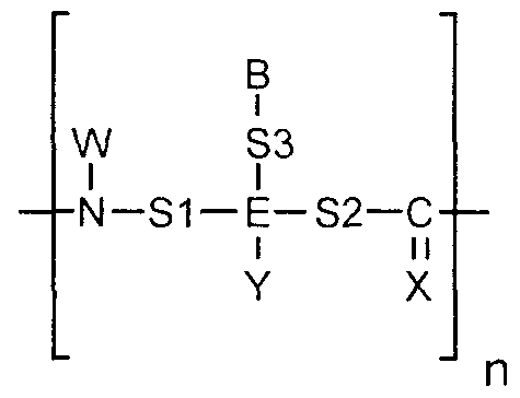
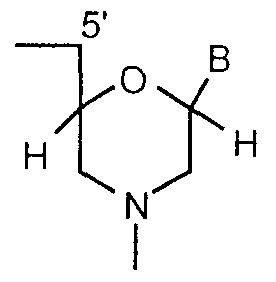
Priority Applications (3)

Application Number Priority Date Filing Date Title
AU18317/00A AU1831700A (en) 1998-12-01 1999-11-23 Methods and compositions for performing an array of chemical reactions on a support surface
JP2000585669A JP2002531470A (en) 1998-12-01 1999-11-23 Methods and compositions for performing an array of chemical reactions on a support surface
EP99961813A EP1163374A2 (en) 1998-12-01 1999-11-23 Arrays of organic compounds attached to surfaces

Applications Claiming Priority (4)

Application Number Priority Date Filing Date Title
US11052798P 1998-12-01 1998-12-01
US32647999A 1999-06-04 1999-06-04
US09/326,479 1999-06-04
US60/110,527 1999-06-04

Publications (2)

Publication Number Publication Date
WO2000033084A2 true WO2000033084A2 (en) 2000-06-08
WO2000033084A3 WO2000033084A3 (en) 2000-08-10

Family

ID=26808115

Family Applications (1)

Application Number Title Priority Date Filing Date
PCT/US1999/028021 WO2000033084A2 (en) 1998-12-01 1999-11-23 Arrays of organic compounds attached to surfaces

Country Status (4)

Country Link
EP (1) EP1163374A2 (en)
JP (1) JP2002531470A (en)
AU (1) AU1831700A (en)
WO (1) WO2000033084A2 (en)

Cited By (18)

* Cited by examiner, † Cited by third party
Publication number Priority date Publication date Assignee Title
EP1105525A1 (en) * 1999-06-07 2001-06-13 Samsung Electronics Co., Ltd. A process for preparing peptide nucleic acid probe using polymeric photoacid generator
WO2003016912A2 (en) * 2001-08-13 2003-02-27 Universität Freiburg 'lab on chip' from photoresist material for medic al diagnostic applications
EP1295846A1 (en) * 2000-06-20 2003-03-26 Kawamura Institute Of Chemical Research Microdevice having multilayer structure and method for fabricating the same
WO2003064026A1 (en) 2002-01-31 2003-08-07 Nimblegen Systems Llc Pre-patterned substrate, device and method for optical synthesis of dna probes
US6692914B1 (en) 1999-07-02 2004-02-17 Symyx Technologies, Inc. Polymer brushes for immobilizing molecules to a surface or substrate, where the polymers have water-soluble or water-dispersible segments and probes bonded thereto
EP1557717A1 (en) * 2003-12-22 2005-07-27 STMicroelectronics Limited Sensors comprising barriers of photoresist material
EP1575990A2 (en) * 2002-09-08 2005-09-21 Applera Corporation Methods, compositions and libraries pertaining pna dimer and pna oligomer synthesis
JP2005535909A (en) * 2002-08-16 2005-11-24 ディシジョン バイオマーカーズ インコーポレイテッド Substrates for material separation, reaction, and microscopic analysis
US7205161B2 (en) 2001-01-10 2007-04-17 Symyx Technologies, Inc. Polymer brushes for immobilizing molecules to a surface or substrate having improved stability
GB2409454B (en) * 2002-10-01 2007-05-23 Nimblegen Systems Inc Microarrays having multiple oligonucleotides in single array features
WO2010084196A1 (en) 2009-01-26 2010-07-29 Tethis S.R.L. Functionalized microfluidic device for immunofluorescence
CN109900687A (en) * 2019-03-04 2019-06-18 青岛大学 A kind of plant dyeing and weaving object and chemical dye fabric bleaching method for quick identification
CN109991214A (en) * 2019-03-04 2019-07-09 青岛大学 A kind of plant yarn dyeing line and chemical yarn dyeing line bleach method for quick identification
CN112453389A (en) * 2020-10-31 2021-03-09 湖北小蚂蚁金刚石工具有限公司 Device for coating diamond
US10953379B2 (en) 2004-01-07 2021-03-23 Illumina Cambridge Limited Methods and compositions of localizing nucleic acids to arrays
US20210190675A1 (en) * 2019-12-20 2021-06-24 Illumina, Inc. Flow cells
WO2024006797A1 (en) * 2022-06-29 2024-01-04 10X Genomics, Inc. Methods and compositions for refining feature boundaries in molecular arrays
WO2024006798A1 (en) * 2022-06-29 2024-01-04 10X Genomics, Inc. High definition molecular array feature generation using photoresist

Families Citing this family (3)

* Cited by examiner, † Cited by third party
Publication number Priority date Publication date Assignee Title
WO2007098914A1 (en) * 2006-03-01 2007-09-07 Roche Diagnostics Gmbh Substrate for nucleic acid amplification
JP2011017798A (en) * 2009-07-07 2011-01-27 Jsr Corp Acid-transfer resin composition, production method of biochip, and biochip
KR102563060B1 (en) * 2019-01-15 2023-08-03 동우 화인켐 주식회사 A quantum dot, a quantum dot light-emitting diode and a quantum dot film and a light converting resin composition comprising the quantum dot, a color filter and a light converting laminated base material manufactured by the composition and a display device comprising the same

Citations (6)

* Cited by examiner, † Cited by third party
Publication number Priority date Publication date Assignee Title
WO1990005910A1 (en) * 1988-11-14 1990-05-31 I Stat Corp Wholly microfabricated biosensors and process for the manufacture and use thereof
US5037720A (en) * 1987-07-21 1991-08-06 Hoechst Celanese Corporation Hydroxylated aromatic polyamide polymer containing bound naphthoquinone diazide photosensitizer, method of making and use
US5143854A (en) * 1989-06-07 1992-09-01 Affymax Technologies N.V. Large scale photolithographic solid phase synthesis of polypeptides and receptor binding screening thereof
US5736257A (en) * 1995-04-25 1998-04-07 Us Navy Photoactivatable polymers for producing patterned biomolecular assemblies
US5744305A (en) * 1989-06-07 1998-04-28 Affymetrix, Inc. Arrays of materials attached to a substrate
US5780232A (en) * 1996-05-28 1998-07-14 Atom Sciences, Inc. DNA sequencing, mapping, and diagnostic processes using hybridization and stable isotope labels of DNA

Patent Citations (6)

* Cited by examiner, † Cited by third party
Publication number Priority date Publication date Assignee Title
US5037720A (en) * 1987-07-21 1991-08-06 Hoechst Celanese Corporation Hydroxylated aromatic polyamide polymer containing bound naphthoquinone diazide photosensitizer, method of making and use
WO1990005910A1 (en) * 1988-11-14 1990-05-31 I Stat Corp Wholly microfabricated biosensors and process for the manufacture and use thereof
US5143854A (en) * 1989-06-07 1992-09-01 Affymax Technologies N.V. Large scale photolithographic solid phase synthesis of polypeptides and receptor binding screening thereof
US5744305A (en) * 1989-06-07 1998-04-28 Affymetrix, Inc. Arrays of materials attached to a substrate
US5736257A (en) * 1995-04-25 1998-04-07 Us Navy Photoactivatable polymers for producing patterned biomolecular assemblies
US5780232A (en) * 1996-05-28 1998-07-14 Atom Sciences, Inc. DNA sequencing, mapping, and diagnostic processes using hybridization and stable isotope labels of DNA

Cited By (32)

* Cited by examiner, † Cited by third party
Publication number Priority date Publication date Assignee Title
EP1105525A1 (en) * 1999-06-07 2001-06-13 Samsung Electronics Co., Ltd. A process for preparing peptide nucleic acid probe using polymeric photoacid generator
EP1105525A4 (en) * 1999-06-07 2003-07-30 Samsung Electronics Co Ltd A process for preparing peptide nucleic acid probe using polymeric photoacid generator
US6692914B1 (en) 1999-07-02 2004-02-17 Symyx Technologies, Inc. Polymer brushes for immobilizing molecules to a surface or substrate, where the polymers have water-soluble or water-dispersible segments and probes bonded thereto
US6833276B2 (en) 1999-07-02 2004-12-21 Symyx Technologies, Inc. Polymer brushes for immobilizing molecules to a surface and having water-soluble or water-dispersible segments therein and probes bonded thereto
EP1295846A4 (en) * 2000-06-20 2006-09-06 Kawamura Inst Chem Res Microdevice having multilayer structure and method for fabricating the same
KR100739515B1 (en) 2000-06-20 2007-07-13 자이단호진 가와무라 리카가쿠 겐큐쇼 Microdevice having multilayer structure and method for fabricating the same
EP1295846A1 (en) * 2000-06-20 2003-03-26 Kawamura Institute Of Chemical Research Microdevice having multilayer structure and method for fabricating the same
US7220334B2 (en) 2000-06-20 2007-05-22 Kawamura Institute Of Chemical Research Method of manufacturing microdevice having laminated structure
US7205161B2 (en) 2001-01-10 2007-04-17 Symyx Technologies, Inc. Polymer brushes for immobilizing molecules to a surface or substrate having improved stability
US7691623B2 (en) 2001-08-13 2010-04-06 Isabella Moser Method for the fabrication of a “lab on chip” from photoresist material for medical diagnostic applications
WO2003016912A2 (en) * 2001-08-13 2003-02-27 Universität Freiburg 'lab on chip' from photoresist material for medic al diagnostic applications
WO2003016912A3 (en) * 2001-08-13 2003-10-30 Univ Freiburg 'lab on chip' from photoresist material for medic al diagnostic applications
JP2006501807A (en) * 2002-01-31 2006-01-19 ニンブルゲン システムズ リミテッド ライアビリティ カンパニー Pre-patterned substrate, apparatus and method for optical synthesis of DNA probes
WO2003064026A1 (en) 2002-01-31 2003-08-07 Nimblegen Systems Llc Pre-patterned substrate, device and method for optical synthesis of dna probes
JP2005535909A (en) * 2002-08-16 2005-11-24 ディシジョン バイオマーカーズ インコーポレイテッド Substrates for material separation, reaction, and microscopic analysis
EP1575990A4 (en) * 2002-09-08 2007-04-18 Applera Corp Methods, compositions and libraries pertaining pna dimer and pna oligomer synthesis
EP1575990A2 (en) * 2002-09-08 2005-09-21 Applera Corporation Methods, compositions and libraries pertaining pna dimer and pna oligomer synthesis
GB2409454B (en) * 2002-10-01 2007-05-23 Nimblegen Systems Inc Microarrays having multiple oligonucleotides in single array features
EP1557717A1 (en) * 2003-12-22 2005-07-27 STMicroelectronics Limited Sensors comprising barriers of photoresist material
US7273633B2 (en) 2003-12-22 2007-09-25 Stmicroelectronics Ltd. Sensors
US10953379B2 (en) 2004-01-07 2021-03-23 Illumina Cambridge Limited Methods and compositions of localizing nucleic acids to arrays
US11654411B2 (en) 2004-01-07 2023-05-23 Illumina Cambridge Limited Methods and compositions of localizing nucleic acids to arrays
WO2010084196A1 (en) 2009-01-26 2010-07-29 Tethis S.R.L. Functionalized microfluidic device for immunofluorescence
WO2010083852A1 (en) * 2009-01-26 2010-07-29 Tethis S.R.L. Functionalized microfluidic device for immunofluorescence
CN109900687A (en) * 2019-03-04 2019-06-18 青岛大学 A kind of plant dyeing and weaving object and chemical dye fabric bleaching method for quick identification
CN109991214B (en) * 2019-03-04 2022-02-22 青岛大学 Quick identification method for bleaching of plant-dyed yarns and chemical-dyed yarns
CN109991214A (en) * 2019-03-04 2019-07-09 青岛大学 A kind of plant yarn dyeing line and chemical yarn dyeing line bleach method for quick identification
US20210190675A1 (en) * 2019-12-20 2021-06-24 Illumina, Inc. Flow cells
CN112453389A (en) * 2020-10-31 2021-03-09 湖北小蚂蚁金刚石工具有限公司 Device for coating diamond
CN112453389B (en) * 2020-10-31 2023-01-13 湖北小蚂蚁金刚石工具有限公司 Device for coating diamond
WO2024006797A1 (en) * 2022-06-29 2024-01-04 10X Genomics, Inc. Methods and compositions for refining feature boundaries in molecular arrays
WO2024006798A1 (en) * 2022-06-29 2024-01-04 10X Genomics, Inc. High definition molecular array feature generation using photoresist

Also Published As

Publication number Publication date
EP1163374A2 (en) 2001-12-19
JP2002531470A (en) 2002-09-24
AU1831700A (en) 2000-06-19
WO2000033084A3 (en) 2000-08-10

Similar Documents

Publication Publication Date Title
US6951682B1 (en) Porous coatings bearing ligand arrays and use thereof
WO2000033084A2 (en) Arrays of organic compounds attached to surfaces
US5405783A (en) Large scale photolithographic solid phase synthesis of an array of polymers
US6406844B1 (en) Very large scale immobilized polymer synthesis
US6589726B1 (en) Method and apparatus for in situ synthesis on a solid support
EP1147222B1 (en) Replicable probe array
US6159681A (en) Light-mediated method and apparatus for the regional analysis of biologic material
US5412087A (en) Spatially-addressable immobilization of oligonucleotides and other biological polymers on surfaces
US20050064494A1 (en) Chemically modified biological molecules and methods for coupling biological molecules to solid support
JP2006227017A (en) Method for reducing non-specific binding to nucleic acid probe array
JP2004177415A (en) Array manufacturing method
WO1999051770A1 (en) A method for the preparation of compound micro array chips and the compound micro array chips produced according to said method
WO1999061653A2 (en) Light-mediated regional analysis of biologic material
JP2004510147A (en) High density array
JP4532854B2 (en) Detection element and method of manufacturing detection element

Legal Events

Date Code Title Description
ENP Entry into the national phase in:

Ref country code: AU

Ref document number: 2000 18317

Kind code of ref document: A

Format of ref document f/p: F

AK Designated states

Kind code of ref document: A2

Designated state(s): AE AL AM AT AU AZ BA BB BG BR BY CA CH CN CR CU CZ DE DK DM EE ES FI GB GD GE GH GM HR HU ID IL IN IS JP KE KG KP KR KZ LC LK LR LS LT LU LV MA MD MG MK MN MW MX NO NZ PL PT RO RU SD SE SG SI SK SL TJ TM TR TT TZ UA UG US UZ VN YU ZA ZW

AL Designated countries for regional patents

Kind code of ref document: A2

Designated state(s): GH GM KE LS MW SD SL SZ TZ UG ZW AM AZ BY KG KZ MD RU TJ TM AT BE CH CY DE DK ES FI FR GB GR IE IT LU MC NL PT SE BF BJ CF CG CI CM GA GN GW ML MR NE SN TD TG

121 Ep: the epo has been informed by wipo that ep was designated in this application
AK Designated states

Kind code of ref document: A3

Designated state(s): AE AL AM AT AU AZ BA BB BG BR BY CA CH CN CR CU CZ DE DK DM EE ES FI GB GD GE GH GM HR HU ID IL IN IS JP KE KG KP KR KZ LC LK LR LS LT LU LV MA MD MG MK MN MW MX NO NZ PL PT RO RU SD SE SG SI SK SL TJ TM TR TT TZ UA UG US UZ VN YU ZA ZW

AL Designated countries for regional patents

Kind code of ref document: A3

Designated state(s): GH GM KE LS MW SD SL SZ TZ UG ZW AM AZ BY KG KZ MD RU TJ TM AT BE CH CY DE DK ES FI FR GB GR IE IT LU MC NL PT SE BF BJ CF CG CI CM GA GN GW ML MR NE SN TD TG

DFPE Request for preliminary examination filed prior to expiration of 19th month from priority date (pct application filed before 20040101)
ENP Entry into the national phase in:

Ref country code: JP

Ref document number: 2000 585669

Kind code of ref document: A

Format of ref document f/p: F

WWE Wipo information: entry into national phase

Ref document number: 1999961813

Country of ref document: EP

REG Reference to national code

Ref country code: DE

Ref legal event code: 8642

WWP Wipo information: published in national office

Ref document number: 1999961813

Country of ref document: EP

WWW Wipo information: withdrawn in national office

Ref document number: 1999961813

Country of ref document: EP