WO2001046710A2 - Vehicle tracking, communication and fleet management system - Google Patents
Vehicle tracking, communication and fleet management system Download PDFInfo
- Publication number
- WO2001046710A2 WO2001046710A2 PCT/US2000/033272 US0033272W WO0146710A2 WO 2001046710 A2 WO2001046710 A2 WO 2001046710A2 US 0033272 W US0033272 W US 0033272W WO 0146710 A2 WO0146710 A2 WO 0146710A2
- Authority
- WO
- WIPO (PCT)
- Prior art keywords
- data
- network
- ofthe
- vehicle
- tracker
- Prior art date
Links
Classifications
-
- B—PERFORMING OPERATIONS; TRANSPORTING
- B60—VEHICLES IN GENERAL
- B60P—VEHICLES ADAPTED FOR LOAD TRANSPORTATION OR TO TRANSPORT, TO CARRY, OR TO COMPRISE SPECIAL LOADS OR OBJECTS
- B60P3/00—Vehicles adapted to transport, to carry or to comprise special loads or objects
- B60P3/03—Vehicles adapted to transport, to carry or to comprise special loads or objects for transporting money or other valuables
-
- B—PERFORMING OPERATIONS; TRANSPORTING
- B28—WORKING CEMENT, CLAY, OR STONE
- B28C—PREPARING CLAY; PRODUCING MIXTURES CONTAINING CLAY OR CEMENTITIOUS MATERIAL, e.g. PLASTER
- B28C5/00—Apparatus or methods for producing mixtures of cement with other substances, e.g. slurries, mortars, porous or fibrous compositions
- B28C5/42—Apparatus specially adapted for being mounted on vehicles with provision for mixing during transport
- B28C5/4203—Details; Accessories
- B28C5/4206—Control apparatus; Drive systems, e.g. coupled to the vehicle drive-system
- B28C5/422—Controlling or measuring devices
-
- B—PERFORMING OPERATIONS; TRANSPORTING
- B28—WORKING CEMENT, CLAY, OR STONE
- B28C—PREPARING CLAY; PRODUCING MIXTURES CONTAINING CLAY OR CEMENTITIOUS MATERIAL, e.g. PLASTER
- B28C7/00—Controlling the operation of apparatus for producing mixtures of clay or cement with other substances; Supplying or proportioning the ingredients for mixing clay or cement with other substances; Discharging the mixture
- B28C7/02—Controlling the operation of the mixing
- B28C7/028—Controlling the operation of the mixing by counting the number of revolutions performed, or by measuring the mixing time
-
- B—PERFORMING OPERATIONS; TRANSPORTING
- B28—WORKING CEMENT, CLAY, OR STONE
- B28C—PREPARING CLAY; PRODUCING MIXTURES CONTAINING CLAY OR CEMENTITIOUS MATERIAL, e.g. PLASTER
- B28C9/00—General arrangement or layout of plant
-
- G—PHYSICS
- G01—MEASURING; TESTING
- G01M—TESTING STATIC OR DYNAMIC BALANCE OF MACHINES OR STRUCTURES; TESTING OF STRUCTURES OR APPARATUS, NOT OTHERWISE PROVIDED FOR
- G01M17/00—Testing of vehicles
-
- G—PHYSICS
- G07—CHECKING-DEVICES
- G07C—TIME OR ATTENDANCE REGISTERS; REGISTERING OR INDICATING THE WORKING OF MACHINES; GENERATING RANDOM NUMBERS; VOTING OR LOTTERY APPARATUS; ARRANGEMENTS, SYSTEMS OR APPARATUS FOR CHECKING NOT PROVIDED FOR ELSEWHERE
- G07C5/00—Registering or indicating the working of vehicles
- G07C5/008—Registering or indicating the working of vehicles communicating information to a remotely located station
-
- G—PHYSICS
- G08—SIGNALLING
- G08G—TRAFFIC CONTROL SYSTEMS
- G08G1/00—Traffic control systems for road vehicles
- G08G1/20—Monitoring the location of vehicles belonging to a group, e.g. fleet of vehicles, countable or determined number of vehicles
-
- H—ELECTRICITY
- H04—ELECTRIC COMMUNICATION TECHNIQUE
- H04W—WIRELESS COMMUNICATION NETWORKS
- H04W56/00—Synchronisation arrangements
- H04W56/0055—Synchronisation arrangements determining timing error of reception due to propagation delay
- H04W56/0065—Synchronisation arrangements determining timing error of reception due to propagation delay using measurement of signal travel time
- H04W56/007—Open loop measurement
- H04W56/0075—Open loop measurement based on arrival time vs. expected arrival time
- H04W56/0085—Open loop measurement based on arrival time vs. expected arrival time detecting a given structure in the signal
-
- H—ELECTRICITY
- H04—ELECTRIC COMMUNICATION TECHNIQUE
- H04W—WIRELESS COMMUNICATION NETWORKS
- H04W16/00—Network planning, e.g. coverage or traffic planning tools; Network deployment, e.g. resource partitioning or cells structures
- H04W16/14—Spectrum sharing arrangements between different networks
-
- H—ELECTRICITY
- H04—ELECTRIC COMMUNICATION TECHNIQUE
- H04W—WIRELESS COMMUNICATION NETWORKS
- H04W28/00—Network traffic management; Network resource management
- H04W28/16—Central resource management; Negotiation of resources or communication parameters, e.g. negotiating bandwidth or QoS [Quality of Service]
- H04W28/18—Negotiating wireless communication parameters
- H04W28/22—Negotiating communication rate
-
- H—ELECTRICITY
- H04—ELECTRIC COMMUNICATION TECHNIQUE
- H04W—WIRELESS COMMUNICATION NETWORKS
- H04W64/00—Locating users or terminals or network equipment for network management purposes, e.g. mobility management
-
- H—ELECTRICITY
- H04—ELECTRIC COMMUNICATION TECHNIQUE
- H04W—WIRELESS COMMUNICATION NETWORKS
- H04W72/00—Local resource management
- H04W72/50—Allocation or scheduling criteria for wireless resources
- H04W72/56—Allocation or scheduling criteria for wireless resources based on priority criteria
-
- H—ELECTRICITY
- H04—ELECTRIC COMMUNICATION TECHNIQUE
- H04W—WIRELESS COMMUNICATION NETWORKS
- H04W74/00—Wireless channel access, e.g. scheduled or random access
- H04W74/04—Scheduled or contention-free access
-
- H—ELECTRICITY
- H04—ELECTRIC COMMUNICATION TECHNIQUE
- H04W—WIRELESS COMMUNICATION NETWORKS
- H04W8/00—Network data management
- H04W8/22—Processing or transfer of terminal data, e.g. status or physical capabilities
- H04W8/24—Transfer of terminal data
- H04W8/245—Transfer of terminal data from a network towards a terminal
-
- H—ELECTRICITY
- H04—ELECTRIC COMMUNICATION TECHNIQUE
- H04W—WIRELESS COMMUNICATION NETWORKS
- H04W84/00—Network topologies
Definitions
- the invention disclosed herein broadly relates to asset management systems, and more particularly to a system for tracking the real-time location and status of vehicles of a fleet, and for communicating between the vehicles and a dispatcher or expediter in the fleet offices.
- GPS Global Positioning System
- DGPS differential GPS
- an alternative navigation system such as dead reckoning (DR) navigation may be used to provide vehicle position and velocity data in urban canyons (i.e., streets bordered by tall buildings) where GPS measurements are only intermittently available.
- a map matching technique or navigation grid may be used as another or additional alternative.
- wireless voice communication between dispatchers and drivers is the primary means of addressing the need ofthe fleet owner or operator to know what each vehicle is doing, i.e., its operations talcing place at any given time, and where the vehicle is located when a particular operation is occurring.
- status boxes have recently come into use. The status boxes require the driver to press a button at each stage of operation such as "load,” leave plant,” “arrive job,” “begin pour,” and so forth.
- Time Division Multiple Access (TDMA) wireless networks which are in use for many applications including digital cellular telephones and wireless local area networks, may be used for the communication between dispatchers and drivers.
- a TDMA network allows multiple users of a single channel or frequency by assigning specific time slots to each user to use exclusively for transmission.
- precise time synchronization between members ofthe network is required.
- Efficient use of bandwidth in the network requires that the gap times between transmissions of each user, which is wasted time, be mii ⁇ nized.
- An important component to the gap time is uncertainty of time in all the participants in the network. Synchronization of wireless networks is often very coarse, requiring large gaps between transmissions, if specialized hardware is not used.
- synchronization of network elements to a precise reference like GPS based timing information involves having a GPS receiver located on each network element, both mobile and fixed, increasing installation costs and complexity for both fixed network infrastructure and mobile network devices, especially if navigation data provided by GPS is not required.
- Precise time synchronization between all ofthe wireless devices in the network can be performed in a number of ways.
- a precise, stable time reference such as one based on the Global Positioning System (GPS) or other time distribution services, is located within each wireless device or within just the fixed infrastructure ofthe network, with synchronization information being transmitted to the mobile units.
- GPS Global Positioning System
- device or infrastructure costs are increased because timing equipment has to be distributed among several locations or devices and installed where space and access for maintenance are limited.
- Transmitting as much information as possible in a given amount of bandwidth is an important design goal in any communications network. This is especially true in wireless networks in which available bandwidth is very limited and customer requirements for data throughput are immense. Operation on most wireless bands is subject to occupied bandwidth constraints, requiring the data signal to be contained in a vary narrow region of the electromagnetic spectrum. In TDMA networks, a challenge is to minimize the gap times between transmissions and the overhead associated with each data packet in order to send as much information bearing data over the network as continuously as possible.
- the present invention addresses these two requirements with digital filtering to control occupied bandwidth and data recovery by the receiving system that requires no synchronization patterns to be transmitted.
- the fleet management system (sometimes hereinafter called the PROTRAK system or the Galileo system (each of PROTRAK and Galileo, either alone or with various suffixes attached, is a trademark of Fleet Management Services, Inc. of Chandler, Arizona, to which the present patent application is assigned), the fleet management system, or simply the system) is to provide fleet management information to customers (i.e., the owners, operators, subscribers, or users ofthe fleet who seek to avail themselves ofthe advantages of a vehicle tracking, communication and fleet management system) to enable them to manage their assets more profitably.
- the system provides its customers with several means to accomplish this.
- the PROTRAK system gives the fleet operator the capability to locate vehicles of the fleet in real-time.
- the system allows the operator to communicate with those vehicles over a very efficient and reliable wireless network — a time division multiple access (TDMA) wireless network.
- TDMA time division multiple access
- the system enables the operator to receive timely, accurate data regarding what each vehicle ofthe fleet is doing, i.e., what operations) it is perforaiing at any given time.
- the system provides the operator with an ability to correlate the position and messaging information generated by the system with the operator's other management information systems to provide an integrated information source for improved fleet business management.
- a fleet operator's existing management systems typically consist of accounting, human resources, inventory, and other systems which may not be well integrated.
- the operator may not have a reliable way to measure vehicle and driver performance which is critical to the operator's operations.
- the PROTRAK system provides the required vehicle and driver information together with a database management system that is capable of collecting such information and integrating it with data retrieved from the operator's other information systems in a database management application. This application can be used by the operator to generate reports that are tailored to its business and are based on all ofthe available data.
- the PROTRAK system is particularly designed to operate in a market niche between cellular, specialized mobile radio (SMR), and paging services.
- SMR specialized mobile radio
- the system may be used to track virtually any number of vehicles in a fleet across all metropolitan areas covered by the network.
- Timely, accurate data can be made available to the fleet operator automatically by combining wireless data network technology, a wireless data computer (also referred to herein as a tracking computer, or simply a tracker), sensors, and dispatch and/or database reporting software and computers at the fleet operator's facilities to receive, display, and process the data provided by the vehicles.
- the vehicle computer has interfaces to various sensors that indicate operations being performed by the vehicle. Data provided by the sensors are processed by software algorithms in the computer to determine when events of interest occur. The event, relevant parameters, and the time ofthe event are then immediately transmitted through the wireless network to the fleet operator.
- the network used to enable event driven status reporting is designed to provide frequent small packets of data from vehicles to fleet owners very efficiently.
- the network architecture is a unique, full duplex design for metropolitan area operations.
- Data are transmitted to vehicles over a subcarrier on an FM radio station.
- Vehicles transmit their data using a TDMA protocol on a single UHF channel.
- Vehicle data are received by Network Hubs, which are receivers placed on commercial towers around the metropolitan area of interest.
- the received data are sent back to a Network Distribution Center (NDC, occasionally referred to herein as Network Control Center) via telephone lines and are relayed to the fleet owners via the Internet, telephone connection, or other preferably wireless means.
- NDC Network Distribution Center
- Data sent to the vehicles by the owners is first sent to the NDC which sends it to transmitting equipment at the radio station via telephone lines.
- the TDMA protocol in the network is controlled by servers in the NDC.
- the precise timing required by the TDMA network for efficient operation is controlled by a synchronization pattern contained in the subcarrier data broadcast that is received by the vehicles and the network hubs within the PROTRAK system.
- This enables all vehicles and hubs to have a common time reference that is accurate to about three microseconds.
- This enables a multiplicity of (e.g., 50) vehicle reports in the TDMA network each second.
- the servers assign reporting intervals and time slots to vehicles so that they can send data and status changes automatically. Typical periodic updates of navigation data or other non-critical information are provided at two to three minute intervals; it is impractical for the vehicle computer (tracker) to wait for a periodic interval of that length to send time critical event data.
- a total of 5020-msec long time slots are available for periodic transmissions. Multiple vehicles share slots, the number depending upon the update rate ofthe slot. For example, 60 vehicles can share a one minute update interval slot. Slots not assigned to periodic updates are open for any vehicle to use to request access to the network. If more than one vehicle tries to use the same interval in a particular slot, both may still be heard if each is heard by a separate hub receive site. Otherwise there is a colUsion (interference) of data, and the vehicles involved must retry their requests.
- colUsion interference
- a method and apparatus for automatically determining and reporting events from a vehicle to an owner or dispatcher of the vehicle at a remote location.
- Events to be reported are changes in status of vehicle operation, location, or measurements of vehicle systems or cargo.
- a computer tilt computer, generally referred to herein as the tracker
- Computers at a fixed location display these status changes for use by the dispatcher or record the data for later analysis.
- the tracking computer has navigation hardware and software for deterniining the location, speed, and direction of travel ofthe vehicle in which it is instaUed.
- the appUcation software used by operators to receive data from their vehicles also enables them to send "site dispatch" commands to the trackers which indicates a rectangular region to be used to indicate where events such as "load,” or "unload,” for example, should take place.
- Location information is then combined with the sensor data in the algorithms to determine event sequencing, provide exception reporting to indicate that the vehicle performed a specific action at the wrong location, performed unauthorized stops on the way to or from a job, or other events specific to a particular business or industry.
- three basic components are combined to enable vehicle data to be useful to the fleet operator, namely: (1) sensors on the vehicle to measure parameters to be combined in a computer to automatically determine when events of interest occur, (2) a wireless network that allows prompt, economical transmission of smaU packets of data containing event status to the fleet operator, and (3) software appUcations to store and further process event information for improved asset management by the fleet operator.
- the tracker has several inputs and outputs to aUow it to sense and control numerous vehicle functions simultaneously, with configurable interfaces that include serial interfaces, analog inputs, discrete inputs, discrete outputs, and an interface for pulse measurement or clock outputs.
- the tracker also has dedicated interfaces for measuring battery voltage, ignition, speed, and reverse. These enable measurement of a wide variety of vehicle functions, either directly or through auxiUary sensor modules that provide data to the computer serial interfaces.
- the outputs allow control of vehicle functions remotely, through the wireless network. Tracker software permits processing and integration of various sensor inputs to enable higher level or abstract status events to be determined and reported.
- a loading is determined from a number of inputs by combining truck location at the plant, truck stationary, and truck drum rotating in the charge direction at a speed greater than a predetermined n-storymum speed for a niinimum time interval.
- status events include "ambulance emergency
- the tracker reports events over the wireless network whose architecture and protocols are tailored for prompt reporting of events while concurrently supporting slower, periodic update intervals for less critical data.
- the network uses a TDMA protocol to enable a large number of vehicles to send short data packets frequently on a single wireless channel. Data is sent to the vehicles over a subcarrier on an FM broadcast channel.
- An important aspect ofthe invention is the provision of precise time synchronization required for the TDMA protocol over the FM Unk to the vehicles and receive sites. In the exemplary embodiment, as many as fifty vehicles per second can report data at a variety of update intervals ranging between five seconds and one hour.
- Typical periodic updates of navigation data and other non-critical information are provided at two to three minute intervals. However, it is not practical for the tracker to wait for periodic intervals of that length to send time critical event data. Accordingly, for such events, the network maintains a number of time slots for additional access to the network on request of any vehicle needing to transmit event data. The requesting vehicle is then granted sufficient auxuiary reporting times at twelve second intervals to send its data. The total latency between an event being detected and the transmission of data is kept under thirty seconds.
- Owners and dispatchers of fleet vehicles are provided with computer software appUcations that enable connection of their desktop PC's to the TDMA network using the
- Data furnished from the vehicles are routed to these appUcations by the network servers, and are also stored in a local database.
- One of these software applications allows viewing the vehicle locations as icons on a map displayed on a monitor, showing event changes for each vehicle on the map in real time as they occur, and also enables the dispatcher to send messages or dispatch locations to the vehicles.
- Automated events may be provided as weU to other dispatch or vehicle management appUcations, as required.
- these applications integrate vehicle event data with other systems utilized in the fleet operator's business, such as order entry and caU management. Reports on vehicle events may be generated from these appUcations over the Internet from data stored in the network database.
- the present invention minimizes infrastructure cost for time references in the TDMA wireless network and locates the time reference in a central network control faculty that is easily maintained and monitored.
- the time reference uses GPS referenced time, and TDMA network time is held in synchronization to the GPS reference by a wireless phase lock loop (PLL), removing the requirement to locate the time reference within the wireless transceiver devices or infrastructure elements.
- PLL wireless phase lock loop
- This aspect ofthe invention enables precise time synchronization of aU wireless network elements by using special timing hardware and by distributing a single, remote GPS based time reference throughout the network using a wireless PLL.
- Digital data is remotely synchronized in the TDMA network, a fuU duplex system designed to efficiently transmit short bursts of data from mobile vehicles to their owner on a frequent basis.
- Vehicles transmit data using a TDMA protocol in the UHF frequency band in precisely controlled time slots at a rate of 50 vehicles per second. Vehicles send location, status, and message data to the fleet owners or dispatchers who are connected to the wireless network through the Internet or other means.
- Data transmitted to the vehicles is broadcast over a subcarrier of an FM radio station, including network timing and control information as well and messages and information from fleet operators.
- Timing ofthe TDMA portion ofthe network is controUed from a central network control faciUty that houses the servers which control vehicle access to the network and manage fleet owner connections to the network. Synchronization ofthe vehicle devices and fixed hub receiver systems that receive vehicle data is maintained through synchronization information contained in the FM subcarrier broadcast. The FM subcarrier timing data is, in turn, referenced to a GPS based time source at the network control center.
- a Subcarrier Control Computer responsible for providing the data to the subcarrier modulator, is located at the FM radio station transmitter or studio facilities. It clocks the transmit data at precise intervals based on timing commands from a Network Timing Control Computer (NTCC), located at the network control center.
- NTCC Network Timing Control Computer
- the NTCC and SCC are connected through a modem for data and timing control commands sent to the SCC.
- the NTCC computes timing commands based on the synchronization information from a GPS receiver time reference and that from an FM subcarrier receiver which receives data from the SCC.
- the difference in time from the GPS time reference and the received synchronization data over the FM subcarrier is processed by the NTCC using a PLL algorithm to generate a timing correction which is sent to the SCC.
- This wireless PLL timing control loop enables a single, remotely located time reference to synchronize the TDMA network.
- the feedback inherent in the control loop aUows the system to compensate for variations in FM radio station group delay so that the broadcast synchronization data is apphcable at the FM antenna. This is important for large networks based on this technology that require multiple FM stations to cover overlapping geographical areas, because it enables the FM stations to be synchronized.
- the invention also relates to bandwidth optimizations for the transmission of data over wireless TDMA data networks. The invention minimizes occupied bandwidth in a wireless channel by digitaUy filtering the data to be transmitted before modulation.
- the filter is implemented in a low-cost microcontroller, which replaces each edge in a digital square wave data stream with transitions that have the shapes of rising or falling sine waves. This has the advantages of reducing higher harmonics in the data signal, especially at the highest data rate, where the square wave is effectively replaced by a sine wave.
- Another aspect ofthe invention maximizes the efficiency ofthe TDMA network by refraining from sending any special bit synchronization information in addition to the data. In most systems, a large number of bits is devoted to synchronization, framing, or data clock recovery.
- the bit clock and data synchronization are performed by the receiver by using forward error correction algorithms, special bit interleaving, and high performance digital signal processing hardware and software.
- Still another aspect ofthe invention uses space diversity combining between multiple receive sites to improve the reUabiUty of receiving data. More reUable data reception saves bandwidth by reducing the number of retries required to move data through the network.
- FIG. 1 is a simplified block diagram of the overaU PROTRAK system, including the TDMA network, ofthe invention
- FIG. 2 is a block diagram ofthe system architecture for customer appUcation interfaces
- FIG. 3 is a detailed schematic diagram of the components ofthe wireless network and customer interfaces
- FIG. 4 iUustrates details ofthe NDC in the network of FIG. 3;
- FIG. 5 is a time-line of data flow in the network;
- FIG. 6 is a block diagram ofthe base message feedback loop for bit-sync timing
- FIG. 7 is a diagram ofthe base message broadcast format
- FIG. 8 is a diagram of an exemplary tracker module message transmit frame
- FIG. 9 is a diagram illustrating the repeating interval relationship to slots, frames and frame cycles for tracker message packets
- FIG. 10 iUustrates the relationship between trackers, slots, and repeating intervals
- FIG. 11 is a diagram of a nominal navigation grid used in the system ofthe invention.
- FIG. 12 is a diagram of a timing control phase locked loop (PLL) according to an aspect ofthe invention for the TDMA network of FIG. 1;
- PLL phase locked loop
- FIG. 13 is a timing diagram ofthe synchronization pulse sequence transmitted by the SCC on the FM subcarrier at the start of each second's data, for the control loop of FIG. 12;
- FIGS. 14A-D are flow charts of timing control loop processing performed in operational modes ofthe NTCC software synchronization ofthe TDMA network to GPS time;
- FIG. 15 is a block diagram (mathematical) ofthe timing control loop
- FIG. 16 is a block diagram ofthe transmit TDMA data processing performed by the tracking computer (tracker) installed in a fleet vehicle;
- FIG. 17 is a table nlustrating the TDMA transmit data interleaving pattern;
- FIGS. 18A-C are diagrams comparing an original TDMA data sequence to the delay coded version of that sequence, and also iUustrating premodulation filtering ofthe delay coded sequence;
- FIG. 19 is a flow chart ofthe filtering algorithm performed by a speciaUy selected microcontroUer which implements premodulation filtering for the result shown in FIG. 18C;
- FIG. 20 is a diagram representing a comparison ofthe approximate relative power spectrums ofthe unencoded, delay coded, and filtered data of FIGS. 18A-C;
- FIG. 21 is a block diagram that iUustrates the receive TDMA data processing performed by the Network Hub receiver;
- FIG. 22 is a flow chart ofthe space diversity algorithm used by the NDC server to combine vehicle data received by the network hubs;
- FIG. 23 iUustrates an exemplary placement ofthe tracker, a Mobile Data Terminal (MDT) and antennas on a typical fleet vehicle, the vehicle being further equipped for accommodating various sensors for event reporting;
- FIG. 24 is a simplified block diagram of a tracker installed in a vehicle of FIG. 23;
- FIG. 25 is a block diagram ofthe internal power distribution to the tracker
- FIG. 26 is a block diagram of the tracker power distribution summary
- FIG. 27 is a diagram of the power mode state transition logic ofthe tracker
- FIG. 28 is a synchronization timing and data clocking diagram for the tracker and Network Hubs
- FIG. 29 is a timing diagram of tracker data transmissions
- FIG. 30 is a simplified block diagram of a Network Hub
- FIG. 31 is a simplified block diagram of a Subcarrier Control Computer (SCC);
- SCC Subcarrier Control Computer
- FIG. 32 is a diagram ofthe NTCC/SCC data flow
- FIG. 33 is a diagram iUustrating various sensors, inputs, outputs and interfaces to the tracker of FIG. 24;
- FIG. 34 is an exemplary rectangular zone on a stored map used to determine and display the tracker's location (in particular, that ofthe vehicle in which the tracker is mounted);
- FIG. 35 is a simplified block diagram of a drum rotation sensor used for a ready- mix concrete track;
- FIG. 36 is a timing diagram ofthe pulses resulting from the interaction of sensor and magnets on dram rotation, for the sensor embodiment of FIG. 35;
- FIG. 37 is a state transition diagram that defines logic used by the tracker to combine sensor and navigation data to automatically derive status of a ready-mix concrete truck.
- FIG. 38 is a flow chart of a preferred diversity algorithm used by the tracker for recovering corrupted data.
- the "brain” ofthe system is the Network Distribution Center (NDC) 10 which is responsible for interfacing with subscriber (variously also referred to herein as customer, owner, operator, fleet subscriber, or user) fleets via a modem on a public switched telephone network (PSTN) line or Internet or other wide area network, and interfacing with fleet vehicles through a multipUcity of Network Hubs (sometimes referred to herein as Net Hubs, or simply, Hubs) such as 11-1, 11-2, ... 11-i, and one or more FM Radio Stations such as 12.
- NDC Network Distribution Center
- Information to be passed to vehicles in one or more fleets of interest is generated by a fleet dispatch office terminal or customer command station (CCS) such as 14 for Customer A, 15 for Customer B, ... and 16 for Customer i, for deUvery to the vehicles such as 17-1, 17-2, ... 17-n for Customer A (and so forth for customers B, ... i).
- CCS customer command station
- the information is initially sent from the respective CCS via modem over the PSTN (e.g., Unes
- the NDC prioritizes the information and sends it via a modem over the PSTN (e.g., line 22) or over such other means to FM Radio Station 12, from which the information is broadcast, e.g., on a 67 KHz or 92 KHz FM subcarrier.
- the information is broadcast with precise timing defined by GPS satellite navigation information.
- AU vehicles in the network receive the approximately 4,664 bits per second (bps) binary frequency shift keyed (BFSK) FM subcarrier broadcast from the FM Radio Station (and others, if apphcable) and decode the information contained therein.
- bps binary frequency shift keyed
- Each vehicle is assigned a slot in time to broadcast its location and responses to CCS requests.
- the assigned slots are unique to preclude simultaneous broadcasting by two or more vehicles, and the broadcast timing is precisely controUed through GPS and FM subcarrier synchronization.
- NDC 10 parses aU received data and provides the vehicle location and status information for each specific fleet subscriber to its respective CCS over the PSTN. Real-time tracking of vehicle location and status may be performed by the
- PROTRAK system as often as once every five seconds, for example, but more generally is updated at a rate of once every three minutes.
- Vehicle locations are tracked with an accuracy to about 5 meters through the use of DGPS information provided by the FM subcarrier broadcast. Where GPS is intermittently unavailable because of signal masking when vehicles are located on city streets bordered by taU buUdings or because of other obstructions, the system employs dead reckoning (DR), map-matching and/or other navigation techniques to detect the vehicle location.
- DR dead reckoning
- the wireless system provides a versatile medium for sending brief messages consisting of short packets of information to or from a vehicle mounted instrument or other wireless communications device. Although the system is aimed at business asset management, wireless service supports a wide range of packet communication needs for fixed as well as mobile assets. Use of GPS in the receiving device is not required, by virtue of GPS synchronization ofthe FM subcarrier broadcasts.
- the system capacity is sufficient to accommodate at least 5,000 individual vehicles being tracked in the network at any one time with the bandwidth provided by a single FM radio station subcarrier at 67 KHz or 92 KHz for outbound communications and a single UHF or narrowband personal communication services (PCS) 12.5 KHz bandwidth frequency for inbound vehicle messages.
- System expansion may be provided, for example, in 5,000 vehicle blocks by the addition of another FM radio station subcarrier and another UHF or narrowband PCS frequency. Where feasible, frequency reuse principles on UHF or narrowband PCS frequencies are appUed before another inbound frequency is added, to maximize channel capacity.
- Communications in the PROTRAK system provide greater reUabiUty than ceUular or specialized mobile radio (SMR), and possibly than paging systems, with anticipated reUable reception of messages by vehicles and dispatchers 97% first time. IT information is not received the first time, the system is able to make that determination and witt re-attempt transmission until successful, or until it is found that delivery cannot be made. At least some fleet operators (e.g., ambulance services) require reUable operation despite adverse conditions, such as power outages.
- the overall system has internal backups to avoid single point faUures.
- Fleet subscriber vehicles are allowed to "roam" from one network ofthe system to another, such as where a vehicle is in transit from one metropoUtan area to another. The system enables the vehicle to gracefuUy exit the first city network and sirnilarly enter the second city network when in range ofthe second city.
- Vehicle trackers i.e., on-board tracker modules
- Network Hubs are capable of supporting various antenna and receiver configurations to enhance coverage and various power configurations to support remote site operation.
- UnavailabiUty of telephone Unes does not present a problem, since wireless means are used for indirect or direct interface to the NDC.
- PROTRAK system architecture and database management appUcations that interact with each subscriber's (customer's) existing information systems include the NDC and CCSs which are used to provide real-time vehicle location and message capabihty for dispatchers.
- the customer side ofthe PROTRAK system consists of three appUcations, including (1) a database management and CCS server (DMCS) that ties the network and customer information together, (2) the CCSs with their real-time location and messaging services, and (3) report generation that allows customers to access and manipulate the data managed by the DMCS.
- DMCS database management and CCS server
- FIG. 2 A block diagram ofthe system architecture with respect to customer appUcation interfaces is shown in FIG. 2.
- NDC 10 runs two server appUcations, namely, an NDC Server 32 that provides real-time information to connected customers, and a tracking data log server 33 that coUects tracking information from the system in real-time and stores it in a large capacity database, with additional capabihty to respond to queries for historical tracking data.
- the customer estabUshes a single conventional TCP/IP connection (34, 35) to each of these servers through a single dial-up line directly to the NDC or through the Internet (via an Internet service provider, or ISP).
- DMCS 27 The connections to the NDC are controUed by DMCS 27 which may be located at the customer's faculty 28 remote from the NDC 10. AU ofthe real-time data avaUable for all ofthe customer's vehicles are provided to this DMCS appUcation. DMCS 27 stores these data and passes them on to the CCS appUcations 30 in filtered format so that CCS operators can observe (e.g., as icons on a monitor display or screen at their respective stations) and communicate with only those vehicles for which they are responsible. Another function of DMCS 27 is to provide interfaces to a customer's other management applications such as accounting 31, human resources 32, inventory control
- DMCS 27 and CCS 30 and database reporting 36 appUcations are conventional TCP/ P. These applications may ran on the same or separate computers using, for example, Windows (trademark of Microsoft Corporation) 95, Windows 98 or Windows NT (or any advance of such software, or any software of other providers which enables the same or similar functions to be performed).
- the operator's other appUcations interface to DMCS 27 through standard or custom interface protocols.
- the DMCS appUcation is responsible for tying together the NDC server appUcations, CCS and database reporting appUcations, and the operator's existing appUcations (e.g., the customer's management information and back office systems) into an integrated system.
- the DMCS acts as the enterprise connection to NDC 10. It establishes TCP/IP socket connections to the NDC real-time and data log servers 32 and 33 as required, and maintains access to data for aU ofthe fleet operator's vehicles to be tracked by the PROTRAK system. Vehicle location and message data is provided by NDC 10, and DMCS 27 sends real-time messages and commands to the vehicles and may request archived tracking information from the NDC for time periods when the DMCS was not logged-in to the NDC.
- the CCS (or each of multiple CCSs) 30 is primarily a real-time vehicle location display and messaging tool to support dispatching functions.
- DMCS 27 routes commands and messages from CCS 30 to NDC 10, and provides tracking data from the NDC to the
- the DMCS supports multiple CCS appUcations operating simultaneously, controUing and viewing different groups of vehicles in an overaU fleet.
- DMCS 27 also supports database queries from multiple CCS 30 and database reporting 36 applications. Each CCS 30 requires real-time information from the database regarding vehicle drivers, dispatching, scheduUng, and cargo.
- the database reporting appUcation requires historical tracking data and information from other systems as necessary to produce reports pertaining to the customer's business.
- NDC software and hardware system in the simplified block diagram of FIG. 3, which emphasizes communication protocols used by the TSTDC software appUcations.
- the NDC 10 controls information flow between vehicles (e.g., 17) and their fleet subscriber command station (e.g., CCSs 14 and 15 at customer site 13) logged into the system.
- the RF network is managed by the NDC by controUing network timing, and dete ⁇ mning the nature ofthe data transmitted to the vehicles.
- AU data received by Network Hubs e.g., 11-1, 11-2) are collected by NDC 10 for processing, distribution to customers, and data archiving, and the NDC aUows customers to log in via the Internet, TCP/IP network, or other suitable connection 40.
- An interface to a PROTRAK Data Center (PDC, not shown) supports roaming between cities and overaU tracker-fleet subscriber identification.
- An NDC Server 42 in NDC 10 communicates with the CCSs 14, 15, etc., as weU as with NDC command stations (not shown) within the NDC, and Network Hubs 11-1, ... 11-i, through respective sockets and related net connections including a router and a modem, and also with a Network Tuning and Control Computer (NTCC) 47 through a serial interface 49.
- the NDC Server has only one interface — a messaging protocol which wiU be described presently.
- NDC adrninistrators use NDC Command Stations (which are similar to CCSs, but within the NDC) for display, control, analysis and maintenance ofthe NDC Server.
- NDC Server 42 is assigned a registered domain name and an IP address on the Internet to aUow fleet subscribers and/or NDC command stations to connect to the
- DMCS 27 interfaces with the customer's critical business appUcations 31, etc. including accounting, inventory control, human resources, etc., as weU as with CCSs 14, 15, etc., and NDC 10.
- NDC Server 42 controls all data sent to and received from vehicles and command stations, and also controls the configuration ofthe TDMA vehicle transmission UHF radio network by assigning vehicles to specific time slots for transmission and controlling which vehicles are allowed to operate. Data from vehicles 17 received from the Network Hubs 11-1, etc. are combined and decoded, and then provided to fleet subscriber CCSs for use in maintaining control of he radio network.
- Data from CCSs are sent to vehicles as required, and are also used to schedule the appropriate level of update service, with the data being transmitted to the vehicles over a serial interface to each NTCC computer at the NDC.
- the network control function is the most critical task of NDC server 42, performed in real-time based on prompts from NTCC 47.
- System requirements for substantial TCP/IP support, Internet, and maintenance and support workstations require use of a platform such as Windows NT, which aUows the system to make use of third party hardware and software.
- Running this task periodicaUy, once per second, is accompUshed, first, by providing the network control function with sufficient priority to complete its required tasks within the one second period aUowed; and, second, by polling the NTCC serial interface at a high rate to detect the reception of timing data indicating that the server should start the network control task.
- NTCC 47 controls the real-time portion ofthe PROTRAK system, including the SCC 48 transmit timing through a feedback loop (to be discussed presently in connection with FIG. 6) using an FM receiver in a roof module.
- OneNTCC roofmodule 55 exists for each FM radio station 12 supported by NDC 10.
- the NTCC 47 is also responsible for introducing frame ID data and differential correction data into the transmitted data stream. Data packets generated by server 42 are sent to NTCC 47 for inclusion in the output data stream.
- NTCC 47 communicates with SCC 48 via a dedicated modem 51 and telephone line or other line that is not part ofthe modem rack used for the Network Hubs and the CCSs, the time-critical interface for timing and corrections is separated from any unpredictable activities ofthe modem rack or ethernet interface.
- NTCC 47 monitors the FM station 12 broadcast for timing and content. If the broadcast was received skewed with respect to the GPS integer second, then timing correction commands are sent to SCC 48. The NTCC also compares the received broadcast data to the data block that was transmitted, to ensure the data was correct. FM received signal strength is also monitored to detect changes in FM broadcast power. Broadcast and SCC status are provided to the server 42 so that it can determine what action to take in the event of a failure.
- a number of Windows NT workstations constitute the NDC command stations (e.g., 43, 45, FIG. 4), which are connected to NDC server 42 via 100 Mbps ethernet or other suitable path such as a local area network (LAN). These stations provide the capabuity to perform several functions, including displays of different areas ofthe navigation grid, network and modem monitoring, data log analysis, user account maintenance, and software development.
- NDC command stations e.g., 43, 45, FIG. 4
- LAN local area network
- the NDC server 42 may communicate with the Network Hubs and CCSs via a TCP/ P, or by way of other connectivity options such as those shown in FIG. 4.
- a US Robotics Total Control modem rack may be used to provide TCP/TP connectivity to the server.
- Each rack is implemented to support 48 modems via 2 conventional TI lines, and several racks can be stacked to support a larger number of modems.
- the server may, for example, have two independent ethernet networks, and the modem rack is on a separate network from the NDC command stations so that NDC command station network activity wiU not introduce any latency in the modem data.
- User connections do not have any real-time requirements, but data transferred between the server 42 and the Network Hubs (e.g., 41-1, ..., 41-1) must occur regularly at one second intervals.
- a time-line ofthe network data flow is shown in FIG. 5.
- Data transmitted by the vehicles on frame 1 is available to the NDC server 42 (FIG.3) at the beginning of frame 3.
- the NDC server 42 On the detection ofthe start of frame status from the NTCC 47, that data and user data received over frame 2 are processed.
- Data packets to be transmitted to vehicles are also sent to the NTCC.
- the NTCC formulates a data block which is sent to SCC 48 during frame 4.
- the SCC finaUy broadcasts the data block on frame 5.
- the network control function comprises radio network management, vehicle and user input data processing, and base output data processing. Based on the time-line shown in FIG. 5, these tasks combined must begin promptly with the detection ofthe start of a frame (based on serial data received from the NTCC) and complete within roughly one-half second.
- NDC 10 controls the assignment of network transmit slots to the vehicles and manages the exit and entry of vehicles into and out ofthe network. It also coordinates the broadcast of network control, vehicle control, message, and system identification packets to the vehicles. Network management in the system must run at one second intervals and complete within about one-half second. The system maintains data stractures for all active vehicles and fleet subscriber command stations, and has a capability to cross-reference vehicles to fleets and to assigned broadcast slots.
- Data required includes: • vehicle position for transmission to fleet subscribers, and for data logging; position data may also be used for UHF frequency reuse or FM channel assignment; the transmit slot(s) occupied by the vehicle; the vehicle's tracker ID, local control ID, owner, and group; message and control acknowledges, retries, and time-outs; • roaming information; and service type, including nominal update rates, real-time service or track history requirements.
- the NDC server requires efficient and logical algorithms to assign vehicles to the transmit slots.
- NDC 10 processes the network data in one second intervals, and therefore, the vehicle data from each Hub must be avaUable for processing by the NDC server during the one second interval after that frame's data was received by the Hubs.
- the server 42 performs space diversity processing, error control decoding and error correction, and decryption on the received vehicle data packets.
- Data received in time slots assigned to vehicles may be avaUable from multiple Hubs. Since only one vehicle 17 has been transmitting, the received data at each Hub should be the same.
- NDC 10 can then blend the data from all Hubs to produce a most likely solution.
- vehicle data packets are coded to aUow numerous bit errors to be corrected through interleaving ofthe data bits and forward error correction coding.
- the data packets are then decrypted.
- the received data packets are parsed and the information is used to update the NDC network control data structures.
- State and status data are logged for off-line analysis. Vehicle state data and fleet subscriber data are provided to the logged in fleet subscribers as it is received. The logged state data may be used to provide fleet subscribers with vehicle tracking history rather than real-time tracking data.
- the system ofthe invention aggregates data for aU vehicles through a wide area network connecting each NDC to enable the CCS to display all vehicles, regardless ofthe market (metropolitan or other area) in which they are located.
- Transmit data is generally processed as foUows.
- the NDC 10 On each one second frame, the NDC 10 generates base message data packets to be broadcast to the vehicles 17.
- the NDC periodicaUy sends Grid, FM, and UHF identification packets. Text message and user data packets are sent as requested by the CCSs such as 14, 15.
- Network configuration and vehicle control packets are generated from the network management function.
- AU packets are sent from the NDC server 42 over a high speed serial interface 49 to the NTCC 47.
- the NTCC blends NDC packets with real-time packets and differential corrections and sends a complete base message block to SCC 48.
- SCC 48 then transmits the base message at the start ofthe next second. At least a two second delay exists between the time NDC server 42 sends a packet to NTCC 47 and the time it is transmitted by the 48.
- NTCC 47 Since the NDC server 42 essentiaUy places data packets into an output queue on the NTCC computer, NTCC 47 must indicate to the server the space avaUable in the buffer. Depending on vehicle and user actions, some frames may generate many network/vehicle control or message packets and others may not generate any. NTCC- supphed DGPS correction packets also use bandwidth periodicaUy. This produces a variable delay between the time the packets are generated by server 42 and the time they are actually received by the vehicles 17. The NTCC 47 must provide server 42 information regarding size ofthe queue, so that the server does not, on average, overflow the output bandwidth of the FM broadcast from station or tower 12.
- a data packet priority system may be implemented so that some packets are sent sooner than lower priority packets that were queued first. For example, text message packets may have a lower priority than vehicle control packets. As packets are delayed in the queue, their priority is increased so that they are certain to be transmitted with a maximum of a few frames of delay.
- Data to be logged by the NDC server includes information for billing, vehicle track history for some subscribers, and detaUed radio packet log data for test, analysis, and maintenance purposes.
- a PROTRAK Data Center ties the individual city NDCs 10 together into an integrated system to support national roaming, and serves as a central point for a database of vehicle-mounted tracker IDs and customer IDs with a cross-reference. Subscriber profiles indicate what services and update rates each vehicle tracker requires. Data for roaming vehicles is transferred from the NDC 10 at which it is received to the NDC at which the subscriber is located through the PDC.
- the NDC database from which the server dispenses information to CCSs, NDC command stations, etc. upon request is a high capacity database program such as Microsoft structured query language (SQL) server or Oracle 8 enterprise.
- SQL Microsoft structured query language
- the NDC server is responsible to authenticate users and prevent the unauthorized access of data. For example, a CCS used by Customer A is not normaUy aUowed to access tracking data logged for Customer B unless authorized by Customer B.
- the PROTRAK system time division multiple access (TDMA) RF network control, messaging and user data are transmitted to tracking computers (trackers) instaUed in the respective fleet vehicles to be tracked, over an FM broadcast subcarrier.
- Tracker transmissions include tracker position, network status, and user data.
- Vehicle data are transmitted to Network Hub sites using the conventional UHF business band.
- Network frame timing and tracker transmit slot timing are ultimately controlled by GPS-derived precise timing.
- the NDC manages the network and tracker slot aUocation. Data sent by the NDC are transmitted via modem to the FM broadcast station, and data received from the trackers are provided via modem from the hub sites.
- the TDMA network timing is based on precise time from GPS.
- the network is partitioned into one second long frames, 3600 frames are present in a frame cycle, and 168 frame cycles exist in one week. Since the frame cycle period is an even divisor of 604800 (the number of seconds in a week), the frame number can be directly determined from GPS time.
- the frame number is transmitted in each base message.
- a bit-sync in the base broadcast controls the timing ofthe entire network, indicative ofthe start of each network frame to the trackers and Network Hubs, aU of which have FM receivers.
- the Hubs and trackers with position information account for their distances to the FM transmit antenna to derive the frame start time.
- the manner of handling closed loop timing wiU be described with reference to FIG. 6, which iUustrates the base message feedback loop for bit-sync timing.
- the base message contains a bit synchronization pattern which is used to control tracker broadcast timing.
- the synchronization is controlled to indicate each GPS integer second by a closed loop feedback system.
- NTCC 47 at the NDC uses an FM receiver 58 and GPS receiver 54 to measure the delay between the integer second and the arrival ofthe bit-sync in the FM subcarrier transmission received at the FM receiver. After accounting for the predetermined distance between the FM broadcast antenna 53 and the NDC, the difference between the GPS indicated integer second and that indicated by the bit-sync is sent to SCC
- SCC 38 at the FM station via modem(s) 47. SCC 38 then slews the broadcast start time to correct for the measured error.
- the SCC receives transmit data and timing control information from the NTCC computer 47, and clocks the data out to the subcarrier modulator 68.
- an external USRobotics 28.8Kbps modem is connected to SCC 48 via a Motorola 68332 peripheral serial communications interface (SCI).
- SCC 48 answers caUs from NTCC 47, data to be transmitted on the next frame is provided by the NTCC, and the SCC buffers that data for transmission.
- NTCC 47 also provides SCC 48 with timing control commands, which the SCC uses to adjust the start time and period of its transmit frame clock to maintain coherency with the GPS integer second.
- the SCC sends mode and status information to the NTCC.
- SCC 48 must accurately control the timing ofthe start ofthe output data stream so that the bit-sync pattern leaves the transmit antenna at a precise time with respect to the GPS integer second. It is desirable that the start ofthe data transmission be repeatable to less than one microsecond ( ⁇ sec) and be controUable to about 0.4 ⁇ sec.
- the SCC uses programmable timers within the time processing unit (TPU) ofthe Motorola 68332 microprocessor to trigger the transmission of data to the subcarrier modulator.
- NTCC 47 uses data from FM receiver 58 and GPS receiver 54 to evaluate the offset and period of the base transmission. Synchronization is achieved by changing the timer period based on commands from the NTCC.
- SCC 38 is mounted together with subcarrier modulator 68, modem, and DC power supply for the SCC in a rack.
- Subcarrier modulator 68 may be an SCA-300B subcarrier modulation generator avaUable from Circuit Research Labs, Inc.
- Subcarrier modulator 68 also has two discrete switch closure inputs 59, 60 which are used by SCC 48 to turn the subcarrier on and off.
- the NTCC roof module 55 includes GPS receiver 54, PROTRAK CPU 56, and FM receiver 58.
- CPU 56 compares the time at which the FM bit synchronization is received by receiver 58 to the integer second pulse-per-second (PPS) from the signal received by GPS receiver 54.
- PPS pulse-per-second
- Time difference is measured by recording at a timing control register ofthe TPU in the Motorola 68332 microprocessor on receipt ofthe PPS and on receipt ofthe bit-sync.
- the TPU timer resolution is on the order of 0.2 ⁇ sec.
- the measured time difference provided to NTCC 47 is used to compute timer corrections for SCC 48 to apply to its transmit timer.
- the NTCC acts as the real-time interface between the NDC server and the network.
- NTCC 47 maintains the network frame count based on GPS time and computes and provides updates to the SCC transmit timer to keep the base transmission aUgned with GPS time.
- Three timing controls are avaUable, as foUows: (1) In frame lag/advance control, for PPS-bit-sync offsets greater than 0.5 seconds the NTCC can delay or advance the frame number contained in the output data so that the transmitted frame number matches the actual frame as defined by GPS, which aUows the time to be adjusted in one second steps.
- the transmit timer can be loaded with a longer or shorter value to introduce a one-time shift in the output time with respect to the GPS integer second.
- the interval between bit-sync epochs and the PPS integer second can be measured, and scale factor (frequency) errors in the transmit timer can be corrected by adjusting the nominal timer value up or down.
- a period of 20-30 seconds of coarse aUgnment may be necessary or desirable using controls (1) and (2), above.
- controls (2) and (3) are used to make fine corrections to the synchronization to account for smaU timer errors attributable to temperature and residual synchronization errors.
- Base messages are data sent from the NDC to the trackers over the broadcast network on the FM subcarrier.
- the base message data contains network control information, repeating interval slot aUocation definitions, DGPS correction data, messaging/paging data, and user specific data.
- the format ofthe base data broadcast to trackers wiU be described presently herein.
- message data which controls network activity is created by the NDC server 42 (FIG. 4) in response to data received from trackers and from CCSs (e.g., 44) (or NDCs, e.g., 43).
- CCSs e.g., 44
- NDCs e.g., 43
- Paging and user data packets are created from commands by the users.
- These packets are sent to NTCC 47 for assembly into a base message.
- the NTCC adds a network frame number and DGPS correction data, as required, and then appUes encryption, error control coding, and bit interleaving.
- SCC 48 which inserts the bit-sync pattern and transmits the message data at the beginning ofthe next frame.
- foUows The processing steps are summarized as foUows:
- NDC 10 computes base message data packets and sends them to NTCC 47. 2. On each one second interval, NTCC 47: a) Assembles avaUable data packets from NDC 10, frame number, and DGPS corrections, if necessary, into a single message block. Unused bytes are filled with a pad. b) Performs encryption on the message block. c) Performs error control coding on the message block. A Golay (23,12) code is used in the presently preferred embodiment, but a different code may be used. d) Performs bit inter-leaving. Data is transmitted by sending long segments of aU bit l's foUowed by bit 2's etc., which provides significant burst error correction capabUity. e) Sends the message block to SCC 48 for transmission.
- SCC 48 inserts a bit synchronization pattern in front ofthe message block, MUler encodes the data, and transmits it to the sucarrier modulator 68 (FIG. 6) at the start ofthe frame after the message block is received from NTCC 47.
- the format ofthe message block is as foUows.
- the maximum bit rate for the message block is as foUows.
- SCA-300B subcarrier modulation generator used as 68 is 4800 bps. It is desirable to use the maximum avaUable bit rate consistent with modulation index requirements (for receiver sensitivity) and data block size.
- SCC 48 Mller encodes the data and adds the bit sync.
- the MUler code doubles the number of bits so the SCC wiU transmit data at a bit rate of approximately 9328.36 bps. 4600 bits require 986.24 miUiseconds.
- FIG. 7 is a diagram ofthe base (NDC) message broadcast format.
- NDC base
- bit-sync pattern 71 is transmitted, foUowed by the base message data 72, and finaUy by a very brief interval 73 of dead time up to the start ofthe next integer second.
- Bit interleaving is applied to the base message to reduce susceptibiUty to burst errors. Interleaving is appUed on a block by block basis.
- the Golay code corrects 3 errors in 23, so 40 bit deep interleaving aUows a burst of 120 bits or 25.728 mUUseconds to be corrected. This is long enough to correct desensitization that occurs in the shared transmit/receive antenna when a tracker transmits in its 20 miUisecond TDMA slot.
- the trackers and Net Hubs use the bit-sync in the FM broadcast to synchronize their clocks for transmission and reception of tracker data.
- Trackers with vaUd position data can use the known range to the FM broadcast site to offset their transmissions to account for the delay in reception ofthe bit-sync.
- aU trackers are assigned a 30 bit tracker ID at the factory, unique throughout the PROTRAK system. While this could be the only ID used to identify a tracker, a shorter ID is assigned to trackers when they receive their main repeating interval slot assignment, which aUows the NDC Server to identify trackers in its RF network grid with fewer data bits.
- the shorter IDs consist of a Network ID and an interface ID. Since two network sizes are used, the most significant bit ofthe 16 bit ID is used to indicate the network size. Table 1 below shows the Network/Interface ID format for the two lot sizes used.
- Trackers may be assigned an ID within one ofthe 128 Networks with 256 Interface IDs or one ofthe 2048 Networks with 16 Interface IDs.
- Network IDs are used by the NDC Server to reduce the number of bits required to identify a subset of a customer's tracker modules. For example, if a fleet operator sends a message to ten of its trackers (vehicles) that are aU contained in the same 16 tracker network, the NDC server may individuaUy address these trackers using 52 bits, with 12 bits indicating the Network ID an only 4 bits being required to identify each tracker Interface ID.
- the NDC server may coordinate with the DMCS to learn about customer groups. Or, the NDC server may use logged data to determine what trackers have been grouped together. As a result, the NDC server places trackers ofthe same group and/or customer ID into the same network. WhUe trackers from different customers and/or groups may be placed in the same network, tracker groups that are placed together in the same network may be identified with a relatively smaU number of bits.
- the Network/Interface ID assignment scheme is used in data packet formats.
- the base broadcast data contains a variable number of short data packets concatenated together, which are of fixed or variable length depending on type.
- the packets include DGPS correction data, network description information, user commands and messaging, and tracker control commands.
- Each base message begins with a frame ID.
- Data packets foUow until the avaUable space in the data block is filled or no packets remain to be sent.
- the unused space in the message is fitted with att zeros that encode to an alternating one-zero pattern in MUler code.
- Each packet starts with a packet ID byte foUowed by the data in the packet and a checksum/parity word. Synchronization ofthe packet decoder on the data is maintained by verifying the first byte after the frame ID is a packet ID, and then looking ahead the number of bytes in the first packet to verify that checksum is correct and the subsequent byte is also a vattd packet ID.
- Text message packets are generated in response to messages/paging commands from user command stations (i.e., from the CCSs).
- the maximum message length is assumed to be 80 characters.
- an optional 28 character response set may be appended as discussed below with reference to pre-defined message response sets. Text messages may be addressed to the trackers (i.e., to tracking computers instaUed in the vehicles 17) in the foUowing ways:
- the tracker ID number is 30 bits
- the Network/Interface ID is 16 bits
- the customer ID is 24 bits.
- a variable number of address bits are reserved depending on address mode and number of trackers being addressed.
- a "Pre-Defined Message Definition" packet (Table 8, Appendix B) provides trackers (sometimes referred to herein as tracker modules) with a text message that should be associated with a specified pre-defined message ID. Although individual trackers request this definition, the message is broadcast to aU trackers associated with a particular customer (fleet operator, subscriber or user, as those terms are used interchangeably herem). Trackers receiving this message store the pre-defined message definition if the specified customer ID matches their known customer ID. This stored association is then used to display the appropriate message upon receipt of a "Pre-Defined Message Packet.” The latter packet allows a shorter message format for "canned" user messages that are frequently transmitted by an individual customer.
- Pre-defined message CRCs are computed using the entire pre-defined message.
- a tracker may determine if the ID has been reassigned to a new message. If that is true, or if a specified pre-defined message is unknown, the tracker may request the entire pre-defined message using a "Pre-Defined Message Request Packet.” Upon receipt of such a request packet, the NDC server provides the requesting tracker with the predefined message in a "Pre-Defined Message Definition Packet.” Tracker addressing is suppresstar to that for text messages.
- the "Pre-Defined ID Message Packet" structure for a single tracker or entire fleet is shown in Table 9, and for a tracker group, in Table 10, of Appendix B.
- DGPS correction data packets (Table 11) are generated by the NTCC and inserted into the base message block at roughly 10 second intervals.
- the range/range-rate corrections are computed by the GPS receiver (e.g., 54, FIG. 6) in the NTCC roof module 55. These may be in RTCM or other desired format.
- the scaling on the corrections is the same as that in RTCM-104.
- the NTCC transmits correction data in a format with complete "Type 1" and "Type 2" style corrections.
- Other RTCM message types may alternatively be supported if deshed.
- RTCM message types 1 and 2 have the same format, with only the frame IDs being different.
- the packet is of variable length depending upon the number of corrections therein. The number of bytes is 5+5N sv .
- a User Data message packet supports generic, user specific data that is sent to the trackers from CCSs.
- the format ofthe message is simUar to the text message packet, having 80 data bytes avaUable for any customer purpose. Customer specific software must be programmed into the tracker, MDT, and CCS for the customer to make use of this message.
- User Data packet addressing and acknowledgments are identical to those of text packets.
- the 'TJser Data Message Packet" structure for a single tracker or entire fleet is shown in Table 12, and for a tracker group is shown in Table 13.
- a "Grid Identification packet” (Table 14) provides the trackers with the center of local and adjacent PROTRAK navigation grids (e.g., see FIG. 11, to be discussed presently herein).
- the navigation grid is a square area about
- Each navigation grid (market) has a unique 15 bit ID number.
- the "Grid ID packet" is transmitted at roughly 20 second intervals, and alternates between the local grid and adjacent grids. Adjacent grid information is provided to aUow roaming trackers to quickly locate the PROTRAK system in new markets as they move through markets. Preferably, the trackers store grid information in non-volatile memory.
- the center ofthe navigation grid is provided in 24 bit scaled integers with an LSB (least significant bit) of about 2.4m in latitude, which should be adequate for most tracker navigation appUcations.
- the nominal navigation grid is assumed to be square and made up of 1024 adjoining 64 square Km squares. If necessary, additional data may be added to this message to define rectangular or oddly shaped navigation grids.
- An 'TM Identification packet (Table 15) provides the trackers with the FM base broadcast frequencies and transmitter locations for the local and adjacent PROTRAK navigation grids. The transmitter location is used for broadcast delay time computations. The frequency ofthe subcarrier is also provided.
- the trackers also store transmitter information in non-volatUe memory.
- the transmitter location is provided in 24 bit scaled integers with an LSB of about 2.4m in latitude, which is quite adequate for broadcast delay computations.
- Each navigation grid may have multiple FM transmitters.
- the packet supports up to 4 transmitters by a transmitter ID number. If required, additional data in this message or another message may be used to define grid areas served by each transmitter for capacity or coverage reasons.
- a "UHF Identification packet” (Table 16) provides the trackers with the UHF frequency on which they are to transmit their state data. Frequencies are provided for the local and adjacent PROTRAK navigation grids. Here again, the trackers should store the UHF frequency information in non-volatile memory. Each navigation grid may have multiple tracker transmit frequencies, and the "UHF Identification packet" supports up to
- NDC 10 transmits a packet containing the current GPS time at 10-20 second intervals to aid the initialization ofthe vehicle-mounted GPS receivers associated with the trackers.
- the "GPS time packet" (Table 17) is computed and inserted into the base message block by the NTCC. The time zone offset and UTC leap seconds are added to the current GPS time to determine local time.
- a "set main repeating interval slot definition packet" (Table 18) assigns a continuous repeating interval and a Network/Interface ID to a tracker. Trackers receiving this packet send a tracking update to NDC server 42 when (Frame ID) mod (Interval Length) is equal to the repeating interval index indicated in the packet. If a tracker already has an assigned main repeating interval, it wttl be replaced by the interval in this packet. Trackers can determine if this packet is addressed to them by checking whether the tracker ID field is equal to the recipient's tracker ID. If it is, the tracker witt use the assigned repeating interval and Network/interface ID. Otherwise, the tracker wttl ensure that none of its repeating intervals match the described interval.
- the tracker wttl cease using this interval (and Network Interface ID) and attempt a network entry. Or, if the described interval matches one the tracker's current auxiUary intervals, the tracker wttl remove this interval from its Ust.
- the Network/Interface ID assigned with the main repeating interval is vaUd while the main repeating interval is valid.
- trackers will respond to messages with their Tracker ID or their temporary Network/Interface ID while they are in the RF network. Once a tracker exits from the RF network (or had its main repeating mterval purged), the associated Network/Interface ID is no longer vattd for that tracker.
- Trackers receiving a mam repeating interval assignment may use the assigned interval until they request to exit the network, acknowledge a purge repeating interval packet, or exceed the self- purge update count.
- An "add auxiUary repeating interval slot definition packet” assigns a repeating interval to a tracker for a single interval (Table 19). Trackers that receive this packet send a tracking update to NDC server 42 when (Frame ID) mod (Interval Length) is equal to the repeating interval index indicated in this packet. As a result of receiving this packet, trackers wttl send a single update. Trackers may determine if this packet is addressed to them by using the tracker ID or the Network/Interface ID field. If the tracker ID field identifies the recipient, the tracker wttl use the assigned repeating interval to report its tracking information to the NDC server. Otherwise, the tracker wttl ensure that it does not report its tracking information using the described interval.
- Table 20 shows the "Add Auxiliary Repeating Interval Slot Definition packet" structure for a single interval by network/interface ID.
- the "add auxiUary repeating interval slot definition" packet for a limited number of intervals assigns a repeating interval to a tracker for a specified number of intervals.
- Trackers that receive this packet send a tracking update to the NDC server when (Frame ID) mod (Interval Length) is equal to the repeating interval index indicated in this message, and these updates are sent by the trackers an interval count number of times.
- trackers may determine if this packet is addressed to them by using the tracker ID or the Nelwwk/Interface ID field, and report their respective tracking information to the NDC server, or not, in the same manner as specified above.
- Tables 21 and 22 show the structure ofthe "Add AuxiUary Repeating Interval Slot Definition” packet structure for a Umited number of intervals by tracker ID and by network/interface ID, respectively.
- An "AvaUable Network Entry Slots" Packet (Table 23) contains a slot count that indicates the number of slots within a one-second frame, and a bit mask that indicates the slots that are currently available for network entry.
- Bit 0 of byte 2 indicates if slot 0 is available
- bit 1 of byte 2 indicates if slot 1 is available
- bit 0 of byte 3 indicates if slot 8 is available, etc.
- a "Repeating Interval Slot Configuration Information" Packet (Table 24), sent every 30 seconds by the NDC Server, indicates the frame cycle length, the self-purge interval count, and the tracker ID request mode. Each of these values is needed for a tracker to determine the transmit timing and/or format of its periodic tracking update packets.
- the frame cycle length indicates the number of one-second frames that are contained in a frame cycle. Since this number will always be a divisor ofthe number of seconds in a GPS week, a frame ID may be determined using GPS time. The Frame ID is calculated using the GPS Second as foUows:
- the self-purge update count indicates the number of periodic updates that a tracker may provide in an assigned repeating interval slot without requesting to re-enter the network.
- Trackers with an assigned repeating interval slot must request to have their repeating interval slot re-assigned to them by indicating "Re-assign Main Repeating Interval Slot Request" or "Re-assign AuxiUary Repeating Interval Slot Request” for their network status code.
- Trackers that fail to have their repeating interval slot re-assigned before reaching the self-purge update count will purge their assigned repeating mterval slot.
- the "Tracker ID Request Mode” indicates if trackers are required to supply their tracker ID number within tracker data packets. This request mode may indicate that trackers are not required to supply their tracker ID number, trackers are required to supply their tracker JD for their next update only, or trackers are required to supply their tracker
- Tracker modules coUect built-in test (BIT) information, which is then suppUed to the NDC Server at the rate (in seconds) specified in the "Repeating Interval Slot Config Info" packet. If the rate is zero, the tracker is not required to supply the BIT packet. If the rate is greater than zero, the tracker wttl provide its BIT packet at the rate indicated.
- BIT built-in test
- trackers request an auxiUary slot when (tracker ID) mod (BIT packet rate) equals the current frame ID.
- tracker requests for auxiUary slots are distributed evenly. If a request for auxiUary slot would interfere with a tracker's scheduled update, the tracker wttl defer the request to a later time.
- the NDC server uses a "Network Entry Response" packet (Table 25) to respond to a tracker's network entry request when the tracker's service type does not otherwise permit network entry.
- the assigned tracker state code contained in this packet enables a tracker to determine its type and requirements to be assigned a repeating interval slot. Manual tracking trackers are to wait for a "Repeating Interval Slot Definition (Single Interval)" packet, and login-only tracking and unknown trackers must wait for a "Network
- the NDC server 42 may send a "Network Entry Request Permission" message as a result of a CCS (e.g., 14, FIG. 3) connecting to the DMCS 27 or because an individual tracker's service type has changed.
- a CCS e.g. 14, FIG. 3
- the NDC erver sends a "Network Entry Request Permission" packet (Table 26) to a subscriber's entire fleet of LOT trackers, to a subscriber group of trackers, or to an individual tracker, for one or more trackers to request network entry. If a subscriber is not connected to view its group of LOT trackers, the trackers are not aUowed to enter the RF network but are notified instead to wait for network entry request permission.
- the DMCS checks whether a subscriber with this ID is already connected, and, if not, sends a message to the NDC
- the NDC Server identifying aU trackers in the CCS user's group.
- the NDC Server responds to this message by sending a ' ⁇ etwork Entry Request Permission" packet to aUow the trackers in the CCS user's group to request network entry.
- this packet may be sent by the server to the entire fleet or to only a group of trackers, with a view to reduce the required RF bandwidth as much as possible.
- the "Network Entry Request Permission" packet may also be sent if a tracker's service type is modified, such as if a manual tracking tracker is changed to a continuous tracking tracker.
- a "Purge Assigned Repeating Intervals" message (Table 27) is sent by the NDC server by Tracker ID, Customer ID, or Tracker ID List Packet, to indicate that a tracker or a group of trackers should purge some or att of its assigned repeating intervals. This would be done, for example, when the only subscriber in a group of LOT trackers disconnects from the DMCS, because information from those trackers is no longer reported when its viewing is ceased by the disconnected subscriber.
- the DMCS provides a list of trackers to be removed from the RF network to the NDC Server.
- the "Purge Assigned Repeating Intervals" message may also be sent to individual trackers, such as where a continuous tracking tracker has its service changed to manual tracking, in which case the tracker in question is informed of its new service and to wait for a repeating interval slot. Similarly, if an individual tracker's service type and update rate are both changed (e.g., from continuous with an update rate of 30 seconds to LOT with an update rate of 60 seconds) it wttl be sent this message if its subscriber is not connected to the
- NDC server where a tracker has been assigned an auxiUary interval for an emergency condition, to report data at a high update rate, for example, for a short period in addition to its main repeating interval, the message is sent by the NDC server to that tracker when the emergency ends, to purge its auxiUary repeating interval.
- Trackers acknowledge receipt ofthe "Purge Assigned Repeating Intervals" message by setting the appropriate status bit in their next periodic update, or, if necessary, by requesting a one-tune slot to provide an acknowledgment.
- a tracker whose main repeating interval slot is purged may use that slot a final time to provide the acknowledgment in a state and status tracker packet.
- the NDC server When the NDC server receives a purge acknowledgment, it may reassign the repeating interval slot at that time, or wait until a self-purge update count has been reached to re-assign it.
- a Text or Pre-defined text message When a Text or Pre-defined text message is sent to a tracker, a pre-defined or custom response set may be identified, indicating the text labels associated with the mobtte data terminal softkeys when the message is displayed. When a softkey is pressed to respond to a message, the softkey number is returned to the NDC server in a "Message Response State and Status" or a "Message Response Reduced State and Status."
- “Message Response Acknowledge” base message (Table 28) acknowledges the NDC server's successful receipt of a response packet. A message response is only discarded by the tracker module if it successfuUy received an acknowledgment within 2 minutes; otherwise, the response is re-sent.
- a "Site Dispatch" Message (Table 29) aids in automating the fleet operator's abihty to determine when a specific tracker has arrived/departed from a job site, by providing the tracker module a pair of latitude/longitude values that define the tracker's next job site, and a text description ofthe site location (destination address). Upon receipt, the tracker module acknowledges the message using a "Message Response State and Status" or "Message Response and User Data" packet.
- Trackers send "Site Status" packets when they enter or leave one of their known sites.
- a "Site Purge” Message packet (Table 30) from the NDC requests a tracker to remove one of its known sites. After receiving this packet, the tracker wttl no longer provide a "Site Status" message for the site associated with the "Site ID" specified in the "Site Purge” Message.
- a "User Data Acknowledge" packet serves to acknowledge the NDCs receipt of a reUable user data message from a vehicle's tracker.
- the tracker retains a copy of aU reliable user data packets unttt it receives this acknowledgment message from the NDC server. If the acknowledgment is not received within 2 minutes, the tracker wttl resend the reUable user data packet.
- An “NDC server Boot Sequence ID” may be used by the tracker to determine if the NDC server of a navigation grid (see the reference to and discussion ofthe "Grid Identification” packet above) has re-booted.
- a tracker module discovers that this ID has changed, it purges aU RF state information (including RI Slot assignments) received with a previous boot sequence ID. New RF state information received is then associated with the new "NDC server Boot Sequence ID.”
- the "NDC Server Boot Sequence TD" aUows trackers in low-power mode or trackers that have been out of FM subcarrier range to determine if their RI Slot and other information is still valid. Trackers that have been so for an extended period of time must ensure that the NDC Server boot count has not changed before they provide a tracking update.
- a "Grid Identification Packet2" (Table 32) provides the "NDC Server Boot Sequence ID.”
- a "Site Status Acknowledge” packet (Table 33) is used to acknowledge the NDCs receipt of a reUable "Site Status" message from a tracker.
- the tracker retains a copy of each reUable site status message packet until it receives this acknowledgment message from the NDC Server. If the acknowledgment is not received within 2 minutes, the tracker re-sends the reUable "Site Status" packet.
- Tracker messages are transmitted from the trackers to the NDC over the TDMA UHF radio network.
- Tracker data consist of navigation state information, responses to network related commands from the NDC, paging/messaging responses, and user specific data.
- Each tracker has its own unique assigned repeating interval slot(s) to transmit its data.
- the data are received by the network hubs and transmitted to the NDC when each frame is complete.
- the NDC is provided with a capabihty to perform diversity processing to aid in recovering corrupted data.
- trackers generaUy have an assigned continuous repeating interval time slot in the TDMA network
- the tracker must assemble a packet of data for transmission.
- the applicable tracker Based on the broadcast FM bit-sync received at FM receiver 58 of NTCC roof module 55 and estimated distance to the broadcast antenna 53 (FIG. 6), the applicable tracker must begin its transmission at its assigned transmit time within its assigned repeating interval slot with an accuracy of about one microsecond.
- each Network Hub 11-1, etc. attempts to receive data from trackers in every time slot.
- Hub-received packets are packed into a single message and sent via modem to the NDC 10.
- the NDC server 42 performs error correction and diversity processing on the tracker packets from aU ofthe hubs.
- Tracker state data is logged and/or transmitted to the apphcable CCS and/or NDC Command Stations via the TCP/IP or other connectivity appUcation. Surrimarizing, the processing steps are:
- the tracker On the frame prior to its assigned repeating interval transmit slot, the tracker: a) Forms a data packet to be transmitted; b) Performs encryption on the message; c) Performs error control coding on the message (preferably using a (12,8) code, although a different code may be employed if desired); d) Performs bit interleaving (a complicated interleave pattern is required to reduce bit errors when the data is shifted by 1 bit from truth, to permit the hub baseband processing.
- the interleave scheme provides a depth of 11 bits, wliich improves burst error correction capabittty).
- a high resolution timer synchronized to the GPS integer second using the FM bit-sync and tracker position is set to trigger the tracker transmission at the appropriate time with an accuracy of about one microsecond.
- Each hub attempts to clock in data at the appropriate time for each slot. 4. At the end of a frame, the hubs send all tracker data received over the frame to the
- Tracker message timing, and format ofthe tracker data block must be considered.
- the tracker broadcast TDMA network consists of 168 frame cycles in one week, with each frame cycle having 3600 one second long frames. Each frame is divided into several tracker transmit time slots. The number of slots depends on the tracker message length, the transmit bit rate, and the required gap between slots for transmitter power up/down and message propagation delay.
- the transmit rate is 7812.5 bps (15625 bps MUler encoded).
- a tracker message length is 144 bits, 8 Mitter bits of preamble (10101010).
- the transmit data requires 18.944 milliseconds.
- a total slot time of 20 miUiseconds is therefore aUocated to aUow for speed of Ught delays and transmitter power on/off time; accordingly, 50 tracker transmit slots are available on each frame.
- An example of one tracker transmit frame is shown in FIG. 8, in which vehicle (tracker) message packets 76 are sequentially transmitted in their (the trackers') respective assigned slots from the start 77 of an integer second, and foUowed by an interval of dead time 78 (if necessary) which is sufficient to occupy the balance ofthe frame up to the start 79 ofthe next integer second.
- a tracker cannot transmit in two adjacent time slots.
- the gap between tracker transmission slots must be large enough to account for propagation delay ofthe radio signal through the air and tune required for the transmitter to come on and off power.
- the worst case propagation delay is 1.2 msec. This is the time it takes Ught to travel twice the length ofthe navigation grid diagonal.
- a gap time this long wttl prevent the transmission from a tracker that is 181 Km from the FM transmitter and is using only the FM bit-sync for transmit timing from overlapping with the transmission from a tracker that is near the FM transmitter and using GPS to aid transmit tuning.
- the radio on/off power time is required to be less than 0.1 msec. Hence, the total gap time between tracker transmissions must be at least 0.8 msec.
- the normal tracker data packet requires 90 data bits (including 24 user data bits).
- the other tracker data packets require 90 or 96 data bits.
- These message packet size requirements directly drive error control coding requirements for the packets.
- the present exemplary tracker packet error coding design uses a (12,8) code for aU tracker packets, which provides a total packet length of 144 bits with 96 data bits for aU time slots.
- the trackers use the one second interval bit-sync in the FM broadcast for their transmit timing.
- the transmission time is accurate to within one microsecond.
- the tracker estimates the integer second time from the received FM broadcast bit-sync event time.
- the timer value of a TPU i.e., time processing unit ofthe 68332 microprocessor used in the trackers, CCSs, and Networks Hubs
- the TPU tuner value for the start ofthe tracker's transmit tune can be computed.
- the TPU is programmed to assert the transmit key to start the output data clock precisely at the start ofthe transmit slot time, and to de-assert the key to stop the data clock when the message is complete.
- DSP microprocessor 80 For data clocking at the Network Hub (e.g., 11-1, which is to be described in greater detail in the subsequent description of FIG. 31, but for present purposes brief reference is now made to the latter), a digital signal processor (DSP microprocessor) 80 is used at the Hub to demodulate the message data received from the vehicle trackers by the DSP microprocessor 80.
- Hub's UHF receiver 81 and provide it to the Hub CPU 82.
- CPU 82 determines the TPU time (ofthe Motorola 68332 microprocessor 83) for the integer second based on the FM broadcast bit sync received at FM receiver 85.
- the two receivers 81, 85 and the DSP 80 are on an RF card 86 ofthe Hub.
- CPU 82 signals DSP 80 to begin sampling UHF data at the start of each transmit slot time.
- the DSP collects data, recovers the bit clock, and samples the bits. It performs MUler decoding, de-interleaving, and (12,8) error detection for up to 13 different bit delays to support the unknown speed of Ught delay from the tracker to the hub.
- the bit delay with the lowest number of code words with errors is selected, and that data is clocked to CPU 82 for transmission by the Net Hub to NDC server 42 (FIG. 3) at NDC 10 via a modem 87 or other connectivity option.
- DSP 80 must complete all of its processing in the 20 tnilttsecond window avaUable for each tracker transmission.
- each one second frame is divided into fixed length tracker packet transmit slots. Since the number of slots within a frame is also fixed, the trackers in the system ofthe invention must share these transmit slots. Most trackers transmit their state, position, and/or user data information on a periodic basis.
- a periodic slot aUocation scheme is selected for use by which to share individual slots within a frame across an interval of time.
- FIG.9 iUustrates a repeating interval for several individual transmit slots for tracker message packets, showing the repeating interval relationship to slots, frames, and frame cycles.
- Frame cycle 90 consists of a multipUcity of frames (e.g., 90-1, ..., 90-i, ..., 90-n) as mentioned above.
- Each frame contains a multipUcity of slots 91 which are aUocated to tracker message transmissions according to the scheme.
- the interval index for the repeating interval 92 associated with slot 0 is different from the interval index for the repeating interval 93 for slot 1, and so forth for slots 2, ..., n-2, n-1, n.
- the interval index shown may be calculated using the foUowing equation:
- Trackers are assigned one main repeating interval and/or multiple auxiUary repeating intervals to transmit their tracking data. Tracking data is transmitted by the trackers during their main repeating interval until they are informed to cease transmitting by the NDC server, or until the tracker's state changes (e.g., switches to low-power mode). Main intervals are only assigned to trackers with continuous or LOT tracking service. Trackers transmit their tracking data during auxiUary intervals for a specified number of times unless their state changes or the NDC server informs them otherwise. One or more auxiUary repeating intervals may be assigned to trackers of att service types.
- each repeating interval is defined by a slot, a repeating interval index, and an interval length.
- auxiliary repeating intervals have an interval count. Since a tracker may calculate the frame ID using the GPS second, the repeating interval index may also be calculated using the repeating interval length and the frame ID.
- Trackers wttl transmit their tracking mformation in their assigned slot during the frame when the (frame JD) mod (interval length) is equal to their assigned interval index.
- Auxiliary repeating interval updates are provided by trackers an interval count number of times. Trackers that are assigned an auxiUary repeating interval with an interval count of -1 will provide tracking updates indefinitely during theh assigned repeating interval.
- Tracker update repeating interval rates are summarized in Table 34 (Appendix B).
- the NDC server uses a set of repeating interval slot assignment algorithms to » dynamically associate slots with repeating intervals, as foUows.
- Add a tracker to a desired repeating interval for a desired interval count 1) Add tracker to best avaUable repeating interval: • Search for a slot associated with the desired repeating interval with the least amount of space available, • If an available repeating interval is found, add the tracker to the repeating interval for the desired interval count and set mterval status equal to assigned,
- step 2 If tracker was not added to a repeating interval, go to step 2,
- Find the tracker ID for a received packet (and decrement interval count if necessary): 1) Use the packet's slot number to dete ⁇ nine if the slot is associated with a repeating interval.
- the slot is a network entry slot.
- the tracker ID should be in tracker packet.
- Process empty slot 1) Use the missed packet update slot number to determine the slot type.
- Interval length is a divisor of the frame cycle length
- Interval index (Frame ID) mod (interval length)
- Interval status ⁇ empty, assigned, active, inactive ⁇
- Interval type ⁇ main, auxUiary, none ⁇
- the "Requests Network Entry in” relationship (diamond 100) in FIG. 10 indicates that trackers may request network entry in slots (double box 101) that are not associated with a repeating interval (double box 102). Hence, trackers must be notified of valid network entry slots before they attempt to request network entry.
- the "provides updates in” relationship (diamond 103) indicates that trackers provide tracking updates in repeating intervals (double box 102).
- attributes such as interval type (oval 104), interval count (oval 105), interval status (oval 106) and missed update count (oval 107) are associated with this relation. Interval count indicates the number of repeatmg intervals a tracker should transmit its tracking information.
- Missed update count indicates the number of successive times a tracker has missed providing its tracking update during its assigned repeating interval.
- Interval status is an enumerated type that indicates if an interval is empty, assigned, active, or inactive.
- Interval type is an enumerated type that indicates if a repeating interval with a non-empty status is a main or auxiUary interval or no mterval is assigned.
- the tracker message block format of the data transmitted by the trackers consists of an error coded and bit-interleaved data block. Since the UHF transmitter/receiver requires that the data contain frequent state changes so that the phase-locked-loop (PLL) does not chase the data, the transmit data is MUler line encoded to ensure such state changes content.
- PLL phase-locked-loop
- Tracker state consists of position, speed, and direction.
- the PROTRAK system navigation grid for the presently preferred embodiment is about 262 Km on a side.
- the grid is broken down into 10248.192 Km by 8.192 Km grid zones.
- the position suppUed by the tracker consists of a grid zone and an offset into the zone from the southwest corner.
- the nominal navigation grid is square, but other forms such as odd-shaped grids may be used if desired or more suitable in a particular system/network configuration.
- the odd shaping may be accompUshed by arranging zones in unique patterns.
- FIG. 11 is a diagram of a nominal navigation grid, for a latitude of 45 degrees at the center. It should be noted that in practice (but not shown in the idealized Figure) the curvature ofthe earth causes the grid to be wider in latitude at the north than in the south. The lines of constant longitude bounding the grid are about 3 Km closer together at the north end than at the south end ofthe grid.
- the grid center latitude and longitude ( ⁇ 0 , ⁇ 0 ) is provided to the trackers by the NDC in the grid identification packet.
- the north and east delta positions from the grid center are:
- the lower left corner ofthe 8.192 Km square containing the position is:
- the NDC computes the original latitude and longitude by adding the north and east offsets to the north and east coordinates ofthe SW comer ofthe zone indicated by the tracker using the foUowing equations:
- longitude ⁇ 0 + ⁇ E/(v 0 cos( ⁇ ))
- the fuU latitude and longitude are provided to the applicable CCS by way of message data from the tracker to the Network Hub(s), which is forwarded on to the NDC and then to the customer site.
- the amount of data required to describe the tracker state is 48 bits.
- the zone ID number requires 10 bits.
- the north and east offsets within the zone each require 11 bits for a resolution of 4 meters.
- Speed requires 7 bits for a resolution of 0.5m/sec (about 1.1 mph) and a maximum value of about 143 mph. Heading requires 7 bits for a resolution of 0.015625 semicircles (about 2.8 deg).
- Two state data validity bits are defined. Two additional spares can be provided to make the state data fit simply mto a 48 bit "Tracker
- a "Reduced State Data Block” (Byte Bit Definitions summarized in Table 36) is required so that trackers may provide their fuU tracker ID number, respond to user messages and or NDC Commands, and provide user data.
- This data block contains only a low-resolution position (8 meters), and requires 34 bits.
- a "Network Status Code” (Definitions in Table 37) is used by trackers to enter and exit the RF network. Additional codes may be provided to automate tracking service changes. In the present exemplary embodiment, nine network status codes, out of an available total of 32, are defined. Most data packets provide room for customer defined data to be provided to
- the NDC simply passes the data through to the customer, the content ofthe data being specific to the needs ofthe respective customers.
- the user data consists of a minimum of 1 byte, and may be as long as a futt tracker transmit packet. AU of this is defined by the user, and the user data is referred to here as the "User Data Block.”
- Text messages, pre-defined messages, user data, and site dispatch messages are acknowledged by trackers to indicate their receipt.
- text messages, pre-defined messages, and site dispatch messages may require two responses, one being a return receipt that indicates when the message was read, and the other indicating the recipient's softkey response.
- Acknowledgments/responses are sent to the NDC Server in a "Message Acknowledgment Response" Block (Table 38).
- a packet ID number is used to identify each packet.
- the packet ID requires 4 bits for a total of 16 different packet types.
- the first 4 bits of each packet are reserved for the
- Tracker data packet fom ats include the following.
- the tracker transmit data block consists of a single data packet, each of which is 96 bits long for a (12,8) error coded block.
- InitiaUy aU trackers must send a "Net Entry Request" Packet to enter the RF network.
- the latter packet aUows trackers to request their main repeating interval slot or a single auxiliary repeating interval.
- trackers can send a variety of different packet types depending upon the tracker state.
- the normal packet used by periodic trackers is a state and status packet.
- a short state and status packet is also used by trackers when the NDC Server requests trackers to provide their tracker ID number.
- Trackers needing to send a large amount of user data may use the "User Data” packet and/or "Short User Data” packet during its repeating interval.
- a "Reduced State User Data and Status" data packet may be used. Trackers needing to acknowledge user data or acknowledge/respond to text/pre-defined messages may use "Message Response" and 'TJser Data" packets.
- Tracker packet types are identified by packet ID, with space being provided for 16 different packet types (summarized in Table 39). Unused or spare data bits and bytes in the packets are set to zero. Packets consist of bit-packed data blocks, each of which has been defined earher herein.
- a "Net Entry Request" packet (Bit Definitions shown in Table 40) is used by tracker modules to enter the RF network. Trackers may request their main repeating interval slot or a one-time auxiliary repeating interval slot. Before a tracker is aUowed to send such a request, it must receive an "AvaUable Network Entry Slots" base packet and continue to successfuUy receive the FM base broadcast until it sends a "Net Entry Request" packet.
- trackers wttl generate a random number to select the next frame to send the request and generate a second random number to select an available slot. For each random number generated, the trackers may use their tracker JD. If a tracker does not receive a repeating interval (RI) slot assignment within 60 seconds after sending a network entry request, it resends the request.
- RI repeating interval
- the "Net Entry Request" packet indicates the RI slot type and tracker ID multiple times to allow the
- NDC server determines if the packet is valid. Trackers must purge their main RI slot prior to sending a "Net Entry Request" packet. For example, a tracker that has been in "low-power” mode wUl purge its low power slot before sending the net entry request. This rule allows the NDC server to release re-assigned RI slots associated with a tracker requesting net entry.
- a “State and Status” packet is the normal packet transmitted by periodic trackers. This packet contains full resolution tracker position, velocity, network status information, and five user data bytes. The "State and Status" packet bit definitions are shown in Table 41
- a "ReUable User Data” packet (Bit Definitions in Table 42) provides several bytes of user data. Instead of providing position information during its assigned repeatmg interval, a tracker may utttize this user data packet to send ten user data bytes at one time. If necessary, a one-time repeatmg interval slot may be requested to send/resend this packet.
- the NDC server broadcasts a
- a "Short State and Status" packet (bit definitions ttlustrated in Table 43) is broadcast by trackers during their normal transmission slot when the NDC Server requests that trackers send their status. It contains full resolution tracker position, velocity, one user data byte, and network status information.
- a "ReUable Short User Data” packet (Table 44 showing its bit definitions) is transmitted to provide several bytes of user data. Instead of providing position information during its assigned repeating interval, a tracker may employ this user data packet to send six bytes of user data at one time.
- the NDC server Upon receipt of a "ReUable User Data” packet, the NDC server broadcasts a "Message Response Acknowledge" message with the same User Data Sequence JD. Trackers must retain a copy of each "ReUable User Data" packet until the NDC server successfuUy acknowledges it. If an acknowledgment is not received within 2 minutes, the tracker resends the packet.
- a "Reduced State User Data and Status" packet (bit definitions shown in Table 45) is used by trackers to provide a reduced state and status with user data.
- the packet contains network status, the fuU tracker ID number, reduced state data, and user data.
- a "Message Response and User Data” packet (bit definitions shown in Table 46) is broadcast during a tracker's normal transmission slot. This packet provides both an acknowledgment/response and user data. If necessary, tracker modules may elect to request a single slot to provide this response to the NDC server more quickly than waiting for their normal transmission slot to send the packet. Single slots may be assigned to a tracker using a "Net Entry Request” packet.
- a "Short Message Response and User Data” packet (Table 47) is broadcast during a tracker's normal transmission slot when the NDC server requests that trackers send their tracker ID. This packet contains the full 30 bit tracker ID, an acknowledgment/response, and user data.
- Trackers may elect to request a single slot to provide this response to the NDC server more quickly than using their normal transmission slot.
- Single slots may be assigned to a tracker using a "Net Entry Request" packet.
- a "Site Dispatch" message from the customer dispatch office indicates to the tracker the area of a job site. Consequently, the tracker is able to determine when the tracker has arrived at or departed from a job site.
- a "Site Status" packet (Table 48) is used by a tracker to indicate job site arrival/departure. This packet indicates the tracker ID, message sequence ID (originaUy associated with the site dispatch message), arrival/departure status, time of arrival/departure, the source of arrival/departure status, and user data.
- Geocoding with mapping data may not always be accurate. Hence, it is not always possible to determine if a tracker has reached the job site using the expected latitude/longitude for an address.
- the tracker sends a "Site Status" packet based on latitude/longitude if arrival/departure occurs (using the latitude/longitude values in the "Site Dispatch” message) to allow the user to manually indicate arrival/departure.
- the site source bit in this packet indicates how arrival/departure was determined. Initially, the "Site Status" packet may be sent twice for arrival and twice for departure using the two status sources. If necessary, here also the trackers may elect to request a single slot to provide this response to the NDC server more quickly than would occur using their normal transmission slot. Single slots may be assigned to a tracker using a "Net Entry Request" packet.
- a "Built-in Test” (BIT) tracker packet is sent to provide the NDC with information about trackers to aid in system testing and to determine whether trackers are functioning properly.
- trackers provide one ofthe vaUd "BIT" packets in an auxiUary slot requested by each tracker.
- Each "BIT" packet type should be sent in rotation. If necessary, the "BIT" packet type rotation may be modified to supply urgent buttt-in test information.
- a tracker When a tracker receives a pre-defined message, discussed eartter herein, it displays the known message associated with the specified pre-defined message ID/16 bit CRC. However, if the tracker does not know the message associated with that ID, or determines that the CRC ofthe known message does not match the CRC in the received packet, it may request the message definition by transmitting a "Pre-Defined Message Definition
- this packet may be sent by the tracker in a network entry slot.
- the NDC server When the NDC server receives this request packet, it broadcasts a "Pre-Defined Message Definition" packet (Table 55) that provides the tracker with a pre-defined message ID/message pair. Since pre-defined messages are defined on a customer-by- customer basis, aU trackers associated with the same customer benefit from this message definition packet. Hence, trackers need not always request the message definition packet from the NDC server even when they receive a pre-defined message ID for the first time.
- TDMA network As has been discussed hereinabove, a feature ofthe TDMA network is that it aUows multiple users of a single channel or frequency by assigning specific time slots to each user to use exclusively for transmission of data. Efficient use of bandwidth in such a network requires that the gap tunes between transmissions of each user, which is wasted time, be rrrinimized. The gap time must be sufficient to account for uncertainties in user clocks, propagation delays, and transmitter tum-on and turn-off times. Minimization of clock uncertainty is a primary objective of this aspect ofthe invention.
- Transmitter on/off times are a function ofthe electronics hardware.
- the vehicle computer network interface hardware is optimized to turn on and off in less than 128 microseconds. Minimization of propagation delays is limited by speed of Ught delays between vehicles and hub receive sites. Approximately 800 microseconds are aUotted in the network for worst case near/far vehicle locations of 240 kilometers. With these parameters fixed, then, attention is turned to mimrnizing the clock uncertainty.
- NDC 10 maintains precise synchronization ofthe vehicles 17-1, 17-2, .-., 17-n on-board trackers and the Network Hubs 11-1, 11-2, ..., 11-i to enable operation ofthe TDMA network. Synchronization ofthe timing ofthe trackers with each other and with the Network Hubs which receive the data transmitted by the trackers is achieved through the reception of a synchronization pattern in the data transmitted over the modulated subcarrier broadcast from FM radio station 12. Receivers in the NDC, the trackers and the Hubs receive the FM subcarrier data, and these units ahgn their internal clocks to synchronization pulses contained in the data.
- the error budget for clock synchronization between each vehicle (or more specificaUy, the tracker thereof), e.g., 17-1, and the Net Hub sites, e.g., 11-1, is 10 microseconds. It is essential that trackers have the correct time within this window, or ran the risk of transmitting at the same time as another tracker, reducing the UkeUhood that either transmission wttl be correctly received. Similarly, if Hub receivers (e.g., 81, FIG. 31) lack the correct time within the 10 microsecond window, they may not activate at the correct time to receive tracker transmissions.
- the internal clock reference for each network component, SCC, tracker, Hub receiver, and NDC receiver, in the exemplary embodiment is a temperature compensated crystal oscillator (TCXO) with 1.5 ppm frequency stability. This means that the clock will generate less than 1.5 microseconds of error in one second; however, the 10 microsecond error budget would be violated in seven seconds of free running operation. Clocks in aU ofthe vehicle and receive sites will drift at different rates and different directions. A stable clock reference is required to keep all ofthe clocks synchronized to each other.
- a GPS receiver located at the NDC as opposed to the transmitter site, is the stable time reference for the TDMA network.
- FIG. 12 is a simplified diagram ofthe timing control loop 110 — a remote timing control phase locked loop (PLL) — for the TDMA network.
- Timing control loop 110 includes a GPS receiver 111 time reference, an FM subcarrier receiver 112, and the NTCC 47, aU located at NDC 10 (here and occasionaUy elsewhere herein referred to as the Network Control Center).
- PLL 110 also includes SCC 48 at the FM radio station 12 to control the timing ofthe transmitted data, and subcarrier modulator 68 to provide the data to the mixing equipment in a transmitter 113 at the radio station, for broadcast on FM subcarrier signal 114 via transmitter tower 53.
- Crystal oscUlators are relatively accurate time sources, but drift over time without periodic correction.
- the GPS receiver 111 acts as a stable, precise tune reference for the TDMA network timing synchronization, that provides a Pulse Per Second (PPS) on a discrete output interface.
- PPS Pulse Per Second
- the PPS is at a GPS time indicated by a message in the serial output interface of receiver 111, typically on integer second boundaries, and is typicaUy accurate to about 300 nanoseconds when subject to Selective AvattabiUty introduced into the GPS sateUite signals 115.
- the FM subcarrier receiver 112 at NDC 10 which is identical to the FM subcarrier receivers used by the trackers and the Network Hubs, receives the synchronization pulses from SCC 48 in the FM subcarrier signal 114.
- the same hardware ensures that variation in delay through the receivers is l nimized.
- the subcarrier receiver 112 determines the time of reception ofthe synchronization pulses relative to the reception ofthe PPS from GPS receiver 111.
- the difference dt between the average time ofthe synchronization pulses and the time ofthe PPS is provided through a serial interface 116 to NTCC 47.
- the NTCC software processes the time difference, and computes in different ways depending upon its mode of operation a time correction command to be sent to SCC 48. In its normal, continuous mode, time corrections are computed using a low bandwidth control loop.
- SCC 48 sends a new block of data which is shghtly shorter than one second in length, leaving a very short gap in the data from one second to the next.
- a sequence of three synchronization pulses is present at the start ofthe data.
- SCC 48 apphes the received time correction commands to the tune at which it starts sending the next block of data.
- the gap between data blocks allows the start time ofthe data to be adjusted to be eariier or later than the interval used by SCC 48 at the time the command was issued.
- FIG. 13 illustrates the three time synchronization pulses 120, 121, 122 of precisely timed length of 964.8 microseconds with a precise interval of 750.4 microseconds, transmitted by the SCC 48 (FIG. 12) at the start 125 of each second's data.
- the transmit data 126 immediately follow this synchronization sequence and last for 986240 microseconds.
- the resulting gap 127 ⁇ roughly 8600 microseconds long; but varying in length as time corrections sent from the NTCC 47 to the SCC 48 (FIG. 12) are appUed ⁇ occupies the remainder ofthe one second interval to the start 128 ofthe next one second interval.
- the NTCC software performs synchronization ofthe network to GPS time, illustrated by the process flow charts of FIGS. 14A-D.
- the NTCC runs through four operational modes of time ahgnment, viz.: Initialization (FIG. 14A), Coarse Offset (14B), Coarse Rate (14C), and Fine Rate (14D).
- Initialization (FIG. 14A)
- NTCC 47 (FIG. 12) ensures that the clock interval reported by SCC 48 is within 10 ppm ofthe nominal one second count. Under normal circumstances, the SCC clock interval should be within 2.2 ppm, which is the root sum square (RSS) ofthe 1.5 ppm accuracy ofthe SCC and subcarrier receiver clocks. If it is outside the 10 ppm window, NTCC 47 commands
- SCC 48 to adjust its clock interval to the nominal value.
- the SCC waits for each command to take effect, and when it is within tolerance, sets the time aUgnment mode to Coarse Offset.
- NTCC 47 takes three samples ofthe time difference dt between the PPS from GPS receiver 111 and the synchronization pattern received at FM receiver 112 from the FM subcarrier. An average offset from GPS time is computed ( ⁇ dt/3) from the three values. If the magnitude ofthe offset is greater than or equal to 100 ⁇ secs, a command ⁇ s sent to SCC 48 to shift the start time ofthe synchronization pulse sequence by the offset amount. NTCC 47 then waits three seconds, repeats the process unttt the 100 microsecond tolerance is achieved, and then sets the time alignment mode to Coarse Rate.
- the Coarse Rate mode (FIG. 14C) is used to bring the SCC time offset and clock interval into near alignment in preparation for closed loop operation ofthe Fine Rate mode.
- the time difference dt reported by the subcarrier receiver 116 is sampled each second for 20 seconds, and a least squares linear fit to the 20 samples is performed.
- a rate command is sent to SCC 48 to correct m to zero.
- an offset command is sent to the SCC which compensates for the time required for the fit to be computed and the time required for the command to take effect — a total of 23 seconds: »-(20+3) + b.
- the NTCC runs a low bandwidth PLL to continuously control the network timing and monitors the control loop for error conditions.
- the values of dt, offset and rate ofthe SCC clock are continuaUy monitored by NTCC 47. If the value of dt is in error by more than 40 microseconds for three consecutive samples, and the average offset is in error by more than 16 microseconds, then the time ahgnment mode is set back to Coarse Offset, and the synchronization flag is cleared. A least squares fit is continuously ran on the clock error signal.
- the mode is set back to Coarse Rate, and the synchronization flag is cleared. If both of those conditions are met when the loop is not synchronized, then the synchronization flag is set.
- a block diagram ofthe timing control PLL 110 in FIG. 15 mathematically iUustrates the functions ofthe subcarrier receiver 112, NTCC 47, and SCC 48 in performing tuning control.
- the closed loop bandwidth ofthe PLL is about 0.014Hz
- NTCC 47 continuously samples the dt output of subcarrier receiver 112 and runs the PLL controUer 130 to generate rate commands to send to SCC 48.
- the rate commands serve to correct for smaU clock errors 131, 132 in the TCXOs of SCC 48 and subcarrier receiver 112.
- Each computer receiving or transmitting on the TDMA network in the present exemplary embodhent uses a Motorola 68332 microcontroUer — a 32 bit processor with a 68020 core with on-chip server peripherals.
- One ofthe peripherals is a Time Processing Unit (TPU, e.g., shown in conjunction with processor 83 in the Hub block diagram of FIG. 30), which has 16 channels of specialized hardware for measuring pulse widths and generating clocks. With a 20 MHz clock, it can make measurements with a resolution of
- the TPU is used to detect the FM subcarrier synchronization pulses and generate the precise clocks for transmitted data, both on the subcarrier and by the vehicle tracking computers in the TDMA network.
- the TPU detects and times the synchronization pulse pattern transmitted over the FM subcarrier. Processing in this regard performed by the NDC subcarrier receiver, the tracker, and the Network Hub receivers is virtuaUy identical.
- the CPU runs two timers, viz., a 2048 Hz clock for task scheduling and the internal TPU 5 MHz clock (system clock divided by four). For timing purposes, the 2048 Hz clock is used to account for ambiguity in the TPU time due to roUover of its 16 bit counter every 13 milliseconds. TPU channel function assignments are shown in Table 56 (Appendix B).
- the synchronization pulse sequence is detected by rimning a Period Pulse Width Accumulation (PPWA) function on TPU channel 4.
- PPWA Period Pulse Width Accumulation
- the TPU interrupts the processor on each falling edge detected in the input data and provides the processor with the time ofthe fatting edge and the preceding pulse width.
- the processor detects three pulses ofthe appropriate width and spacing, within a tolerance window, it determines the start time ofthe synchronization in TPU counts based on the average faUing edge time ofthe received pulses.
- the tracker has two receivers for FM data. Depending on the quaUty of signal available at either antenna, it may attempt to detect the synchronization sequence on the second channel using the method described immediately above with TPU channel 11.
- the start ofthe synchronization pattern is used as a reference by all receivers to generate the data clock necessary to clock the FM data into shift registers and into the processor memory for decoding.
- An identical synchronization algorithm is used by att of the network elements to ensure that variabihty in time estimates is minimized.
- An estimate ofthe synchronization start time is maintained by the CPU using a low bandwidth PLL similar to that used by the NTCC to control the synchronization relative to GPS time.
- the CPUs in the tracker, Network Hub, and NDC subcarrier receiver all ran a second order PLL with a 0.05 Hz bandwidth to create an estimate ofthe synchronization start time, so that noise in the receive data does not cause substantial jitter in the synchronization time.
- the processor also aUows the processor to maintain a time estimate that only degrades slowly in accuracy (TCXO error) when synchronization pulses are missed, thus mamtaining the capabUity to receive and transmit data under poor RF reception conditions.
- the time estimate is used to start the data clocks using four TPU channels.
- TPU channel 5 runs an Output Compare (OC) function which is designed for generating single output transitions or continuous clocks. Using the synchronization time estimate, the CPU programs the channel to output a pulse at a precise delay from that time.
- TPU channel 6 runs the Input Transition Capture/Count (ITC) function which is set up to detect changes on an input Une and interrupt the processor and/or initiate processing on other TPU channels. In this case it detects the pulse from channel 5 and starts OC functions on channels 7 and 8 which generate a bit clock and a byte clock. The bit clock toggles for each receive bit and causes each bit to be shifted into a shift register. The byte clock runs at one eighth the rate ofthe bit clock and latches the byte into processor. Once aU ofthe data bits are clocked in, the processor turns off the clocks in the gap time before the next second's data.
- ITC Input Transition Capture/Count
- the NDC subcarrier receiver 112 compares the received synchronization time to the PPS time from GPS receiver 111 to provide the dt measurement to the NTCC 47 software.
- the precise measurement of dt is made by connecting the PPS output signal from GPS receiver 111 to TPU channel 11 on the subcarrier receiver CPU.
- Channel 11 runs an ITC function which detects the pulse and interrupts the processor.
- the processor records the PPS time. Under normal conditions, the three synchronization pulses are then detected on channel 4, and the synchronization time is computed. These times have a precision of 0.2 microseconds and an accuracy of the TCXO, 1.5 ppm, the dt being simply the difference between the times.
- Trackers use the synchronization time estimate as a reference for starting the transmit data sequence. Approximately one second before the time slot assigned to a tracker occurs, the CPU sets up processing tasks to format data to be transmitted, loads output buffers, and initializes TPU channels.
- TPU channel 0 rans an OC function that is initiaUzed about 6 miUiseconds before the transmit sequence is to begin. This channel asserts the transmit key Une ofthe RF card and also initiates the chain of other TPU events required to transmit data in the TDMA network.
- the OC function generates a single transition at the start ofthe appropriate 20 miUisecond time slot, turning on the transmitter. This signal is also fed into channel 1 ofthe TPU which runs the ITC function.
- the detection ofthe transition on channel 0 starts a transmit data clock on channel 2, delayed by 96 microseconds to aUow the transmitter power to stabttize.
- the clock transmits data from a shift register on the TPU, a queued serial peripheral interface (QSPI, e.g., see processor 83, FIG. 30).
- QSPI queued serial peripheral interface
- the clock is also fed into TPU channel 3, which runs an
- the ITC function to count the number of bits transmitted.
- the transmit bit count is used by the processor to refill the QSPI output register based on an interrupt from the ITC when the desired output count is reached.
- the CPU also turns off the OC transmit key on channel 0 by scheduling an opposite transition 19200 microseconds after the key signal was asserted.
- the Net Hub receive site CPU uses the TPU to generate the framing information to denote the start of each 20 milhsecond TDMA time slot. Based on the estimated synchronization start time, the CPU sets up an OC function on a TPU channel to toggle at precise 20 milhsecond intervals. This signal controls processing start times for a digital signal processor (DSP) to clock and data recovery on any data received in each slot. In this case, the TPU cannot be used to generate the data clock because the speed of light delays from vehicle-mounted trackers to the Hub receiver are variable and unpredictable.
- the DSP processor e.g., 80, FIG. 30
- the SCC is the generator ofthe synchronization pattern in the FM broadcast data that is used by the other elements in the system as a precise time reference for operating in the TDMA network.
- the SCC uses the same sequence of TPU functions on channels to send its data to the FM subcarrier modulator as the tracker uses to transmit data in the TDMA network. The differences are that the SCC transmits for nearly one second, and the start time ofthe transmission is controlled by command from the NTCC over a modem link.
- the SCC runs on a 10 MHz TCXO instead of a 20 MHz clock, so its time resolution is 0.4 microseconds instead of 0.2 microseconds.
- the SCC receives a clock correction command from the NTCC and the data to be transmitted on the next second. While it is receiving these data, the SCC is transmitting the current second's data.
- the SCC formats a bit stream that includes the synchronization pulse sequence at the start, followed by the data.
- the CPU sets up TPU functions and loads the output buffer (also the QSPI) with the data to be transmitted.
- An OC function is initialized to toggle at the current one second interval count ofthe TPU, as modified by the NTCC command.
- the NTCC command can be either a one-time offset during initial time alignment ofthe SCC, or a rate adjustment command during normal Fine Rate time alignment mode.
- the nominal TPU count for a one second interval on the SCC is 2500000. If the NTCC determines that the SCC clock is fast by 0.4 ppm, it wttl send a rate adjustment command to the SCC to lengthen its count by one to 2500001, so the fast SCC clock must count one additional 0.4 microseconds to reach a trae interval of one second. The SCC uses this interval unttt corrected again by the NTCC.
- an ITC function on another channel is used to detect the OC transition and initiate an OC continuous bit clock on a third channel.
- a fourth channel counts bits transmitted and refills the QSPI buffers as required. Once all of the bits are transmitted, the CPU turns off the output clock and starts a repeat ofthe process.
- the efficient use of bandwidth is essential for wireless TDMA digital data networks.
- the techniques employed according to another aspect ofthe invention maximize efficiency by filtering the baseband data to reduce the occupied bandwidth ofthe channel and eliminating the transmission of synchronization information to niinimize the overhead of non-information bearing data.
- the baseband filter is implemented by a digital microcontroller and replaces the original square wave data stream with deterministic transitions that reduce harmonic content and maintain bit widths, regardless of data input frequency. Removal of synchronization data is enabled by the addition of processor intensive clock and data recovery algorithms at the receive site.
- the network also uses forward error correction coding and space diversity processing, according to other aspects ofthe invention, to increase the rehabihty of received data which reduces bandwidth used for retransmission of corrupted data.
- the TDMA network ofthe exemplary embodiment is spht into 50 vehicle transmit time slots per second.
- the trackers and Net Hub receiver computers are all synchronized within a few microseconds of timing accuracy so that gap tunes between the 50 time slots are at a minimum.
- the trackers maintain an accurate time count to determine the point in time at which a data packet is to be transmitted. Processing performed by the trackers to transmit the data packet includes Forward Error Correction (FEC) coding, bit interleaving, delay line encoding, premodulation filtering, and Binary Frequency Shift Keying (BFSK).
- FEC Forward Error Correction
- BFSK Binary Frequency Shift Keying
- the Hub computer On reception ofthe packet, the Hub computer performs FSK demodulation to an Intermediate Frequency (TF), digital sampling ofthe IF signal, bit clock recovery, bit synchronization using an iterative process, and data decoding.
- TF Intermediate Frequency
- Each second, up to 50 vehicle data packets are transmitted to the NDC Network server which combines data from other Net Hub receivers in a diversity processing algorithm and performs FEC decoding on the resultant data packet.
- FIG. 16 is a block diagram ofthe transmit TDMA data packet processing performed by the tracker (tracking computer) 135 in each vehicle.
- a data packet 137 consists of 12 total information bearing data bytes, or 96 bits. The data to be transmitted is bitwise packed very tightly in most cases so that there are few wasted bits between data item fields.
- the contents ofthe data packets sent by the tracker vary depending on the type of data the tracker needs to report; the packets typically contain navigation data in periodic reporting slots and special data such as event (e.g., what the vehicle is doing or encountering) reports, network control information, or outbound message codes in auxiUary reporting slots.
- the tracker first performs forward error correction (FEC) coding 138 of he data.
- FEC forward error correction
- a (12,8) code is employed which uses codes words that are 12 bits long to encode each data byte. This is a modified BCH error correcting code that enables the server to correct one bit in each 12 bit code word.
- the (12,8) code is also used by the Net Hub receiver processor in its bit synchronization algorithm to locate the likely start ofthe data packet by selecting the clock offset which nunimizes the number of code word errors.
- the result of the FEC coding step 138 is a total of 144 data bits to be transmitted.
- the 144 data bits are interleaved, at 139, without which each code word would be transmitted in order.
- Wireless data in mobile environments can be corrupted by burst errors which cause several consecutive bits to be received in error. Since the FEC algorithm can only correct one bit in each code word, a burst of bit errors would make a word uncorrectable.
- Bit interleaving assures that the first bit of each word is sent first, foUowed by aU ofthe second bits, and so on, to provide some immunity to burst errors. This enables the FEC algorithm to correct a burst that destroys aU ofthe first bits, for example, since it affects only one bit in aU ofthe code words instead of att ofthe bits in a single code word.
- a unique interleaving scheme is used for the data transmitted by the vehicle tracker to enable the bit synchronization algorithm used by the hub receiver to work. Instead of the simple ordering of all first bits, all second bits, through aU twelfth bits, the ordering used is shown in FIG. 17. This provides an interleaving depth of 11 instead ofthe 12 possible with simple interleaving, but provides a randomization ofthe data bits to ensure that single bit shifts in received data cause errors in aU code words.
- the interleaved bit ordering is shown in tabular form: the rows are interleaved 12 bit words, and the columns are the bits within the words. Bits are transmitted from left to right and top to bottom.
- the bits ofthe original FEC code words are identified by the W/B format at each interleaved bit position. These are the bits, B, of code word, W.
- the CPU encodes the data using a delay, or Miller, line encoding algorithm 140.
- Delay coding is similar to Manchester coding in that it guarantees transitions in the encoded digital data. It differs in that it does not increase the maximum baud rate ofthe unencoded data.
- a disadvantage ofthe delay code is that it is sUghtly more compUcated to encode than Manchester.
- the delay code replaces each T in the origmal data stream with a transition at the mid bit point; the transition beguis at the previous bit's output level.
- a '0' in the original data is represented by no state change, except if the previous unencoded bit was a '0'.
- FIGS. 18A-C which wttl be discussed further presently, provide a comparison of an original data sequence to the delay coded version of that sequence, and an iUustration ofthe filtering of the delay coded sequence.
- a premodulation filter 141 for the delay coded version is implemented in the present exemplary embodhnent using a PICTM 16F84-10I/SO microcontroller (PIC is a trademark of Microchip Technology Inc. of Chandler, Arizona, manufacturer ofthe device), followed by a digital to analog converter (DAC) 142 constructed using a precise resistor network.
- PICTM 16F84-10I/SO microcontroller PIC is a trademark of Microchip Technology Inc. of Chandler, Arizona, manufacturer ofthe device
- DAC digital to analog converter
- the filtering algorithm used in premodulation filter 141 to ensure that there are three distinct bit widths: 1, 1.5, and 2 times the width ofthe original bits, is shown in flow chart form in FIG. 19.
- the PICTM microcontroUer continuously samples the input digital data looking for a transition. When a transition occurs, at 147, the microcontroUer executes in-line code to rapidly output byte values that represent the transition as a sine wave shape to the DAC 142. When the output ofthe transition curve is complete, the microcontroUer software goes back to searching for the next input data transition.
- the PICTM microcontroUer digitaUy replaces each data transition with a rising or falling half sine wave, as required.
- the maximum baud rate ofthe delay coded data is 7812.5 bps.
- each transition would be replaced with a 160 point half sine curve (128 microseconds divided by 0.8 microseconds per point) so that the highest frequency data present would appear to the modulator as a pure sine wave.
- FIGS. 18B and 18C respectively, illustrate the delay coded data and the filtered output created by the digital premodulation filter. Each edge in the data in the delay coded version of FIG. 18B is delayed by approximately 64 microseconds. Since this filtering delay is constant, it is accounted for in the transmit data clocking provided by the CPU.
- FIG. 20 provides a diagrammatic comparison ofthe approximate power spectrums ofthe unencoded 137, delay coded 140, and filtered data of FIGS. 18A-C. Delay coding concentrates more energy at an average of about 3/4 ofthe maximum frequency.
- the spectra for two filter versions are shown in the diagram of FIG.20, one being an ideal 160 point transition filter 148 iUustrated for reference purposes, and the other being a 150 point practical implementation 141.
- the latter has sUghtly higher power between one and three times the fundamental frequency.
- the filter substantiaUy cuts the channel bandwidth required for transmitting the TDMA FSK data, for reasons noted above.
- a digital filter of this type provides the considerable advantage that its output has a constant delay, regardless of input frequency, which is equivalent to linear phase delay with increasing frequency. This is a property of digital finite impulse response filters.
- the microcontroUer 141 takes the transmit data (TXD) input and provides as output a byte value. That output feeds a Bourns 2QP16TF6235 resistor ladder network that acts as DAC 142. Microcontroller 141 also performs the task of keying the tracker transmitter based on precisely timed signals from the CPU card 149.
- the data are modulated on a UHF carrier in the 450-470 MHz shared use business band on a 12.5 KHz offset channel.
- the bandwidth control provided by the premodulation filter is a key element in attowing a data rate of 7812.5 bps on such a narrow channel, while using a very simple FSK modulation technique.
- the modulation uses about 2KHz of deviation.
- the tracker transmitter has a two Watt output.
- FIG. 21 is a block diagram ofthe processing performed by each Network Hub 11 on the received RF signals.
- the UHF TDMA receiver front end hardware (RF card 151) is always turned on.
- Signals received at antenna 152 are demodulated at 153 to a 455 KHz intermediate frequency (IF) signal which is digitized at 154.
- the IF frequency is further processed by an application-specific integrated circuit (ASIC) 155 that performs digital filtering and demodulation to a baseband signal.
- ASIC application-specific integrated circuit
- a digital signal processor (DSP) (e.g., 80, FIG. 29) in the CPU section 158 ofthe Net Hub is used to extract the data from the sampled baseband signal.
- the processing is performed in a batch mode on the entire data packet after it has been received. In the meantime, data being received is stored in an alternate memory bank for processing on the next 20 mttUsecond cycle. Batch processing provides for the use of more powerful algorithms because then data set can be analyzed in its entirety.
- Real-time processing requhes the algorithm to recover data on the fly without the benefit of subsequent input data.
- the DSP performs clock recovery and then locates the data within the 20 mttUsecond window. The recovered data are de-interleaved, and the data for aU 50 time slots are ultimately sent to the NDC Network server for further processing.
- Recovering the data is a processor intensive algorithm. To reduce the number of bits transmitted by the vehicles, and therefore increase the number of vehicles that are able to report each second, no special bit patterns are sent with the data packet for the receiver to detect. Requiring bit synchronization patterns to detect the data also reduces reliabttity in a mobtte RF environment because if the bit pattern is corrupted, the message packet cannot be recovered, even if it is received without error. Each vehicle transmission occurs at a very precise moment, but its reception is delayed by the speed of Ught over the distance between the vehicle and the hub receiver by up to 800 microseconds. The Hub must locate the start ofthe message within the 20 millisecond window without aid from special bit synchronization patterns. For this, it uses an iterative search that sequentially clocks in the data at greater and greater delays from the nominal message start time unttt a valid data packet is located.
- the DSP algorithm recovers the bit clock (160, FIG. 21) for the received data, by differentiating the received data.
- the differentiated data will have large magnitude values at the bit edges.
- bit edges wttl be frequent, since transitions are guaranteed in the data.
- the time delay from the beginning ofthe data set to each apparent bit edge is measured, modulo 64 microseconds.
- the modulo delay is averaged to determine a mean data clock edge tune that is apphcable for the entire data set.
- a mid bit time is computed as a 32 microsecond offset from the average delay. With this offset, the data in the buffer is sampled at 15625 bits per second (64 microsecond intervals). This clock rate is used to recover the delay code, since it has transitions at the mid bit point for ones in the original, unencoded data.
- a total of 288 delay coded bits are clocked in.
- Delay decoding (161) is performed on the sampled 288 bits to produce 144 original data bits. Only certain aUowable bit patterns are present in the delay code. If a bit error causes an invalid pattern, the pattern is decoded to one ofthe possible bits represented by the pattern. If subsequent error detection processing on the decoded data indicates an error, then, if only one ambiguous data pattern was encountered in that particular code word during the delay decoding process, the other bit value is used and the error detection is repeated. If successful, the second bit value is retained. If more than one bit is ambiguous or the second bit also fails to result in vaUd data, the original value is retained, and processing is aUowed to move forward. The bit error may be correctable at a later stage in the data processing chain.
- the bits are then de-interleaved (162), and the FEC code words are checked for errors (163) but not corrected.
- the interleaving sequence plays an important role in this process. Standard interleaving of all first bits followed by all second bits, etc. wttl only cause the first or last code word to be in error if the bit clock is in error by up to 12 bits. This makes the use of error detection for ahgning the bit clock to locate the correct data useless.
- the interleaving scheme used in this case jumbles the data sufficiently and single bit shifts cause att code words to be in error. The number of correct code words is counted and stored.
- the bit clock is then shifted (delayed) by 64 microseconds, and the delay decoding 161, de-interleaving 162, and error detection 163 process is repeated (164). In the present exemplary embodiment this is done 12 times to cover the entire 800 microsecond range of possible delays.
- Each second, server 42 receives data for all 50 time slots from aU Network Hub receivers.
- the network is designed so that multiple Hubs wttl receive each single tracker data transmission.
- This redundant data is combined by the server using a space diversity voting algorithm that increases the reliabttity of received data.
- a flow chart ofthe space diversity algorithm of NDC server 42 is shown in FIG. 22, this algorithm being performed for each ofthe 50 time slots in each one second period.
- Each tracker packet has 12 code words.
- the server uses the FEC code to detect errors in the code words provided by each Hub. If at least 6 code words ofthe 12 are error free (170), the packet is retained for further processing (171). The assumption is that if most code words have errors, the probabttity of successfuUy recovering vattd data from the entire packet is low. Once all Ukely vaUd packets are coUected for the time slot (172), one of two processing paths is taken.
- the diversity voting algorithm is appUed as hidicated in processing path 174.
- the packets coUected in the first phase are summed bit by bit using received signal strength reported by the Hub as a weighting factor (175). Signal strength is used as an indication ofthe likelihood that the message was received successfuUy.
- Set bits in the message packet are added to the sum using the positive signal strength; cleared bits are added to the sum using negative signal strength (176).
- bits with positive valued sums are decoded as set bits, and bits with negative valued sums are decoded as cleared bits. If a packet contains a bit with a sum of zero (a tie), the packet is discarded.
- Vehicles 17 near each other that transmit simultaneously wttl almost certainly corrupt each other's transmissions. If they are widely separated, theh tracker data packets can be received rehably by Hubs 11-1, 11-2, ..., 11-i, near each ofthe vehicles. Server 42 processes packets in these slots individuaUy. In Ueu of using the diversity voting algorithm, processmg proceeds along path 180 (FIG. 22). Network entry packets contain redundant data in addition to the CRC, which enables the server to determine if the packet is vaUd with a high degree of confidence.
- FIG.23 is a representative ttlustration of an exemplary placement ofthe tracker 135, MDT 190, and antennas (including FM receive antenna 191, UHF/FM antenna 192, and GPS antenna 193) on a typical fleet vehicle 195 (ttlustrated as a cement mixer, for example).
- the vehicle 195 is further equipped for accommodating various sensors for event reporting, which wttl be described in another section of this specification, below.
- a flexible, but efficient real time executive is employed to support the primary functions ofthe tracker.
- the CPU section 200 contains the power supphes for the tracker, the main microprocessor (central processing unit, or CPU) 203 to perform all data processing, a GPS chip set (including an RF front end component, GP 2010, and a correlator component, GP2021, of an exemplary Plessey chip set) integrated with the processor for reception and decoding of GPS sateUite signals, and sensor electronics and interfaces.
- a GPS chip set including an RF front end component, GP 2010, and a correlator component, GP2021, of an exemplary Plessey chip set
- the CPU section 200 performs the navigation (partly through GPS navigation section 204 but also through dead reckoning and/or map matching or other navigation sensors via inputs to CPU 203), as weU as data processing and sensor processing through the CPU 203.
- Dead reckoning navigation in a land vehicle environment maintains a robust navigation solution when GPS data may be unavailable as a result of sateUite masking in tunnels or by taU buttdings during travel ofthe vehicle or at a job site.
- a gyroscope (not shown) is mounted inside the tracker box to sense angular rate in the vertical axis.
- the tracking computer which uses angular rate to estimate heading ofthe vehicle, is also tied into a vehicle speed sensor output from the transmission and into the reverse lights ofthe vehicle to indicate if the speed sensed is in the forward or reverse direction.
- the speed sensor is an integral part of other sensor measurement functions that rely on distance traveled outputs or verification that the vehicle is stationary or moving at a low speed.
- three power supphes are provided on the CPU card 200, one a 12
- VDC supply that provides power to the RF card
- a second a 12 VDC supply that provides power to the MDT and other external peripherals ofthe unit, including sensors
- third a 5 VDC supply for the CPU 203 processing functions.
- the RF section or card 201 contains the radio frequency circuits (including receivers 207 and 208 which receive inputs from vehicle-mounted antennas 191 and 192, respectively) necessary for reception and demodulation of radio frequency data received over the FM subcarrier from radio station 12.
- RF section 201 also contains circuits (in transmitter 210) necessary for modulation and amplification to transmit data in the UHF band using the TDMA network protocol.
- the RF card does not perform any data processing of its own. Rather, the main CPU 203 is responsible for aU baseband data processing for message decoding and encoding, forward error correction, and data clocking in the tracker 135.
- the tracker CPU 203 corresponds therewith. It has two periodic interrupt sources for task scheduling and dispatching, namely, an accumulator interrupt (ACCUMINT) from the GP2021 and a periodic interrupt timer (PIT) derived from the CPU clock.
- ACCUMINT accumulator interrupt
- PIT periodic interrupt timer
- the ACCUMINT interrupt rans a periodic, high-priority dispatcher for short ( ⁇ 1 msec) duration tasks.
- TPU interrupts occur from TPU events related to network communication and timing.
- the PIT rans a secondary, low rate, and must be the lowest priority interrupt because it can only be enabled when the ACCUMINT interrupt service routine (ISR) completes.
- ISR ACCUMINT interrupt service routine
- the SCI generates UART interrupts from serial communication with the compass or other peripherals.
- the QSPI is used for vehicle transmit data, must be serviced twice during a vehicle transmission, and does not generate interrupts.
- the TPU and SCI interrupt handlers should be as fast as possible.
- the ACCUMINT is supphed by the GP2021 and is derived from the 10 MHz TCXO which also drives the 20 MHz processor clock (also from the GP2021).
- the ACCUMTNT rate is nominally programmed for an approximate rate of 2048.131 Hz (the period is 488.25 ⁇ sec). This is in error from a trae 2048 Hz rate by 64 ppm.
- the ACCUMINT can be disabled and re-enabled by writing to a GP2021 register.
- GP2021 tuner tick (TIC) flag which is programmed for a rate of 8 Hz, controls when GPS measurement data is avaUable and is used to schedule dead reckoning navigation processing.
- the structure ofthe ACCUMINT handler/real-time dispatcher is outlined as: disable GP2021 interrupts by writing to the correlator read att new accumulator data if (TIC)
- the tasks of reading the accumulator data and updating the tracking loops requires on average about 160 ⁇ secs for 8 channels. This includes data collection and demodulation for aU channels and tracking loop closure for one channel. Each channel generates accumulation data at 1 msec intervals (approximately every other ACCUMINT). It is important that the tracking loop update processing for each channel be completed before new accumulation data is available for that channel.
- the scheduler starts tasks related to network timekeeping and communication, reading and storing GPS measurement data, periodic tasks that include A/D and discrete I/O processing, synthesizer prograrnming, and any other high-priority, short duration (less than 500 ⁇ sec) tasks.
- a TIC flag is generated by the GP2021, and indicates when GPS measurement data have been latched.
- the default TIC rate is approximately 10 Hz.
- the rate is programmed to approximately 8 Hz (a period of 0.125000050 sees), and is used to latch odometer/wheel sensor data in addition to GPS measurement data.
- the 8 Hz rate aUows simple power of two math for time intervals and reduces the measurement processing by 20%.
- GPS processing functions are required to keep the TIC rate periodic with GPS time, but it • ->ot necessary (on the tracker) to align the TIC with the GPS integer second.
- the ACCUMINT dispatcher updates the TIC interval as required by the navigation processing.
- the GP2021 chip has two UARTs, which do not generate interrupts so they must be polled. Each UART has an 8 byte FIFO (first in - first out) If the data rate on the
- CPU can service each UART every other ACCUMINT and not lose data
- One ofthe UARTs is used to communicate with the MDT; and the other may be used for a suitable peripheral.
- Time-critical RF communications tasks are run as required, which include setting up the TPU channels to: start and stop data clocks • start and stop the QSPI
- the tracker uses the QSPI for message transmission.
- the transmit data are line encoded in Miller format, which requires 288 code bits to be transmitted at 15625 bps for an equivalent of 144 data bits at 7812.5 bps.
- the QSPI output buffer can hold 256 bits, so the QSPI can be preloaded with 256 bits and then refilled with the remainder ofthe message a few milliseconds later.
- An additional data word (for at total of 304 bits) has to be clocked out to the RF card.
- a preamble of 8 bits precedes the data, and 8 bits follow the data after the transmitter is turned off to ensure the last data bit transmitted is low.
- the tracker uses the TPU to clock data into external shift registers for receive data.
- Two FM data streams are received from spatially diverse antennas.
- the data is line encoded in Miller format which requires 9200 code bits to be transmitted at about 9328.36 bps, for an equivalent of 4600 data bits at about 4664.18 bps.
- a preamble and synchronization pattern of 64 bits precedes the data.
- the two data streams are clocked synchronously but processed independently.
- the bytes are read from the shift register on the falling edge ofthe latch clock, leaving 428.8 ⁇ secs to read the data.
- TIC events signal that GPS measurement data are avaUable from the GP2021 correlator. When these occur, the processor must read the data before the next TIC (about 125 msecs).
- the processor also reads wheel/odometer data. In the ISR, data is only stored — data processing takes place under control ofthe PIT scheduler.
- the tracker software also has a number of periodic, short duration tasks that can be ran by the ACCUMINT dispatcher. These include A/D functions for reading data from the gyro and other data sources; as weU as bit toggling for implementing simple serial interfaces for programming RF card synthesizers and the PIC used for power control of the Tracker Module.
- the TPU is used for RF communication timing, RF data input and output clocking, and vehicle wheel or speed sensor inputs. As previously described herein, the TPU channels (16) and functions are summarized in Table 56 (Appendix B).
- the TPU In handling of wheel and speed sensor inputs from the dead reckoning navigation ofthe PROTRAK system, the TPU counts pulses from these sensors to measure vehicle speed.
- channels 13 and 14 are reserved for quadrature inputs from the wheel sensors
- channels 12 and 15 are reserved for vehicle direction and cruise control speed sensor inputs
- channel 15 rans an ITC function
- channel 12 rans a discrete input function.
- a cruise control speed sensor is used.
- the SCI UART on the Motorola 68332 processor is used for a magnetic compass interface or other relatively low data rate device (4800-9600 bps). When running, the SCI generates transmit or receive interrupts at approximately 1 msec intervals (at 4800bps). These interrupts must be serviced within 1 msec.
- the PIT ofthe processor runs at 32 Hz, and in that mode the PIT ISR rans a prioritizing executive which performs the foUowing tasks, in the foUowing order of priority:
- GPS measurement processing (pseudorange/range-rate measurements, sateUite acquisition)
- the power supply architecture for tracker 135 includes four independent power supphes which ran from input battery power (6-28 V).
- FIGS.25 and 26 which are block diagrams ofthe internal power distribution to the tracker and power distribution summary, respectively, one of these supphes is a linear 5V supply 215 that provides power to the Microchip PICTM microcontroUer ( ⁇ C) 216 used for master power control ofthe tracker. It also keeps an SRAM (not shown) powered so that machine state is maintained while the processor is off.
- MicrocontroUer 216 rans on very low current and is on at att times, controUing a
- 5V CPU supply 217 and 12V radio supply 218 are a switched power supply that provides power to CPU 203, digital electronics and GPS receiver 204 of CPU section 200.
- 12V radio supply 218 supphes power to the RF card 201, and also powers the GPS antenna low noise amplifier (LNA) 219 through a 5V linear regulator 220. Since the TCXO which ultimately drives the CPU clock resides on RF card 201, CPU 203 requires both this supply (218) and 5V CPU supply 217 to be on.
- the last ofthe four independent power suppUes is a 12V auxiUary supply 222 that provides regulated 12V power to att external peripherals (e.g., MDT 190, compass 230, and others 232, FIG. 26) designated by 223 (in FIG. 25) and power to an on-board gyro 224 through a 5V linear regulator 225.
- CPU 203 controls this 12V auxiUary supply 222.
- the tracker also receives
- MicrocontroUer 216 controls power to tracker 135, and, together with the CPU's SRAM, remains turned on at aU times. These two draw less than 5 mA of current.
- microcontroUer 216 turns on CPU 203 and power supplies 217 and 218.
- CPU 203 can command microcontroller 216 to turn off the power for time intervals between 5 and 630 minutes, or unttt then ignition is turned on, which ever occurs first.
- Tracker 135 supports power saving modes so that vehicle battery power consumption is minimized when the vehicle ignition is turned off, and which also have radio network control and data retention implications.
- the tracker power saving modes are:
- FuU On: Tracker 135 and external peripherals are tumed-on and operating normaUy.
- Peripherals Off Tracker 135 is on and operating normaUy, but auxiUary 12V peripheral power supply 222 is off. Peripherals are turned off immediately or, if desired, within a predetermined time TI, e.g., 1-2 minutes after ignition turn off which inhibits DR navigation because both internal gyro 224 and the external compass 230 will be off.
- TI e.g., 1-2 minutes after ignition turn off which inhibits DR navigation because both internal gyro 224 and the external compass 230 will be off.
- Sleep With the ignition off, CPU 203 is turned off for a prespecified time duration
- T2 (e.g., about 40 minutes).
- the CPU When the CPU is turned back on (Peripheral Off mode), it can listen for any new message or other data, respond and then turn off again.
- Sleep mode aUows login-only and continuous track systems to receive data from the command station while the ignition is off. Poll-only vehicles wttl remain in Sleep mode and not wake up until the ignition is turned on. The system also remains in Sleep mode if the battery voltage drops below a predetermined lower limit. Off: In this mode, power is not applied to the tracker.
- the tracker power saving mode control may vary, e.g.:
- Some users may prefer a staged power saving approach in which vehicles that are periodicaUy turned on and off, such as deUvery tracks, remain in the network while turned off.
- FIG. 27 is a diagram iUustrating the logic for the power mode control state transitions ofthe tracker 135. Time durations TI and T2 are set as desired.
- the Sleep Time is the off time commanded by the CPU for the Sleep Mode 240.
- the mode transitions and network related operation in each mode are as foUows.
- the Off state 241 is reached when external battery power is removed from the tracker.
- the power control processor microcontroUer 216 resets and turns on the CPU 203 and radio supphes 218, turning on the tracker, but leaving peripherals 223 turned off (mode 242).
- mode 242 In the FuU On mode (243), the RF and CPU sections 201 and 200 are turned on.
- CT Continuous Track
- LOT Login-Only Track
- compass and gyro navigation sensors are turned offbased on the assumption that if the ignition is off, the vehicle wttl not be moving.
- the tracker wttl return to the FuU On mode 243 if the ignition is turned back on.
- the LOT and CT trackers may enter the Sleep mode 240 after a time duration of T2 since the ignition was turned off.
- the tracker requests a low-power periodic network slot from the NDC which has a long transmit interval.
- the tracker stores necessary data to an area in SRAM, saves any data to flash memory as required, and commands microcontroUer 216 to turn off CPU 203 for a sleep period of a few minutes less than the low-power transmit interval.
- PoU-Only trackers wttl request low-power shutdown from the NDC. When the shutdown request is acknowledged or times out, the tracker stores data to SRAM and flash memory, if required, and commands microcontroUer 216 to turn off CPU 203 until the ignition is turned back on.
- microcontroUer 216 wakes the tracker (actuaUy, the CPU 203) from Sleep mode 240, the CPU checks battery voltage and the previous system state stored in SRAM. If the tracker is in a low power slot, it will Usten to the FM subcarrier data for a 3-4 minute window around the slot time to determine if the NDC sends any information meant for it. At this time, the NDC has the opportunity to send the tracker message or other data. Once aU network transactions are complete, the tracker wttl again command the microcontroller to turn the CPU off.
- the tracker wttl request a low-power shutdown from the NDC on its next transmit opportunity.
- the microcontroUer 216 is commanded to not awaken the CPU 203 unttt the ignition is turned back on.
- S- ⁇ AM state recovery is achieved as foUows. Since the entire contents ofthe global variables and stack are maintained during Sleep mode 240, CPU 203 may restart a specific point in the code with aU data intact. This can be done if the registers, program counter, and stack pointer are pushed onto the stack, and the stack pointer is stored at a known location. A CRC must be performed on pertinent parts ofthe SRAM to ensure data integrity on restart, after which the CPU is allowed to send a power down command to the microcontroUer. On reset, the CPU checks the CRC on the SRAM to determine if it was restarting. If so, the software sets appropriate flags, and then retrieves the stack pointer and registers from the stack. It is then able to jump to the point at which it left off before powering down. If the CRC on the SRAM fails, the CPU executes a normal startup.
- the tracker When the tracker is turned on, it must search for the SCC broadcast on the received FM subcarrier. Under normal conditions, the tracker will have channel information stored in flash memory for the primary FM channel to be used, and wttl initiaUy search channels and subcarriers that it has stored in memory. If no SCC synchronization patterns are found, it must systematicaUy search aU FM channels and subcarriers. To that end, bit-sync hunt is performed by searching for a predetermined unique synchronization pattern. If the bit-sync event is missed (i.e., not aU three pulses occur within the expected time window) no new correction is appUed, and the clock is aUowed to free run.
- the time estimate is still updated based on changing distance to the transmitter if navigation data are vaUd. If the bit-sync is missed continuously for more than 20 seconds, the error in the integer second time estimate may drift out of aUowable ttmits. When this occurs, the CPU must resume bit-sync hunt on the current and other available FM channels.
- Timing and clocking for tracker (and Net Hub) FM data reception are handled as indicated by the timing and clocking diagram of FIG. 28.
- the clocking of received FM data 246 is scheduled by CPU 203 to begin at a specific TPU timer value which is not directly related to the FM data synchronization pattern 247, but is related to the estimated integer second time plus the estimated speed of Ught delay 248.
- Timing in the Figure is indicated in units of TPU 5 MHz TICs.
- the rising edge ofthe shift clock 250 causes bits to be shifted into an external shift register.
- the rising edge ofthe latch clock 252 latches the received byte in the output ofthe shift register.
- CPU 203 receives an interrupt on the fatting edge ofthe latch clock to read in the data, with 428.8 ⁇ secs to read the byte.
- 253 is normaUy less than 20 ⁇ secs, caused by vehicle motion, clock errors between the SCC and the tracker/Hub, and jitter and other errors caused by the FM receiver.
- CPU 203 uses the average difference for the three pulses to correct its current estimate for the integer second time for the next second.
- Tracker UHF data transmission, timing and clocking are handled as shown in the tracker data transmission timing and clocking diagram of FIG. 29.
- the real-time executive must schedule the data transmission tasks. The tasks are scheduled to run with appropriate lead time (up to 6.5 msecs) to start TPU tasks to generate output state changes at the desired TPU timer values.
- the transmitter key and serial data clock should be precisely started and stopped.
- the first 16 bytes ofthe output data are loaded into the QSPI shift register before transmission begins, and the last part ofthe data is loaded before the QSPI empties. Times indicated in FIG. 29 are also in units of TPU 5 MHz timer ticks. TPU channel 3 may be required to count output bits so that the data clock and QSPI can be stopped gracefully.
- data transmitted by the tracker includes information to identify the precise location or position ofthe vehicle in which the tracker is instaUed.
- the tracker utttizes high performance dead reckoning (DR) navigation to provide vehicle position and velocity data in urban canyons where GPS measurements are only intermittently available.
- DR dead reckoning
- the DR sensors include speed measurement which, in the present exemplary embodiment, is preferably based on the vehicle's cruise control speed sensor, if available, and an azimuth gyro and possibly a magnetic compass which are utilized for heading determination.
- a reverse direction sensor may be tied to the tail lights.
- Update rate ofthe DR navigation system is about 8 Hz in the presently preferred embodiment.
- Azimuth gyro data are sampled at a high rate (about 100 Hz) and integrated to propagate an estimate of heading.
- Speed sensor or wheel pulse count data are sampled with high priority to ensure regular time tagging intervals at 8 Hz and are transformed through heading and integrated to propagate an estimate of position.
- GPS measurement requirements include pseudorange measurements avaUable from the GPS section ofthe software at 8 Hz. These measurements are sampled and pre- processed as required. The GPS measurements are used by a Kalman filter run at two second intervals. Either the latest available measurement or an average of measurement data avaUable up to the update time is used.
- the Kalman filter requirements recognize that the Kalman filter used to blend DGPS and dead reckoning data must support and estimate sensor error states with enough fidelity to achieve the deshed dead reckoning navigation accuracy.
- the Kalman filter supports coarse aUgnment (heading error uncertainty larger than a smaU angle) and operates when some aiding sensors (such as a compass) are not connected.
- a raw measurement filter must have three dimensional position and velocity error states and a good clock error model.
- Filter error states include:
- Magnetic compasses typicaUy have error characteristics that vary sinusoidaUy with heading, so it is important to utttize an efficient method to handle the variable compass alignment error. Compass errors may be handled outside the stracture ofthe Kalman filter.
- the processor has a temperature sensor which can be used for temperature compensation ofthe gyro.
- the navigation system When the navigation system is turned on, it can be initialized from position and heading stored at power down. However, these data are not entirely reUable, so initial co- variances must be large. If the system has a magnetic compass, initial measurements from it may be corrupted by nearby magnetic fields. The filter must be able to support a "coarse-align" mode, which typicaUy involves using error states that are the sine and cosine ofthe heading/wander angle error because error propagation is ttnear with these terms. Once the sine and cosine errors are smaU, the system can switch to a single heading error state.
- the Kalman filter propagates the error model for the dead reckoning process based on gyro and speed sensor data. It also propagates aiding sensor error models including GPS clock errors and compass aUgnment errors. Measurements available to the filter include: 1) GPS pseudorange
- Zero velocity (zero angular rate) measurements are only avaUable when the vehicle is stopped.
- the Kalman filter error propagation and update cycle may require more than one second to complete.
- measurement data and error model information must be latched in software so that 8 Hz dead reckoning navigation solution propagation can continue in real-time while the filter operates on the previous cycle's data.
- Time tagging of dead reckoning and GPS measurement data is critical to successful navigation.
- Dead reckoning speed sensor pulse counts and gyro data are sampled so that they are vaUd at GPS TIC events.
- the GPS raw measurements are also vattd at the TIC events, so that time alignment may be performed in a simple manner.
- Part ofthe Kalman filter estimate is a bias and velocity error ofthe receiver clock
- the TIC interval drifts sUghtly from a trae 8 Hz rate with respect to GPS time. It is desirable to account for this error and periodicaUy adjust the TIC interval to correct for the drift.
- the tracker has several analog inputs which must be shared through a multiplexed
- the highest priority analog input is the gyro, which must be sampled at between 50 Hz and 100 Hz when the vehicle may be moving (i.e., at any time the ignition is on).
- the battery voltage is monitored, mostly when ignition is off to ensure the unit is not draining the battery.
- Several external analog sensors may be connected to the tracker to provide customer specific information on vehicle parameters. Requirements for monitoring of these sensors is customer specific.
- the RF card has a Received Signal Strength Indicator (RSSI) that is sampled periodicaUy to determine the strength ofthe FM subcarrier broadcast.
- RSSI Received Signal Strength Indicator
- the temperature sensor on the CPU board is yet another analog signal, used for gyro calibration.
- the tracker CPU card uses flash memory for long term parameter storage when the unit is off or disconnected from vehicle power,
- the SRAM is backed up by vehicle power so that short term, sleep mode storage ofthe machine state wttl remain intact.
- Data is stored to flash memory on a daily or weekly basis so that loss of power wttl only cause the most recent data to be lost.
- the CPU card has, for example, 512 K bytes of bank-erasable flash memory.
- the program and constant data preferably occupy the lower half of the memory, with the upper 256K reserved for parameter storage.
- a disadvantage of flash memory is that if any bank is being written or erased, the entire device is unavailable, unttt the operation completes. Since the code is in flash memory, care must be taken when writing to the device. The code which writes to flash must ran in RAM with interrupts disabled. Erasing must use the suspend erase feature ofthe device. This is implemented with interrupt handling while the erase is being performed. In most cases, writing and erasing flash memory wttl occur when the CPU intends for the microcontroller to turn it off. Therefore, it is not a problem to disable all ofthe interrupts because no navigation or radio communications wttl be taking place.
- the flash memory device is word (16-bit) addressable. Data written to flash must be done word-wise on even byte boundaries. Bytes can be read on odd byte boundaries, however.
- a Linear File Store (LFS) system is preferably used to store parameter data. This method generates a linked Ust of variable length records which extends to fill a block of memory. When the block becomes full, the records not marked for reclamation are copied to a new block, and the old block is erased. The file system must recover from power loss during writing and reclamation.
- the LFS approach supports robust handling of power loss conditions. Records stored in flash memory should have a CRC or checksum to ensure the data are valid. Parameter data are stored in at least one bank of flash memory, and updated periodically as new information becomes available.
- the flash memory stores the foUowing types of data:
- GPS sateUite almanac data for sateUite acquisition New almanac data is stored on a weekly basis. It is read when the CPU is turned on and written when new data from the sateUites is at least one week newer than the stored data. A full set of almanacs requires 2K of memory.
- PROTRAK system market information Data on the location and frequencies ofthe FM subcarrier transmitters used in each market is stored as the data are transmitted from the NDC. Storing this information aUows the tracker to search known
- PROTRAK frequencies for the NDC broadcast data thereby speeding system initiahzation.
- the navigation grid centers and UHF transmission frequencies for each market are also stored. Adequate space should be reserved for these data to aUow 5-10 sets of data to be stored.
- Tracker Serial Number The unit's serial number is stored in flash memory, and is never erased or modified, except at the factory. Serial number and customer/device specific configuration data are stored separately from the parameter data in the flash memory.
- the tracker supports log data, e.g., logging of position and other sensor information to flash memory for later download. This is useful for determining the location of a vehicle when it moves outside the service area; and, on return to the service area, the data can downloaded through the MDT interface or the radio.
- the MDT 190 serves as a control and display unit (CDU) for the tracker 135
- the MDT is a small conventional programmable computer sitar to but generaUy smaUer than a notebook PC (with customer-specific software) and display terminal with Uquid crystal display (LCD), keypad, associated memory, and internal (integrated) circuitry, to enable display of text and other data, and to enable the vehicle operator to respond to text paging messages and to enter other data to be transmitted to the dispatcher.
- MDT 190 and tracker 135 communicate over a balanced, differential, asynchronous serial interface, which, in the exemplary embodiment, uses a Texas Instruments (TI) SN65C1167NS dual differential driver/receiver interface circuit.
- TI Texas Instruments
- Tracker 135 supports "standard" baud rates up to 38400 bps, and MDT 190 should support a baud rate of at least 4800 bps. Programming ofthe MDT is controUed through the serial interface as weU. The protocol and message formats, as well as the power and programming interfaces, are described in further detatt below.
- the preferred serial interface protocol for communication between the tracker and the MDT is based on the RockweU NavCore V GPS engine mterface described in the RockweU International
- the MDT interface uses different baud rates and message timing.
- each interface is identified by a different thousands place in the message ID number.
- MDT-tracker interface uses 7000 as the interface identifier. Messages transmitted by tracker 135 use ID numbers beginning with 7100 and messages received by it use ED numbers beginning with 7200. In the exemplary embodiment, the message IDs are:
- tracker 135 When requested by MDT 190 (by action ofthe vehicle operator), tracker 135 sends navigation data (message 7201, Table 57, Appendix B) including current position, velocity, and time at approximately 1 Hz to the MDT.
- the tracker receives a cc Request Message" (7205, Table 66) from the MDT, it sends the data for the requested text message to the MDT using a "Received Message Data" packet (7102, Table 58).
- the latter either contains the full text ofthe received message or an ID number indicating a "canned" text to display.
- a response set is sent along with the text message, containing a unique set of text items that can be selected by the vehicle operator response to the received message.
- Each message has an identifier, or issue of data (IOD), a roUover counter, to differentiate messages within the system and to associate messages with theh responses.
- IOD issue of data
- a roUover counter to differentiate messages within the system and to associate messages with theh responses.
- the response is selected using arrow keys on the face (keypad) ofthe MDT.
- the MDT stores the text, which can be up to a maximum of 80 characters, of a single message while it is displayed for the operator.
- the text of each response may be Umited (e.g., to about 10 characters) attributable to screen size.
- the Message Type indicates whether the message contains a canned or fuU text message. If the message is canned, the next byte contains the ED number ofthe message; otherwise, it contains the length in bytes of the received message text. The next 2 bytes contain the IOD number ofthe received text message and the user response if a message has aheady been sent. The next 3 words indicate the date and time the message was received. The next word contains the number of vaUd responses in the response list. Next is the Ust of 4 text responses to be displayed above softkeys ofthe MDT. Unused response strings are zero fitted. If the message is full text, the characters ofthe message follow in order. For an odd number of bytes, the last message byte is set to 0. The data checksum follows the response set in the case of a canned message or the text data in the case of a full text message.
- the tracker receives customer-defined data from the NDC in a packet consisting of a data identifier (1 byte) and 20 bytes of data. Depending upon customer requirements and the type of data received, the tracker either acts on the data itself, or relays it to the MDT by sending a "Received User Data" message (7103, Table 59) for vehicle operator attention. At the MDT, customer-specific software processes the received data.
- the tracker is capable of receiving and storing numerous text messages from the NDC.
- the tracker receives a new message (as well as at periodic intervals), it sends an "Available Message Data" message (7104, Table 60) to the MDT, indicative ofthe number of unread messages and the number of saved messages, as well as a unique ED for each message for use to retrieve a specific message from the tracker.
- the MDT Upon receipt of this message 7104, the MDT periodically beeps a speaker or other alert device (e.g., a lamp, LED, or the LCD display itself) within the MDT if the number of unread messages is not zero, to informs the vehicle operator of unread messages needing a response.
- a speaker or other alert device e.g., a lamp, LED, or the LCD display itself
- Tracker 135 is programmed with a set of canned "User Data” messages, a hst of which (message 7106, Table 61) may be requested for display on the MDT by the driver's sending "Request User Data Message List” message (7206, Table 67).
- the tracker Upon subsequent receipt of a "Request Message" for a specific "User Data” message, the tracker will provide the text of that requested message to the MDT.
- Each message is a fixed 30 characters in length with unused locations set to 0x00.
- a number of status and debugging messages are available from the tracker for periodic output, and the MDT can request that these messages — or specific ones of them by designation of message ED — be turned on or off by sending a "Data Request" message (7201, Table 62). By default, all ofthe avaUable ones of these periodic messages are off. Once such a message is turned on, however, the tracker wttl continue to output it periodicaUy, unttt the message is turned off or full power is removed from the tracker.
- the MDT sends that response to the tracker using a Text Message Response message (7202, Table 63) which contains the IOD ofthe message being answered and the numeric response value.
- the tracker is used to send customer-defined data to the NDC and on the dispatcher or subscriber via the Hub(s), using an output packet consisting of a data identifier (1 byte) and either 1 or 9 bytes of data, with customer-specific MDT interfaces that allow data entry.
- the data may consist of emergency requests, or a simple status of the vehicle as "job complete," or more complex information.
- after data entry it is sent from the MDT to the tracker by means of a "User Data Output" message (7203, Table 64), for transmission by the tracker to the NDC.
- the message is fixed length with actual space for 10 data bytes, and only 1 or 9 is meaningful based on the LSB of word 6.
- the remaining data bytes have theh values set to zero.
- MDT 190 to send a "Request Available Message Data” message (7204, Table 65) to the tracker to retrieve the Ust of avattable text messages, and the tracker responds with a Ust of the "Avattable Message Data” (7104, Table 60). Thereafter, a "Request Message” (7205, Table 66) is sent by the vehicle operator from the MDT to retrieve from the tracker a specific one ofthe available text messages from those contained in the hst. As noted above, a "Request User Data Message List” (7206, Table 67) is sent by the vehicle operator from the MDT to retrieve a list ofthe canned "User Data” messages stored by the tracker.
- tracker 135 supplies 12 VDC power to MDT 190 as previously indicated in FIG. 26, with maximum current drawn by the MDT, including power-on and back light turn-on, preferably limited to 0.5 A.
- the MDT has a single mterface connector, which is a printed circuit board mounted 9 pin D type in the present exemplary embodiment.
- the connector signals from the tracker to the MDT are:
- MDT read-only memory is programmable through the serial interface.
- the MDT is put into programming mode by asserting (pulling low) a Boot Load Control signal, and is then programmed by sending blocks of data through the serial port.
- the Hub 11 receives vehicle data transmissions, recovers the binary data, and sends the data to the NDC via a telephone line.
- the Network Hub includes an FM radio receiver 85 (which is identical to the FM radio receiver in each vehicle tracker) to receive broadcast messages for timing purposes, a UHF radio receiver 81 to receive vehicle transmissions, and a modem 87 for communication with the NDC.
- the Network Hubs are instaUed at strategic points — typically, leased space on existing radio towers in and around the metropohtan area being served — to receive vehicle data transmissions.
- the Hubs require only 110V AC power and business quaUty telephone Une to operate. In a typical market, between 10 and 30 Hubs are needed to serve the various fleet operations calling for vehicle tracking. This relatively smaU number of units and need for high RF performance makes cost a less significant factor for the Hubs than for the trackers in the vehicles. FM and UHF receiver sensitivity and system reUabiUty are very important.
- Each Network Hub is divided into four major functional areas, namely: 1) CPU 82, 2) Power Supply 84, 3) Modem 87, and 4) RF Card 86.
- the CPU 82 corresponds closely to the tracker CPU, using a Motorola 68332 microcontroUer ranning at 20 MHz.
- the 68332 is ideatty suited for this application because ofthe SCI, QSPI, and TPU peripherals.
- Hub CPU 82 utiUzes processor, SRAM, and flash memory as in the tracker, but does not require the GPS section ofthe tracker.
- Other simUarities/differences to/from the tracker CPU in the Hub CPU are the addition in the latter of a TCXO, level conversion for the modem interface, and replacement ofthe UHF transmitter interface with a UHF receiver interface, but retention ofthe same FM receiver interface.
- the CPU flash memory is in-circuit programmable through a header or connector using the processor's BDM mode interface.
- the Hub uses the FM data stream, which is at a rate of about 4664 bps from the FM receiver 85, for system time synchronization just as the trackers do.
- the FM data is intended to be used by trackers, but still must be decoded at the Hub to the extent required to derive the timing data.
- the TPU in the 68332, to which the FM data stream is sent, and software ranning on the CPU use bit-synchronization information in the FM data stream to enable the TPU to generate the bit and byte data clocks used to control a shift register 88 on the CPU card, which also receives the FM data stream, and clocks the data into the processor 83.
- the Hub CPU is responsible for programming the
- the UHF receiver 81 uses a DSP microprocessor 80 to extract the bit and byte clocks from the received UHF data stream.
- the processor on the UHF card is provided with timing information from the CPU, by which it can determine the windows in time to search for the received vehicle data.
- the 68332 microcontroUer 83 uses the peripheral SCI UART to communicate with external USRobotics modem 87 which has an RS-232 interface. Conversion is performed between 5 V and RS-232 level signals.
- the SCI supports a bit rate of 19200 bps, generating up to about 2800 receive and transmit interrupts per second, with the modem connecting at 14400 bps. If support of faster bit rates is desirable, it may be attained using an external UART with a FIFO or including the GP2010 and GP2021 components ofthe
- GPS chip set to provide buffered, poled UARTs.
- the power supply 84 converts 110V AC to 12V DC for the CPU and RF sections ofthe Hub which separately regulate power to 5 V DC so as to isolate the two sections.
- AC to DC conversion is performed by an off-the-shelf linear power supply and transformer.
- Modem power is supplied via a plug-in transformer, and the CPU provides the serial interface signals to support hardware flow control with the modem.
- the CPU software controls the modem to dial the NDC, login, and verify that the connection is operational. If the connection is broken, the Hub will hang-up and re-dial to re-estabhsh it, repeatedly re-dialing unttt a connection is made if the NDC modem does not answer initiaUy.
- the NDC phone number and the Hub user ED and password are stored in CPU flash memory.
- a connection speed of 14400 bps is used to maximize connection reUabiUty.
- An EMI (electromagnetic interference) hardened modem may be needed in some situations since the system operates near RF transmitters.
- the RF section 86 ofthe Hub receives the NDC broadcast on the FM subcarrier at
- the FM receiver 85 receives the TDMA vehicle transmissions on a UHF channel at UHF receiver 81.
- the data are provided to the CPU as serial streams.
- the CPU generates the data clocks for the NDC broadcast data as well as programs the receive frequencies ofthe RF card, and the RF card generates the clocks for the vehicle data.
- the FM subcarrier data is on a 67 KHz or 92 KHz offset from normal FM channels, and the FM receive frequency and offset are fully programmable by the CPU.
- the subcarrier data is modulated by the SCA-300B 68 (FIG. 6) which uses a simple BFSK modulation scheme.
- the vehicle trackers transmit data packets at assigned times on a frequency in the UHF business band, the UHF receive frequency also being programmable by the CPU in
- the vehicle data rate is 7812.5 bps.
- the CPU software enables it to perform its primary tasks, including time synchronization to the TDMA network, communication with the NDC via modem, RF card programming and control, reception and decoding of FM subcarrier data, and reception of vehicle UHF data and relay ofthe data to the NDC.
- Various software functions are written to be common with the same functions in other parts ofthe system. For example, many functions related to modem communication with the NDC are identical to those used in the SCC, although the serial data messages are different and the Hub must dial and login while the SCC is not required to do so.
- RF synthesizer programming, FM data reception, and FM data stream time synchronization code are identical to that ofthe tracker.
- the Subcarrier Control Computer 48 (FIG. 6) hardware of an exemplary embodiment is shown in the simplified block diagram of FIG. 31.
- the SCC controls the transmission ofthe NDC base broadcast message. The message is clocked out to
- SCA-300B subcarrier modulator 68 with precise message start times and a precise data rate.
- the SCC is preferably rack mounted along with the subcarrier modulator at the FM radio station 12.
- NTCC 47 at NDC 10 dials the SCC modem 57 to connect SCC 48 to the NDC.
- NTCC 47 provides the broadcast message data to be sent by the SCC to modulator 68, and the NTCC also controls the time at which each transmission begins.
- CPU 260 ofthe SCC (as in the examples ofthe CPUs used for the Net Hub and the tracker, preferably a 16 MHz Motorola 68332 processor) uses a peripheral SCI UART (see, e.g., CPU 83 ofthe Net Hub of FIG. 30) as the interface for communication with external (preferably USRobotics) modem 57 via an input/output (I/O) card 262.
- I/O input/output
- a conversion is made between 5V and RS-232 level signals.
- the modem is set to communicate with CPU 260 at 19200 bps, and is aUowed to connect to NTCC 47 at rates between 14400 bps and 19200 bps. At this communication rate, the SCI can generate up to about 2800 receive and transmit interrupts per second.
- CPU 260 uses the peripheral QSPI ofthe 68332 device (see again, e.g., CPU 83 of the Net Hub of FIG. 30) for the subcarrier modulator interface, to send the serial transmit data to subcarrier modulator 68.
- the QSPI is clocked by the TPU ofthe 68332 processor for precisely controUed clock phasing.
- the output data rate is approximately 4664.18 bps (2.5 MHz/536).
- the transmit data is MUler encoded so that 2 MUler code bits are transmitted for every data bit (9328.36 code bps), for a divisor of 268.
- the OC (output compare) TPU function uses a half cycle count of 134.
- An existing RF serial clock from the TPU to the QSPI is used for the output data clock.
- the first TPU channel is wired to the second channel.
- the CPU initiates a single transition OC at a deshed time and programs a third channel for OC with continuous pulse mode with a precise timing control register (TCR) start time equal to the actual desired start tune.
- the second channel is set up to run ITC (input transition count/capture) with a link to the third channel.
- ITC input transition count/capture
- SCC 48 is ran directly from a 1.5 ppm TCXO crystal oscillator.
- the TPU of CPU 260 is run at 10 MHz.
- the real time executive is ran at a 1 KHz rate which allows the required programming resolution ofthe TPU functions.
- the executive needs the value ofthe TPU TCR counter at each executive timer tick so that executive time can be synchronized with the TPU timer for programming of data transmission functions.
- PWM pulse-width modulation
- CPU 260 initiates a 50% duty cycle square wave on the first channel ofthe TPU.
- the PWM frequency should be a convenient divisor of 2.5 MHz; a half period width of 2500 (1 KHz executive rate) is deemed adequate.
- the output of this channel is fed into the input ofthe second channel which rans ITC.
- the ITC samples TCR1 and interrupts the processor on every transition ofthe PWM signal.
- the executive can then read the TPU register to determine the TCR1 value at that interrupt TIC.
- the primary function of SCC 48 is to transmit the base broadcast message provided by NTCC 47 at a precise 1 Hz rate, synchronized to the GPS integer second.
- NTCC 47 Ustens to the SCC initiated broadcast and controls the timing by comparing the start of each received broadcast message to GPS time, computing a tuning correction based on the difference between the time of reception and GPS time and sending a correction back to the SCC.
- SCC 48 then adjusts the transmission time ofthe subsequent messages based on this correction. This timing process has been described in further detail hereinabove.
- the NTCC 47 modem interface is implemented such that the SCC 48 wttl answer the caU placed by the NTCC to its modem.
- the SCC receives broadcast message data and timing control commands over the serial interface, with the broadcast message from NTCC 47 typicaUy being sent in five packets.
- the SCC then assembles the packets hi order and sends the message data to subcarrier modulator 68 on the next integer second.
- An LCD panel display 263 on SCC 48 is used to display status and debugging information.
- a number of software functions are written to be common with functions in other parts ofthe system. For example, many functions related to modem commumcation by the SCC with the NTCC are identical to those used in the Network Hub. However, the serial data messages are different and, unlike the SCC, the Hub must dial and login. Parts o the time synchronization code and executive are common with the Network Hubs and trackers.
- SCC 48 receives 5 blocks of 155 bytes of data from NTCC 47, to be transmitted each second on the FM subcarrier broadcast by radio station 12.
- the SCC MUler encodes the data, inserts a preamble and synchronization pattern at the beginning, and places the resulting 9264 bits into an output buffer.
- the output data clock is stopped and set to start again at the next desired start time as commanded by the NTCC.
- the QSPI output buffer is primed, and CPU 260 toggles a TPU output channel to start the transmit synchronization process.
- NTCC 47 coordinates the timing of sending the broadcast data to SCC 48 by basing it on the time of reception of an SCC Status message
- NTCC 47 sends new broadcast data message (1102, see Table 71 of Appendix B, also referenced in the NTCC Section discussion below). This timing scheme ensures minimum latency ofthe broadcast data, and eliminates timing ambiguities between the NTCC and the SCC attributable to the lack of an absolute time reference at the SCC.
- the complete 5 blocks (575 bytes) transmitted by NTCC 47 requires approximately 500 msecs to be sent to SCC 48, at 14400 bps.
- the SCC allows a total of about 900 msecs for the reception of new data before the processing must be completed for transmission ofthe data on the next second. This extra time aUows for retry of one or two message blocks that may have been corrupted.
- InvaUd broadcast data from an NTCC message with a vattd header should be transmitted even if an error-free retry from the NTCC is not available, because the Golay coded data may be correctable by the vehicle trackers themselves.
- SCC 48 forms the complete transmit data buffer by putting the preamble and bit-sync pattern in the buffer and then appending the data.
- the transmit data is sent by the NTCC to the SCC with non-return to zero (NRZ) Une coding.
- the SCC is required to Miller encode the data, wliich converts the 4600 NRZ data bits to 9200 Miller bits.
- the encoding process takes about 12 - 15 msecs.
- Mttler code uses memory ofthe previously encoded bits so it can only be performed on a data block if the previous block has been received.
- the preamble is an alternating one-zero Mttler bit pattern inserted before the bit-sync pattern: 11 00 11 00 11 00 11 00, with the left most bit transmitted first.
- the bit-sync pattern is 48 Miller bits long and is 9 high bits followed by 7 low bits, repeated 3 times.
- the QSPI ofthe 68332 processor of CPU 260 is used as the output shift register.
- the internal QSPI buffer holds 16 bytes if it is configured for 8 bit transfers. With 8 bit transfers it wttl empty every 13.72 msecs, so a task must be scheduled in the real time executive to service the QSPI queue.
- the QSPI sends data with most significant bit first, which is taken into account when forming the preamble and bit-sync patterns and when loading the QSPI.
- the NTCC/SCC data flow is iUustrated in the timing diagram of FIG. 32.
- SCC 48 simultaneously sends broadcast data 265 for the current frame and received data 266 from the NTCC for the next frame. After about 900 msecs into the current frame (at 267), the SCC must cut off reception of data from NTCC 47 and begin processing the avattable blocks. If data blocks are completely missing, the SCC assumes the NRZ data to be all zeros and performs Miller encoding accordingly.
- SCC 48 must also compute a new transmit time based on received commands from the NTCC. The TPU is programmed with the new transmit time during the gap time 269 between the broadcast data transmissions.
- AU ofthe transmit timing and synchronization occurs in the approximately 6.9 msec gap time 269 between transmissions. During this time, SCC 48 performs the following steps to begin transmittuig the data for the next time:
- Channel 1 is programmed to be a single transition OC function, which is set up to toggle during the gap time by the CPU.
- the output of channel 1 is wired into the input of channel 2.
- the channel parameters are:
- Channel 2 is programmed with the ITC function to continuaUy generate links to channel 3.
- the ITC is set up to trigger on any transition.
- the channel parameters are:
- Channel 3 is programmed with a continuous pulse OC function. This is the output data clock and is wired to the clock input ofthe QSPI. During the gap time, it is reprogrammed with an updated REF TIME which is the transmit start time.
- the channel parameters are:
- the reference address pointers point to locations in TPU parameter RAM (random access memory). Therefore, the parameter space of unused channels must be used to store the data for this channel. Interrupts from these channels may be disabled.
- SCC 48 has three modes of operation: initialization, idle, and ran. When the SCC is turned on, it enters the initialization mode. In this mode, the software initiaUzes system variables, turns on the LCD 263 and backhght, initiaUzes the modem 57, and sets up the
- TPU to start the real time executive. After initiaUzation is complete, the SCC enters the idle mode.
- SCC 48 waits for a caU to be received from NTCC 47. While waiting, the SCC does not send data to subcarrier modulator 68, and the output remains high or low. Modem 57 is monitored for a connection event. When the modem connects, the SCC enters the Run mode and receives commands from the NTCC.
- NTCC 47 commands SCC 48 into one of two data transmission modes, viz.: synchronization or broadcast.
- the NTCC uses synchronization mode first, to align the broadcast synchronization pattern with GPS time.
- the SCC chooses an arbitrary start time and transmits a preamble and bit-sync pattern without any data at one second intervals.
- the NTCC commands the SCC to move the transmit start time unttt synchronization with GPS time is achieved.
- the NTCC commands the SCC to assume broadcast mode.
- the NTCC provides the five blocks of data each second to be transmitted.
- the SCC sends its status message to the NTCC before each transmission starts as described above.
- vattd message data stops are being received from the NTCC for a predetermined period of time the SCC hangs up the modem, reinitializes the modem, and returns to idle mode to await another caU from the NTCC.
- NTC Network Timing and Control Computer
- NTCC 47 interfaces with a number of other applications, including NDC Server 42, NTCC roof module 55, and via a modem, SCC 48.
- the NTCC serves as a real-time control interface to the radio network for the NDC, and also receives timing data and DGPS corrections from a NavSymm XR5M GPS receiver 54 in the roof module.
- NDC server 42, roof module 55, and SCC 48 att use the same protocol and message formats to communicate with NTCC 47, based on the aforesaid NavCore interface protocol.
- the NavCore interface protocol is modified for purposes ofthe present exemplary embodiment ofthe PROTRAK system, in that the lower byte ofthe status flag word in the header is used for a free ranning message counter.
- the message counter uniquely identifies the message and is used hi an ACK/NACK reply if an acknowledge to the message is requhed. This enables multiple messages ofthe same type to be pending (awaiting acknowledges) simultaneously.
- ACK/NACK identifies the specific message being acknowledged.
- each interface is identified by a different thousands place in the message ED number.
- Messages transmitted by NTCC 47 use ED numbers beginning with CIOO and messages received by the NTCC use ED numbers beginning with - 200, where x is the thousands place interface identifier.
- the message EDs for each serial interface are shown in Table 68 below.
- Table 68 Serial Interface Message ED Numbers
- the NTCC serial interfaces are performed using a Contec COM-8SF-2 multi-port serial IO board, which is capable of communicating at up to 115200 bps.
- PPS and reset discretes are supported by a Contec P 10-48W board.
- the NTCC communicates with the SCC, NDC server, and roof module with serial data messages.
- NTCC 47 estabhshes a connection to SCC 48 by placing a caU to the SCC through modem 57.
- the NTCC begins sending timing control messages, and the SCC begins sending status messages.
- the NTCC begins sending full transmit data sets consisting of DGPS data and NDC generated messages consisting of 5 frames of 115 bits in length.
- the SCC is responsible for generating the bit sync and the start ofthe FM broadcast.
- Table 69 Appendix B
- NTCC 47 controls the timing ofthe FM subcarrier broadcast using a "Timing Control" message (1101, Table 70).
- SCC 48 uses the data in this message to adjust its transmit timer so that the broadcast data bit sync wttl be synchronized with GPS time.
- the timing control message is transmitted by the NTCC near the beginning of a one-second interval.
- the SCC integer second timer is programmed using the timer control contained hi the tuning control message before the current timer expires.
- the control type is the most significant byte of word 6, indicating how the tuner control in words 7 and 8 ofthe message is to be appUed.
- a "Transmit Data Frame" message (1102, Table 71) contains a portion ofthe full
- SCC broadcast message which is broadcast each second.
- the broadcast message is broken into smaUer frames, so that if part ofthe message is missed it can be repeated more quickly than repeating the enthe broadcast message.
- the nominal broadcast message typicaUy consists of five 115 byte frames (23 bit interleaving of (23,12) Golay code), which makes the enthe broadcast message 4600 data bits long.
- Data frame messages containing data to be transmitted on the next broadcast frame are transmitted to the SCC from the NTCC on the current frame.
- the SCC transmits the avattable broadcast data at the beginning of each second. If frames of data are missing, the missing frames are replaced by zeros in the transmit data stream. Near the beghrning of each second, the NTCC determines the data to be transmitted on the next second, and these data are broken up into frames.
- Several messages with ED 1102, one for each frame, are queued at one time.
- the broadcast frame ED in word 6 ofthe "Transmit Data Frame” message indicates the broadcast frame for which the transmit data is intended.
- the SCC uses this value to preclude mixing ofthe data intended for different broadcast frames.
- the frame number and total number of frames are contained in the least significant and most significant bytes of word 7 to indicate the manner of assembly ofthe frames of data if the messages are received out of order.
- the number of bytes in the frame, / (in word 8), indicates the number of data bytes to foUow. If /is odd, the most significant byte ofthe last data word is padded with 0x00.
- the data bytes are ordered so that they are transmitted to the SCC in the same order as they are to be re-transmitted by the SCC.
- SCC 48 transmits status information to NTCC 47 at one-second intervals, in "SCC
- a current nominal timer in the message contains the present nominal value ofthe transmit timer countdown.
- SCC status in word 8 is bit- coded.
- NTCC 47 communicates with NDC server 42 via an 115200 bps serial interface, or TCP/IP directly, or over dial-up.
- the server supports two simultaneous NTCC systems for FM station NTCC redundancy, sending the same tracker data to both NTCC systems, but trackers and Network Hubs operate from only one at a time. This is the primary system, and if that system fails, NDC server 42 commands the Net Hubs to switch to the secondary FM station, and the trackers wttl soon thereafter also switch to the secondary station.
- server 42 sends packets containing data to be transmitted to the vehicles (i.e., to the trackers instaUed thereon) to NTCC 47.
- the NTCC formats the data into transmit data frames and sends them to the SCC.
- the NTCC provides server 42 with a status message to be transmitted at the beginning of each integer second to allow the server to schedule processing tasks.
- the status message indicates status ofthe NTCC and SCC to the server, and informs the server regarding avaUable space in the output queue for data to be sent to the vehicles.
- NTCC 47 Messages used in communication between NTCC 47 (as weU as an additional NTCC, if present) and NDC server 42 are summarized in Table 73.
- Dial-up NTCCs must login twice, with a 3 Com/U.S. Robotics Modem Bank and Radius server for the first login using standard "login:” and "password:” prompts to authenticate user ED and password.
- a dial-up NTCC is successfuUy logged into the network, it is connected to a TCP port on the NDC server reserved for Network Hub connections.
- the NDC server sends a "Login Info Request" message (2104, Table 74) to the connecting Network Hub to authenticate it to the NDC server.
- the same user ID/password pair used to login to the modem bank is sent as a response in a "Login Info Response” message (2304, Table 75).
- NTCCs with TCP/IP connectivity to the NDC server need not login to the modem bank, but rather may simply connect to a TCP port on the NDC server and respond to the "Login Info Request" message.”
- the NDC server After the NTCC is authenticated, the NDC server requests an NTCC Profile by sending an "NTCC Profile Request” message (4105, Table 76). Although the NTCC may modify its profile, the NDC server maintains an accurate profile by using the information contained in an "NTCC Profile Response” message (4305, Table 77) which is sent by the NTCC in reply to the request message.
- the NTCC controls the real-time portion ofthe radio network for the NDC server.
- a "Status Message 2" (2103, Table 78) is sent by the NTCC to the server at the start of each second, to be used by the server as a rough time mark for scheduling periodic tasks.
- the accuracy ofthe time mark depends on the rate at which the NTCC and the server service theh serial transmit and receive data queues, respectively. If two NTCCs are connected to the server, the server uses the time mark information from the primary NTCC.
- the server transmits data describing the FM radio station to which the NTCC wttl attempt to connect in an 'TM Data" message (2201, Table 79) which indicates the frequency ofthe FM station and the subcarrier frequency on which the PROTRAK system is operating.
- the position ofthe FM transmitter in latitude, longitude and altitude is provided in the message to enable the NTCC to compute the propagation delay ofthe broadcast.
- the telephone number in the message is a null-terminated, ASCII string that the NTCC must dial to connect to the SCC.
- the server For each base station transmit packet generated by the NDC server, e.g. 'TM Identification," "Slot AUocation,” etc., the server sends a "Vehicle Packet" message (2202, Table 80) containing the transmit packet to the NTCC, which is ultimately to be transmitted to the vehicles by the SCC via the FM subcarrier.
- the NTCC places this packet in the output queue, and in the base station broadcast message as space permits.
- "Vehicle Packet" messages are not acknowledged by the NTCC, simply because ofthe volume of messages to be coordinated by the server.
- the NTCC connects to the NDC server, the latter sends a 'Local Time Zone
- Offset message (2203, Table 81) to the NTCC indicative ofthe offset, which the NTCC broadcasts to trackers (via the SCC and the FM subcarrier radio transmission) with the "GPS Time” base packet.
- the NDC Server sends this offset message 2203 to the NTCC not only in response to receiving a valid NTCC profile response message, but at the start of each hour. In this way, the NTCC maintains the latest time zone information in aU local time zones that change on the hour.
- NTCC 47 communicates via a 38400 bps serial interface with roof module 55, whose CPU 56 receives the FM broadcast via receiver 58 from SCC 48 at radio station 12.
- the time of arrival ofthe FM data is compared to the GPS integer second, and the difference between the integer second start and the time the message data are received is provided to NTCC 47 to develop a correction for timing control feedback to SCC 48.
- the NTCC compares the received data to the data provided to the SCC, to verify that the correct data was transmitted.
- NTCC 47 furnishes RF information to roof module 55 to enable the latter to tune FM receiver 58 to the proper channel and subcarrier.
- NTCC 47 Messages used for communication between NTCC 47 and roof module 55 are summarized in Table 82.
- the NTCC sends a "Frequency Control" message (3101, Table 83) to the roof module during initiaUzation, commanding the latter to tune to the proper FM radio frequency
- the NTCC furnishes time and status information to the roof module by sending a 'Time/Status" message (3102, Table 84) at one-second intervals.
- a roof module CPU 56 may be used that does not require periodic time information, but simply initialization information for GPS receiver 54.
- the "Time/Status" message, sent shortly after the PPS, contains the time at the PPS.
- Other mode and status information are also provided to the roof module CPU.
- a "Status" message (3201, Table 85), the roof module provides its status to the NTCC, including the current frequency being used.
- the roof module reports received FM data in a message (3202, Table 86) to the NTCC, which the NTCC compares to the data transmitted for frame time synchronization and monitoring ofthe transmitter and roof module receiver.
- the FM data is received starting near the begimiing ofthe integer second and ends shortly before the end thereof, so the FM data for a one-second interval is reported to the NTCC at the beginning ofthe next interval.
- the roof module indicates the time difference (delay) between the integer second and the received FM bit-sync to the NTCC in a "Timing" message (3203, Table 87), for timing loop control.
- the integer second is defined by the GPS PPS, and the "Timing" message must be sent immediately after the delay is computed to aUow the NTCC to compute a clock correction and send it to the SCC before the start ofthe next integer second.
- the sync is detected about 15 msec after the integer second.
- the GPS week and time are provided in the "Timing" message for the start ofthe integer second for which the delay is computed.
- the delay specified is the time from start of integer second to detection ofthe sync.
- the TPU running at 5 MHz has a resolution of
- the GPS receiver 54 of roof module 55 is a avSymm XR5M GPS receiver for DGPS correction generation.
- the NTCC has two serial interfaces to the XR5M receiver - - a CDU port and the DGPS output port — the CDU port being used to control receiver operation and the DGPS port supplying RTCM- 104 format DGPS corrections.
- roof module 55 may be implemented so that the interface with its CPU 56 supports the GPS functions.
- Discrete Interfaces include PPS (pulse-per-second) and Reset, the NTCC requiring a PPS for synchronizing its executive to GPS time.
- the roof module also uses a PPS for timing ofthe subcarrier broadcast, and in the cunent embodiment, the Navstar XR5M GPS receiver provides the PPS and the NTCC uses a reset signal to control initialization of that receiver.
- the DMCS (e.g., 27, FIG. 3) at a customer site 13 is conveniently described in conjunction with control ofthe interface between NDC server 42 and components that communicate with the server including the CCSs (e.g., 14, 15), the NDC command stations (e.g., 43, 45, FIG.4), the Network Hubs (e.g., 11-1, 11-2, FIG. 3), and NTCC 47, and messages used for those communications.
- the CCSs e.g., 14, 15
- the NDC command stations e.g., 43, 45, FIG.4
- the Network Hubs e.g., 11-1, 11-2, FIG. 3
- NTCC 47 e.g., 11-1, 11-2, FIG. 3
- the standard message format used to communicate between the NDC Server and att other systems is based on the message format defined in the aforesaid NavCore interface protocol, with a fixed five-word header section and an optional data section as shown in Table 88.
- the standard message header format is shown hi Table 89.
- the Message Start Word is always 0x8EFF, indicating the start of a valid message.
- the Standard Message Type ED (EDNN) indicates the interface (I) where a message is used, the message dhection (D), purpose, and number (NN).
- the vaUd Message Type ED range for the software components that mterface with the NDC server is shown in Table 90, and, for those software components that interface with the DMCS, in Table 91.
- the Data Word Count field indicates the number of 16-bit words contained in the data portion of a message (this field being 0 if the message has no data section), excluding the Data Checksum field.
- the least significant byte (bits 7 - 0) identifies the message if an acknowledgment or negative acknowledgment is necessary, and bits 12, 11, and 10 are flags indicating Requhed Acknowledgment, Acknowledgment, and Negative Acknowledgment, respectively. Lf a message is sent with the Required Acknowledgment bit (12) set, the receiver must respond using the same Message ED with the Acknowledgment bit (11) or the Negative Acknowledgment bit (10) set. If a requhed acknowledgment is not received within a preset amount of time, or a Negative Acknowledgment is received, the sender must send the message again.
- the Header Checksum is computed by adding aU words contained in the header and performing a 2's complement on the sum, expressed mathematically as (from the NavCore interface protocol) :
- Unary negation is computed as the 2's complement of some 16-bit data word.
- Mod 2 16 indicates the least 16 bits of an arithmetic process (only lower 16 bits kept). 3.
- the summation is the algebraic binary sum ofthe words indicated by subscript
- the Data Word Count hi the message header identifies the number of data words in the data section, these beingl6-bit data words that form a message in the format indicated by the Standard Message Type ED. Messages without a data section have no data checksum. Messages with a data section do have a data checksum, which is computed in the same way as the header checksum. The only difference between the two calculations is that the header checksum is calculated using the first four words ofthe header while the data checksum is calculated using aU ofthe data words prior to the Data Checksum field. Each byte ofthe Standard Message is transferred with bits ordered from least significant to most significant, i.e., the least significant bit being transmitted/received first. Each word is sent with the least significant byte first.
- the message formats used for the NDC server DMCS interface are as foUows.
- command/response messages and message request/response sequences that may be initiated by NDC server 42, once a DMCS 27 has connected to the NDC server, it must be ready to receive and respond, if necessary, to messages sent by the server.
- the Message Type ED of 71XX identifies messages that are initiated by the NDC server while necessary responses to these messages are indicated by Message Type ED 73XX (as shown in Table 90).
- Dial-up DMCS appUcations are requhed to login twice.
- a U.S. Robotics Modem Bank and Radius server perform the first login, using standard PPP login prompts to request authentication ofthe user ED and password.
- a dial-up DMCS is successfuUy logged into the network, it may connect a TCP port on the NDC server, at which point the server sends a "Login Info Request" message (7101, Table 93) to the connecting DMCS for authentication to the server.
- the same user ID/password pair used to login to the modem bank is sent as a response in a "Login Info Response" message (7301, Table 94).
- a 'Login Info Response Result" message (7107, Table 95) is returned by the NDC server to indicate the result ofthe login attempt.
- the double login is necessary to control access to both the NDC server network and the NDC server itself, and is hidden from dial-up
- DMCS appUcations with TCP/ P connectivity to the NDC server do not require login to the modem bank, but simply connect to a TCP port on the NDC Server and respond to the "Login Info Request" message.
- a timeout value may be specified. If a message is not acknowledged before its specified timeout value, the NDC server sends a "Message Timeout" message (7107, Table 96) to indicate that the message was not acknowledged and that no further attempt will be made to send the message unless a re-send request is made. Messages sent to multiple trackers may be acknowledged by a subset ofthe original recipient Ust. The tracker EDs Usted in the "Message Timeout" are for those trackers that failed to acknowledge the message prior to the timeout.
- NDC command stations have the option to send an "NDC Command" message (7102, Table 97) to CCSs connected to the DMCS, to notify CCS users of important events (e.g., system shutdown warning during testing).
- a DMCS that receives an 'NDC Command” message responds using an "NDC Command Response” message (7302, Table 98) and forwards it to aU CCSs.
- the DMCS is connected to the NDC server it receives real-time tracking data from the server in a "Real-time Tracking Data" message (7103, Table 99) for trackers associated with the respective customer.
- Such messages which may contain messages of several different types, e.g., tracker location, tracker speed, tracker heading, user data received from a tracker, message acknowledgments/responses, and site status information, are sent to the DMCS as they are received by the server.
- Tracking data messages for trackers with continuous tracking service or login only tracking (LOT) service are received at a rate specified by the tracker's associated active update rate.
- tracking data messages are received as a result of a request made by the DMCS with a Send Tracking Request Message.
- the Real-time Tracking Data 7103, Table 99
- Such messages which may contain messages of several different types, e.g., tracker location, tracker speed, tracker heading, user data received from a tracker, message acknowledgments/responses, and site
- the trackers have a capabihty to sense when the associated vehicle's ignition has been turned on or off. Lf a tracker is in the RF network and a vehicle's ignition is turned off for a predetermined interval of time, the tracker requests a low- power slot from the NDC server. After receiving its low-power slot, the tracker shuts down unttt just prior to its next update. Trackers continue to provide updates in this slot while the ignition remains off or the vehicle's battery voltage is below a minimum value. A "Tracker Power Mode" message (7107, Table 101) is sent to the apphcable DMCS each time a tracker for which it is accountable switches to or from low power mode.
- a "Tracker Power Mode" message (7107, Table 101) is sent to the apphcable DMCS each time a tracker for which it is accountable switches to or from low power mode.
- the updated profile information is forwarded to att connected DMCS appUcations associated with the profile in the form of a "Tracker Profile Update” message (7104, Table 102), with the Tracker Profile Format shown in Table 103.
- NDC server 42 does not manage the installation history for trackers, but can query the DMCS (e.g., 27) to determine when trackers have been instaUed and removed from vehicles.
- a "Retrieve Tracker Installation History" message (7105, Table 104) allows the NDC server to specify an instaUation date range.
- a "Retrieve Tracker ListaUation History Response" message (7305, Table 105) is used by the DMCS to supply information to the NDC server for aU trackers that were instaUed into vehicles during the specified time period. Since the response message may be quite large, an individual response message is returned for each tracker instaUed.
- An exemplary Tracker Installation Record is shown in Table 106.
- DMCS 27 which is responsible for management of vehicle profile information (e.g., vehicle identification number (VTN), state, Ucense, make, model, year), provides this information to NDC server 42 in the form of a "Retrieve Vehicle Profile List" message
- the NDC server typically makes this request if it knows a VTN (which it has learned from the "Retrieve Tracker Installation History Response" message) and needs additional information about the vehicle. If the VTN is not known, the retrieve Vehicle Profile by InstaUed Tracker may be used. A Retrieve Vehicle Profile List Response message and Vehicle Profile Format are shown in Tables 108 and 109, respectively.
- a DMCS may send command messages to the server with a Message Type ED of 72XX. Any responses from the server to these command messages are identified by Message Type ED 74XX. Command/response messages and message request/response sequences initiated by a logged on DMCS are discussed below.
- a message sequence ED is associated with the message. Messages pending acknowledgment may be cancelled by sending a "Cancel” message (7215, Table 110) with the associated message sequence ED, which is foUowed by a "Cancel Message Response” message (7415,
- a user ED and password combination is necessary for dial-up access or TCP access to the NDC server. Users that login to the NDC server network and application use the same user ED and password for both.
- a 'Modify Account Password" message (7201, Table 112) may be used to modify the password, and is responded to by a Modify Account Password Response message (7401, Table 113)
- a tracking service is entered as part ofthe profile.
- Each tracker has a tracking service, with vaUd tracking services being continuous tracking, LOT, and manual tracking.
- Trackers with continuous tracking service send theh tracking information on a periodic basis even if a DMCS is not connected to the NDC server to receive this information.
- Trackers with LOT service transmit theh mformation periodically if a DMCS is connected to the NDC server to receive this tracking information.
- Manual tracking service trackers only transmit theh tracking information upon request.
- an update rate (in seconds) is also entered as part ofthe profile to indicate the periodic rate at which the tracker should send its tracking information, the rate being used to initiaUy set a tracker's active update rate when a tracker is first ehgible to enter the radio network.
- a 'Modify Tracking Service” message (7202, Table 114) may be sent to modify the tracking service and the associated update rate, and is foUowed by a 'Modify Tracking Service Response" message (7402, Table 115).
- DMCS appUcations may send a "Ping Request” message (7203, Table 116) to verify theh connection to the NDC server. If a "Ping Response” message (7403, Table 117) is received, the connection is active and the NDC server is operational.
- a "Resend” message (7216, Table 118) is sent to the server to indicate that a message should be re-sent to trackers from the original Ust of recipients that faUed to acknowledge the message before the timeout period, foUowed by a "Resend Message Response” message (7416, Table 119).
- NDC server maintains an information profile for each tracker, wliich contains information to identify the tracker.
- the information includes the tracker's update rate, service type, and service flags.
- a "Retrieve Tracker Profile List" message (7204, Table 120) is sent to retrieve a Ust of tracker profiles associated with a customer account. The Ust to be returned may be limited by specifying the tracker EDs.
- Text messages may be sent to vehicles with a tracker and an MDT.
- a "Send” message (7205, Table 122) commands the NDC server to send a text message to aU trackers associated with the requesting user or to a Ust of individual trackers identified by tracker ED.
- Pre-defined Exemplary Message Response Sets are shown in Table 123. If the NDC server successfuUy queues a message to be sent, a "Send Message Response" message (7405, Table 124) is used to indicate a Message Sequence
- the DMCS receives a 'Message Response And User Data" or “Short Message Response and User Data” packet within a "Real-time Tracking Data" Message (discussed above) that contains the same Message Sequence ED.
- Pre-defined text messages also may be sent to vehicles with a tracker and MDT.
- Send Pre-defined Message ED commands the NDC server to send a pre-defined message ED to aU trackers associated with the requesting user or to a list of individual trackers identified by tracker ED. Lf the NDC server successfuUy queues a message to be sent, a "Send Pre-defined Message ED Response" message (7406, Table 126) is used to indicate a Message Sequence ED associated with the message ED being sent.
- the DMCS will receive a "Message Response And User Data” or “Short Message Response and User Data” packet within a "Real-time Tracking Data” message that contains the same Message Sequence ED.
- a "Send Site Dispatch” message (7207, Table 127) is used to facilitate dispatching and automating the recording of site arrival/departure. It is sent by the DMCS to a tracker to indicate a job site area and a message (e.g., site street address) to be displayed to the vehicle operator.
- a pre-defined or custom response set may be defined to permit a manual response.
- the tracker Upon arrival/departure at/from the site defined by the message, the tracker sends a "Site Status" packet within a "Real-time Tracking Data” Message to indicate site arrival/departure, either by virtue ofthe tracker's determination based on its latitude/longitude relative to the job site area, or ofthe vehicle operator using the MDT to indicate the tracker site arrival/departure, and a consequent "Send Site Dispatch Response" message (7407, Table 128).
- a "Send User Data” message (7208, Table 129) commands the NDC server to send a User Data message to aU trackers associated with the requesting user (customer) or to a Ust of individual trackers identified by tracker ED.
- a "Send User Data Response” message (7408, Table 130) indicates a Message Sequence ED associated with the message being sent. If the message is successfuUy acknowledged by a tracker, the DMCS receives a "Message Response And User Data" or "Short Message Response and User Data” packet within a "Real-Time
- a "Send Tracking Request” message (7209, Table 131) aUows the DMCS to request tracking information from a specific tracker. If a tracker successfuUy receives a tracking information request, it transmits its tracking information during the next avaUable time slot reserved for such a transmission, and the requesting DMCS receives a "Real-time Data" message with the requested tracking information.
- a "Send Tracking Request Response” message (7409) is shown in Table 132.
- the DMCS creates/updates/modifies a tracker installation record
- the record is forwarded to the NDC server as an update sent in the form of a "Tracker InstaUation
- This aspect ofthe invention provides a method and apparatus for automatically determining and reporting events from a vehicle to an owner or dispatcher ofthe vehicle at a location which is remote from the vehicle. Events to be reported include changes in status of vehicle operation, location, or measurements of vehicle systems or cargo.
- the tracking computer (tracker) in the vehicle is connected to various sensors which measure parameters of interest to the dispatcher or owner, and reports critical changes in parameters over the TDMA network.
- CCS/DMCS computers at the customer's location display status changes for use by the dispatcher, or record data for later analysis.
- Software in the tracker and a variety of sensors aUows multiple, compUcated, and abstract status events that are relevant to specific vehicle or industry appUcations to be determined and reported by the tracker. Automatically generated reports from vehicles enables considerably more accurate and timely data to be provided to the customer's site than is avattable from the human operators ofthe vehicles.
- FIG. 33 is a diagram of various types of sensors and/or measurement sources that are readily connectedVsupphed to the tracking computer (tracker) 135, either singly or in combination with each other, including certain "basic" sensors, analog inputs, discrete inputs, TPU inputs, and serial interfaces to the tracker that can be configured for almost any measurement and control purpose.
- An expanded list of sensor inputs is set forth below. These fatt into the two broad categories of (1) basic vehicle functions and (2) operational functions ofthe vehicle specific to the industry in which it is used. Operational functions require the addition of sensors to a standard vehicle. The reader is also referred back to FIG.
- Basic vehicle functions or parameters that are measured directly by the tracker may vary from vehicle to vehicle, but typicaUy include the foUowing:
- Power TakeOffs can run a wide range of equipment, including:
- Vehicle functions are combined with location and speed information from the navigation system. Correlation of measurements to vehicle motion enables events to be triggered based on vehicle location, or to qualify measured data as proper operation of a vehicle — or as an exception to normal operations, such as opening a cargo door outside of normal customer or company loading/unloading zones.
- the system allows the owner or dispatcher ofthe vehicle to define rectangular zones on a stored map ofthe metropoUtan area of interest; for example, a zone
- the comers defining the zones are sent to the vehicles so that the tracker can determine, based on its navigation solution, whether it is inside or outside any particular zone.
- These zones are typicaUy set up to identify home or plant sites where vehicles are usuaUy based or pick up cargo, or job sites where vehicles are usuaUy dispatched to deUver cargo or perform a service.
- Zones can also define map regions for other purposes such as restricted speed, restricted weight, or borders that the vehicle is not aUowed to cross. Using navigation alone, the tracker can report: • Distance Traveled Between Zones
- Combining location information with other measured parameters on the vehicle can generate other status events, such as using the vehicle location to confirm the correct vehicle status, notifying the dispatcher if a cargo door opens at an inappropriate time or place, or correlating an engine problem to a particular location to understand the underlying circumstances.
- a vehicle tracker needs to transmit event data, it requests special time slots using one of these time slots. It is then granted sufficient auxiUary reporting times at twelve second intervals to send its data. The total latency between an event being detected and the transmission of data is preferably kept under thirty seconds.
- AU data passed through the network and other status information is stored on large database servers for later retrieval for reports on vehicle activity or analysis.
- the tracker reports events using different types of data packets depending on the event. Events indicated simply by dhect measurement of an input are reported in a common event packet format that mdicates the input measured (discrete or analog) and the new value. These are events such as cargo door open, four wheel drive engaged, or PTO driven pump on. These data are stored in the database and passed on to the customer appUcations. Since a fleet owner (operator or subscriber) may have many types of vehicles hi the fleet, and each may have different event data of interest on the same inputs to the tracker, the data must be clearly identified from vehicle to vehicle.
- Identifying the event reports by the tracker is accomplished by a tracker configuration appUcation ranning in the NDC.
- the configuration application activates the tracker by sending it a command for the attached inputs which identifies thresholds and hysteresis on triggering an event on the input.
- the configuration application also stores the association of each ofthe tracker's inputs to the specific event type, such as cargo door open.
- the configuration application sends a command to the vehicle's tracker to activate an enthe section of software to process inputs. En these cases, industry specific data packets are sent by the tracker to identify detailed event status and data corresponding to the event.
- Whtte efficient use of fixed assets is important in any business, it is particularly important in the ready mix concrete industry. This is primarily a dehvery business, since the product being dehvered is essentially a commodity and the raw material costs do not vary significantly between supphers. The business, therefore, is one in which the efficient use of very expensive transportation assets makes the difference between profit and loss.
- the transit mixer track has a weU defined sequence of events through which it runs in the process of deUvering concrete, generally comprising the steps of:
- Status boxes are control heads interfaced to the voice radios, the status box having multiple buttons, typicaUy a button operable to indicate each ofthe above-noted deUvery phases.
- An advantage ofthe status box is that data from it can be provided to common dispatch appUcations used in the industry to enable the dispatch software to track the track through the phases without manual intervention by the dispatcher. However, this advantage is rarely realized because of unreliabiUty ofthe data from the driver, and the consequent inabUity ofthe dispatcher to make proper decisions for the most efficient use of assets.
- the ready mix concrete deUvery phases can be automaticaUy and rehably determined.
- Rehable, automated sequencing is achieved according to this aspect ofthe present invention by implementation of three basic sensors on the truck, as well as reUable navigation, and involved state logic.
- the sensors comprise a drum rotation sensor 280 (FIG. 23) that measures both speed and direction ofthe mixer drum, a water flow sensor 281 that measures water being used to wash off the track, and a door switch (e.g., associated with the switch that senses an open door to turn on the interior Ughts in the track cab) that indicates when the driver's door is open.
- Information regarding location and speed ofthe vehicle is requhed to determine when the truck is at a plant or a job site (or en route to the site).
- the state logic ties all of this information together to allow the tracker to report each phase ofthe deUvery process back to the subscriber's site.
- Drum rotation sensor 280 measures the speed and dhection ofthe dram 287 of track 195.
- sensor 280 is unlike typical drum revolution counters instaUed on mixer trucks that use limit switches or Hall effect magnetic or proximity switches to count drum revolutions, but instead accurately provides both speed and direction ⁇ parameters which are needed to help determine when the track is being loaded, when pouring ofthe wet concrete contents ofthe drum is commenced and when it is completed.
- Loading is typicaUy performed by running the dram in the "charge" dhection at high speed, whereas normal mixing is performed while the track is on the road and at a much slower charge speed. Pouring is typically performed at a very slow discharge speed, and dram speed is often increased as the drum empties.
- two Allegro 3240 HaU effect sensors 288, 289 are employed, separated by approximately two inches on a bracket 290 that mounts to the top ofthe transmission 291 that drives the ready mix dram 287.
- Sensor 280 is activated by six magnets that are placed around the axis of dram rotation on the interface plate between the transmission and the dram.
- Magnet assemblies 292 used to actuate the HaU effect sensors 288, 289 are attached to the dram-transmission interface flange 293.
- the transmission to dram interface is the ideal location for rotation sensor 280 when added to the mixer after it is buttt. Direct measurement of transmission RPM is preferred but is only practical if the transmission can be modified at the factory to supply a rotational speed/ dhection output.
- the transmission interface has weU controlled dimensions and is relatively free of contaminants and from driver interference. It is also common among front and rear discharge mixers.
- Other potential locations for sensor placement such as the idler wheels at the dram mouth or between the midpoint ofthe dram and the track chassis, have drawbacks that include dimensional variations from manufacturer to manufacturer and from vehicle model to model. These locations are also more exposed to grease, dirt, damage, and variations in gap distances due to flexure ofthe track frame and bouncing ofthe dram out of its idler wheels.
- the top ofthe standard transmission interface has mounting holes avattable for oil coolers and water tanks and may be used for sensor mounting.
- a transit mixer track 195 FIG. 23
- the clearances around the transmission interface are very tight. Also, roughly one inch of clearance exists between the bolts holding the dram to the interface plate and the pedestal to which the transmission is mounted.
- Options for magnet mounting are restricted if factory instaUed rotation counters must be accommodated.
- These sensors are of several varieties including reed switches using a similar magnet bolt design, limit switches actuated by a flange attached one ofthe dram bolts, or proximity sensors actuated by a flange just outside the interface plate radius.
- a magnet holder bracket To mount magnets in the dram bolt radius ofthe interface plate for att manufacturers' mixer tracks, a magnet holder bracket is used.
- the foUowing configurations are supported: (1) no bracket, (2) single bracket used to offset a rotation counter actuation magnet, or (3) six brackets used to hold in-radius magnets when bolt holes are unavailable.
- Mixers using ZF transmissions from most manufacturers do not requhe the bracket. In these cases, six threaded holes in the interface plate are avattable for magnet bolts to be inserted.
- Mixers manufactured by McNeilus with ZF transmissions have a reed switch rotation counter actuated by a factory instaUed magnet bolt in the interface plate, which is replaced by a magnet rivet offset from the normal bolt radius by the bracket.
- the reed switch is moved from its factory bracket to a hole in the newly instaUed speed and direction sensor bracket.
- EEP transmissions populate aU but two holes in the interface plate with bolts to hold the drum to the transmission.
- the bracket is rotated 90 degrees and flipped over so that the magnet rivet is held between the bolts that mate the dram to the plate.
- bracket-rivet assembhes are used, or a combination of two magnet bolts and four brackets-rivet assembhes.
- Sensor 280 in this exemplary embodiment has a four wire interface 294 to the tracker 135: power, ground, and a signal line from each HaU effect sensor.
- the signals are inputs to the TPU ofthe Motorola 68332 microcontroUer (CPU) for the tracker.
- the TPU has dedicated hardware for measuring pulses with very precise timing. When a magnet on the drum passes by a sensor, the sensor outputs a low going pulse.
- FIG.36 which is a timing diagram ofthe pulses resulting from the interaction of the sensors and the magnet on drum rotation, with the two sensors 288, 89 denoted A and B, respectively, a simple determination is made of dram 287 speed and direction. Speed is determined by two successive pulses 295, 296 from sensor A.
- the time between pulses (T ⁇ in seconds divided by 6 magnets (pulses) per revolution multiplied by 60 seconds in a minute yields the RPM ofthe drum.
- the maximum speed of a ready mix drum is about 16 RPM.
- Dhection is determined by the relative timing of pulses detected by both sensors. If the time between a pulse 295 on sensor A and a pulse 297 on sensor B (T ⁇ B ) is less than the time to the next pulse 296 on sensor A (T ⁇ , then the dram is rotating in the A to B direction, which is the charge dhection.
- the gap 298 (FIG. 35) between the faces ofthe magnets and the sensor is an important consideration. During loading and over the road, the track experiences very heavy shock and vibration loads. These loads can cause the dram to bounce on its idler wheels and the truck frame to flex. As tracks and transmissions age, the problem becomes worse. Preferably, a gap 298 of at least about three quarters of an inch is provided to avoid damage to sensors or magnets.
- Transit mixer tracks typicaUy have a water tank that stores water under pressure.
- the water is used to add water to the concrete mixture and also to wash off the track when a pour has been completed.
- the water flowing through the hose is measured using a flow switch.
- the flow switcfrtriggers at a preset flow volume threshold.
- a number of technologies for the flow switch can be used to detect flow, viz.: water tank ah pressure, eddy current, differential pressure through an orifice, and spring deflection shders or flappers.
- a flow switch is a preferred sensor 281 (FIG. 23) for this apphcation because the volume of flow is not important, just the time being spent washing the track.
- a key design consideration for a flow switch or sensor is that it must work with water that is contaminated with dirt and debris such as rocks and large fragments of rust.
- a door switch is used to determine when the driver's door is opened.
- Driver door opening is used to confirm arrival at the job site, but is not critical for proper operation ofthe system.
- a state transition diagram which defines the logic used by the tracker to combine sensor and navigation data to automatically derive mixer status is shown in FIG. 37. The logic is necessarily complex to account for all ofthe anomahes from the normal concrete deUvery flow that may be encountered. Thresholds and timeouts are set to prevent false triggers of logic states at the expense of a smaU delay in indicating the event. The primary states Usted above are shown in bold in the Figure.
- the deUvery process starts with the track ignition being turned on (310) at the plant (311).
- the tracker installed in the truck determines that it is at the plant. Mixers are loaded by parking under the batch plant and ranning the drum in the charge dhection very fast. This is detected by the tracker if the track has a speed of less than two miles per hour, the track is at the plant, and the drum speed and dhection is about the fast charge threshold, all for 60 seconds. When this is detected (312), the tracker transmits the loading status (313).
- the truck typicaUy proceeds to the wash rack where water is added to the mix, dust is washed from the truck, and the water tank on the truck is topped off.
- a state that is detectable but not usuaUy requhed by a ready mix company is identifying if a track is at the wash rack (314). This can be determined by a shght change in position of the track and parking after loading without leaving the plant.
- the track wttl leave the plant. This is determined by having a location outside the predetermined rectangular zone (e.g., see FIG, 34) that defines the plant and a speed above 15 miles per hour. When this is detected (315), the tracker transmits the leave plant status (316). Hysteresis is placed on the zone boundary crossing so that a track driving along the edge ofthe zone does not cause multiple arrive-leave plant sequences.
- Job site location information enables the tracker to determine job arrival separately from the beginning of the pour, enables the tracker to determine exception information about pours taking place away from job sites, and allows route optimization software to have reUable information about trip times.
- Job arrival is determined by the track entering the defined job zone and then having a speed below five miles per hour for at least one minute, or the driver's door opening, whichever occurs first (317). If a job zone is not defined, then job arrival is determined by the drum operating in the discharge direction for more than 10 seconds (318). Alternatively, a fraction of a revolution ofthe drum in the discharge dhection can be used . When these conditions are detected, the tracker transmits the arrive job status (319). The start of pour condition is determined when the drum is run in the discharge direction for 20 seconds, or alternatively, one or two revolutions. Once this is detected (320), start pour is transmitted by the tracker (321). This places the tracker software in the pouring state (322), and it is then looking for an end of pour condition.
- End of pour may be detected in a number of ways. Some pours are conducted in slow discharge. When the dram is near empty, the dram is sped up to extract the last remaining concrete. If the dram is ran in fast discharge for 10 seconds after rarining in slow discharge (323), this wttl trigger end of pour (324). If wash water is used for two minutes (325), end of pour is also triggered (326) because use of that much water almost certainly indicates the truck is being washed. End pour (327) can also be triggered is the speed ofthe track is over 30 miles per hour (328). Tracks can rarely move that fast on a job site, particularly if they are stttl pouring because the chutes are typically left attached to the truck unttt pour is complete.
- An alternative method can be enabled ff information about the amount of concrete loaded on the track is provided to the vehicle tracker from the dispatcher (from a CCS at the subscriber site via the DMCS, NDC server, NTCC, SCC, subcarrier modulator and FM broadcast).
- end of pour can be better estimated by the number of revolutions requhed to empty the dram for a given volume originaUy loaded.
- a second alternative is to use an on-board weight measurement system such as the AW4600 or AW5600 from Air-Weigh. The tare weight ofthe track can be compared to the weight during pour, and an end of pour can be detected when the weight approaches the tare weight.
- the beginning of wash is determined by use of water to wash the truck for a predetermined amount of time. If end pour (324) was detected by a fast discharge event (323), then water must be used for one minute (329) to indicate wash status (330). If end pour (326) was determined from the use of water for two minutes (325), then wash status (331) is transmitted along with the end pour status (326).
- a leave job event is transmitted when the vehicle leaves the defined job site. A back up is provided, as shown h FIG. 37, to enable sending ofthe leave job status in case a job zone was not defined. Leave job (332, 333) is determined in any case if the vehicle speed is greater than 30 miles per hour (334).
- system state can return to pouring (322) in some cases after wash (331) or leave job (333) are detected, if the drum is run in discharge again before the truck returns to a plant site (335). This enables the system to support operational anomalies like pouring concrete from one truck in two different locations at one overaU job site.
- job sites are defined for the tracker, they can be used to monitor behavior ofthe vehicle or driver that is contrary to the fleet operator's (subscriber's) pohcy. For example, if a pour is detected outside the defined job site rectangle, the vehicle computer can generate an exception and transmit it. This wttl alert the dispatcher that the driver may be pouring concrete at an unauthorized location and reduce loss of material and improve efficiencies. FinaUy, arrive plant (311) is detected when the truck enters a rectangle that defines a plant location and the speed is less than 15 miles per hour (337).
- the business owner is interested in determining the amount of water added to the mixing drum at the job site.
- Determining the amount of water added can be accompUshed by placing a water flow meter in line with the pipe that fills the dram.
- a water flow meter in line with the pipe that fills the dram.
- EMCO Fluidyne part no. 1200-1-1 These types of meters typicaUy provide a pulse or analog output. Either type is easily integrated into the standard inputs ofthe tracking computer. Water added is counted between the time the truck arrives at the job site and finishes pouring. The amount added is transmitted out as an event along with the end of pour event.
- Bulk transport trucks haul powdered material such as lime, cement, and fly ash.
- the bulk hoppers are loaded from the top by gravity. They are unloaded by forcing air through a network of pipes under the hoppers which, along with gravity, pulls the material out ofthe hoppers and pumps it up into storage silos.
- Bulk hauling companies need to know when the truck arrives at a customer's site, when it begins unloading, when it ends unloading, and when it leaves the site.
- the basic requirements are very pulp to those described above for the ready mix concrete industry.
- Unloading is performed by pumping air through the pipes under the bulk hoppers. Air pressure is usuaUy generated by the truck itself. It is either done by a PTO driven pump or with an exhaust gas driven turbo pump. In most companies, the exhaust driven pump is more popular because it weighs much less than the PTO pump. With either pump the track engine is ran at high RPM to generate the required ah pressure.
- Dete ⁇ runing when the PTO pump is on is quite straightforward.
- One ofthe discrete inputs is connected to the input for the Ught on the pump that indicates it has been turned on.
- the input wiring is designed to ensure that the input is triggered even if the light is burned out. Any time the PTO is turned or off, a corresponding status message is transmitted by the tracker to indicate the status change event.
- a tachometer sensor is used to determine if the track is pumping material.
- the sensor circuit is designed to detect a low-level analog signal, convert it to a digital signal level and divide the frequency to a lower value.
- the lower frequency signal is connected to the tracker through the TPU interface for a discrete input.
- Software in the tracker CPU counts the received pulses and converts them to an RPM.
- Engine speed is used in conjunction with the track being stationary to determine the unload status. If the track is stationary and the engine speed is above the appropriate RPM threshold for enough time for the driver to set up the track and connect the dehvery hoses, then the unload status is transmitted. Lf the dispatcher has provided the tracker with site information, that is used to ensure the unloading is taking place at the site. If it is outside the site, the tracker transmits an exception to warn the dispatcher.
- Aggregate bulk transport tracks are dump tracks that haul gravel, rock, and sand generaUy for use by ready mix companies, construction, or landscaping. This industry has similar requirements for truck status reporting as the bulk powdered material haulers.
- the vehicle owners need to know when and how often a dump track empties its load. Vehicles in this industry are often rented by ready mix or other companies that do not own aggregate hauling tracks of theh own.
- the vehicle owner needs reports on ran time hours, odometer mileage, and number of loads hauled for bttling purposes; and the renter needs to know the same things to ensure that it is getting the deshed efficiency from the track.
- a reUable sensor In order to determine if the truck dump bed is up, a reUable sensor must be used that is immune to vibration, shock, and the extreme environment of loading.
- a proximity sensor that can sense the presence of metal at distances of over one half inch is preferred, and such a sensor is avattable in a range of sensor models from Turck sensor company.
- the sensor is connected to one ofthe discrete inputs on the tracker.
- the tracker determines that the dump bed has left the proximity ofthe sensor for a guard time interval to eliminate noise, it transmits the dump status.
- Dump truck owners are also interested in preventing loss of cargo. As with ready mix, if apphcable geographical zone or boundary definitions are provided in mapping data or otherwise to the tracker, then it can determine if the dump was raised outside ofthe areas where product should be dehvered.
- Ambulance operators must demonstrate to the government that they meet the requhed response times for emergency and non-emergency caUs. They do this by providing reports on each trip, with respect to the pick up location, the hospital delivered to, the times ofthe caUs, and other factors. The reports are often coUected manuaUy based on recorded caU logs. Ambulance companies also must comply with special local rales, regulations and ordinances that apply to operating emergency vehicles such as to refrain from using emergency lights and sirens on freeways or in non-emergency situations.
- the tracker When the tracker detects that the emergency lights are turned on, it transmits the event and the time at which the Ughts are turned on. It then also begins counting time and distance unttt the vehicle arrives at the call scene. CaU scene arrival can be determined automaticaUy if a zone is provided to the tracker or can be determined manuaUy by the driver pressing a status button on the display terminal. Once on-scene arrival is determined, the tracker transmits the arrival time and the distance traveled. The sequence of leaving the scene and arriving at the hospital is similarly ascertained through zone detection and sensors.
- Att data reported by the tracker is stored for later processing at the ambulance owner's site.
- the report then contains each catt location, distance traveled and response time along with the emergency condition for each leg ofthe trip.
- the forward error correction is a Golay (23,12) code. This algorithm encodes each 12 bits of message information into 23 code bits. When received, the decoding algorithm is able to correct errors in up to 3 ofthe 23 code bits.
- the FM transmitter sends 300 message bytes (2400 bits) of data encoded this way into 4600 code bits each second.
- the transmitted bits are interleaved.
- the 200 code words transmitted on the FM subcarrier each second are split into five 40 word blocks. Within each 40 word block, the bit order ofthe transmitted data is rearranged so that the 40 first bits of each word are sent first followed by the 40 second bits and so on. This interleaving enables the
- each message packet in the FM data contains a standard 16 bit CRC used for error detection. If the CRC is not correct for a packet, then the packet is thrown out. The CRC can detect any odd bit e ⁇ ors, all double bit errors, and many other error combinations. For short message packet lengths typicaUy transmitted in the system, the 16 bit CRC algorithm is sufficient when coupled with the forward error correction and interleaving.
- Space diversity in the receiving system ofthe vehicle is used to reduce errors caused by longer duration multipath fading or obscurations that cannot be corrected with interleaving alone.
- Two independent receivers (207, 208, FIG. 24) and antennas (191, 192, see, also, FIG. 23) are used to receive the FM subcarrier signal for the tracker 135.
- the receive antennas are separated on the roof of the vehicle as much as is reasonably possible.
- the distance between the antennas on the vehicle should be about 4ft for optimum diversity processing. This distance is usually achievable for most vehicles.
- Signals from the two antennas are independently demodulated to baseband data using two receiver chains.
- the tracker CPU 203 then uses a diversity processing algorithm to recover the data.
- Tracker CPU 203 decodes the received data using a sequence of algorithms: (1) bit de-interleaving, (2) Golay FEC decoding, (3) message packet parsing and diversity processing.
- the de-interleaving and Golay decoding are relatively straightforward algorithms. The parsing and diversity algorithm are described below.
- a flow chart ofthe diversity algorithm is shown in FIG. 38.
- the tracker begins processing data received over the FM subcarrier.
- the two received data streams are denoted by stream A and stream B.
- Diversity decoding starts at the beginning ofthe message block, with either stream A or B.
- Message synchronization is set at the beginning because the first byte to be processed in each second's data is the start of a message packet.
- a flag is also set to aUow switching to the alternate stream (350) if a message cannot be properly decoded. If the next byte to be processed is a vattd message ED (351), then the current stream is parsed for the message packet (352).
- vattd message ED (351). If it is valid, then the message is parsed as described above. Alternatively, in either ofthe above cases, if the CRC is not vaUd (362), then the message packet is corrupted. If there was message synchronization (363), then an error count is incremented (364); otherwise, this indicates that the message ED was not the start of an actual message. If the other stream had not been parsed for the message, it is tested.
- a vehicle fleet management information system for fleet asset management which enables identification of location and dhection of movement of each vehicle in the fleet in real-time and automatic communication directly with management offices to report vehicle location and dhection, and as weU, status of predetermined events in which the vehicle may become engaged, in which apparatus at a network control or distribution center assigns each vehicle in the fleet a unique thne slot to transmit its reporting information over a communications network without substantially interfering with transmissions from other vehicles in theh own respective time slots.
- precise time synchronization is provided for att elements ofthe network, which is at least in part a
- TDMA wireless network by means of a timing control PLL for distributing a single, remote global positioning satellite GPS based time reference throughout the network.
- the network includes a dual band full-duplex interface with TDMA on one-half of the interface and broadcast on the other half.
- microprocessors in components throughout the network each have a time processing unit for performing precise clock synchronization within 10 microseconds for the TDMA portion of said network.
- Stttl another resides in the provision of apparatus for establishing a protocol for entry by vehicle transmitters into the network in assigned time slots for periodic transmission of messages, and apparatus for providing space diversity ofthe messages received from the vehicle transmitters to avoid data corruption. Also, different periodic transmission intervals are provided for different vehicles in the network by dynamically aUocating the slots for various update rates. AdditionaUy, auxiUary reporting slots are provided to aUow prompt reporting of important data by the respective vehicle transmitters independent of slower periodic transmission intervals. And apparatus in the system supports both guaranteed and non-guaranteed dehvery of message data.
- assigned slots are unique to respective vehicles, so as to minimize bandwidth usage by aUowing identity ofthe transmitting vehicle to be infe ⁇ ed from the time slot in which the transmission is received.
- Each vehicle transmitter has a filter for baseband data to reduce the occupied bandwidth ofthe channel on which data is transmitted, including removal of synchronization data to minimize overhead of non-information bearing data.
- the baseband filter is implemented by a digital microcontroUer that replaces an original square wave data stream ofthe baseband data with detemiinistic transitions that reduce harmonic content and maintain bit widths, regardless of data input frequency.
- Each receiver in the network has the capabihty to recover the transmitted data without transmitted synchronization information by locating the start of each data message within a predetermined scant time window without aid from bit synchronization patterns. To that end, an iterative search is performed that sequentiaUy clocks in the data at greater and greater delays from the nominal message start time unttt a valid data packet is located.
- Net another provides for sensing, detectmg or measuring certain repeated events in which the vehicle wttl be engaged according to the very basic nature of its use, and according to the industry in which it is being used, and for automatic reporting ofthe detected events to the fleet management office.
- These are especiaUy important aspects for vehicles which must follow a routine prescribed for efficiency's sake by the fleet management office, such as ready mix concrete trucks, powdered and aggregate materials transport haulers, ambulances, etc.
- APPENDEX A GLOSSARY OF ABBREVIATED TERMS ACCUMINT (accumulator interrupt) BSFK (binary frequency shift keying) CCS (Customer Command Station) CDU (control and display Unit) CPU (central processmg unit) CRC (cychc redundancy check) DGPS (differential global positioning system) DMCS (Database Management and CCS Server) DR (dead reckoning navigation) DSP (digital signal processor) FEC (forward error correction) FM (frequency modulation) FSK (frequency shift keying)
- GP 2010 RF front end component of Plessey GPS chip set
- GP2021 correlator component of Plessey GPS chip set
- GPS global positioning system
- ITC input transition capture/count
- LFS linear file store
- LNA low noise amplifier
- LOT login only tracking
- MDT Mobtte Data/Display Terminal
- NDC Network Distribution Center
- NTCC Network Timing Control Computer
- OC output compare
- PCS personal communications services
- PDC PROTRAKTM Data Center
- PIT periodic interrupt timer
- PSTN pubhc switched telephone network
- QSPI queued serial peripheral interface, a Motorola 68332 processor peripheral
- SCI serial communications interface
- SRAM static random access memory
- TCR timing control register
- TIC time mark (timer ticks) from GPS chip set
- Table 3 Text Message Packet - Sin le Tracker or Entire Fleet The table belown cates t e predefined response sets.
- tracker modules may assume at the message is less than one GPS week old.
- tracker modules may assume that the message is less than one GPS week old.
- this pre-defined message packet may contain a custom set of pre-defined response sets.
- Custom response set values are delimited by a "
- this pre-defined message packet may contain a custom set of pre-defined response sets. Custom response set values are delimited by a "
- tracker modules may assume that the message is less than one GPS week old.
- Tracker JD Request Mode 0 Tracker JD Not Required
- 0x0000 Broadcast tracker ID. If a purge assigned repeating interval is sent to 0x0000, all tracker modules should purge the indicated repeating intervals).
- the Message Sequence 3D is the same ID associated with the original text/site dispatch mf-ccao*. that r ⁇ iiired the response.
- Site 3D values are unique per customer per site-type, except for the mass purge Site 3D of OxlF-ETF-FF.
- the Site 3D 0xlJ?FFFF tells the tracker to purge all messages ofthe type indicated in the Site Type field.
- the tracker module may use the site type to determine the length of time a site should be retained and the algorithm that should be used to determine amval/departure status. Job sites should be retained by the tracker until the tracker enters and leaves the site. Home base sites should be retained until deleted. And, types 2 & 3 should be retained based on customer beed rules.
- Table SZ Grid -DD Packet-.
- TabIet.5 Request Available Message Data (7204) 7a hie. t>0> ⁇ /?- ⁇ ; «,, fr j* (7t os)
Abstract
Description


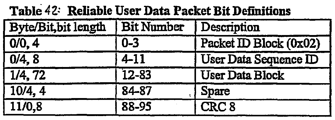


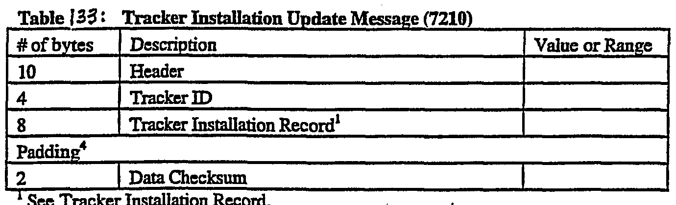
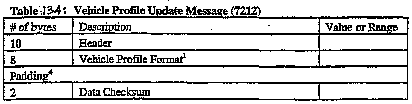
Claims
Priority Applications (3)
| Application Number | Priority Date | Filing Date | Title |
|---|---|---|---|
| EP00993539A EP1410364B1 (en) | 1999-12-19 | 2000-12-18 | Vehicle tracking, communication and fleet management system |
| DE60036650T DE60036650T2 (en) | 1999-12-19 | 2000-12-18 | VEHICLE TRACKING, COMMUNICATION, AND FLEET MANAGEMENT SYSTEM |
| AU29065/01A AU2906501A (en) | 1999-12-19 | 2000-12-18 | Vehicle tracking, communication and fleet management system |
Applications Claiming Priority (2)
| Application Number | Priority Date | Filing Date | Title |
|---|---|---|---|
| US09/466,169 US6611755B1 (en) | 1999-12-19 | 1999-12-19 | Vehicle tracking, communication and fleet management system |
| US09/466,169 | 1999-12-19 |
Publications (3)
| Publication Number | Publication Date |
|---|---|
| WO2001046710A2 true WO2001046710A2 (en) | 2001-06-28 |
| WO2001046710A3 WO2001046710A3 (en) | 2002-06-27 |
| WO2001046710A9 WO2001046710A9 (en) | 2002-12-05 |
Family
ID=23850779
Family Applications (1)
| Application Number | Title | Priority Date | Filing Date |
|---|---|---|---|
| PCT/US2000/033272 WO2001046710A2 (en) | 1999-12-19 | 2000-12-18 | Vehicle tracking, communication and fleet management system |
Country Status (8)
| Country | Link |
|---|---|
| US (4) | US6611755B1 (en) |
| EP (2) | EP1843161B1 (en) |
| AT (2) | ATE374987T1 (en) |
| AU (1) | AU2906501A (en) |
| DE (2) | DE60036650T2 (en) |
| ES (1) | ES2322627T3 (en) |
| HK (1) | HK1115449A1 (en) |
| WO (1) | WO2001046710A2 (en) |
Cited By (22)
| Publication number | Priority date | Publication date | Assignee | Title |
|---|---|---|---|---|
| EP1414002A1 (en) * | 2001-07-12 | 2004-04-28 | Hitachi Construction Machinery Co., Ltd. | Method for locating construcion machine, position plotting system, and construction machine |
| AU2003277269B2 (en) * | 2002-10-10 | 2008-12-11 | Caterpillar Inc. | System and method for managing a fleet of machines |
| EP2002329A2 (en) * | 2006-03-16 | 2008-12-17 | Smartdrive Systems, Inc. | Vehicle event recorder systems and networks having integrated cellular wireless communication systems |
| GB2432079B (en) * | 2005-11-08 | 2009-11-25 | Datong Electronics Ltd | Position tracking system |
| EP2482254A3 (en) * | 2011-01-26 | 2012-10-24 | The Goodyear Tire & Rubber Company | System and method for vehicle tracking |
| US8868288B2 (en) | 2006-11-09 | 2014-10-21 | Smartdrive Systems, Inc. | Vehicle exception event management systems |
| US8880279B2 (en) | 2005-12-08 | 2014-11-04 | Smartdrive Systems, Inc. | Memory management in event recording systems |
| US8892310B1 (en) | 2014-02-21 | 2014-11-18 | Smartdrive Systems, Inc. | System and method to detect execution of driving maneuvers |
| US8989959B2 (en) | 2006-11-07 | 2015-03-24 | Smartdrive Systems, Inc. | Vehicle operator performance history recording, scoring and reporting systems |
| US9183679B2 (en) | 2007-05-08 | 2015-11-10 | Smartdrive Systems, Inc. | Distributed vehicle event recorder systems having a portable memory data transfer system |
| US9402060B2 (en) | 2006-03-16 | 2016-07-26 | Smartdrive Systems, Inc. | Vehicle event recorders with integrated web server |
| US9501878B2 (en) | 2013-10-16 | 2016-11-22 | Smartdrive Systems, Inc. | Vehicle event playback apparatus and methods |
| US9554080B2 (en) | 2006-11-07 | 2017-01-24 | Smartdrive Systems, Inc. | Power management systems for automotive video event recorders |
| US9610955B2 (en) | 2013-11-11 | 2017-04-04 | Smartdrive Systems, Inc. | Vehicle fuel consumption monitor and feedback systems |
| US9633318B2 (en) | 2005-12-08 | 2017-04-25 | Smartdrive Systems, Inc. | Vehicle event recorder systems |
| US9663127B2 (en) | 2014-10-28 | 2017-05-30 | Smartdrive Systems, Inc. | Rail vehicle event detection and recording system |
| US9728228B2 (en) | 2012-08-10 | 2017-08-08 | Smartdrive Systems, Inc. | Vehicle event playback apparatus and methods |
| WO2018004425A1 (en) * | 2016-06-29 | 2018-01-04 | Scania Cv Ab | Method and system for determining the activity of at least one vehicle in a group of vehicles |
| US9888353B2 (en) | 2001-10-04 | 2018-02-06 | Traxcell Technologies Llc | Mobile wireless communications system and method with hierarchical location determination |
| US10930093B2 (en) | 2015-04-01 | 2021-02-23 | Smartdrive Systems, Inc. | Vehicle event recording system and method |
| US11069257B2 (en) | 2014-11-13 | 2021-07-20 | Smartdrive Systems, Inc. | System and method for detecting a vehicle event and generating review criteria |
| US20220129844A1 (en) * | 2020-07-09 | 2022-04-28 | Fourkites, Inc. | Supply chain visibility platform |
Families Citing this family (861)
| Publication number | Priority date | Publication date | Assignee | Title |
|---|---|---|---|---|
| US6919803B2 (en) | 2002-06-11 | 2005-07-19 | Intelligent Technologies International Inc. | Low power remote asset monitoring |
| US8948442B2 (en) * | 1982-06-18 | 2015-02-03 | Intelligent Technologies International, Inc. | Optical monitoring of vehicle interiors |
| US8352400B2 (en) | 1991-12-23 | 2013-01-08 | Hoffberg Steven M | Adaptive pattern recognition based controller apparatus and method and human-factored interface therefore |
| US10361802B1 (en) | 1999-02-01 | 2019-07-23 | Blanding Hovenweep, Llc | Adaptive pattern recognition based control system and method |
| US6169789B1 (en) * | 1996-12-16 | 2001-01-02 | Sanjay K. Rao | Intelligent keyboard system |
| WO1998053637A1 (en) * | 1997-05-21 | 1998-11-26 | E.S.P. Communications, Inc. | System, method and apparatus for 'caller only' initiated two-way wireless communication with caller generated billing |
| US6073007A (en) * | 1997-07-24 | 2000-06-06 | Qualcomm Incorporated | Wireless fleet communications system for providing separable communications services |
| US7548787B2 (en) * | 2005-08-03 | 2009-06-16 | Kamilo Feher | Medical diagnostic and communication system |
| US6470055B1 (en) | 1998-08-10 | 2002-10-22 | Kamilo Feher | Spectrally efficient FQPSK, FGMSK, and FQAM for enhanced performance CDMA, TDMA, GSM, OFDN, and other systems |
| US7079584B2 (en) * | 1998-08-10 | 2006-07-18 | Kamilo Feher | OFDM, CDMA, spread spectrum, TDMA, cross-correlated and filtered modulation |
| US7904187B2 (en) | 1999-02-01 | 2011-03-08 | Hoffberg Steven M | Internet appliance system and method |
| US7777675B2 (en) | 1999-03-05 | 2010-08-17 | Era Systems Corporation | Deployable passive broadband aircraft tracking |
| US7908077B2 (en) | 2003-06-10 | 2011-03-15 | Itt Manufacturing Enterprises, Inc. | Land use compatibility planning software |
| US7889133B2 (en) | 1999-03-05 | 2011-02-15 | Itt Manufacturing Enterprises, Inc. | Multilateration enhancements for noise and operations management |
| US7570214B2 (en) | 1999-03-05 | 2009-08-04 | Era Systems, Inc. | Method and apparatus for ADS-B validation, active and passive multilateration, and elliptical surviellance |
| US8203486B1 (en) | 1999-03-05 | 2012-06-19 | Omnipol A.S. | Transmitter independent techniques to extend the performance of passive coherent location |
| US7739167B2 (en) | 1999-03-05 | 2010-06-15 | Era Systems Corporation | Automated management of airport revenues |
| US7667647B2 (en) | 1999-03-05 | 2010-02-23 | Era Systems Corporation | Extension of aircraft tracking and positive identification from movement areas into non-movement areas |
| US7782256B2 (en) | 1999-03-05 | 2010-08-24 | Era Systems Corporation | Enhanced passive coherent location techniques to track and identify UAVs, UCAVs, MAVs, and other objects |
| US8446321B2 (en) | 1999-03-05 | 2013-05-21 | Omnipol A.S. | Deployable intelligence and tracking system for homeland security and search and rescue |
| US7072745B2 (en) | 1999-07-30 | 2006-07-04 | Oshkosh Truck Corporation | Refuse vehicle control system and method |
| US6885920B2 (en) * | 1999-07-30 | 2005-04-26 | Oshkosh Truck Corporation | Control system and method for electric vehicle |
| US20030158635A1 (en) * | 1999-07-30 | 2003-08-21 | Oshkosh Truck Corporation | Firefighting vehicle with network-assisted scene management |
| US6882917B2 (en) * | 1999-07-30 | 2005-04-19 | Oshkosh Truck Corporation | Steering control system and method |
| US7729831B2 (en) | 1999-07-30 | 2010-06-01 | Oshkosh Corporation | Concrete placement vehicle control system and method |
| US6993421B2 (en) * | 1999-07-30 | 2006-01-31 | Oshkosh Truck Corporation | Equipment service vehicle with network-assisted vehicle service and repair |
| US7184862B2 (en) * | 1999-07-30 | 2007-02-27 | Oshkosh Truck Corporation | Turret targeting system and method for a fire fighting vehicle |
| US6909944B2 (en) * | 1999-07-30 | 2005-06-21 | Oshkosh Truck Corporation | Vehicle control system and method |
| US6922615B2 (en) * | 1999-07-30 | 2005-07-26 | Oshkosh Truck Corporation | Turret envelope control system and method for a fire fighting vehicle |
| US7107129B2 (en) | 2002-02-28 | 2006-09-12 | Oshkosh Truck Corporation | Turret positioning system and method for a fire fighting vehicle |
| US6757597B2 (en) * | 2001-01-31 | 2004-06-29 | Oshkosh Truck | A/C bus assembly for electronic traction vehicle |
| US7127331B2 (en) | 1999-07-30 | 2006-10-24 | Oshkosh Truck Corporation | Turret operator interface system and method for a fire fighting vehicle |
| US20040133319A1 (en) * | 1999-07-30 | 2004-07-08 | Oshkosh Truck Corporation | User interface and method for vehicle control system |
| US7184866B2 (en) * | 1999-07-30 | 2007-02-27 | Oshkosh Truck Corporation | Equipment service vehicle with remote monitoring |
| US7006902B2 (en) | 1999-07-30 | 2006-02-28 | Oshkosh Truck Corporation | Control system and method for an equipment service vehicle |
| US7024296B2 (en) * | 1999-07-30 | 2006-04-04 | Oshkosh Truck Corporation | Control system and method for an equipment service vehicle |
| US6553290B1 (en) * | 2000-02-09 | 2003-04-22 | Oshkosh Truck Corporation | Equipment service vehicle having on-board diagnostic system |
| WO2001048624A1 (en) * | 1999-12-29 | 2001-07-05 | Glorikian Harry A | An internet system for connecting client-travelers with geographically-associated data |
| US6356841B1 (en) * | 1999-12-29 | 2002-03-12 | Bellsouth Intellectual Property Corporation | G.P.S. management system |
| US6587835B1 (en) | 2000-02-09 | 2003-07-01 | G. Victor Treyz | Shopping assistance with handheld computing device |
| JP2001253320A (en) * | 2000-03-13 | 2001-09-18 | Honda Motor Co Ltd | Vehicle monitoring system |
| US6606561B2 (en) * | 2000-05-17 | 2003-08-12 | Omega Patents, L.L.C. | Vehicle tracker including input/output features and related methods |
| US8032278B2 (en) * | 2000-05-17 | 2011-10-04 | Omega Patents, L.L.C. | Vehicle tracking unit with downloadable codes and associated methods |
| US7813875B2 (en) * | 2002-10-10 | 2010-10-12 | Sirf Technology, Inc. | Layered host based satellite positioning solutions |
| US7546395B2 (en) * | 2002-10-10 | 2009-06-09 | Sirf Technology, Inc. | Navagation processing between a tracker hardware device and a computer host based on a satellite positioning solution system |
| EP3373568A3 (en) | 2000-05-23 | 2018-11-07 | IoT IP GmbH | Programmable communicator |
| US6961659B2 (en) * | 2000-07-12 | 2005-11-01 | Ricoh Company Limited | Method and system of remote position reporting device |
| US7228211B1 (en) | 2000-07-25 | 2007-06-05 | Hti Ip, Llc | Telematics device for vehicles with an interface for multiple peripheral devices |
| US7904219B1 (en) | 2000-07-25 | 2011-03-08 | Htiip, Llc | Peripheral access devices and sensors for use with vehicle telematics devices and systems |
| US20020173885A1 (en) | 2001-03-13 | 2002-11-21 | Lowrey Larkin Hill | Internet-based system for monitoring vehicles |
| US6957133B1 (en) | 2003-05-08 | 2005-10-18 | Reynolds & Reynolds Holdings, Inc. | Small-scale, integrated vehicle telematics device |
| US7161476B2 (en) | 2000-07-26 | 2007-01-09 | Bridgestone Firestone North American Tire, Llc | Electronic tire management system |
| US8266465B2 (en) | 2000-07-26 | 2012-09-11 | Bridgestone Americas Tire Operation, LLC | System for conserving battery life in a battery operated device |
| US7092803B2 (en) * | 2000-08-18 | 2006-08-15 | Idsc Holdings, Llc | Remote monitoring, configuring, programming and diagnostic system and method for vehicles and vehicle components |
| US8310363B2 (en) * | 2002-06-11 | 2012-11-13 | Intelligent Technologies International, Inc. | Method and system for obtaining information about objects in an asset |
| US20020059420A1 (en) * | 2000-09-09 | 2002-05-16 | Ching-Fang Lin | Networked position multiple tracking process |
| US7337031B1 (en) * | 2000-10-26 | 2008-02-26 | I2 Technologies Us, Inc. | Optimized deployment of parts in a distribution network |
| DE10055087A1 (en) * | 2000-11-07 | 2002-05-16 | Bosch Gmbh Robert | Method for synchronizing a RF-receiver to RF-signals, involves using a phase-reference symbol as additional reference symbol in the RF-signals |
| CN1186740C (en) * | 2000-11-16 | 2005-01-26 | 株式会社Ntt都科摩 | Moving situation information providing method and server |
| SE518230C2 (en) * | 2000-12-12 | 2002-09-10 | Fredriksson Lars Berno | Mobile data and communication network for i.a. indoor use with frequency jump and time slot reuse |
| US7848905B2 (en) * | 2000-12-26 | 2010-12-07 | Troxler Electronic Laboratories, Inc. | Methods, systems, and computer program products for locating and tracking objects |
| US6915216B2 (en) | 2002-10-11 | 2005-07-05 | Troxler Electronic Laboratories, Inc. | Measurement device incorporating a locating device and a portable handheld computer device and associated apparatus, system and method |
| US7034695B2 (en) * | 2000-12-26 | 2006-04-25 | Robert Ernest Troxler | Large area position/proximity correction device with alarms using (D)GPS technology |
| US7277782B2 (en) | 2001-01-31 | 2007-10-02 | Oshkosh Truck Corporation | Control system and method for electric vehicle |
| US7379797B2 (en) | 2001-01-31 | 2008-05-27 | Oshkosh Truck Corporation | System and method for braking in an electric vehicle |
| US6968510B2 (en) * | 2001-02-05 | 2005-11-22 | Alpine Electronics, Inc. | Function executing apparatus and menu item displaying method therefor |
| US6678510B2 (en) * | 2001-02-05 | 2004-01-13 | Nokia Mobile Phones Ltd. | Method, apparatus and system for GPS time synchronization using cellular signal bursts |
| US20030028536A1 (en) * | 2001-02-27 | 2003-02-06 | Singh Hartej P. | Proactive emergency response system |
| US7523159B1 (en) | 2001-03-14 | 2009-04-21 | Hti, Ip, Llc | Systems, methods and devices for a telematics web services interface feature |
| DE10117130A1 (en) * | 2001-04-06 | 2002-11-28 | Bayerische Motoren Werke Ag | Process for the digital transmission of information via telephone connections |
| US6782350B1 (en) | 2001-04-27 | 2004-08-24 | Blazent, Inc. | Method and apparatus for managing resources |
| US7069239B2 (en) * | 2001-04-30 | 2006-06-27 | Nintendo Of America Inc. | System and method for tracking trailers |
| US6879894B1 (en) | 2001-04-30 | 2005-04-12 | Reynolds & Reynolds Holdings, Inc. | Internet-based emissions test for vehicles |
| JP4230132B2 (en) * | 2001-05-01 | 2009-02-25 | パナソニック株式会社 | Digital map shape vector encoding method, position information transmission method, and apparatus for implementing the same |
| AU2002305426A1 (en) * | 2001-05-07 | 2002-11-18 | C3 Trans Systems Llc | Autonomous vehicle collision/crossing warning system and method |
| US7925210B2 (en) | 2001-05-21 | 2011-04-12 | Sirf Technology, Inc. | Synchronizing a radio network with end user radio terminals |
| US7349691B2 (en) * | 2001-07-03 | 2008-03-25 | Microsoft Corporation | System and apparatus for performing broadcast and localcast communications |
| US6694235B2 (en) * | 2001-07-06 | 2004-02-17 | Denso Corporation | Vehicular relay device, in-vehicle communication system, failure diagnostic system, vehicle management device, server device and detection and diagnostic program |
| US6594579B1 (en) | 2001-08-06 | 2003-07-15 | Networkcar | Internet-based method for determining a vehicle's fuel efficiency |
| US7155321B2 (en) * | 2001-08-06 | 2006-12-26 | Idsc Holdings Llc | System, method and computer program product for remote vehicle diagnostics, monitoring, configuring and reprogramming |
| WO2003014752A1 (en) * | 2001-08-07 | 2003-02-20 | Vehicle Enhancement Systems, Inc. | Systems and methods for monitoring and storing performance and maintenance data related to an electrical component |
| US20030035518A1 (en) * | 2001-08-16 | 2003-02-20 | Fan Rodric C. | Voice interaction for location-relevant mobile resource management |
| US20030036938A1 (en) * | 2001-08-16 | 2003-02-20 | International Business Machines Corporation | Method and system for delivery of products within a predetermined time period |
| JP4194108B2 (en) * | 2001-10-12 | 2008-12-10 | オムロン株式会社 | Information processing apparatus, sensor network system, information processing program, and computer-readable recording medium on which information processing program is recorded |
| US6828924B2 (en) * | 2001-11-06 | 2004-12-07 | Volvo Trucks North America, Inc. | Integrated vehicle communications display |
| US8145448B2 (en) * | 2001-12-03 | 2012-03-27 | Fernando Vincenzini | System and process for charting and displaying the time and position of contestants in a race |
| US7174243B1 (en) | 2001-12-06 | 2007-02-06 | Hti Ip, Llc | Wireless, internet-based system for transmitting and analyzing GPS data |
| US20050113996A1 (en) * | 2001-12-21 | 2005-05-26 | Oshkosh Truck Corporation | Ambulance control system and method |
| US7302320B2 (en) | 2001-12-21 | 2007-11-27 | Oshkosh Truck Corporation | Failure mode operation for an electric vehicle |
| US7792618B2 (en) | 2001-12-21 | 2010-09-07 | Oshkosh Corporation | Control system and method for a concrete vehicle |
| US7714708B2 (en) * | 2001-12-28 | 2010-05-11 | Brackmann Rogers F | Smart pallet-box cargo container |
| US6897861B2 (en) * | 2002-01-09 | 2005-05-24 | Nissan Motor Co., Ltd. | Map image display device, map image display method and map image display program |
| US7948769B2 (en) | 2007-09-27 | 2011-05-24 | Hemisphere Gps Llc | Tightly-coupled PCB GNSS circuit and manufacturing method |
| US20030162523A1 (en) * | 2002-02-27 | 2003-08-28 | Michael Kapolka | Vehicle telemetry system and method |
| US7463616B1 (en) * | 2002-03-28 | 2008-12-09 | Nortel Networks Limited | Scheduling based on channel change indicia |
| US7103457B2 (en) * | 2002-03-28 | 2006-09-05 | Dean Technologies, Inc. | Programmable lawn mower |
| AU2003228377A1 (en) * | 2002-03-28 | 2003-10-13 | Jason Dean | Programmable lawn mower |
| WO2003088508A2 (en) * | 2002-04-09 | 2003-10-23 | Sapias, Inc. | Asset management platform |
| US20030195978A1 (en) * | 2002-04-11 | 2003-10-16 | International Business Machines Corporation | Audio buffer selective data processing |
| US20040030448A1 (en) * | 2002-04-22 | 2004-02-12 | Neal Solomon | System, methods and apparatus for managing external computation and sensor resources applied to mobile robotic network |
| US6993592B2 (en) * | 2002-05-01 | 2006-01-31 | Microsoft Corporation | Location measurement process for radio-frequency badges |
| US11337047B1 (en) | 2002-05-21 | 2022-05-17 | M2M Solutions Llc | System and method for remote asset management |
| GB0211644D0 (en) * | 2002-05-21 | 2002-07-03 | Wesby Philip B | System and method for remote asset management |
| FI20020964A0 (en) * | 2002-05-22 | 2002-05-22 | Nokia Corp | Method for Controlling a Satellite Communication System, a Timing Unit and a Timing Unit Control Unit |
| US6970774B2 (en) * | 2002-05-31 | 2005-11-29 | Quantum Engineering, Inc. | Method and system for compensating for wheel wear on a train |
| US7283897B2 (en) * | 2002-05-31 | 2007-10-16 | Quantum Engineering, Inc. | Method and system for compensating for wheel wear on a train |
| US8581688B2 (en) * | 2002-06-11 | 2013-11-12 | Intelligent Technologies International, Inc. | Coastal monitoring techniques |
| US7961094B2 (en) * | 2002-06-11 | 2011-06-14 | Intelligent Technologies International, Inc. | Perimeter monitoring techniques |
| US20040064333A1 (en) * | 2002-07-09 | 2004-04-01 | J'maev Jack I. | Method and apparatus for receiving product notices |
| US7412307B2 (en) * | 2002-08-02 | 2008-08-12 | Oshkosh Truck Corporation | Refuse vehicle control system and method |
| US7167912B1 (en) * | 2002-08-09 | 2007-01-23 | Cisco Technology, Inc. | Method and apparatus for detecting failures in network components |
| US7116993B2 (en) * | 2002-09-27 | 2006-10-03 | Rockwell Automation Technologies, Inc. | System and method for providing location based information |
| US7298275B2 (en) * | 2002-09-27 | 2007-11-20 | Rockwell Automation Technologies, Inc. | Machine associating method and apparatus |
| US6894454B2 (en) * | 2002-10-10 | 2005-05-17 | General Motors Corporation | Position sensorless control algorithm for AC machine |
| US6882906B2 (en) * | 2002-10-31 | 2005-04-19 | General Motors Corporation | Vehicle information and interaction management |
| US7356393B1 (en) * | 2002-11-18 | 2008-04-08 | Turfcentric, Inc. | Integrated system for routine maintenance of mechanized equipment |
| JP2004175052A (en) * | 2002-11-29 | 2004-06-24 | Sony Corp | Medium to be recorded by ink jetting, ink jet imaging method, and printed matter |
| US7885745B2 (en) | 2002-12-11 | 2011-02-08 | Hemisphere Gps Llc | GNSS control system and method |
| JP3839400B2 (en) * | 2002-12-16 | 2006-11-01 | 日立建機株式会社 | Anti-theft device |
| US7796944B2 (en) * | 2002-12-17 | 2010-09-14 | Motorola Mobility, Inc. | Communication system for dynamic management of a plurality of objects and method therefor |
| US6982656B1 (en) * | 2002-12-20 | 2006-01-03 | Innovative Processing Solutions, Llc | Asset monitoring and tracking system |
| US7613160B2 (en) * | 2002-12-24 | 2009-11-03 | Intel Corporation | Method and apparatus to establish communication with wireless communication networks |
| US20040153303A1 (en) * | 2002-12-30 | 2004-08-05 | Le Tang | Efficient process for time dependent network model in an energy market simulation system |
| JP2004220433A (en) * | 2003-01-16 | 2004-08-05 | Komatsu Ltd | Mobile machine management system |
| US7110728B2 (en) * | 2003-01-23 | 2006-09-19 | Komatsu Ltd. | Mobile body communication device |
| US7272456B2 (en) * | 2003-01-24 | 2007-09-18 | Rockwell Automation Technologies, Inc. | Position based machine control in an industrial automation environment |
| US7043316B2 (en) * | 2003-02-14 | 2006-05-09 | Rockwell Automation Technologies Inc. | Location based programming and data management in an automated environment |
| US7256711B2 (en) | 2003-02-14 | 2007-08-14 | Networks In Motion, Inc. | Method and system for saving and retrieving spatial related information |
| JP4142468B2 (en) * | 2003-02-28 | 2008-09-03 | 矢崎総業株式会社 | Traveling bus route acquisition system and arrival notification system |
| US7054760B2 (en) * | 2003-03-12 | 2006-05-30 | Youngquist John S | Apparatus and method for generating and displaying fuel flow information in a GPS-equipped vehicle |
| JP4337375B2 (en) * | 2003-03-14 | 2009-09-30 | 株式会社デンソー | Information distribution server, receiving terminal, information distribution system, reservation terminal, and reservation server |
| WO2004084471A2 (en) * | 2003-03-19 | 2004-09-30 | Home Data Source, Llc | Relative timing mechanism for event sequencing without clock synchronization |
| US8634993B2 (en) | 2003-03-20 | 2014-01-21 | Agjunction Llc | GNSS based control for dispensing material from vehicle |
| US9002565B2 (en) | 2003-03-20 | 2015-04-07 | Agjunction Llc | GNSS and optical guidance and machine control |
| US8271194B2 (en) | 2004-03-19 | 2012-09-18 | Hemisphere Gps Llc | Method and system using GNSS phase measurements for relative positioning |
| US8138970B2 (en) | 2003-03-20 | 2012-03-20 | Hemisphere Gps Llc | GNSS-based tracking of fixed or slow-moving structures |
| US8265826B2 (en) | 2003-03-20 | 2012-09-11 | Hemisphere GPS, LLC | Combined GNSS gyroscope control system and method |
| US8686900B2 (en) | 2003-03-20 | 2014-04-01 | Hemisphere GNSS, Inc. | Multi-antenna GNSS positioning method and system |
| US8140223B2 (en) | 2003-03-20 | 2012-03-20 | Hemisphere Gps Llc | Multiple-antenna GNSS control system and method |
| US8594879B2 (en) | 2003-03-20 | 2013-11-26 | Agjunction Llc | GNSS guidance and machine control |
| US8190337B2 (en) | 2003-03-20 | 2012-05-29 | Hemisphere GPS, LLC | Satellite based vehicle guidance control in straight and contour modes |
| US7272497B2 (en) * | 2003-03-24 | 2007-09-18 | Fuji Jukogyo Kabushiki Kaisha | Vehicle navigation system with multi-use display |
| US7415243B2 (en) | 2003-03-27 | 2008-08-19 | Honda Giken Kogyo Kabushiki Kaisha | System, method and computer program product for receiving data from a satellite radio network |
| EP2811678B1 (en) | 2003-03-31 | 2020-04-22 | Apple Inc. | A network apparatus, a memory medium and a method of operating the same with polling |
| US20050021223A1 (en) * | 2003-04-15 | 2005-01-27 | United Parcel Service Of America, Inc. | Rush hour modeling for routing and scheduling |
| US7188026B2 (en) * | 2003-05-12 | 2007-03-06 | Dash Navigation, Inc. | Hierarchical floating car data network |
| US6928358B2 (en) * | 2003-05-15 | 2005-08-09 | International Truck Intellectual Property Company, Llc | PTO-logic configuration system |
| US7272496B2 (en) * | 2003-06-12 | 2007-09-18 | Temic Automotive Of North America, Inc. | Vehicle network and method of communicating data packets in a vehicle network |
| US20080022940A1 (en) * | 2003-07-11 | 2008-01-31 | Bradley Kirsch | Composite Absorbent Particles with Superabsorbent Material |
| US7113127B1 (en) | 2003-07-24 | 2006-09-26 | Reynolds And Reynolds Holdings, Inc. | Wireless vehicle-monitoring system operating on both terrestrial and satellite networks |
| US9520005B2 (en) | 2003-07-24 | 2016-12-13 | Verizon Telematics Inc. | Wireless vehicle-monitoring system |
| US8060419B2 (en) * | 2003-07-31 | 2011-11-15 | Qualcomm Incorporated | Method and apparatus for providing separable billing services |
| US20080312941A1 (en) * | 2007-06-14 | 2008-12-18 | Qualcomm Incorporated | Separable billing for personal data services |
| JP4179945B2 (en) * | 2003-08-08 | 2008-11-12 | サンデン株式会社 | Vending machine terminal control device |
| JP4073022B2 (en) * | 2003-09-05 | 2008-04-09 | アルパイン株式会社 | On-vehicle device and other vehicle position calculation method |
| US20050100114A1 (en) * | 2003-09-12 | 2005-05-12 | Airbee Wireless, Inc. | System and method for data transmission |
| US7606577B2 (en) * | 2003-09-26 | 2009-10-20 | Siemens Communications, Inc. | System and method for alternative presence reporting system |
| US7848761B2 (en) * | 2003-09-26 | 2010-12-07 | Siemens Enterprise Communications, Inc. | System and method for global positioning system (GPS) based presence |
| US7202814B2 (en) * | 2003-09-26 | 2007-04-10 | Siemens Communications, Inc. | System and method for presence-based area monitoring |
| US7403786B2 (en) * | 2003-09-26 | 2008-07-22 | Siemens Communications, Inc. | System and method for in-building presence system |
| US7315746B2 (en) * | 2003-09-26 | 2008-01-01 | Siemens Communications, Inc. | System and method for speed-based presence state modification |
| US7546127B2 (en) * | 2003-09-26 | 2009-06-09 | Siemens Communications, Inc. | System and method for centrally-hosted presence reporting |
| US7224966B2 (en) * | 2003-09-26 | 2007-05-29 | Siemens Communications, Inc. | System and method for web-based presence perimeter rule monitoring |
| US7428417B2 (en) * | 2003-09-26 | 2008-09-23 | Siemens Communications, Inc. | System and method for presence perimeter rule downloading |
| US7848760B2 (en) * | 2003-09-26 | 2010-12-07 | Siemens Enterprise Communications, Inc. | System and method for presence alarming |
| US7885665B2 (en) | 2003-09-26 | 2011-02-08 | Siemens Enterprise Communications, Inc. | System and method for failsafe presence monitoring |
| US20050071498A1 (en) * | 2003-09-30 | 2005-03-31 | Farchmin David W. | Wireless location based automated components |
| WO2005039058A1 (en) * | 2003-10-17 | 2005-04-28 | Matsushita Electric Industrial Co., Ltd. | Encoding data generation method and device |
| US20050204310A1 (en) * | 2003-10-20 | 2005-09-15 | Aga De Zwart | Portable medical information device with dynamically configurable user interface |
| US7113797B2 (en) * | 2003-11-06 | 2006-09-26 | International Business Machines Corporation | System, method and program product for scheduling meetings |
| US7106219B2 (en) * | 2003-11-07 | 2006-09-12 | Pearce James W | Decentralized vehicular traffic status system |
| US20050114014A1 (en) * | 2003-11-24 | 2005-05-26 | Isaac Emad S. | System and method to notify a person of a traveler's estimated time of arrival |
| US7428450B1 (en) * | 2003-12-16 | 2008-09-23 | Garmin International, Inc | Method and system for using a database and GPS position data to generate bearing data |
| US20070138347A1 (en) * | 2004-12-16 | 2007-06-21 | Ehlers Gregory A | System and method for providing information to an operator of a vehicle |
| US7672677B2 (en) * | 2004-01-16 | 2010-03-02 | Compasscom Software Corporation | Method and system to transfer and to display location information about an object |
| US20050162309A1 (en) * | 2004-01-16 | 2005-07-28 | Mci, Inc. | Method and apparatus for data filtering in a tracking system |
| US7460871B2 (en) * | 2004-01-16 | 2008-12-02 | Skyguard, Llc | Method and system for tracking mobile telemetry devices |
| US20050184904A1 (en) * | 2004-01-16 | 2005-08-25 | Mci, Inc. | Data filtering by a telemetry device for fleet and asset management |
| US20050171835A1 (en) * | 2004-01-20 | 2005-08-04 | Mook David A. | System for monitoring economic trends in fleet management network |
| FR2865600B1 (en) * | 2004-01-26 | 2006-05-19 | Evolium Sas | DYNAMIC ADAPTATION OF DETECTION OF ACCESS DEMANDS TO A CELLULAR COMMUNICATIONS NETWORK, BASED ON THE RADIO ENVIRONMENT ASSOCIATED WITH THE APPLICANT COMMUNICATION EQUIPMENT |
| US7246009B2 (en) * | 2004-02-02 | 2007-07-17 | Glacier Northwest, Inc. | Resource management system, for example, tracking and management system for trucks |
| WO2005086460A1 (en) * | 2004-02-06 | 2005-09-15 | Sirf Technology, Inc. | Navigation processing in host based satellite positioning solution methods and systems |
| US7251535B2 (en) * | 2004-02-06 | 2007-07-31 | Rockwell Automation Technologies, Inc. | Location based diagnostics method and apparatus |
| CN1938135B (en) * | 2004-02-13 | 2012-12-26 | 验证有限责任公司 | Method and system for calculating and reporting slump in delivery vehicles |
| EP1571515A1 (en) * | 2004-03-04 | 2005-09-07 | Leica Geosystems AG | Method and apparatus for managing data relative to a worksite area |
| US8645569B2 (en) * | 2004-03-12 | 2014-02-04 | Rockwell Automation Technologies, Inc. | Juxtaposition based machine addressing |
| US8583315B2 (en) | 2004-03-19 | 2013-11-12 | Agjunction Llc | Multi-antenna GNSS control system and method |
| US7548758B2 (en) * | 2004-04-02 | 2009-06-16 | Nortel Networks Limited | System and method for peer-to-peer communication in cellular systems |
| US20050227705A1 (en) * | 2004-04-08 | 2005-10-13 | Seppo Rousu | Data communication method, telecommunication system and mobile device |
| US7225065B1 (en) | 2004-04-26 | 2007-05-29 | Hti Ip, Llc | In-vehicle wiring harness with multiple adaptors for an on-board diagnostic connector |
| US7123189B2 (en) * | 2004-05-13 | 2006-10-17 | Bushnell Performance Optics | Apparatus and method for allowing user to track path of travel over extended period of time |
| US20050253752A1 (en) * | 2004-05-13 | 2005-11-17 | Bushnell Performance Optics | Apparatus and method for allowing user to track path of travel over extended period of time |
| US20050273385A1 (en) * | 2004-06-04 | 2005-12-08 | David Vandervoort | Electronic advertising contract for granting fuel merchant credit in exchange for placement of advertising on vehicles |
| US7551137B2 (en) * | 2004-06-10 | 2009-06-23 | Tektrap Systems Inc. | Apparatus and method for tracing a path travelled by an entity or object, and tag for use therewith |
| US8870639B2 (en) | 2004-06-28 | 2014-10-28 | Winview, Inc. | Methods and apparatus for distributed gaming over a mobile device |
| US8376855B2 (en) * | 2004-06-28 | 2013-02-19 | Winview, Inc. | Methods and apparatus for distributed gaming over a mobile device |
| JP4286730B2 (en) * | 2004-06-30 | 2009-07-01 | 三菱電機株式会社 | Mobile information sharing system |
| GB0415219D0 (en) * | 2004-07-07 | 2004-08-11 | Koninkl Philips Electronics Nv | Improvements in or relating to time-of-flight ranging systems |
| US10226698B1 (en) | 2004-07-14 | 2019-03-12 | Winview, Inc. | Game of skill played by remote participants utilizing wireless devices in connection with a common game event |
| US7292159B2 (en) * | 2004-07-14 | 2007-11-06 | Spectrum Tracking Systems, Inc. | Method and system for providing tracking services to locate an asset |
| US7277048B2 (en) * | 2004-07-27 | 2007-10-02 | Preco Electronics, Inc. | Asset tracking method |
| US20060043933A1 (en) * | 2004-08-31 | 2006-03-02 | Latinis Gary R | Battery voltage monitor |
| US7643788B2 (en) | 2004-09-22 | 2010-01-05 | Honda Motor Co., Ltd. | Method and system for broadcasting data messages to a vehicle |
| US7250860B2 (en) * | 2004-09-30 | 2007-07-31 | Signature Control Systems, Inc. | Method and integrated system for networked control of an environment of a mobile object |
| US6972719B1 (en) * | 2004-09-30 | 2005-12-06 | Motorola, Inc. | Location determination system and method therefor |
| SE0402505L (en) * | 2004-10-14 | 2006-04-15 | Faelt Comm Ab | Device for a mobile telephone system |
| JP2006121542A (en) * | 2004-10-25 | 2006-05-11 | Sharp Corp | Radio transmittal system |
| GB2434884B (en) * | 2004-12-02 | 2009-04-08 | Ford Motor Co | Computer system and method for monitoring hydrogen vehicles |
| US8497761B2 (en) * | 2005-01-13 | 2013-07-30 | Rite-Hite Holding Corporation | System and method for remotely controlling docking station components |
| JP4517866B2 (en) * | 2005-01-28 | 2010-08-04 | 株式会社日立製作所 | Sensor data processing method |
| US20070229350A1 (en) * | 2005-02-01 | 2007-10-04 | Scalisi Joseph F | Apparatus and Method for Providing Location Information on Individuals and Objects using Tracking Devices |
| US7598855B2 (en) | 2005-02-01 | 2009-10-06 | Location Based Technologies, Inc. | Apparatus and method for locating individuals and objects using tracking devices |
| WO2006096773A2 (en) * | 2005-03-07 | 2006-09-14 | Networks In Motion, Inc. | Method and system for identifying and defining geofences |
| NZ538796A (en) * | 2005-03-10 | 2007-05-31 | Brunswick New Technologies Asi | Vehicle location and navigation system |
| US7685063B2 (en) * | 2005-03-25 | 2010-03-23 | The Crawford Group, Inc. | Client-server architecture for managing customer vehicle leasing |
| US7702361B2 (en) * | 2005-03-30 | 2010-04-20 | Nextel Communications Inc. | System and method for providing communication and positioning information |
| US7353034B2 (en) | 2005-04-04 | 2008-04-01 | X One, Inc. | Location sharing and tracking using mobile phones or other wireless devices |
| US8111680B2 (en) * | 2005-04-07 | 2012-02-07 | Mitsubishi Electric Corporation | Mobile object information sharing system |
| JP4652886B2 (en) * | 2005-04-28 | 2011-03-16 | 株式会社エヌ・ティ・ティ・ドコモ | Position estimation apparatus and position estimation method |
| US8443083B2 (en) * | 2005-05-04 | 2013-05-14 | Qualcomm Incorporated | Arbitration of resources at a wireless device among contending applications |
| JP2008543695A (en) * | 2005-05-09 | 2008-12-04 | ユナイテッド パーセル サービス オブ アメリカ インコーポレイテッド | System and method for routing and scheduling |
| US8559937B2 (en) * | 2005-06-07 | 2013-10-15 | Qualcomm Incorporated | Wireless system for providing critical sensor alerts for equipment |
| US10721543B2 (en) | 2005-06-20 | 2020-07-21 | Winview, Inc. | Method of and system for managing client resources and assets for activities on computing devices |
| EP1904196A2 (en) | 2005-06-20 | 2008-04-02 | Airplay Network, Inc. | Method of and system for managing client resources and assets for activities on computing devices |
| US7970345B2 (en) * | 2005-06-22 | 2011-06-28 | Atc Technologies, Llc | Systems and methods of waveform and/or information splitting for wireless transmission of information to one or more radioterminals over a plurality of transmission paths and/or system elements |
| JP2007011734A (en) * | 2005-06-30 | 2007-01-18 | Denso Corp | On-vehicle control unit |
| US7848881B2 (en) * | 2005-07-05 | 2010-12-07 | Containertrac, Inc. | Automatic past error corrections for location and inventory tracking |
| US7894982B2 (en) * | 2005-08-01 | 2011-02-22 | General Motors Llc | Method and system for linked vehicle navigation |
| US7280810B2 (en) * | 2005-08-03 | 2007-10-09 | Kamilo Feher | Multimode communication system |
| US7901710B2 (en) * | 2005-08-04 | 2011-03-08 | Vertical Pharmaceuticals, Inc. | Nutritional supplement for use under physiologically stressful conditions |
| US8202546B2 (en) | 2005-08-04 | 2012-06-19 | Vertical Pharmaceuticals, Inc. | Nutritional supplement for use under physiologically stressful conditions |
| US7998500B2 (en) * | 2005-08-04 | 2011-08-16 | Vertical Pharmaceuticals, Inc. | Nutritional supplement for women |
| US9818120B2 (en) | 2015-02-20 | 2017-11-14 | Innovative Global Systems, Llc | Automated at-the-pump system and method for managing vehicle fuel purchases |
| US7117075B1 (en) | 2005-08-15 | 2006-10-03 | Report On Board Llc | Driver activity and vehicle operation logging and reporting |
| US8626377B2 (en) | 2005-08-15 | 2014-01-07 | Innovative Global Systems, Llc | Method for data communication between a vehicle and fuel pump |
| US20070064518A1 (en) * | 2005-09-16 | 2007-03-22 | Goff Bryan H | System and method for controlling the release of pressurized fluid for concrete mixing |
| US9166823B2 (en) * | 2005-09-21 | 2015-10-20 | U Owe Me, Inc. | Generation of a context-enriched message including a message component and a contextual attribute |
| US9042921B2 (en) * | 2005-09-21 | 2015-05-26 | Buckyball Mobile Inc. | Association of context data with a voice-message component |
| US8472986B2 (en) * | 2005-09-21 | 2013-06-25 | Buckyball Mobile, Inc. | Method and system of optimizing context-data acquisition by a mobile device |
| US8509827B2 (en) * | 2005-09-21 | 2013-08-13 | Buckyball Mobile Inc. | Methods and apparatus of context-data acquisition and ranking |
| US8149530B1 (en) | 2006-04-12 | 2012-04-03 | Winview, Inc. | Methodology for equalizing systemic latencies in television reception in connection with games of skill played in connection with live television programming |
| US9511287B2 (en) | 2005-10-03 | 2016-12-06 | Winview, Inc. | Cellular phone games based upon television archives |
| US9919210B2 (en) | 2005-10-03 | 2018-03-20 | Winview, Inc. | Synchronized gaming and programming |
| US20070082689A1 (en) * | 2005-10-06 | 2007-04-12 | Talty Timothy J | Alert notification network |
| US8275402B2 (en) * | 2005-10-06 | 2012-09-25 | GM Global Technology Operations LLC | Alert notification network |
| US7852805B2 (en) * | 2005-11-01 | 2010-12-14 | Kahtava Jussi T | Variable length radio link ID for resource allocation in mobile communication systems |
| US7769105B1 (en) * | 2005-11-03 | 2010-08-03 | L-3 Communications, Corp. | System and method for communicating low data rate information with a radar system |
| US8606231B2 (en) | 2005-11-16 | 2013-12-10 | Sirius Xm Radio Inc. | Proprietary radio control head with authentication |
| US7761232B2 (en) * | 2005-12-06 | 2010-07-20 | Cypress Semiconductor Corporation | Wireless locating and monitoring system |
| WO2007133264A2 (en) * | 2005-12-09 | 2007-11-22 | Automotive Communications Systems, Inc. | Integrated vehicular positioning and communications system |
| US20070214258A1 (en) * | 2005-12-15 | 2007-09-13 | Venkateswaran Karrapanan | Real-time, self-directing updating of asset state |
| US20070140269A1 (en) * | 2005-12-20 | 2007-06-21 | Caterpillar Inc. | Cellular communication system on a work machine |
| WO2007073470A2 (en) | 2005-12-23 | 2007-06-28 | Perdiem, Llc | System and method for defining an event based on a relationship between an object location and a user-defined zone |
| US7525425B2 (en) | 2006-01-20 | 2009-04-28 | Perdiem Llc | System and method for defining an event based on relationship between an object location and a user-defined zone |
| US20070152844A1 (en) * | 2006-01-03 | 2007-07-05 | Hartley Joel S | Traffic condition monitoring devices and methods |
| US8002618B1 (en) | 2006-01-10 | 2011-08-23 | Winview, Inc. | Method of and system for conducting multiple contests of skill with a single performance |
| US10556183B2 (en) | 2006-01-10 | 2020-02-11 | Winview, Inc. | Method of and system for conducting multiple contest of skill with a single performance |
| US9056251B2 (en) | 2006-01-10 | 2015-06-16 | Winview, Inc. | Method of and system for conducting multiple contests of skill with a single performance |
| US8892116B2 (en) * | 2006-02-01 | 2014-11-18 | Omnitracs, Llc | Method and apparatus for enhanced privacy while tracking mobile workers |
| US7660652B2 (en) * | 2006-02-02 | 2010-02-09 | Signature Control Systems, Inc. | Method, system and device for monitoring vehicle usage |
| US9129233B2 (en) * | 2006-02-15 | 2015-09-08 | Catepillar Inc. | System and method for training a machine operator |
| US8825736B2 (en) * | 2006-03-14 | 2014-09-02 | Lifeworx, Inc. | System and method for service provider search |
| US7646336B2 (en) * | 2006-03-24 | 2010-01-12 | Containertrac, Inc. | Automated asset positioning for location and inventory tracking using multiple positioning techniques |
| US7966105B2 (en) | 2006-04-11 | 2011-06-21 | Asset Intelligence, Llc | Method and apparatus for power management of asset tracking system |
| US20070250452A1 (en) * | 2006-04-12 | 2007-10-25 | Christopher Leigh | Apparatus for an automotive data control, acquisition and transfer system |
| US11082746B2 (en) | 2006-04-12 | 2021-08-03 | Winview, Inc. | Synchronized gaming and programming |
| US20070241882A1 (en) * | 2006-04-18 | 2007-10-18 | Sapias, Inc. | User Interface for Real-Time Management of Vehicles |
| US8373567B2 (en) | 2006-05-08 | 2013-02-12 | Drivecam, Inc. | System and method for identifying non-event profiles |
| US7965227B2 (en) | 2006-05-08 | 2011-06-21 | Era Systems, Inc. | Aircraft tracking using low cost tagging as a discriminator |
| US9836716B2 (en) | 2006-05-09 | 2017-12-05 | Lytx, Inc. | System and method for reducing driving risk with hindsight |
| US8314708B2 (en) | 2006-05-08 | 2012-11-20 | Drivecam, Inc. | System and method for reducing driving risk with foresight |
| JP4746674B2 (en) * | 2006-05-12 | 2011-08-10 | 村田機械株式会社 | Transport system and transport method |
| US8223009B2 (en) * | 2006-05-15 | 2012-07-17 | TRACK America | Mobile asset tracking system and method |
| US20080294690A1 (en) * | 2007-05-22 | 2008-11-27 | Mcclellan Scott | System and Method for Automatically Registering a Vehicle Monitoring Device |
| US8630768B2 (en) | 2006-05-22 | 2014-01-14 | Inthinc Technology Solutions, Inc. | System and method for monitoring vehicle parameters and driver behavior |
| US20080258890A1 (en) * | 2006-05-22 | 2008-10-23 | Todd Follmer | System and Method for Remotely Deactivating a Vehicle |
| US9067565B2 (en) | 2006-05-22 | 2015-06-30 | Inthinc Technology Solutions, Inc. | System and method for evaluating driver behavior |
| WO2007144701A2 (en) * | 2006-06-13 | 2007-12-21 | Freescale Semiconductor, Inc. | A method and device for providing a security breach indicative audio alert |
| US8947531B2 (en) | 2006-06-19 | 2015-02-03 | Oshkosh Corporation | Vehicle diagnostics based on information communicated between vehicles |
| EP1870806A1 (en) * | 2006-06-19 | 2007-12-26 | Wolfgang Pree GmbH | System for executing distributed sofware |
| US8139109B2 (en) | 2006-06-19 | 2012-03-20 | Oshkosh Corporation | Vision system for an autonomous vehicle |
| US10056008B1 (en) | 2006-06-20 | 2018-08-21 | Zonar Systems, Inc. | Using telematics data including position data and vehicle analytics to train drivers to improve efficiency of vehicle use |
| US20080007398A1 (en) * | 2006-07-05 | 2008-01-10 | General Electric Company | System and method for tracking assets |
| AR054821A1 (en) * | 2006-07-06 | 2007-07-18 | Rosario Bus S A | PROVISION FOR INFORMATION, POSITIONING CONTROL AND PASSENGER TRANSPORTATION VEHICLE SCHEDULE. |
| US20080010016A1 (en) * | 2006-07-06 | 2008-01-10 | Wickey Edward S | Distribution Center Processing of Vehicles and Cargo |
| US20100011098A1 (en) * | 2006-07-09 | 2010-01-14 | 90 Degree Software Inc. | Systems and methods for managing networks |
| FR2903795B1 (en) * | 2006-07-12 | 2008-10-17 | Peugeot Citroen Automobiles Sa | FUEL QUALITY CONTROL SYSTEM DISTRIBUTED IN A MOTOR VEHICLE |
| US20080082257A1 (en) * | 2006-09-05 | 2008-04-03 | Garmin Ltd. | Personal navigational device and method with automatic call-ahead |
| US7894826B2 (en) * | 2006-09-07 | 2011-02-22 | Qualcomm Incorporated | Vehicle identification system |
| JP5069884B2 (en) * | 2006-09-14 | 2012-11-07 | 株式会社日立製作所 | Sensor network system for managing the latest data and history data |
| US7899610B2 (en) | 2006-10-02 | 2011-03-01 | Inthinc Technology Solutions, Inc. | System and method for reconfiguring an electronic control unit of a motor vehicle to optimize fuel economy |
| US9041561B2 (en) * | 2006-10-05 | 2015-05-26 | Trimble Navigation Limited | Method for controlling power usage of a reporting device |
| US20080086391A1 (en) * | 2006-10-05 | 2008-04-10 | Kurt Maynard | Impromptu asset tracking |
| US9747329B2 (en) * | 2006-10-05 | 2017-08-29 | Trimble Inc. | Limiting access to asset management information |
| US9519876B2 (en) * | 2006-10-05 | 2016-12-13 | Trimble Navigation Limited | Method for providing maintenance to an asset |
| US8965841B2 (en) * | 2006-10-05 | 2015-02-24 | Trimble Navigation Limited | Method for automatic asset classification |
| US9536405B2 (en) | 2006-10-05 | 2017-01-03 | Trimble Inc. | Unreported event status change determination and alerting |
| US9747571B2 (en) | 2006-10-05 | 2017-08-29 | Trimble Inc. | Integrated asset management |
| US20080086685A1 (en) * | 2006-10-05 | 2008-04-10 | James Janky | Method for delivering tailored asset information to a device |
| US8666936B2 (en) | 2006-10-05 | 2014-03-04 | Trimble Navigation Limited | System and method for asset management |
| US8645176B2 (en) * | 2006-10-05 | 2014-02-04 | Trimble Navigation Limited | Utilizing historical data in an asset management environment |
| US9811949B2 (en) | 2006-10-05 | 2017-11-07 | Trimble Inc. | Method for providing status information pertaining to an asset |
| US9773222B2 (en) * | 2006-10-05 | 2017-09-26 | Trimble Inc. | Externally augmented asset management |
| US9111234B2 (en) * | 2006-10-05 | 2015-08-18 | Trimble Navigation Limited | Enabling notifications pertaining to an asset |
| DE202006015589U1 (en) * | 2006-10-11 | 2006-12-28 | Zunhammer, Sebastian | Vehicle for spreading liquid manure, or as a trailer, has a sensor to measure the manure composition for evaluation to control the spreading rate |
| WO2008047521A1 (en) * | 2006-10-18 | 2008-04-24 | Nec Corporation | Mobile communication terminal with gps function, positioning system, operation control method, and program |
| US7530728B2 (en) * | 2006-10-24 | 2009-05-12 | Lars Rosaen | Water control apparatus |
| KR100826011B1 (en) * | 2006-10-24 | 2008-04-29 | 엘지디스플레이 주식회사 | Display device |
| WO2008064171A1 (en) * | 2006-11-20 | 2008-05-29 | At & T Corp. | Method and apparatus for providing geospatial and temporal navigation |
| US20080177436A1 (en) * | 2006-11-22 | 2008-07-24 | Fortson Frederick O | Diagnostic and telematic system |
| US20080122656A1 (en) * | 2006-11-27 | 2008-05-29 | Carani Sherry L | Tracking System and Method with Multiple Language Selector, Dynamic Screens and Multiple Screen Presentations |
| US8300591B1 (en) | 2006-12-08 | 2012-10-30 | Apple Inc. | Allocating resources in a frequency-time space to mobile station data |
| US20080147267A1 (en) * | 2006-12-13 | 2008-06-19 | Smartdrive Systems Inc. | Methods of Discretizing data captured at event data recorders |
| US8139820B2 (en) | 2006-12-13 | 2012-03-20 | Smartdrive Systems Inc. | Discretization facilities for vehicle event data recorders |
| US10013815B2 (en) | 2006-12-13 | 2018-07-03 | Crown Equipment Corporation | Information system for industrial vehicles |
| US11225404B2 (en) | 2006-12-13 | 2022-01-18 | Crown Equipment Corporation | Information system for industrial vehicles |
| US10600256B2 (en) | 2006-12-13 | 2020-03-24 | Crown Equipment Corporation | Impact sensing usable with fleet management system |
| US8249910B2 (en) * | 2006-12-13 | 2012-08-21 | Crown Equipment Corporation | Fleet management system |
| US9984341B2 (en) | 2006-12-13 | 2018-05-29 | Crown Equipment Corporation | Information system for industrial vehicles including cyclical recurring vehicle information message |
| US8838481B2 (en) | 2011-07-26 | 2014-09-16 | Golba Llc | Method and system for location based hands-free payment |
| US8838477B2 (en) | 2011-06-09 | 2014-09-16 | Golba Llc | Method and system for communicating location of a mobile device for hands-free payment |
| US8254348B2 (en) * | 2006-12-20 | 2012-08-28 | Honeywell International Inc. | Voice-over-internet protocol intra-vehicle communications |
| US8451807B2 (en) * | 2006-12-20 | 2013-05-28 | Honeywell International Inc. | Configuration aware packet routing in an ad-hoc network |
| US8059544B2 (en) * | 2006-12-20 | 2011-11-15 | Honeywell International Inc. | Distance adaptive routing protocol |
| US7729463B2 (en) * | 2006-12-22 | 2010-06-01 | Newport Media, Inc. | Host processor assisted fast re-synchronization techniques for DVB-H systems |
| US8365037B2 (en) * | 2007-01-03 | 2013-01-29 | GM Global Technology Operations LLC | Vehicle parameter infrastructure security strategy |
| US8311696B2 (en) | 2009-07-17 | 2012-11-13 | Hemisphere Gps Llc | Optical tracking vehicle control system and method |
| USRE48527E1 (en) | 2007-01-05 | 2021-04-20 | Agjunction Llc | Optical tracking vehicle control system and method |
| US7835832B2 (en) | 2007-01-05 | 2010-11-16 | Hemisphere Gps Llc | Vehicle control system |
| US8139680B2 (en) * | 2007-01-12 | 2012-03-20 | General Dynamics C4 Systems, Inc. | Signal acquisition methods and apparatus in wireless communication systems |
| US7907679B2 (en) * | 2007-01-12 | 2011-03-15 | General Dynamics C4 Systems, Inc. | Methods and systems for acquiring signals using coherent match filtering |
| US20080201197A1 (en) * | 2007-02-16 | 2008-08-21 | Rearden Commerce, Inc. | System and Method for Peer Person- And Situation-Based Recommendations |
| WO2008103955A2 (en) * | 2007-02-22 | 2008-08-28 | Backsen Ragnar H Jr | Apparatus, system, and method for enabling user-friendly, interactive communication and management of cartage transactions |
| US8000381B2 (en) | 2007-02-27 | 2011-08-16 | Hemisphere Gps Llc | Unbiased code phase discriminator |
| US9112815B2 (en) | 2012-06-15 | 2015-08-18 | Qualcomm Incorporated | Three-phase-polarity safe reverse link shutdown |
| US8064535B2 (en) | 2007-03-02 | 2011-11-22 | Qualcomm Incorporated | Three phase and polarity encoded serial interface |
| US9231790B2 (en) | 2007-03-02 | 2016-01-05 | Qualcomm Incorporated | N-phase phase and polarity encoded serial interface |
| US9711041B2 (en) | 2012-03-16 | 2017-07-18 | Qualcomm Incorporated | N-phase polarity data transfer |
| US20090027196A1 (en) * | 2007-03-07 | 2009-01-29 | Roland Schoettle | System and method for premises monitoring and control using self-learning detection devices |
| US20080218338A1 (en) * | 2007-03-07 | 2008-09-11 | Optimal Licensing Corporating | System and method for premises monitoring using weight detection |
| EP2118682B1 (en) * | 2007-03-08 | 2011-08-31 | Trimble AB | Methods and instruments for estimating target motion |
| US8497774B2 (en) | 2007-04-05 | 2013-07-30 | Location Based Technologies Inc. | Apparatus and method for adjusting refresh rate of location coordinates of a tracking device |
| US8224355B2 (en) * | 2007-11-06 | 2012-07-17 | Location Based Technologies Inc. | System and method for improved communication bandwidth utilization when monitoring location information |
| US8774827B2 (en) | 2007-04-05 | 2014-07-08 | Location Based Technologies, Inc. | Apparatus and method for generating position fix of a tracking device in accordance with a subscriber service usage profile to conserve tracking device power |
| US8244468B2 (en) * | 2007-11-06 | 2012-08-14 | Location Based Technology Inc. | System and method for creating and managing a personalized web interface for monitoring location information on individuals and objects using tracking devices |
| US9111189B2 (en) | 2007-10-31 | 2015-08-18 | Location Based Technologies, Inc. | Apparatus and method for manufacturing an electronic package |
| US8102256B2 (en) * | 2008-01-06 | 2012-01-24 | Location Based Technologies Inc. | Apparatus and method for determining location and tracking coordinates of a tracking device |
| US8600932B2 (en) | 2007-05-07 | 2013-12-03 | Trimble Navigation Limited | Telematic asset microfluidic analysis |
| US7756633B2 (en) * | 2007-05-11 | 2010-07-13 | Palo Alto Research Center Incorporated | System and method for security enhanced rideshare |
| US20080291022A1 (en) * | 2007-05-23 | 2008-11-27 | Erick Simon Amador | Automatic locating system |
| US8825277B2 (en) | 2007-06-05 | 2014-09-02 | Inthinc Technology Solutions, Inc. | System and method for the collection, correlation and use of vehicle collision data |
| US7876865B2 (en) * | 2007-06-08 | 2011-01-25 | COM DEV International Ltd | System and method for decoding automatic identification system signals |
| US20090161797A1 (en) * | 2007-06-08 | 2009-06-25 | Cowles Philip R | Satellite detection of automatic identification system signals |
| US8020431B2 (en) | 2007-06-19 | 2011-09-20 | Verifi, LLC | Method and system for calculating and reporting slump in delivery vehicles |
| US9518870B2 (en) | 2007-06-19 | 2016-12-13 | Verifi Llc | Wireless temperature sensor for concrete delivery vehicle |
| US8666590B2 (en) | 2007-06-22 | 2014-03-04 | Inthinc Technology Solutions, Inc. | System and method for naming, filtering, and recall of remotely monitored event data |
| US9129460B2 (en) | 2007-06-25 | 2015-09-08 | Inthinc Technology Solutions, Inc. | System and method for monitoring and improving driver behavior |
| GB0712377D0 (en) * | 2007-06-26 | 2007-08-01 | Nxp Bv | Road toll system |
| US8223678B2 (en) * | 2007-06-29 | 2012-07-17 | Intel Corporation | Power management of periodic transmissions from networking applications |
| US7999670B2 (en) | 2007-07-02 | 2011-08-16 | Inthinc Technology Solutions, Inc. | System and method for defining areas of interest and modifying asset monitoring in relation thereto |
| US9235938B2 (en) * | 2007-07-12 | 2016-01-12 | Omnitracs, Llc | Apparatus and method for measuring operational data for equipment using sensor breach durations |
| US8577703B2 (en) | 2007-07-17 | 2013-11-05 | Inthinc Technology Solutions, Inc. | System and method for categorizing driving behavior using driver mentoring and/or monitoring equipment to determine an underwriting risk |
| US8818618B2 (en) | 2007-07-17 | 2014-08-26 | Inthinc Technology Solutions, Inc. | System and method for providing a user interface for vehicle monitoring system users and insurers |
| US9117246B2 (en) | 2007-07-17 | 2015-08-25 | Inthinc Technology Solutions, Inc. | System and method for providing a user interface for vehicle mentoring system users and insurers |
| US8914267B2 (en) * | 2007-07-18 | 2014-12-16 | Chevron U.S.A. Inc. | Systems and methods for diagnosing production problems in oil field operations |
| US8827542B2 (en) | 2008-07-28 | 2014-09-09 | Ganado Technologies Corp. | Apparatus and method to feed livestock |
| US8746959B2 (en) | 2007-07-26 | 2014-06-10 | Ganado Technologies Corp. | Apparatus and method to feed livestock |
| US20090030609A1 (en) * | 2007-07-27 | 2009-01-29 | Rearden Commerce, Inc. | System and Method for Proactive Agenda Management |
| US20090030769A1 (en) * | 2007-07-27 | 2009-01-29 | Rearden Commerce, Inc. | System and Method for Latency Management Assistant |
| US8209075B2 (en) * | 2007-07-31 | 2012-06-26 | Deere & Company | Method and system for generating end turns |
| US7739015B2 (en) * | 2007-07-31 | 2010-06-15 | Deere & Company | System and method for controlling a vehicle with a sequence of vehicle events |
| US8635011B2 (en) | 2007-07-31 | 2014-01-21 | Deere & Company | System and method for controlling a vehicle in response to a particular boundary |
| US20090044964A1 (en) * | 2007-08-16 | 2009-02-19 | Optimal Innovations Inc. | Utility Outlets as a Security System |
| US8990400B2 (en) | 2007-08-17 | 2015-03-24 | The Invention Science Fund I, Llc | Facilitating communications among message recipients |
| US7733223B2 (en) * | 2007-08-17 | 2010-06-08 | The Invention Science Fund I, Llc | Effectively documenting irregularities in a responsive user's environment |
| US8583267B2 (en) | 2007-08-17 | 2013-11-12 | The Invention Science Fund I, Llc | Selective invocation of playback content supplementation |
| US20090051510A1 (en) * | 2007-08-21 | 2009-02-26 | Todd Follmer | System and Method for Detecting and Reporting Vehicle Damage |
| US8095279B2 (en) * | 2007-08-31 | 2012-01-10 | Caterpillar Inc. | Systems and methods for improving haul route management |
| US8099217B2 (en) * | 2007-08-31 | 2012-01-17 | Caterpillar Inc. | Performance-based haulage management system |
| US20090089772A1 (en) * | 2007-09-28 | 2009-04-02 | International Business Machines Corporation | Arrangement for scheduling jobs with rules and events |
| US7876205B2 (en) | 2007-10-02 | 2011-01-25 | Inthinc Technology Solutions, Inc. | System and method for detecting use of a wireless device in a moving vehicle |
| US8099308B2 (en) | 2007-10-02 | 2012-01-17 | Honda Motor Co., Ltd. | Method and system for vehicle service appointments based on diagnostic trouble codes |
| US7808428B2 (en) | 2007-10-08 | 2010-10-05 | Hemisphere Gps Llc | GNSS receiver and external storage device system and GNSS data processing method |
| US8014924B2 (en) * | 2007-10-12 | 2011-09-06 | Caterpillar Inc. | Systems and methods for improving haul road conditions |
| US8078441B2 (en) * | 2007-10-12 | 2011-12-13 | Caterpillar Inc. | Systems and methods for designing a haul road |
| US20090099886A1 (en) * | 2007-10-12 | 2009-04-16 | Caterpillar Inc. | System and method for performance-based payload management |
| US20090099720A1 (en) * | 2007-10-16 | 2009-04-16 | Elgali Mordechai | Monitoring the operation and maintenance of vehicles |
| US8654974B2 (en) * | 2007-10-18 | 2014-02-18 | Location Based Technologies, Inc. | Apparatus and method to provide secure communication over an insecure communication channel for location information using tracking devices |
| US20090102679A1 (en) * | 2007-10-19 | 2009-04-23 | Optimal Innovations Inc. | Infrastructure device with removable face plate for remote operation |
| US20090101386A1 (en) * | 2007-10-19 | 2009-04-23 | Optimal Innovations Inc. | Size unconstrained faceplate display for use with infrastructure device |
| US20090287527A1 (en) * | 2007-10-19 | 2009-11-19 | Siemens Aktiengesellschaft | Device for communicating orders for transportation, vehicle-base communication device, communication system and method |
| DE102008015232A1 (en) * | 2007-11-15 | 2009-05-20 | Continental Teves Ag & Co. Ohg | Transmission of vehicle information |
| US20090135006A1 (en) * | 2007-11-26 | 2009-05-28 | Optimal Innovations Inc. | Infrastructure device with modular remote sensors |
| US20090137163A1 (en) * | 2007-11-26 | 2009-05-28 | Optimal Innovations Inc. | Infrastructure device with modular replaceable sensors |
| AU2007237287C1 (en) * | 2007-11-30 | 2013-09-19 | Transport Certification Australia Limited | System for monitoring vehicle use |
| US8116632B2 (en) * | 2007-11-30 | 2012-02-14 | Raytheon Company | Space-time division multiple-access laser communications system |
| US20090157461A1 (en) * | 2007-12-12 | 2009-06-18 | Honeywell International Inc. | Vehicle deployment planning system |
| US8090560B2 (en) * | 2007-12-14 | 2012-01-03 | Caterpillar Inc. | Systems and methods for haul road management based on greenhouse gas emissions |
| US7864775B2 (en) * | 2007-12-20 | 2011-01-04 | Honeywell International Inc. | Automatic sequencing based on wireless connectivity |
| US20090160646A1 (en) * | 2007-12-20 | 2009-06-25 | General Electric Company | System and method for monitoring and tracking inventories |
| WO2009082745A1 (en) * | 2007-12-22 | 2009-07-02 | Hemisphere Gps Llc | Integrated dead reckoning and gnss/ins positioning |
| US20100161179A1 (en) * | 2008-12-22 | 2010-06-24 | Mcclure John A | Integrated dead reckoning and gnss/ins positioning |
| JP4592743B2 (en) * | 2007-12-28 | 2010-12-08 | 古野電気株式会社 | Synchronization device and synchronization method |
| US20090177336A1 (en) * | 2008-01-07 | 2009-07-09 | Mcclellan Scott | System and Method for Triggering Vehicle Functions |
| US8218519B1 (en) * | 2008-01-23 | 2012-07-10 | Rockwell Collins, Inc. | Transmit ID within an ad hoc wireless communications network |
| US8064377B2 (en) * | 2008-01-24 | 2011-11-22 | Honeywell International Inc. | Method for enhancement of multicasting forwarding protocol in a wireless network |
| US7978610B1 (en) | 2008-01-24 | 2011-07-12 | L-3 Communications Corp. | Method for asynchronous transmission of communication data between periodically blanked terminals |
| US8130680B1 (en) | 2008-01-24 | 2012-03-06 | L-3 Communications, Corp. | Method for timing a pulsed communication system |
| US8179286B2 (en) * | 2008-01-29 | 2012-05-15 | Qualcomm Incorporated | System and method for sensing cargo loads and trailer movement |
| US20090199192A1 (en) * | 2008-02-05 | 2009-08-06 | Robert Laithwaite | Resource scheduling apparatus and method |
| WO2009100463A1 (en) | 2008-02-10 | 2009-08-13 | Hemisphere Gps Llc | Visual, gnss and gyro autosteering control |
| US8131432B2 (en) | 2008-02-27 | 2012-03-06 | Deere & Company | Method and system for managing the turning of a vehicle |
| US8848810B2 (en) * | 2008-03-05 | 2014-09-30 | Qualcomm Incorporated | Multiple transmitter system and method |
| US8204654B2 (en) * | 2008-03-20 | 2012-06-19 | Deere & Company | System and method for generation of an inner boundary of a work area |
| WO2009126587A1 (en) | 2008-04-08 | 2009-10-15 | Hemisphere Gps Llc | Gnss-based mobile communication system and method |
| US7928724B2 (en) * | 2008-05-27 | 2011-04-19 | Honeywell International Inc. | Magnetic odometer with direction indicator systems and method |
| US20090307265A1 (en) * | 2008-06-06 | 2009-12-10 | Exel Inc. | Method of operating a warehouse |
| US20090307039A1 (en) * | 2008-06-09 | 2009-12-10 | Nathaniel Seeds | System and method for managing work instructions for vehicles |
| BRPI0909562A2 (en) * | 2008-06-27 | 2015-09-22 | Ford Global Tech Llc | apparatus for recording events in a vehicle |
| US10083493B1 (en) | 2008-07-11 | 2018-09-25 | Creative Mobile Technologies, LLC | Vehicle fleet management |
| US20100034183A1 (en) * | 2008-08-05 | 2010-02-11 | Broadcom Corporation | Flexible WLAN/WPAN system with high throughput |
| US20110137699A1 (en) * | 2008-08-05 | 2011-06-09 | Ronen Ben-Ari | Method and system for cab management |
| US8688180B2 (en) | 2008-08-06 | 2014-04-01 | Inthinc Technology Solutions, Inc. | System and method for detecting use of a wireless device while driving |
| AU2009289638A1 (en) * | 2008-09-03 | 2010-03-11 | Snif Labs, Inc. | Activity state classification |
| US8380640B2 (en) | 2008-09-04 | 2013-02-19 | United Parcel Service Of America, Inc. | Driver training systems |
| EP2332134A4 (en) * | 2008-09-04 | 2012-04-11 | United Parcel Service Inc | Determining vehicle visit costs to a geographic area |
| US10453004B2 (en) * | 2008-09-04 | 2019-10-22 | United Parcel Service Of America, Inc. | Vehicle routing and scheduling systems |
| US8219312B2 (en) | 2008-09-04 | 2012-07-10 | United Parcel Service Of America, Inc. | Determining speed parameters in a geographic area |
| CN102203810A (en) | 2008-09-09 | 2011-09-28 | 美国联合包裹服务公司 | Systems and methods of utilizing telematics data to improve fleet management operations |
| US11482058B2 (en) | 2008-09-09 | 2022-10-25 | United Parcel Service Of America, Inc. | Systems and methods for utilizing telematics data to improve fleet management operations |
| US9264856B1 (en) | 2008-09-10 | 2016-02-16 | Dominic M. Kotab | Geographical applications for mobile devices and backend systems |
| US11231289B2 (en) * | 2008-09-10 | 2022-01-25 | Dominic M. Kotab | Systems, methods and computer program products for sharing geographical data |
| US20100082179A1 (en) * | 2008-09-29 | 2010-04-01 | David Kronenberg | Methods for Linking Motor Vehicles to Reduce Aerodynamic Drag and Improve Fuel Economy |
| US8639591B1 (en) | 2008-09-30 | 2014-01-28 | Amazon Technologies, Inc. | System and method for generating a visual display indicating the status of multiple shipping loads |
| US9716918B1 (en) | 2008-11-10 | 2017-07-25 | Winview, Inc. | Interactive advertising system |
| WO2010056860A1 (en) * | 2008-11-12 | 2010-05-20 | Stemco Lp | On-board low-power vehicle condition indicator |
| CN102227922A (en) * | 2008-11-28 | 2011-10-26 | 三洋电机株式会社 | Notification method and wireless device |
| US8217833B2 (en) | 2008-12-11 | 2012-07-10 | Hemisphere Gps Llc | GNSS superband ASIC with simultaneous multi-frequency down conversion |
| US7974194B2 (en) * | 2008-12-12 | 2011-07-05 | Microsoft Corporation | Optimizing data traffic and power consumption in mobile unified communication applications |
| US8463469B2 (en) * | 2008-12-17 | 2013-06-11 | General Electric Company | Digital railroad system |
| US20100179723A1 (en) * | 2009-01-13 | 2010-07-15 | General Motors Corporation@@Gm Global Technology Operations, Inc. | Driver behavior based remote vehicle mis-usage warning and self-maintenance |
| JP5746976B2 (en) * | 2009-01-14 | 2015-07-08 | トムトム インターナショナル ベスローテン フエンノートシャップ | Apparatus and method for generating supplementary information for digital map, computer program, and machine-readable information medium |
| US8002128B2 (en) * | 2009-01-15 | 2011-08-23 | Kern Karl C | Decking beam rack apparatus and method |
| US8386129B2 (en) | 2009-01-17 | 2013-02-26 | Hemipshere GPS, LLC | Raster-based contour swathing for guidance and variable-rate chemical application |
| US8892341B2 (en) | 2009-02-13 | 2014-11-18 | Inthinc Technology Solutions, Inc. | Driver mentoring to improve vehicle operation |
| US8963702B2 (en) | 2009-02-13 | 2015-02-24 | Inthinc Technology Solutions, Inc. | System and method for viewing and correcting data in a street mapping database |
| US8188887B2 (en) | 2009-02-13 | 2012-05-29 | Inthinc Technology Solutions, Inc. | System and method for alerting drivers to road conditions |
| US8085196B2 (en) | 2009-03-11 | 2011-12-27 | Hemisphere Gps Llc | Removing biases in dual frequency GNSS receivers using SBAS |
| CA2756771C (en) | 2009-03-27 | 2017-08-01 | Verifi Llc | Mixer waveform analysis for monitoring and controlling concrete |
| US8818561B2 (en) | 2009-03-27 | 2014-08-26 | Verifi Llc | Slump flow monitoring |
| WO2010114478A1 (en) * | 2009-03-31 | 2010-10-07 | Azimuth Intellectual Products Pte Ltd | Apparatus and methods for analysing goods cartons |
| US8156264B2 (en) * | 2009-04-03 | 2012-04-10 | Analog Devices, Inc. | Digital output sensor FIFO buffer with single port memory |
| BRPI1013676A2 (en) * | 2009-04-03 | 2016-04-26 | Crown Equip Corp | methods for tracking the use of an industrial vehicle, for collecting information related to a lockout event occurring on an industrial vehicle, and for enabling a replacement for a normal industrial vehicle registration procedure; and, industrial vehicle |
| US20100287025A1 (en) * | 2009-05-06 | 2010-11-11 | Brian Fletcher | Mobile resource task scheduling |
| US9358924B1 (en) * | 2009-05-08 | 2016-06-07 | Eagle Harbor Holdings, Llc | System and method for modeling advanced automotive safety systems |
| CA2765254C (en) | 2009-06-12 | 2016-11-22 | Safemine Ag | Movable object proximity warning system |
| CN101938640A (en) * | 2009-06-29 | 2011-01-05 | 中兴通讯股份有限公司 | Method for improving broadcast channel frame utilization factor, application method of filing part and device |
| US8224370B2 (en) * | 2009-07-10 | 2012-07-17 | Honda Motor Co., Ltd. | Method of controlling a communication system in a motor vehicle |
| US20110016343A1 (en) * | 2009-07-15 | 2011-01-20 | International Truck Intellectual Property Company, Llc | Synchronizing a Clock in a Vehicle Telematic System |
| US8401704B2 (en) | 2009-07-22 | 2013-03-19 | Hemisphere GPS, LLC | GNSS control system and method for irrigation and related applications |
| US8174437B2 (en) | 2009-07-29 | 2012-05-08 | Hemisphere Gps Llc | System and method for augmenting DGNSS with internally-generated differential correction |
| RU2517334C2 (en) | 2009-08-12 | 2014-05-27 | КРАУН ЭКВАЙПМЕНТ КОРПОРЕЙШН, Корпорация штата Огайо | Info system for industrial machines |
| MX2012001497A (en) | 2009-08-14 | 2012-06-19 | Telogis Inc | Real time map rendering with data clustering and expansion and overlay. |
| WO2011025533A1 (en) * | 2009-08-25 | 2011-03-03 | Inthinc Technology Solutions, Inc. | System and method for determining relative positions of moving objects and sequence of objects |
| BR112012004602A2 (en) * | 2009-09-01 | 2016-04-05 | Crown Equip Corp | methods for dynamically generating truck information and automatically monitoring truck information |
| US8334804B2 (en) | 2009-09-04 | 2012-12-18 | Hemisphere Gps Llc | Multi-frequency GNSS receiver baseband DSP |
| US9084071B2 (en) * | 2009-09-10 | 2015-07-14 | Michael-Anthony Lisboa | Simple mobile registration mechanism enabling automatic registration via mobile devices |
| US8557070B2 (en) | 2009-09-14 | 2013-10-15 | Joel A. Stanley | Method of mounting objects to polymeric membranes |
| US8649930B2 (en) | 2009-09-17 | 2014-02-11 | Agjunction Llc | GNSS integrated multi-sensor control system and method |
| US8255146B2 (en) * | 2009-09-23 | 2012-08-28 | Sudharshan Srinivasan | Time slot based roadway traffic management system |
| US9633327B2 (en) | 2009-09-25 | 2017-04-25 | Fedex Corporate Services, Inc. | Sensor zone management |
| US8239169B2 (en) | 2009-09-25 | 2012-08-07 | Gregory Timothy L | Portable computing device and method for asset management in a logistics system |
| US8299920B2 (en) | 2009-09-25 | 2012-10-30 | Fedex Corporate Services, Inc. | Sensor based logistics system |
| US8780788B2 (en) | 2009-09-25 | 2014-07-15 | Com Dev International Ltd. | Systems and methods for decoding automatic identification system signals |
| US9367967B2 (en) * | 2009-09-29 | 2016-06-14 | GM Global Technology Operations LLC | Systems and methods for odometer monitoring |
| US8473818B2 (en) * | 2009-10-12 | 2013-06-25 | Empire Technology Development Llc | Reliable communications in on-chip networks |
| IT1395947B1 (en) * | 2009-10-15 | 2012-11-02 | Meta System Spa | ELECTRIC BATTERY FOR VEHICLES |
| US8548649B2 (en) | 2009-10-19 | 2013-10-01 | Agjunction Llc | GNSS optimized aircraft control system and method |
| US8618957B2 (en) * | 2009-10-23 | 2013-12-31 | Lojack Corporation | Power management system and method for vehicle locating unit |
| US20110098880A1 (en) * | 2009-10-23 | 2011-04-28 | Basir Otman A | Reduced transmission of vehicle operating data |
| US20110112943A1 (en) * | 2009-11-09 | 2011-05-12 | Dietz Jay B | Location-based mobile workforce management system |
| CN102074109B (en) * | 2009-11-24 | 2012-12-26 | 深圳市赛格导航科技股份有限公司 | Method and system for scheduling vehicles |
| US9848114B2 (en) | 2009-12-07 | 2017-12-19 | Cobra Electronics Corporation | Vehicle camera system |
| US9132773B2 (en) | 2009-12-07 | 2015-09-15 | Cobra Electronics Corporation | Mobile communication system and method for analyzing alerts associated with vehicular travel |
| WO2011071826A1 (en) * | 2009-12-07 | 2011-06-16 | Cobra Electronics Corporation | Analyzing data from networked radar detectors |
| US8706349B2 (en) | 2009-12-07 | 2014-04-22 | At&T Mobility Ii Llc | Devices, systems and methods for controlling permitted settings on a vehicle |
| US8452989B1 (en) * | 2009-12-09 | 2013-05-28 | Emc Corporation | Providing security to an electronic device |
| US8994557B2 (en) | 2009-12-11 | 2015-03-31 | Safemine Ag | Modular collision warning apparatus and method for operating the same |
| RU2525835C2 (en) | 2009-12-22 | 2014-08-20 | Кобра Электроникс Корпорейшн | Radar detector interacting with mobile communication device |
| US8378843B2 (en) * | 2009-12-22 | 2013-02-19 | General Electric Company | System and method to provide value added services in an asset network |
| CA2726160A1 (en) * | 2009-12-31 | 2011-06-30 | Trapeze Software Inc. | System and method for storing performance data in a transit organization |
| US8301364B2 (en) * | 2010-01-27 | 2012-10-30 | Navteq B.V. | Method of operating a navigation system to provide geographic location information |
| US8583326B2 (en) | 2010-02-09 | 2013-11-12 | Agjunction Llc | GNSS contour guidance path selection |
| AU2010347253B2 (en) * | 2010-03-03 | 2014-10-23 | International Truck Intellectual Property Company, Llc | Angular velocity control for hybrid vehicle prime movers |
| JP5069325B2 (en) * | 2010-03-11 | 2012-11-07 | 株式会社豊田中央研究所 | Task execution control device and program |
| US8805592B1 (en) * | 2010-03-11 | 2014-08-12 | Cascades Coal Sales, Inc. | Fluid identification and tracking |
| CN101854724B (en) * | 2010-03-30 | 2013-02-06 | 中国人民解放军信息工程大学 | Distributed multiinput-multioutput orthogonal frequency division multiplexing system and resource allocation method in same |
| US8836490B2 (en) * | 2010-04-09 | 2014-09-16 | Dsg Tag Systems Inc. | Vehicle management |
| US9280902B2 (en) * | 2010-04-09 | 2016-03-08 | DSG TAG Systems, Inc. | Facilities management |
| US8417448B1 (en) | 2010-04-14 | 2013-04-09 | Jason Adam Denise | Electronic direction technology |
| US8412254B2 (en) | 2010-06-02 | 2013-04-02 | R&L Carriers, Inc. | Intelligent wireless dispatch systems |
| US9331774B2 (en) | 2010-06-09 | 2016-05-03 | Exactearth Ltd. | Systems and methods for segmenting a satellite field of view for detecting radio frequency signals |
| US8311678B2 (en) | 2010-06-23 | 2012-11-13 | Verifi Llc | Method for adjusting concrete rheology based upon nominal dose-response profile |
| US9789629B2 (en) | 2010-06-23 | 2017-10-17 | Verifi Llc | Method for adjusting concrete rheology based upon nominal dose-response profile |
| US9453915B2 (en) * | 2010-06-29 | 2016-09-27 | Nokia Technologies Oy | Portable communication terminals and methods for cooperative positioning support during poor satellite coverage |
| US8626553B2 (en) * | 2010-07-30 | 2014-01-07 | General Motors Llc | Method for updating an electronic calendar in a vehicle |
| MX2013001902A (en) | 2010-08-17 | 2013-06-07 | Verifi Llc | Wireless temperature sensor for concrete delivery vehicle. |
| GB2484085B (en) * | 2010-09-28 | 2014-05-07 | Cassidian Ltd | Telecommunications network routing |
| US8275508B1 (en) | 2011-03-03 | 2012-09-25 | Telogis, Inc. | History timeline display for vehicle fleet management |
| US20120131111A1 (en) * | 2010-11-24 | 2012-05-24 | Honeywell International Inc. | Methods and apparatus for point-and-click messaging |
| KR101101797B1 (en) * | 2010-12-03 | 2012-01-05 | 삼성에스디에스 주식회사 | Wireless terminal and method for managing network connection using the same |
| US8514859B2 (en) * | 2010-12-14 | 2013-08-20 | At&T Intellectual Property I, L.P. | Methods and apparatus to determine an alternate route in a network |
| US9915755B2 (en) | 2010-12-20 | 2018-03-13 | Ford Global Technologies, Llc | Virtual ambient weather condition sensing |
| US8442555B2 (en) * | 2010-12-31 | 2013-05-14 | Trimble Navigation Limited | Fleet management system and method employing mobile device monitoring and research |
| US11814821B2 (en) | 2011-01-03 | 2023-11-14 | Sentinel Hydrosolutions, Llc | Non-invasive thermal dispersion flow meter with fluid leak detection and geo-fencing control |
| US9721473B2 (en) | 2011-01-13 | 2017-08-01 | Trimble Inc. | Asset tracking system |
| US10296977B2 (en) * | 2011-01-17 | 2019-05-21 | Imetrik Technologies Inc. | Computer-implemented method and system for reporting a confidence score in relation to a vehicle equipped with a wireless-enabled usage reporting device |
| US20120185111A1 (en) * | 2011-01-18 | 2012-07-19 | Control-Tec, Llc | Multiple-mode data acquisition system |
| US8718536B2 (en) | 2011-01-18 | 2014-05-06 | Marwan Hannon | Apparatus, system, and method for detecting the presence and controlling the operation of mobile devices within a vehicle |
| US8686864B2 (en) | 2011-01-18 | 2014-04-01 | Marwan Hannon | Apparatus, system, and method for detecting the presence of an intoxicated driver and controlling the operation of a vehicle |
| DE102011009483A1 (en) * | 2011-01-26 | 2012-07-26 | Audi Ag | Method for operating a longitudinal driver assistance system of a motor vehicle and motor vehicle |
| JP5267598B2 (en) * | 2011-02-25 | 2013-08-21 | トヨタ自動車株式会社 | Data rewrite support system and data rewrite support method for vehicle control device |
| US9129449B2 (en) | 2011-03-31 | 2015-09-08 | United Parcel Service Of America, Inc. | Calculating speed and travel times with travel delays |
| US9953468B2 (en) | 2011-03-31 | 2018-04-24 | United Parcel Service Of America, Inc. | Segmenting operational data |
| US8996287B2 (en) | 2011-03-31 | 2015-03-31 | United Parcel Service Of America, Inc. | Calculating speed and travel times with travel delays |
| US9208626B2 (en) | 2011-03-31 | 2015-12-08 | United Parcel Service Of America, Inc. | Systems and methods for segmenting operational data |
| JPWO2012133410A1 (en) * | 2011-03-31 | 2014-07-28 | 日立建機株式会社 | Positioning support system for transporting machines |
| US9070100B2 (en) | 2011-03-31 | 2015-06-30 | United Parcel Service Of America, Inc. | Calculating speed and travel times with travel delays |
| US8911138B2 (en) | 2011-03-31 | 2014-12-16 | Verifi Llc | Fluid dispensing system and method for concrete mixer |
| US9117190B2 (en) | 2011-03-31 | 2015-08-25 | United Parcel Service Of America, Inc. | Calculating speed and travel times with travel delays |
| US8727056B2 (en) | 2011-04-01 | 2014-05-20 | Navman Wireless North America Ltd. | Systems and methods for generating and using moving violation alerts |
| US9346365B1 (en) * | 2011-04-22 | 2016-05-24 | Angel A. Penilla | Methods and systems for electric vehicle (EV) charging, charging unit (CU) interfaces, auxiliary batteries, and remote access and user notifications |
| US9123035B2 (en) * | 2011-04-22 | 2015-09-01 | Angel A. Penilla | Electric vehicle (EV) range extending charge systems, distributed networks of charge kiosks, and charge locating mobile apps |
| US8984004B2 (en) * | 2011-05-09 | 2015-03-17 | Smart-Foa | Information collecting system |
| US9739763B2 (en) | 2011-05-16 | 2017-08-22 | Trimble Inc. | Telematic locomotive microfluidic analysis |
| US9760685B2 (en) | 2011-05-16 | 2017-09-12 | Trimble Inc. | Telematic microfluidic analysis using handheld device |
| US20130345903A1 (en) * | 2011-05-25 | 2013-12-26 | Toyota Jidosha Kabushiki Kaisha | Vehicle information acquiring apparatus, vehicle information supplying apparatus, and information communicating system of vehicle having vehicle information acquiring apparatus and vehicle information supplying apparatus |
| US20120303533A1 (en) * | 2011-05-26 | 2012-11-29 | Michael Collins Pinkus | System and method for securing, distributing and enforcing for-hire vehicle operating parameters |
| AU2015200598B2 (en) * | 2011-06-30 | 2015-04-23 | Caterpillar Inc. | Fleet tracking system having unicast and multicast functionality |
| US8626568B2 (en) * | 2011-06-30 | 2014-01-07 | Xrs Corporation | Fleet vehicle management systems and methods |
| US8548741B2 (en) * | 2011-06-30 | 2013-10-01 | Catepillar Inc. | Fleet tracking system having unicast and multicast functionality |
| US8660791B2 (en) * | 2011-06-30 | 2014-02-25 | Caterpillar Inc. | Fleet tracking method using unicast and multicast communication |
| US8688366B2 (en) * | 2011-07-19 | 2014-04-01 | Navteq B.V. | Method of operating a navigation system to provide geographic location information |
| AU2011204860B2 (en) * | 2011-07-19 | 2016-12-08 | Kyb Corporation | Concrete mixer truck |
| US9305406B2 (en) | 2011-08-01 | 2016-04-05 | Divelbiss Corporation and Kokosing Construction Co., Inc. | Asset monitoring and fueling system |
| WO2013023129A1 (en) * | 2011-08-11 | 2013-02-14 | Soneco Llc | Securing product storage tanks against unauthorized delivery |
| US9037852B2 (en) | 2011-09-02 | 2015-05-19 | Ivsc Ip Llc | System and method for independent control of for-hire vehicles |
| US20130060721A1 (en) | 2011-09-02 | 2013-03-07 | Frias Transportation Infrastructure, Llc | Systems and methods for pairing of for-hire vehicle meters and medallions |
| WO2013043928A2 (en) | 2011-09-20 | 2013-03-28 | Telogis, Inc. | Vehicle fleet work order management system |
| CA2849739C (en) * | 2011-09-22 | 2018-09-04 | Aethon, Inc. | Monitoring, diagnostic and tracking tool for autonomous mobile robots |
| US8510200B2 (en) | 2011-12-02 | 2013-08-13 | Spireon, Inc. | Geospatial data based assessment of driver behavior |
| US10169822B2 (en) | 2011-12-02 | 2019-01-01 | Spireon, Inc. | Insurance rate optimization through driver behavior monitoring |
| US9659500B2 (en) | 2011-12-05 | 2017-05-23 | Navman Wireless North America Ltd. | Safety monitoring in systems of mobile assets |
| SG11201403048PA (en) | 2011-12-12 | 2014-09-26 | Verifi Llc | Multivariate management of entrained air and rheology in cementitious mixes |
| JP5680220B2 (en) * | 2011-12-20 | 2015-03-04 | インターナショナル・ビジネス・マシーンズ・コーポレーションInternational Business Machines Corporation | Storage network system |
| US8736328B2 (en) * | 2011-12-22 | 2014-05-27 | Intel Corporation | Low power, jitter and latency clocking with common reference clock signals for on-package input/output interfaces |
| US9518830B1 (en) | 2011-12-28 | 2016-12-13 | Intelligent Technologies International, Inc. | Vehicular navigation system updating based on object presence |
| US9154893B1 (en) | 2011-12-28 | 2015-10-06 | Intelligent Technologies International, Inc. | Sound sensing techniques |
| US20130170107A1 (en) * | 2012-01-04 | 2013-07-04 | Doug Dean | Enclosure for Preventing Tampering of Mobile Communication Equipment in Transportation Industry |
| KR20130080739A (en) * | 2012-01-05 | 2013-07-15 | 삼성전자주식회사 | Navigation system for vehicle and nevigation method thereof |
| US9836801B2 (en) | 2012-01-23 | 2017-12-05 | Quipip, Llc | Systems, methods and apparatus for providing comparative statistical information in a graphical format for a plurality of markets using a closed-loop production management system |
| US9254583B2 (en) | 2012-01-23 | 2016-02-09 | Quipip, Llc | Systems, methods and apparatus for providing comparative statistical information for a plurality of production facilities in a closed-loop production management system |
| EP2823646A4 (en) | 2012-03-08 | 2015-09-30 | Husqvarna Ab | Automated operator-equipment pairing system and method |
| WO2013134715A2 (en) | 2012-03-08 | 2013-09-12 | Husqvarna Ab | Outdoor power equipment fleet management system with operator performance monitoring |
| US9384609B2 (en) | 2012-03-14 | 2016-07-05 | Autoconnect Holdings Llc | Vehicle to vehicle safety and traffic communications |
| US20140309863A1 (en) * | 2013-04-15 | 2014-10-16 | Flextronics Ap, Llc | Parental control over vehicle features and child alert system |
| WO2014172369A2 (en) | 2013-04-15 | 2014-10-23 | Flextronics Ap, Llc | Intelligent vehicle for assisting vehicle occupants and incorporating vehicle crate for blade processors |
| WO2014172380A1 (en) | 2013-04-15 | 2014-10-23 | Flextronics Ap, Llc | Altered map routes based on user profile information |
| US9412273B2 (en) | 2012-03-14 | 2016-08-09 | Autoconnect Holdings Llc | Radar sensing and emergency response vehicle detection |
| US9378601B2 (en) | 2012-03-14 | 2016-06-28 | Autoconnect Holdings Llc | Providing home automation information via communication with a vehicle |
| WO2014172327A1 (en) | 2013-04-15 | 2014-10-23 | Flextronics Ap, Llc | Synchronization between vehicle and user device calendar |
| US8330626B1 (en) | 2012-03-26 | 2012-12-11 | MacroPoint LLC | Systems and methods for monitoring location of a vehicle |
| US10061745B2 (en) | 2012-04-01 | 2018-08-28 | Zonar Sytems, Inc. | Method and apparatus for matching vehicle ECU programming to current vehicle operating conditions |
| US20130268138A1 (en) * | 2012-04-05 | 2013-10-10 | Caterpillar Inc. | High Availability For Autonomous Machine Control System |
| US9015567B2 (en) | 2012-04-12 | 2015-04-21 | Com Dev International Ltd. | Methods and systems for consistency checking and anomaly detection in automatic identification system signal data |
| EP2842086A1 (en) * | 2012-04-27 | 2015-03-04 | Fleetmatics Irl Limited | System and method for managing vehicle dispatch and fleet workflow |
| US8620515B2 (en) * | 2012-05-01 | 2013-12-31 | Hana Micron America, Inc. | Intelligent fleet management system and method |
| ITMO20120147A1 (en) * | 2012-06-01 | 2013-12-02 | Meta System Spa | BATTERY FOR ELECTRIC VEHICLES |
| US20130339266A1 (en) | 2012-06-15 | 2013-12-19 | Telogis, Inc. | Vehicle fleet routing system |
| US20130339098A1 (en) | 2012-06-15 | 2013-12-19 | Telogis, Inc. | Vehicle fleet routing system |
| GB2504464A (en) * | 2012-06-29 | 2014-02-05 | Activ8Vps Ltd | A vehicles telemetry system to sense and transmit data |
| US8996740B2 (en) | 2012-06-29 | 2015-03-31 | Qualcomm Incorporated | N-phase polarity output pin mode multiplexer |
| CN102759359A (en) * | 2012-07-18 | 2012-10-31 | 深圳市凯立德科技股份有限公司 | Positioning navigation apparatus interacted with mobile terminal and interaction method of apparatus |
| JP5840090B2 (en) * | 2012-08-17 | 2016-01-06 | 株式会社東芝 | Power consumption estimation device |
| US10083548B2 (en) * | 2012-09-07 | 2018-09-25 | Cellco Partnership | Appliance diagnostic information via a wireless communication link |
| US9217646B2 (en) * | 2012-09-17 | 2015-12-22 | Alk Technologies, Inc. | Semi-autonomous route compliance navigation system and method |
| US9042922B2 (en) * | 2012-09-21 | 2015-05-26 | Penske Truck Leasing Co., L.P. | Centralized system and method for automated carrier status updates via SMS in a multi-carrier environment |
| JP5992281B2 (en) * | 2012-09-25 | 2016-09-14 | 株式会社ゼンリンデータコム | Road guidance message providing system, road guidance message providing device, portable communication terminal, and road guidance message providing method |
| CN103049833B (en) * | 2012-10-10 | 2016-01-06 | 中国石化化工销售有限公司 | A kind of off-duty train concocting method and device |
| US9626726B2 (en) * | 2012-10-10 | 2017-04-18 | Google Inc. | Location based social networking system and method |
| EP2906399B1 (en) | 2012-10-15 | 2022-04-06 | Verifi LLC | Reporting method and system for reporting concrete volume in a delivery vehicle mixing drum |
| US9466203B2 (en) | 2012-10-15 | 2016-10-11 | Gcp Applied Technologies Inc. | Sneak water detection for concrete delivery vehicles |
| SE1251163A1 (en) * | 2012-10-15 | 2014-04-16 | Scania Cv Ab | System and method in connection with the occurrence of vehicle trains |
| US9406222B2 (en) | 2012-10-18 | 2016-08-02 | Calamp Corp. | Systems and methods for location reporting of detected events in vehicle operation |
| US11030560B1 (en) | 2012-10-31 | 2021-06-08 | Brandt Vx Llc | Dispatch system |
| US8933802B2 (en) | 2012-11-05 | 2015-01-13 | Spireon, Inc. | Switch and actuator coupling in a chassis of a container associated with an intermodal freight transport system |
| US9779379B2 (en) | 2012-11-05 | 2017-10-03 | Spireon, Inc. | Container verification through an electrical receptacle and plug associated with a container and a transport vehicle of an intermodal freight transport system |
| US8944719B2 (en) | 2012-11-09 | 2015-02-03 | Caterpillar Paving Products Inc. | Tracking of machine system movements in paving machine |
| US10142846B2 (en) * | 2012-11-14 | 2018-11-27 | Infineon Technologies Ag | Relay attack prevention |
| US9558607B2 (en) * | 2012-11-14 | 2017-01-31 | Infineon Technologies Ag | Relay attack prevention using RSSIPPLX |
| US10107831B2 (en) | 2012-11-21 | 2018-10-23 | Calamp Corp | Systems and methods for efficient characterization of acceleration events |
| CN103052023A (en) * | 2012-11-23 | 2013-04-17 | 中兴通讯股份有限公司 | Method and terminal for acquiring road condition information |
| US20140156327A1 (en) * | 2012-12-04 | 2014-06-05 | Sap Ag | Collaborative job dispatching systems and methods |
| WO2014091361A1 (en) * | 2012-12-14 | 2014-06-19 | David Schmidt | Vehicle evaluation and lead generation |
| US9747568B1 (en) | 2012-12-26 | 2017-08-29 | X Development Llc | Methods and systems for determining when to decommission vehicles from a fleet of autonomous vehicles |
| US9424752B1 (en) | 2012-12-26 | 2016-08-23 | Google Inc. | Methods and systems for performing fleet planning based on coarse estimates of regions |
| US8849571B1 (en) | 2012-12-26 | 2014-09-30 | Google Inc. | Methods and systems for determining fleet trajectories with phase-skipping to satisfy a sequence of coverage requirements |
| US8948927B1 (en) | 2012-12-27 | 2015-02-03 | Google Inc. | Methods and systems for determining a distribution of balloons based on population densities |
| US9195938B1 (en) | 2012-12-27 | 2015-11-24 | Google Inc. | Methods and systems for determining when to launch vehicles into a fleet of autonomous vehicles |
| US8862403B1 (en) | 2012-12-28 | 2014-10-14 | Google Inc. | Methods and systems for determining altitudes for a vehicle to travel |
| US9014957B2 (en) | 2012-12-29 | 2015-04-21 | Google Inc. | Methods and systems for determining fleet trajectories to satisfy a sequence of coverage requirements |
| US9635706B1 (en) | 2013-01-02 | 2017-04-25 | X Development Llc | Method for determining fleet control policies to satisfy a sequence of coverage requirements |
| US8781727B1 (en) * | 2013-01-15 | 2014-07-15 | Google Inc. | Methods and systems for performing flocking while executing a long-range fleet plan |
| US8874356B1 (en) | 2013-01-24 | 2014-10-28 | Google Inc. | Methods and systems for decomposing fleet planning optimizations via spatial partitions |
| US20150355245A1 (en) * | 2013-01-25 | 2015-12-10 | Circuitmeter Inc. | System and method for monitoring an electrical network |
| US9207672B2 (en) | 2013-01-25 | 2015-12-08 | D-Wave Systems Inc. | Systems and methods for real-time quantum computer-based control of mobile systems |
| US9582943B1 (en) * | 2013-02-05 | 2017-02-28 | True Mileage, Inc. | Driving data collection |
| US10310496B2 (en) * | 2013-02-07 | 2019-06-04 | Azima Holdings, Inc. | Systems and methods for communicating in a predictive maintenance program using remote analysts |
| US9184777B2 (en) | 2013-02-14 | 2015-11-10 | Ford Global Technologies, Llc | Method and system for personalized dealership customer service |
| US10466269B2 (en) | 2013-02-19 | 2019-11-05 | Calamp Corp. | Systems and methods for low latency 3-axis accelerometer calibration |
| US8880326B1 (en) | 2013-02-20 | 2014-11-04 | Google Inc. | Methods and systems for determining a cyclical fleet plan satisfying a recurring set of coverage requirements |
| US9377780B1 (en) * | 2013-03-14 | 2016-06-28 | Brunswick Corporation | Systems and methods for determining a heading value of a marine vessel |
| US9786102B2 (en) * | 2013-03-15 | 2017-10-10 | Ford Global Technologies, Llc | System and method for wireless vehicle content determination |
| US8983764B2 (en) | 2013-03-15 | 2015-03-17 | Google Inc. | Dynamic determination of device location reporting frequency |
| US8731977B1 (en) * | 2013-03-15 | 2014-05-20 | Red Mountain Technologies, LLC | System and method for analyzing and using vehicle historical data |
| US20140309790A1 (en) | 2013-04-15 | 2014-10-16 | Flextronics Ap, Llc | Adjusting home automation comfort based on vehicle associated user profile data |
| US11372936B2 (en) | 2013-04-15 | 2022-06-28 | Autoconnect Holdings Llc | System and method for adapting a control function based on a user profile |
| US9411925B2 (en) | 2014-04-14 | 2016-08-09 | Lenovo Enterprise Solutions (Singapore) Pte. Ltd. | Simultaneously viewing multi paired schematic and layout windows on printed circuit board (PCB) design software and tools |
| US9753700B2 (en) * | 2013-05-29 | 2017-09-05 | Sap Se | Application building blocks for on demand and on premise usage |
| WO2014197497A2 (en) * | 2013-06-03 | 2014-12-11 | The Morey Corporation | Geospatial asset tracking systems, methods and apparatus for acquiring, manipulating and presenting telematic metadata |
| RU2538943C1 (en) * | 2013-07-19 | 2015-01-10 | Общество с ограниченной ответственностью "Завод Навигационного Оборудования" | Method of transmitting data from mobile device to host computer using ascii protocol |
| US9785896B2 (en) | 2013-07-31 | 2017-10-10 | International Business Machines Corporation | Real-time prediction and correction of scheduled service bunching |
| US9845191B2 (en) | 2013-08-02 | 2017-12-19 | Oshkosh Corporation | Ejector track for refuse vehicle |
| US11625664B2 (en) * | 2013-08-15 | 2023-04-11 | Crc R&D, Llc | Apparatus and method for freight delivery and pick-up |
| US9212914B2 (en) * | 2013-08-22 | 2015-12-15 | Globalfoundries U.S. 2 Llc | Event-based location sampling for map-matching |
| US9779449B2 (en) | 2013-08-30 | 2017-10-03 | Spireon, Inc. | Veracity determination through comparison of a geospatial location of a vehicle with a provided data |
| DE102013014869B4 (en) | 2013-09-06 | 2015-10-29 | Audi Ag | Method for determining the position of a motor vehicle and position determining system for a motor vehicle |
| US20160240081A1 (en) * | 2013-09-24 | 2016-08-18 | Data Mining Innovators B.V. | Geographic Based Location System Arranged For Providing, Via A Web-Based Portal, Management Information Of Geographic Data And Non-Geographic Data Generated By A Plurality Of Wireless Communication Devices, And A Related Method |
| US9218240B2 (en) * | 2013-09-26 | 2015-12-22 | Globalfoundries Inc. | Error detection and isolation |
| US11775892B2 (en) | 2013-10-03 | 2023-10-03 | Crc R&D, Llc | Apparatus and method for freight delivery and pick-up |
| US9722765B2 (en) * | 2013-10-17 | 2017-08-01 | Ikanos Communications, Inc. | Method and apparatus for managing processing in TDD frames to enable power dissipation reduction |
| US9172477B2 (en) | 2013-10-30 | 2015-10-27 | Inthinc Technology Solutions, Inc. | Wireless device detection using multiple antennas separated by an RF shield |
| US9563199B1 (en) * | 2013-11-27 | 2017-02-07 | Google Inc. | Assisted perception for autonomous vehicles |
| US9805521B1 (en) | 2013-12-03 | 2017-10-31 | United Parcel Service Of America, Inc. | Systems and methods for assessing turns made by a vehicle |
| US10169051B2 (en) | 2013-12-05 | 2019-01-01 | Blue Yonder GmbH | Data processing device, processor core array and method for characterizing behavior of equipment under observation |
| US10089593B1 (en) | 2013-12-17 | 2018-10-02 | Amazon Technologies, Inc. | Visually distinctive indicators to detect grouping errors |
| US20150186991A1 (en) | 2013-12-31 | 2015-07-02 | David M. Meyer | Creditor alert when a vehicle enters an impound lot |
| US9766874B2 (en) | 2014-01-09 | 2017-09-19 | Ford Global Technologies, Llc | Autonomous global software update |
| US9524156B2 (en) * | 2014-01-09 | 2016-12-20 | Ford Global Technologies, Llc | Flexible feature deployment strategy |
| EP3095093B1 (en) | 2014-01-17 | 2021-09-15 | Kohler Co. | Fleet management system |
| US10184928B2 (en) | 2014-01-29 | 2019-01-22 | Quipip, Llc | Measuring device, systems, and methods for obtaining data relating to condition and performance of concrete mixtures |
| US9201426B1 (en) * | 2014-02-19 | 2015-12-01 | Google Inc. | Reverse iteration of planning data for system control |
| US20150242788A1 (en) * | 2014-02-25 | 2015-08-27 | Wei Wu-Emmert | Systems, methods, and non-transitory computer-readable mediums that provide for partitioning of an original geographic area into multiple geographic seed areas as part of balancing a business-related workload |
| US9194855B2 (en) | 2014-02-28 | 2015-11-24 | Quipip, Llc | Systems, methods and apparatus for providing to a driver of a vehicle carrying a mixture real-time information relating to a characteristic of the mixture |
| US9958178B2 (en) * | 2014-03-06 | 2018-05-01 | Dell Products, Lp | System and method for providing a server rack management controller |
| US9716762B2 (en) | 2014-03-31 | 2017-07-25 | Ford Global Technologies Llc | Remote vehicle connection status |
| US10140110B2 (en) | 2014-04-02 | 2018-11-27 | Ford Global Technologies, Llc | Multiple chunk software updates |
| US9643615B2 (en) | 2014-06-04 | 2017-05-09 | International Business Machines Corporation | Automotive dynamic virtual network |
| US9773364B2 (en) | 2014-07-28 | 2017-09-26 | Dan Kerning | Security and public safety application for a mobile device with audio/video analytics and access control authentication |
| US9182764B1 (en) * | 2014-08-04 | 2015-11-10 | Cummins, Inc. | Apparatus and method for grouping vehicles for cooperative driving |
| CN104181839A (en) * | 2014-08-07 | 2014-12-03 | 深圳市元征科技股份有限公司 | Method and device for processing real-time traveling data of vehicles |
| US9238450B1 (en) * | 2014-09-09 | 2016-01-19 | Ford Global Technologies, Llc | Vehicle master reset |
| CN104244399B (en) * | 2014-09-15 | 2018-04-17 | 歌尔股份有限公司 | The method of time synchronization, wireless device and wireless communication system between wireless device |
| CN107107867B (en) | 2014-09-29 | 2019-04-12 | 莱尔德无线技术(上海)有限公司 | The method of the igniting of remote information process device and control vehicle |
| US10629005B1 (en) | 2014-10-20 | 2020-04-21 | Hydro-Gear Limited Partnership | Interactive sensor, communications, and control system for a utility vehicle |
| AU2014253558A1 (en) * | 2014-10-24 | 2015-03-12 | Precision Tracking Pty Ltd | Vehicular light box and computerised system for monitoring one or more vehicles |
| JP5892348B1 (en) | 2014-11-20 | 2016-03-23 | パナソニックIpマネジメント株式会社 | Wireless communication apparatus and control method thereof |
| JP5870436B1 (en) * | 2014-11-21 | 2016-03-01 | パナソニックIpマネジメント株式会社 | Wireless communication apparatus and wireless communication method |
| JP5892349B1 (en) * | 2014-11-21 | 2016-03-23 | パナソニックIpマネジメント株式会社 | Wireless communication apparatus and control method thereof |
| US10739328B2 (en) | 2014-12-12 | 2020-08-11 | Titan America LLC | Apparatus, systems, and methods for metering total water content in concrete |
| US20160203567A1 (en) * | 2015-01-12 | 2016-07-14 | Quipip, Llc | Systems, methods and apparatus for transmitting to and receiving from a communication device information relating to a batch of a product produced in a closed-loop production management system |
| US9538334B2 (en) | 2015-01-15 | 2017-01-03 | GEOTAB Incorporated | Telematics furtherance visualization system |
| WO2016123303A1 (en) * | 2015-01-28 | 2016-08-04 | Mtct Group Llc | Fleet management, automated inspection and maintenance, and conditional proximity-based equipment authorization key |
| US9766221B2 (en) | 2015-01-30 | 2017-09-19 | Quipip, Llc | Systems, apparatus and methods for testing and predicting the performance of concrete mixtures |
| CA2975617C (en) * | 2015-02-05 | 2021-05-18 | Uber Technologies, Inc. | Programmatically determining location information in connection with a transport service |
| US9913399B2 (en) | 2015-02-09 | 2018-03-06 | Dell Products, Lp | System and method for wireless rack management controller communication |
| US9930608B2 (en) * | 2015-02-27 | 2018-03-27 | Veniam Inc. | Method and system for operating a vehicular data network based on a layer-2 periodic frame broadcast, in particular a routing protocol |
| AU2016228939A1 (en) * | 2015-03-10 | 2017-09-28 | Two10Degrees Pty Ltd | Improved service oriented system architecture for asset management networks |
| US9650039B2 (en) * | 2015-03-20 | 2017-05-16 | Ford Global Technologies, Llc | Vehicle location accuracy |
| US9551788B2 (en) | 2015-03-24 | 2017-01-24 | Jim Epler | Fleet pan to provide measurement and location of a stored transport item while maximizing space in an interior cavity of a trailer |
| US10204528B2 (en) | 2015-08-05 | 2019-02-12 | Uber Technologies, Inc. | Augmenting transport services using driver profiling |
| US20160314409A1 (en) * | 2015-04-23 | 2016-10-27 | General Electric Company | Method and system for real time production optimization based on equipment life |
| US20160334221A1 (en) | 2015-05-11 | 2016-11-17 | United Parcel Service Of America, Inc. | Determining street segment headings |
| US9644977B2 (en) | 2015-05-22 | 2017-05-09 | Calamp Corp. | Systems and methods for determining vehicle operational status |
| US10214166B2 (en) | 2015-06-11 | 2019-02-26 | Calamp Corp. | Systems and methods for impact detection with noise attenuation of a sensor signal |
| EP3307490A4 (en) | 2015-06-15 | 2018-10-31 | Milwaukee Electric Tool Corporation | Power tool communication system |
| KR20170000282A (en) * | 2015-06-23 | 2017-01-02 | 한국전자통신연구원 | Robot position accuracy information providing apparatus using a sensor and method therefor |
| US9786183B2 (en) * | 2015-06-30 | 2017-10-10 | Exactearth Ltd. | Systems and methods for vessel position reporting and monitoring |
| EP3323000A4 (en) | 2015-07-14 | 2019-11-13 | Driving Management Systems, Inc. | Detecting the location of a phone using rf wireless and ultrasonic signals |
| GB2540817A (en) * | 2015-07-30 | 2017-02-01 | Ford Global Tech Llc | Improvements in or relating to distributed vehicular data management systems |
| RU2609092C1 (en) * | 2015-08-31 | 2017-01-30 | Публичное акционерное общество "Татнефть" им. В.Д. Шашина | Method and system for monitoring industrial facilities maintenance |
| US10977916B2 (en) | 2015-09-02 | 2021-04-13 | Nec Corporation | Surveillance system, surveillance network construction method, and program |
| JP6763390B2 (en) * | 2015-09-02 | 2020-09-30 | 日本電気株式会社 | Monitoring systems, monitoring methods, and programs |
| US10931923B2 (en) | 2015-09-02 | 2021-02-23 | Nec Corporation | Surveillance system, surveillance network construction method, and program |
| US11277591B2 (en) | 2015-09-02 | 2022-03-15 | Nec Corporation | Surveillance system, surveillance network construction method, and program |
| US10388161B2 (en) * | 2015-09-16 | 2019-08-20 | Truck-Lite Co., Llc | Telematics road ready system with user interface |
| WO2017049151A1 (en) | 2015-09-18 | 2017-03-23 | Schwing America, Inc. | Concrete mixer and controls therefor |
| US10134204B2 (en) | 2015-09-23 | 2018-11-20 | Caterpillar Inc. | Method and system for collecting machine operation data using a mobile device |
| US10741284B2 (en) | 2015-10-02 | 2020-08-11 | Stryker Corporation | Universal calibration system |
| US10692126B2 (en) | 2015-11-17 | 2020-06-23 | Nio Usa, Inc. | Network-based system for selling and servicing cars |
| US20170140580A1 (en) | 2015-11-17 | 2017-05-18 | The Goodyear Tire & Rubber Company | System and method for servicing a damaged vehicle |
| US10299205B2 (en) | 2015-11-20 | 2019-05-21 | Geotab Inc. | Big telematics data network communication fault identification method |
| US11223518B2 (en) | 2015-11-20 | 2022-01-11 | Geotab Inc. | Big telematics data network communication fault identification device |
| US10136392B2 (en) * | 2015-11-20 | 2018-11-20 | Geotab Inc. | Big telematics data network communication fault identification system method |
| US10074220B2 (en) | 2015-11-20 | 2018-09-11 | Geotab Inc. | Big telematics data constructing system |
| US10127096B2 (en) | 2015-11-20 | 2018-11-13 | Geotab Inc. | Big telematics data network communication fault identification system |
| US10382256B2 (en) * | 2015-11-20 | 2019-08-13 | Geotab Inc. | Big telematics data network communication fault identification device |
| US10079650B2 (en) * | 2015-12-04 | 2018-09-18 | Infineon Technologies Ag | Robust high speed sensor interface for remote sensors |
| US9537956B1 (en) * | 2015-12-11 | 2017-01-03 | Uber Technologies, Inc. | System for acquiring time-synchronized sensor data |
| US9785150B2 (en) * | 2015-12-11 | 2017-10-10 | Uber Technologies, Inc. | Formatting sensor data for use in autonomous vehicle communications platform |
| US9596666B1 (en) | 2015-12-11 | 2017-03-14 | Uber Technologies, Inc. | System for processing asynchronous sensor data |
| US10101747B2 (en) | 2015-12-11 | 2018-10-16 | Uber Technologies, Inc. | Formatting sensor data for use in autonomous vehicle communications platform |
| US9932043B2 (en) * | 2016-01-28 | 2018-04-03 | Deere & Company | System and method for work vehicle operator identification |
| US9815477B2 (en) * | 2016-02-18 | 2017-11-14 | Deere & Company | System and method for fleet management for work vehicles |
| US10805768B2 (en) * | 2016-02-24 | 2020-10-13 | Lg Electronics Inc. | Method and apparatus for tracking location using V2X communication in a wireless communication system |
| JP6679745B2 (en) * | 2016-03-02 | 2020-04-15 | テレフオンアクチーボラゲット エルエム エリクソン(パブル) | Method and device operating with an irregularly transmitted fine timing reference signal |
| US10114103B2 (en) | 2016-03-31 | 2018-10-30 | Uber Technologies, Inc. | System and method for sensor triggering for synchronized operation |
| AR108147A1 (en) * | 2016-04-15 | 2018-07-18 | Bunge North America Inc | SYSTEMS AND METHODS FOR THE IDENTIFICATION OF VEHICLES ON THE BASIS OF THE INSTALLATION |
| US10643464B2 (en) * | 2016-04-25 | 2020-05-05 | Rami B. Houssami | Pace delineation jibe iota |
| US10152891B2 (en) * | 2016-05-02 | 2018-12-11 | Cnh Industrial America Llc | System for avoiding collisions between autonomous vehicles conducting agricultural operations |
| US20170323263A1 (en) | 2016-05-03 | 2017-11-09 | Cnh Industrial America Llc | Equipment library with link to manufacturer database |
| US10010021B2 (en) | 2016-05-03 | 2018-07-03 | Cnh Industrial America Llc | Equipment library for command and control software |
| US11423706B2 (en) | 2016-05-16 | 2022-08-23 | Wi-Tronix, Llc | Real-time data acquisition and recording data sharing system |
| US10410441B2 (en) | 2016-05-16 | 2019-09-10 | Wi-Tronix, Llc | Real-time data acquisition and recording system viewer |
| US10392038B2 (en) | 2016-05-16 | 2019-08-27 | Wi-Tronix, Llc | Video content analysis system and method for transportation system |
| US9934623B2 (en) | 2016-05-16 | 2018-04-03 | Wi-Tronix Llc | Real-time data acquisition and recording system |
| US10672198B2 (en) | 2016-06-14 | 2020-06-02 | Uber Technologies, Inc. | Trip termination determination for on-demand transport |
| WO2017218935A1 (en) * | 2016-06-17 | 2017-12-21 | Oshkosh Corporation | Concrete drum control, property prediction, and monitoring systems and methods |
| DE102016212137A1 (en) * | 2016-07-04 | 2018-01-04 | Bayerische Motoren Werke Aktiengesellschaft | Method and device for processing signals from messages on at least two data buses, in particular CAN buses; preferably in a vehicle; as well as system |
| US10129221B1 (en) | 2016-07-05 | 2018-11-13 | Uber Technologies, Inc. | Transport facilitation system implementing dual content encryption |
| US20180012196A1 (en) | 2016-07-07 | 2018-01-11 | NextEv USA, Inc. | Vehicle maintenance manager |
| US10055909B2 (en) | 2016-07-08 | 2018-08-21 | Calamp Corp. | Systems and methods for crash determination |
| ES2860933T3 (en) * | 2016-07-14 | 2021-10-05 | Deutsche Telekom Ag | Detection device to detect a physical quantity |
| US10441483B2 (en) | 2016-07-20 | 2019-10-15 | Stryker Corporation | Emergency patient motion system |
| US11551529B2 (en) | 2016-07-20 | 2023-01-10 | Winview, Inc. | Method of generating separate contests of skill or chance from two independent events |
| US9928734B2 (en) | 2016-08-02 | 2018-03-27 | Nio Usa, Inc. | Vehicle-to-pedestrian communication systems |
| US10395438B2 (en) | 2016-08-19 | 2019-08-27 | Calamp Corp. | Systems and methods for crash determination with noise filtering |
| US10627831B2 (en) | 2016-08-25 | 2020-04-21 | Allstate Insurance Company | Fleet vehicle feature activation |
| US20180060809A1 (en) * | 2016-09-01 | 2018-03-01 | Blackberry Limited | Improving efficiency of a cargo shipping system |
| US20180060774A1 (en) * | 2016-09-01 | 2018-03-01 | Blackberry Limited | Efficiency of a cargo shipping system |
| US10849081B2 (en) * | 2016-09-16 | 2020-11-24 | Qualcomm Incorporated | Synchronized radio transmission for vehicle platooning |
| US10219117B2 (en) | 2016-10-12 | 2019-02-26 | Calamp Corp. | Systems and methods for radio access interfaces |
| US10231649B2 (en) | 2016-10-21 | 2019-03-19 | Stryker Corporation | Service scheduling and notification systems for patient support apparatuses |
| US10031523B2 (en) | 2016-11-07 | 2018-07-24 | Nio Usa, Inc. | Method and system for behavioral sharing in autonomous vehicles |
| US10482559B2 (en) | 2016-11-11 | 2019-11-19 | Uatc, Llc | Personalizing ride experience based on contextual ride usage data |
| US10708547B2 (en) | 2016-11-11 | 2020-07-07 | Nio Usa, Inc. | Using vehicle sensor data to monitor environmental and geologic conditions |
| US10694357B2 (en) | 2016-11-11 | 2020-06-23 | Nio Usa, Inc. | Using vehicle sensor data to monitor pedestrian health |
| US10410064B2 (en) | 2016-11-11 | 2019-09-10 | Nio Usa, Inc. | System for tracking and identifying vehicles and pedestrians |
| US9877213B1 (en) * | 2016-11-14 | 2018-01-23 | Sprint Communications Company L.P. | Integrated minimization of drive test (MDT) and ticketing in a mobile communication network |
| US10699305B2 (en) | 2016-11-21 | 2020-06-30 | Nio Usa, Inc. | Smart refill assistant for electric vehicles |
| US10249104B2 (en) | 2016-12-06 | 2019-04-02 | Nio Usa, Inc. | Lease observation and event recording |
| JP6720415B2 (en) * | 2016-12-06 | 2020-07-08 | ニッサン ノース アメリカ,インク | Bandwidth constrained image processing for autonomous vehicles |
| GB2571388B (en) | 2016-12-06 | 2022-06-01 | Gupta Mahesh | A vehicle tracker for monitoring operation of a vehicle and method thereof |
| US10473750B2 (en) | 2016-12-08 | 2019-11-12 | Calamp Corp. | Systems and methods for tracking multiple collocated assets |
| US10074223B2 (en) | 2017-01-13 | 2018-09-11 | Nio Usa, Inc. | Secured vehicle for user use only |
| US10031521B1 (en) | 2017-01-16 | 2018-07-24 | Nio Usa, Inc. | Method and system for using weather information in operation of autonomous vehicles |
| US10471829B2 (en) | 2017-01-16 | 2019-11-12 | Nio Usa, Inc. | Self-destruct zone and autonomous vehicle navigation |
| US9984572B1 (en) | 2017-01-16 | 2018-05-29 | Nio Usa, Inc. | Method and system for sharing parking space availability among autonomous vehicles |
| US10464530B2 (en) | 2017-01-17 | 2019-11-05 | Nio Usa, Inc. | Voice biometric pre-purchase enrollment for autonomous vehicles |
| US10286915B2 (en) | 2017-01-17 | 2019-05-14 | Nio Usa, Inc. | Machine learning for personalized driving |
| US10897469B2 (en) | 2017-02-02 | 2021-01-19 | Nio Usa, Inc. | System and method for firewalls between vehicle networks |
| US11334824B2 (en) * | 2017-02-03 | 2022-05-17 | The Curators Of The University Of Missouri | Physical resource optimization system and associated method of use |
| US10371542B2 (en) | 2017-02-17 | 2019-08-06 | Uber Technologies, Inc. | System and methods for performing multivariate optimizations based on location data |
| KR102261285B1 (en) * | 2017-03-15 | 2021-06-04 | 현대자동차 주식회사 | Driving test apparatus of vehicle and method thereof |
| WO2018169544A1 (en) | 2017-03-17 | 2018-09-20 | Cummins Inc. | Controlling a vehicle equipped with engine start-stop control logic in response to vehicle stop event type |
| US10402771B1 (en) | 2017-03-27 | 2019-09-03 | Uber Technologies, Inc. | System and method for evaluating drivers using sensor data from mobile computing devices |
| US10943182B2 (en) | 2017-03-27 | 2021-03-09 | International Business Machines Corporation | Cognitive screening of EOR additives |
| US10445950B1 (en) | 2017-03-27 | 2019-10-15 | Uber Technologies, Inc. | Vehicle monitoring system |
| JP6617744B2 (en) * | 2017-04-05 | 2019-12-11 | トヨタ自動車株式会社 | Vehicle system |
| WO2018195336A1 (en) | 2017-04-19 | 2018-10-25 | Chase Arnold | Intelligent vehicle charging station |
| DE102017207014A1 (en) * | 2017-04-26 | 2018-10-31 | Audi Ag | Method for collecting data |
| US10212400B2 (en) | 2017-05-01 | 2019-02-19 | Cnh Industrial America Llc | Systems of acquiring image data for an autonomous work vehicle |
| US10444023B2 (en) | 2017-05-08 | 2019-10-15 | Arnold Chase | Mobile device for autonomous vehicle enhancement system |
| US10839684B2 (en) | 2017-05-08 | 2020-11-17 | Arnold Chase | Direct vehicle engagement system |
| GB2562499B (en) | 2017-05-16 | 2022-03-23 | Gen Electric | Generating and/or encoding rotational data for a mechanical element over a digital network |
| WO2018217641A1 (en) | 2017-05-25 | 2018-11-29 | GCP Applied Technologies, Inc. | Expanding nozzle for component additions in a concrete truck, and method and system for use of same |
| US10234302B2 (en) | 2017-06-27 | 2019-03-19 | Nio Usa, Inc. | Adaptive route and motion planning based on learned external and internal vehicle environment |
| US20190014026A1 (en) * | 2017-07-05 | 2019-01-10 | Ford Global Technologies, Llc | Method and apparatus for ignition state monitoring |
| US10243766B2 (en) | 2017-07-05 | 2019-03-26 | Lojack Corporation | Systems and methods for determining and compensating for offsets in RF communications |
| US10461868B2 (en) | 2017-07-05 | 2019-10-29 | Calamp Wireless Networks Corporation | Systems and methods for reducing undesirable behaviors in RF communications |
| US10367457B2 (en) | 2017-07-06 | 2019-07-30 | Calamp Wireless Networks Corporation | Single stage ramped power amplifiers |
| CA3067640A1 (en) * | 2017-07-06 | 2019-01-10 | Cubic Corporation | Passenger classification-based autonomous vehicle routing |
| US10761542B1 (en) | 2017-07-11 | 2020-09-01 | Waymo Llc | Methods and systems for keeping remote assistance operators alert |
| US10369974B2 (en) | 2017-07-14 | 2019-08-06 | Nio Usa, Inc. | Control and coordination of driverless fuel replenishment for autonomous vehicles |
| US10710633B2 (en) | 2017-07-14 | 2020-07-14 | Nio Usa, Inc. | Control of complex parking maneuvers and autonomous fuel replenishment of driverless vehicles |
| US10599421B2 (en) | 2017-07-14 | 2020-03-24 | Calamp Corp. | Systems and methods for failsafe firmware upgrades |
| US10348487B2 (en) | 2017-07-20 | 2019-07-09 | International Business Machines Corporation | Game data offloading to a blockchain |
| US10949795B1 (en) | 2017-08-01 | 2021-03-16 | Wells Fargo Bank, N.A. | Secure transfer of items |
| US10837790B2 (en) | 2017-08-01 | 2020-11-17 | Nio Usa, Inc. | Productive and accident-free driving modes for a vehicle |
| US10757485B2 (en) * | 2017-08-25 | 2020-08-25 | Honda Motor Co., Ltd. | System and method for synchronized vehicle sensor data acquisition processing using vehicular communication |
| US10334331B2 (en) * | 2017-08-25 | 2019-06-25 | Honda Motor Co., Ltd. | System and method for synchronized vehicle sensor data acquisition processing using vehicular communication |
| EP3676791A4 (en) * | 2017-08-31 | 2021-06-02 | Crc R&D, Llc | Management of vehicular traffic at a facility having allocable space resources |
| CN109525362A (en) | 2017-09-18 | 2019-03-26 | 华为技术有限公司 | A kind of coding method of polar code and code device |
| FR3071688B1 (en) * | 2017-09-22 | 2019-09-27 | Thales | METHOD FOR SYNCRONIZING A DEVICE ASSEMBLY, COMPUTER PROGRAM, AND SYNCRONIZATION SYSTEM THEREOF |
| US10344446B2 (en) * | 2017-10-02 | 2019-07-09 | Consolidated Edison Company Of New York, Inc. | System and method of monitoring a utility structure |
| US11449039B2 (en) * | 2017-10-16 | 2022-09-20 | Nec Corporation | Transportation operation control device, transportation operation control method, and recording medium in which transportation operation control program is stored |
| US10635109B2 (en) | 2017-10-17 | 2020-04-28 | Nio Usa, Inc. | Vehicle path-planner monitor and controller |
| US10935978B2 (en) | 2017-10-30 | 2021-03-02 | Nio Usa, Inc. | Vehicle self-localization using particle filters and visual odometry |
| US10606274B2 (en) | 2017-10-30 | 2020-03-31 | Nio Usa, Inc. | Visual place recognition based self-localization for autonomous vehicles |
| AR110120A1 (en) | 2017-11-03 | 2019-02-27 | Marcelo Roberto Pividori | DEVICE FOR VEHICLE CONTROL AND WIRELESS COMMUNICATION NETWORK |
| US20190141156A1 (en) | 2017-11-06 | 2019-05-09 | Calamp Corp. | Systems and Methods for Dynamic Telematics Messaging |
| US11206171B2 (en) | 2017-11-07 | 2021-12-21 | Calamp Corp. | Systems and methods for dynamic device programming |
| US10717412B2 (en) | 2017-11-13 | 2020-07-21 | Nio Usa, Inc. | System and method for controlling a vehicle using secondary access methods |
| US10847036B2 (en) | 2017-11-17 | 2020-11-24 | Verizon Connect Ireland Limited | Stop purpose classification for vehicle fleets |
| US10905611B2 (en) | 2017-12-22 | 2021-02-02 | Stryker Corporation | Techniques for notifying persons within a vicinity of a patient support apparatus of a remote control function |
| EP3727774A4 (en) | 2017-12-22 | 2021-08-11 | Verifi LLC | Managing concrete mix design catalogs |
| DE102018200134B3 (en) | 2018-01-08 | 2019-03-21 | Audi Ag | Method for acquiring training data for a driver assistance system, motor vehicle and server device |
| US10623834B1 (en) | 2018-01-15 | 2020-04-14 | United Services Automobile Association (Usaa) | Vehicle tracking techniques |
| US10495683B2 (en) * | 2018-01-18 | 2019-12-03 | Viavi Solutions Deutschland Gmbh | Power supply stress testing |
| WO2019144222A1 (en) * | 2018-01-24 | 2019-08-01 | Clearpath Robotics Inc. | Systems and methods for maintaining vehicle state information |
| WO2019158799A1 (en) * | 2018-02-13 | 2019-08-22 | Wärtsilä Finland Oy | Apparatus, device and computer implemented method for providing marine vessel data of marine vessel with plurality of sensor devices |
| WO2019161296A1 (en) * | 2018-02-15 | 2019-08-22 | Webasto Charging Systems, Inc. | Devices and systems for edge vehicle data management |
| US11867533B2 (en) * | 2018-02-23 | 2024-01-09 | The Boeing Company | Sensing systems and methods |
| US10062281B1 (en) | 2018-04-20 | 2018-08-28 | Smartdrive Systems, Inc. | Systems and methods for using a distributed data center to create map data |
| US10102691B1 (en) | 2018-04-20 | 2018-10-16 | Smartdrive Systems, Inc. | Systems and methods for using on-board resources of individual vehicles in a fleet of vehicles as a distributed data center |
| US11042745B2 (en) | 2018-04-23 | 2021-06-22 | Oshkosh Corporation | Refuse vehicle control system |
| WO2019213349A1 (en) | 2018-05-02 | 2019-11-07 | Command Alkon Incorporated | Methods for determining fresh concrete discharge volume and discharge flow rate and system using same |
| WO2019213497A1 (en) | 2018-05-03 | 2019-11-07 | Scotty Labs | Virtual vehicle control system |
| US10943416B2 (en) * | 2018-05-09 | 2021-03-09 | Strattec Security Corporation | Secured communication in passive entry passive start (PEPS) systems |
| US10369966B1 (en) | 2018-05-23 | 2019-08-06 | Nio Usa, Inc. | Controlling access to a vehicle using wireless access devices |
| US11140019B2 (en) | 2018-06-01 | 2021-10-05 | David M. Sherr | Software-defined network resource provisioning architecture |
| US10716021B1 (en) | 2018-07-19 | 2020-07-14 | Sprint Communications Company L.P. | Minimization of drive test (MDT) data donor device selection |
| US11688207B2 (en) * | 2018-07-26 | 2023-06-27 | Upstream Security, Ltd. | System and method for contextually monitoring vehicle state |
| US10789788B1 (en) | 2018-08-08 | 2020-09-29 | Smartdrive Systems, Inc. | Systems and methods for querying fleet information stored in a distributed data center |
| US20200090425A1 (en) * | 2018-09-18 | 2020-03-19 | Cambridge Mobile Telematics Inc. | Using vehicle electrical system monitored values |
| US11487021B1 (en) * | 2018-09-20 | 2022-11-01 | Government Of The United States As Represented By The Secretary Of The Air Force | Method and apparatus for navigation using a reduced number of transmitters |
| US11308765B2 (en) | 2018-10-08 | 2022-04-19 | Winview, Inc. | Method and systems for reducing risk in setting odds for single fixed in-play propositions utilizing real time input |
| EP3864593A4 (en) * | 2018-11-01 | 2022-07-20 | Finning International Inc. | Project management systems and methods incorporating proximity-based association |
| US11010991B2 (en) | 2018-12-31 | 2021-05-18 | Command Alkon Incorporated | Automated load and unload detection system for bulk material hauler vehicles |
| US11232712B2 (en) | 2019-01-03 | 2022-01-25 | Caterpillar Paving Products Inc. | Paver haul truck grouping |
| JP7271958B2 (en) * | 2019-01-15 | 2023-05-12 | トヨタ自動車株式会社 | Vehicle and Emergency Response Method |
| US11074768B2 (en) * | 2019-01-25 | 2021-07-27 | Snap-On Incorporated | Method and system for providing scanner jobs on diagnostic tool |
| US11560676B2 (en) | 2019-02-13 | 2023-01-24 | Caterpillar Paving Products Inc. | Determine optimal frequency to load haul truck |
| US10896555B2 (en) | 2019-03-29 | 2021-01-19 | Toyota Motor North America, Inc. | Vehicle data sharing with interested parties |
| US10535207B1 (en) | 2019-03-29 | 2020-01-14 | Toyota Motor North America, Inc. | Vehicle data sharing with interested parties |
| CN109919518B (en) * | 2019-03-29 | 2021-08-03 | 百度在线网络技术(北京)有限公司 | Quality determination method, device, server and medium for map track matching data |
| US10726642B1 (en) | 2019-03-29 | 2020-07-28 | Toyota Motor North America, Inc. | Vehicle data sharing with interested parties |
| US10956844B2 (en) | 2019-04-29 | 2021-03-23 | Advanced New Technologies Co., Ltd. | Method and apparatus for determining vehicle scheduling strategy |
| US10834731B1 (en) * | 2019-07-11 | 2020-11-10 | The Boeing Company | Crowd sourced resource management system |
| US20220357391A1 (en) * | 2019-07-15 | 2022-11-10 | Emblation Limited | Portable test apparatus and method of testing rf/microwave treatment system |
| US10885780B1 (en) | 2019-07-23 | 2021-01-05 | Denso International America, Inc. | Vehicle to infrastructure power saving system |
| US11055946B2 (en) * | 2019-09-25 | 2021-07-06 | International Business Machines Corporation | Network managed rules for machine access |
| WO2021067386A1 (en) | 2019-09-30 | 2021-04-08 | Foresight Intelligence Inc. | Systems and methods for optimizing fleet management and production management using mobile geofences |
| US11006068B1 (en) | 2019-11-11 | 2021-05-11 | Bendix Commercial Vehicle Systems Llc | Video recording based on image variance |
| US20210142279A1 (en) | 2019-11-12 | 2021-05-13 | Airspace Technologies, Inc. | Improved Logistical Management System |
| DE102019009050A1 (en) | 2019-12-23 | 2020-08-06 | Daimler Ag | Method for identifying a vehicle |
| US11890234B2 (en) | 2019-12-30 | 2024-02-06 | Stryker Corporation | Patient transport apparatus with crash detection |
| US11494517B2 (en) | 2020-02-12 | 2022-11-08 | Uber Technologies, Inc. | Computer system and device for controlling use of secure media recordings |
| DE102020107934A1 (en) * | 2020-03-23 | 2021-09-23 | Zf Cv Systems Global Gmbh | Method for determining the position of a mobile, exchangeable load carrier that can be transported by a commercial vehicle |
| WO2022035441A1 (en) * | 2020-08-14 | 2022-02-17 | Hitachi, Ltd. | Dynamic dispatching with robustness for large-scale heterogeneous mining fleet via deep reinforcement learning |
| US11387985B2 (en) | 2020-10-01 | 2022-07-12 | Toyota Motor North America, Inc. | Transport occupant data delivery |
| US11190901B1 (en) | 2020-10-08 | 2021-11-30 | Ford Global Technologies, Llc | Systems and methods to adaptively redefine a geofence |
| TR202016725A2 (en) * | 2020-10-20 | 2020-11-23 | Dhl Lojistik Hizmetleri Anonim Sirketi | A VEHICLE TRACKING SYSTEM |
| US20220188953A1 (en) | 2020-12-15 | 2022-06-16 | Selex Es Inc. | Sytems and methods for electronic signature tracking |
| US11687880B2 (en) | 2020-12-29 | 2023-06-27 | Target Brands, Inc. | Aggregated supply chain management interfaces |
| JP7194761B2 (en) * | 2021-01-13 | 2022-12-22 | 本田技研工業株式会社 | Control system, moving object, control method, and program |
| CN113643546B (en) * | 2021-05-19 | 2023-02-28 | 海南师范大学 | Monitoring management terminal applied to in-vehicle behavior detection system and method thereof |
| US11496877B1 (en) | 2021-06-04 | 2022-11-08 | Geotab Inc. | Emergency user interfaces in telematic systems |
| US11488423B1 (en) * | 2021-06-04 | 2022-11-01 | Geotab Inc. | Methods for operating battery devices for use with telematics |
| US20230073717A1 (en) * | 2021-09-09 | 2023-03-09 | Selex Es Inc. | Systems And Methods For Electronic Surveillance |
| DE102021124159A1 (en) | 2021-09-17 | 2023-03-23 | Jungheinrich Aktiengesellschaft | Logistics system, fleet management server and method for operating a logistics system |
Citations (2)
| Publication number | Priority date | Publication date | Assignee | Title |
|---|---|---|---|---|
| US5493694A (en) * | 1993-11-08 | 1996-02-20 | Trimble Navigation Limited | Fast response system for a fleet of vehicles |
| US5815071A (en) * | 1995-03-03 | 1998-09-29 | Qualcomm Incorporated | Method and apparatus for monitoring parameters of vehicle electronic control units |
Family Cites Families (43)
| Publication number | Priority date | Publication date | Assignee | Title |
|---|---|---|---|---|
| US4195856A (en) * | 1978-03-01 | 1980-04-01 | Oshkosh Truck Corporation | High lift tag axle load transfer system |
| US4350358A (en) * | 1978-05-08 | 1982-09-21 | Ferris Tom E | Auxiliary load-carrying apparatus |
| CA1157546A (en) * | 1980-02-08 | 1983-11-22 | Takashi Kubo | Rotation detector |
| US4414661A (en) * | 1981-07-02 | 1983-11-08 | Trancom Ab | Apparatus for communicating with a fleet of vehicles |
| DE3312218A1 (en) * | 1983-04-05 | 1984-10-11 | Hudelmaier, geb. Otto, Ingrid, 7900 Ulm | CONCRETE MIXER |
| US4624575A (en) * | 1985-08-30 | 1986-11-25 | Lantz Construction Company | Cement mobile mixer |
| US4682165A (en) * | 1985-11-04 | 1987-07-21 | Motorola, Inc. | Apparatus for inhibiting repetitive message detections in a zone batched communication system |
| JPH0686197B2 (en) * | 1988-03-31 | 1994-11-02 | 新明和工業株式会社 | Drive control operation device for driven body mounted on vehicle tower |
| US5159701A (en) * | 1989-03-31 | 1992-10-27 | E. F. Johnson Company | Method and apparatus for a distributive wide area network for a land mobile transmission trunked communication system |
| US5068654A (en) * | 1989-07-03 | 1991-11-26 | Hazard Detection Systems | Collision avoidance system |
| DE3942814A1 (en) * | 1989-12-23 | 1991-06-27 | Vdo Schindling | Relative rotary movement sensor using tangential magnetic field - produced by four magnets set at uniform spacing into rim of cylinder with like poles adjacent |
| CA2037511A1 (en) * | 1991-03-04 | 1992-09-05 | Daniel Assh | System for control of the condition of mixed concrete |
| US5826195A (en) * | 1992-01-27 | 1998-10-20 | Highwaymaster Communications, Inc. | Data messaging in a communications network |
| US6144916A (en) * | 1992-05-15 | 2000-11-07 | Micron Communications, Inc. | Itinerary monitoring system for storing a plurality of itinerary data points |
| US5348387A (en) * | 1992-11-18 | 1994-09-20 | Gordon Dale F | Auxiliary bearing and drive mechanism for a concrete mixer |
| US5350358A (en) * | 1992-12-22 | 1994-09-27 | Med-Pro Design, Inc. | Bent co-axial catheter |
| US5332366A (en) * | 1993-01-22 | 1994-07-26 | Schwing America, Inc. | Concrete pump monitoring system |
| US5719771A (en) * | 1993-02-24 | 1998-02-17 | Amsc Subsidiary Corporation | System for mapping occurrences of conditions in a transport route |
| DE4311267A1 (en) * | 1993-04-06 | 1994-10-20 | Tornado Antriebstech Gmbh | Position sensor |
| US5983161A (en) * | 1993-08-11 | 1999-11-09 | Lemelson; Jerome H. | GPS vehicle collision avoidance warning and control system and method |
| US5433520A (en) * | 1993-12-13 | 1995-07-18 | Michigan Ash Sales Company | Method and apparatus for continuously processing particulate cementitious material and fly ash solids and mixing them with a liquid to provide a liquid slurry of consistent proportions |
| US5751245A (en) * | 1994-03-25 | 1998-05-12 | Trimble Navigation Ltd. | Vehicle route and schedule exception reporting system |
| US5492402A (en) * | 1995-01-23 | 1996-02-20 | Alton; Rex | Combination trailer and self propelled vehicle |
| AUPN296495A0 (en) * | 1995-05-15 | 1995-06-08 | Boral Resources (Vic) Pty Limited | Concrete mixing |
| US6073062A (en) * | 1995-05-31 | 2000-06-06 | Fujitsu Limited | Mobile terminal and moving body operation management system |
| US5737215A (en) * | 1995-12-13 | 1998-04-07 | Caterpillar Inc. | Method and apparatus for comparing machines in fleet |
| JPH09264166A (en) * | 1996-03-27 | 1997-10-07 | Nissan Diesel Motor Co Ltd | Electronic governor of electronic fuel injection device for specially equipped vehicle |
| FR2751911B1 (en) * | 1996-07-31 | 2000-06-16 | Mbt Holding Ag | CONTROL AND DISTRIBUTION SYSTEM FOR CONCRETE MIXER AND METHOD OF USE |
| US6285953B1 (en) * | 1996-09-16 | 2001-09-04 | Minorplant Limited | Monitoring vehicle positions |
| US5884998A (en) * | 1996-10-02 | 1999-03-23 | Maxim Trucks | Front discharge transit mixer |
| US5999091A (en) * | 1996-11-25 | 1999-12-07 | Highwaymaster Communications, Inc. | Trailer communications system |
| US5808907A (en) * | 1996-12-05 | 1998-09-15 | Caterpillar Inc. | Method for providing information relating to a mobile machine to a user |
| US5991615A (en) * | 1997-08-18 | 1999-11-23 | Transcommunications, Inc. | Truck communication system |
| GB2329027B (en) * | 1997-09-02 | 2001-12-19 | Tarmac Uk Ltd | Method of checking the slump of a ready-mix concrete load |
| US6301263B1 (en) * | 1999-03-24 | 2001-10-09 | Qualcomm Inc. | Method and apparatus for providing fair access in a group communication system in which users experience differing signaling delays |
| US6330499B1 (en) * | 1999-07-21 | 2001-12-11 | International Business Machines Corporation | System and method for vehicle diagnostics and health monitoring |
| US6212393B1 (en) * | 1999-08-02 | 2001-04-03 | Motorola, Inc. | Method and apparatus for communication within a vehicle dispatch system |
| US6371227B2 (en) * | 1999-09-24 | 2002-04-16 | Mcneilus Truck And Manufacturing, Inc. | Axle pressure control system |
| US6292724B1 (en) * | 1999-10-12 | 2001-09-18 | Micrologic, Inc. | Method of and system and apparatus for remotely monitoring the location, status, utilization and condition of widely geographically dispresed fleets of vehicular construction equipment and the like and providing and displaying such information |
| US6286987B1 (en) * | 1999-10-29 | 2001-09-11 | Cummins Engine Company, Inc. | System and method for controlling the speed of an engine providing power to a concrete mixing drum |
| US20020015354A1 (en) * | 2000-04-28 | 2002-02-07 | Rmc Industries Corporation | Methods and systems for remotely monitoring sensor data in delivery vehicles |
| CN1938135B (en) * | 2004-02-13 | 2012-12-26 | 验证有限责任公司 | Method and system for calculating and reporting slump in delivery vehicles |
| DE102004017191B4 (en) * | 2004-04-07 | 2007-07-12 | Infineon Technologies Ag | Device and method for determining a direction of an object |
-
1999
- 1999-12-19 US US09/466,169 patent/US6611755B1/en not_active Expired - Lifetime
-
2000
- 2000-12-18 DE DE60036650T patent/DE60036650T2/en not_active Expired - Lifetime
- 2000-12-18 AT AT00993539T patent/ATE374987T1/en not_active IP Right Cessation
- 2000-12-18 AU AU29065/01A patent/AU2906501A/en not_active Abandoned
- 2000-12-18 DE DE60041727T patent/DE60041727D1/en not_active Expired - Lifetime
- 2000-12-18 EP EP07011705A patent/EP1843161B1/en not_active Expired - Lifetime
- 2000-12-18 WO PCT/US2000/033272 patent/WO2001046710A2/en active IP Right Grant
- 2000-12-18 AT AT07011705T patent/ATE424564T1/en not_active IP Right Cessation
- 2000-12-18 EP EP00993539A patent/EP1410364B1/en not_active Expired - Lifetime
- 2000-12-18 ES ES07011705T patent/ES2322627T3/en not_active Expired - Lifetime
-
2003
- 2003-08-25 US US10/646,715 patent/US6892131B2/en not_active Expired - Lifetime
-
2005
- 2005-05-10 US US11/125,636 patent/US7489993B2/en not_active Expired - Lifetime
-
2008
- 2008-03-26 HK HK08103374.2A patent/HK1115449A1/en unknown
- 2008-11-20 US US12/313,650 patent/US20090088924A1/en not_active Abandoned
Patent Citations (2)
| Publication number | Priority date | Publication date | Assignee | Title |
|---|---|---|---|---|
| US5493694A (en) * | 1993-11-08 | 1996-02-20 | Trimble Navigation Limited | Fast response system for a fleet of vehicles |
| US5815071A (en) * | 1995-03-03 | 1998-09-29 | Qualcomm Incorporated | Method and apparatus for monitoring parameters of vehicle electronic control units |
Non-Patent Citations (1)
| Title |
|---|
| See also references of EP1410364A2 * |
Cited By (61)
| Publication number | Priority date | Publication date | Assignee | Title |
|---|---|---|---|---|
| EP1414002A4 (en) * | 2001-07-12 | 2009-04-08 | Hitachi Construction Machinery | Method for locating construcion machine, position plotting system, and construction machine |
| EP1414002A1 (en) * | 2001-07-12 | 2004-04-28 | Hitachi Construction Machinery Co., Ltd. | Method for locating construcion machine, position plotting system, and construction machine |
| US7643938B2 (en) | 2001-07-12 | 2010-01-05 | Hitachi Construction Machinery Co., Ltd. | Location confirmation method and location display system of construction machine and such construction machine |
| US10701517B1 (en) | 2001-10-04 | 2020-06-30 | Traxcell Technologies Llc | Wireless network and method for suggesting corrective action based on performance and controlling access to location information |
| US9918196B2 (en) | 2001-10-04 | 2018-03-13 | Traxcell Technologies Llc | Internet queried directional navigation system with mobile and fixed originating location determination |
| US10448209B2 (en) | 2001-10-04 | 2019-10-15 | Traxcell Technologies Llc | Wireless network and method with communications error trend analysis |
| US11445328B2 (en) | 2001-10-04 | 2022-09-13 | Traxcell Technologies, LLC | Wireless network and method for suggesting corrective action and restricting communications in response to detecting communications errors |
| US9888353B2 (en) | 2001-10-04 | 2018-02-06 | Traxcell Technologies Llc | Mobile wireless communications system and method with hierarchical location determination |
| US10390175B2 (en) | 2001-10-04 | 2019-08-20 | Traxcell Technologies Llc | Mobile wireless device tracking and notification system |
| US10820147B2 (en) | 2001-10-04 | 2020-10-27 | Traxcell Technologies, LLC | Mobile wireless device providing off-line and on-line geographic navigation information |
| US10743135B2 (en) | 2001-10-04 | 2020-08-11 | Traxcell Technologies, LLC | Wireless network and method for suggesting corrective action in response to detecting communications errors |
| AU2003277269B2 (en) * | 2002-10-10 | 2008-12-11 | Caterpillar Inc. | System and method for managing a fleet of machines |
| GB2432079B (en) * | 2005-11-08 | 2009-11-25 | Datong Electronics Ltd | Position tracking system |
| US8880279B2 (en) | 2005-12-08 | 2014-11-04 | Smartdrive Systems, Inc. | Memory management in event recording systems |
| US10878646B2 (en) | 2005-12-08 | 2020-12-29 | Smartdrive Systems, Inc. | Vehicle event recorder systems |
| US9226004B1 (en) | 2005-12-08 | 2015-12-29 | Smartdrive Systems, Inc. | Memory management in event recording systems |
| US9633318B2 (en) | 2005-12-08 | 2017-04-25 | Smartdrive Systems, Inc. | Vehicle event recorder systems |
| US9208129B2 (en) | 2006-03-16 | 2015-12-08 | Smartdrive Systems, Inc. | Vehicle event recorder systems and networks having integrated cellular wireless communications systems |
| US9472029B2 (en) | 2006-03-16 | 2016-10-18 | Smartdrive Systems, Inc. | Vehicle event recorder systems and networks having integrated cellular wireless communications systems |
| US9545881B2 (en) | 2006-03-16 | 2017-01-17 | Smartdrive Systems, Inc. | Vehicle event recorder systems and networks having integrated cellular wireless communications systems |
| US9402060B2 (en) | 2006-03-16 | 2016-07-26 | Smartdrive Systems, Inc. | Vehicle event recorders with integrated web server |
| US9566910B2 (en) | 2006-03-16 | 2017-02-14 | Smartdrive Systems, Inc. | Vehicle event recorder systems and networks having integrated cellular wireless communications systems |
| US10404951B2 (en) | 2006-03-16 | 2019-09-03 | Smartdrive Systems, Inc. | Vehicle event recorders with integrated web server |
| US9201842B2 (en) | 2006-03-16 | 2015-12-01 | Smartdrive Systems, Inc. | Vehicle event recorder systems and networks having integrated cellular wireless communications systems |
| EP2002329A4 (en) * | 2006-03-16 | 2010-01-20 | Smartdrive Systems Inc | Vehicle event recorder systems and networks having integrated cellular wireless communication systems |
| US9942526B2 (en) | 2006-03-16 | 2018-04-10 | Smartdrive Systems, Inc. | Vehicle event recorders with integrated web server |
| EP2002329A2 (en) * | 2006-03-16 | 2008-12-17 | Smartdrive Systems, Inc. | Vehicle event recorder systems and networks having integrated cellular wireless communication systems |
| US9691195B2 (en) | 2006-03-16 | 2017-06-27 | Smartdrive Systems, Inc. | Vehicle event recorder systems and networks having integrated cellular wireless communications systems |
| US10682969B2 (en) | 2006-11-07 | 2020-06-16 | Smartdrive Systems, Inc. | Power management systems for automotive video event recorders |
| US9554080B2 (en) | 2006-11-07 | 2017-01-24 | Smartdrive Systems, Inc. | Power management systems for automotive video event recorders |
| US9761067B2 (en) | 2006-11-07 | 2017-09-12 | Smartdrive Systems, Inc. | Vehicle operator performance history recording, scoring and reporting systems |
| US10339732B2 (en) | 2006-11-07 | 2019-07-02 | Smartdrive Systems, Inc. | Vehicle operator performance history recording, scoring and reporting systems |
| US8989959B2 (en) | 2006-11-07 | 2015-03-24 | Smartdrive Systems, Inc. | Vehicle operator performance history recording, scoring and reporting systems |
| US10053032B2 (en) | 2006-11-07 | 2018-08-21 | Smartdrive Systems, Inc. | Power management systems for automotive video event recorders |
| US11623517B2 (en) | 2006-11-09 | 2023-04-11 | SmartDriven Systems, Inc. | Vehicle exception event management systems |
| US10471828B2 (en) | 2006-11-09 | 2019-11-12 | Smartdrive Systems, Inc. | Vehicle exception event management systems |
| US9738156B2 (en) | 2006-11-09 | 2017-08-22 | Smartdrive Systems, Inc. | Vehicle exception event management systems |
| US8868288B2 (en) | 2006-11-09 | 2014-10-21 | Smartdrive Systems, Inc. | Vehicle exception event management systems |
| US9183679B2 (en) | 2007-05-08 | 2015-11-10 | Smartdrive Systems, Inc. | Distributed vehicle event recorder systems having a portable memory data transfer system |
| US9679424B2 (en) | 2007-05-08 | 2017-06-13 | Smartdrive Systems, Inc. | Distributed vehicle event recorder systems having a portable memory data transfer system |
| EP2482254A3 (en) * | 2011-01-26 | 2012-10-24 | The Goodyear Tire & Rubber Company | System and method for vehicle tracking |
| US9728228B2 (en) | 2012-08-10 | 2017-08-08 | Smartdrive Systems, Inc. | Vehicle event playback apparatus and methods |
| US9501878B2 (en) | 2013-10-16 | 2016-11-22 | Smartdrive Systems, Inc. | Vehicle event playback apparatus and methods |
| US10818112B2 (en) | 2013-10-16 | 2020-10-27 | Smartdrive Systems, Inc. | Vehicle event playback apparatus and methods |
| US10019858B2 (en) | 2013-10-16 | 2018-07-10 | Smartdrive Systems, Inc. | Vehicle event playback apparatus and methods |
| US11884255B2 (en) | 2013-11-11 | 2024-01-30 | Smartdrive Systems, Inc. | Vehicle fuel consumption monitor and feedback systems |
| US9610955B2 (en) | 2013-11-11 | 2017-04-04 | Smartdrive Systems, Inc. | Vehicle fuel consumption monitor and feedback systems |
| US11260878B2 (en) | 2013-11-11 | 2022-03-01 | Smartdrive Systems, Inc. | Vehicle fuel consumption monitor and feedback systems |
| US8892310B1 (en) | 2014-02-21 | 2014-11-18 | Smartdrive Systems, Inc. | System and method to detect execution of driving maneuvers |
| US11734964B2 (en) | 2014-02-21 | 2023-08-22 | Smartdrive Systems, Inc. | System and method to detect execution of driving maneuvers |
| US9953470B1 (en) | 2014-02-21 | 2018-04-24 | Smartdrive Systems, Inc. | System and method to detect execution of driving maneuvers |
| US9594371B1 (en) | 2014-02-21 | 2017-03-14 | Smartdrive Systems, Inc. | System and method to detect execution of driving maneuvers |
| US11250649B2 (en) | 2014-02-21 | 2022-02-15 | Smartdrive Systems, Inc. | System and method to detect execution of driving maneuvers |
| US10249105B2 (en) | 2014-02-21 | 2019-04-02 | Smartdrive Systems, Inc. | System and method to detect execution of driving maneuvers |
| US10497187B2 (en) | 2014-02-21 | 2019-12-03 | Smartdrive Systems, Inc. | System and method to detect execution of driving maneuvers |
| US9663127B2 (en) | 2014-10-28 | 2017-05-30 | Smartdrive Systems, Inc. | Rail vehicle event detection and recording system |
| US11069257B2 (en) | 2014-11-13 | 2021-07-20 | Smartdrive Systems, Inc. | System and method for detecting a vehicle event and generating review criteria |
| US10930093B2 (en) | 2015-04-01 | 2021-02-23 | Smartdrive Systems, Inc. | Vehicle event recording system and method |
| WO2018004425A1 (en) * | 2016-06-29 | 2018-01-04 | Scania Cv Ab | Method and system for determining the activity of at least one vehicle in a group of vehicles |
| US11748693B2 (en) * | 2020-07-09 | 2023-09-05 | Fourkites, Inc. | Supply chain visibility platform |
| US20220129844A1 (en) * | 2020-07-09 | 2022-04-28 | Fourkites, Inc. | Supply chain visibility platform |
Also Published As
| Publication number | Publication date |
|---|---|
| WO2001046710A9 (en) | 2002-12-05 |
| US6611755B1 (en) | 2003-08-26 |
| US20060142913A1 (en) | 2006-06-29 |
| EP1410364A2 (en) | 2004-04-21 |
| US20090088924A1 (en) | 2009-04-02 |
| US20040039504A1 (en) | 2004-02-26 |
| US7489993B2 (en) | 2009-02-10 |
| ES2322627T3 (en) | 2009-06-23 |
| HK1115449A1 (en) | 2008-11-28 |
| WO2001046710A3 (en) | 2002-06-27 |
| AU2906501A (en) | 2001-07-03 |
| DE60041727D1 (en) | 2009-04-16 |
| US6892131B2 (en) | 2005-05-10 |
| EP1843161B1 (en) | 2009-03-04 |
| EP1410364A4 (en) | 2004-04-21 |
| EP1410364B1 (en) | 2007-10-03 |
| ATE424564T1 (en) | 2009-03-15 |
| EP1843161A2 (en) | 2007-10-10 |
| EP1843161A3 (en) | 2007-10-17 |
| DE60036650D1 (en) | 2007-11-15 |
| ATE374987T1 (en) | 2007-10-15 |
| DE60036650T2 (en) | 2008-07-03 |
Similar Documents
| Publication | Publication Date | Title |
|---|---|---|
| US6892131B2 (en) | Vehicle tracking, communication and fleet management system | |
| EP1873549B1 (en) | Method and apparatus for operating a satellite positioning system receiver | |
| US20060166656A1 (en) | Cell or mobile phone, and wireless PDA traffic advisory method | |
| US7813950B2 (en) | Location and time sensitive wireless calendaring | |
| CN1936616B (en) | Receiver of signals from GPS system and method for processing GPS system signals | |
| US7239272B2 (en) | Partial almanac collection system | |
| US5881371A (en) | Antenna switching technique for improved data throughput in communication networks | |
| US20060173618A1 (en) | Intelligent travel assistant | |
| EP0748080A1 (en) | Asset tracking data reduction and dissemination service | |
| CN102422619A (en) | Dynamic reporting scheme for location based services | |
| WO2001063239A1 (en) | Collecting and reporting information concerning mobile assets | |
| WO1995000821A1 (en) | Determination of location using time-synchronized cell site transmissions | |
| CN101084451A (en) | Reference oscillator frequency correction system | |
| CN100565236C (en) | Be used for upgrading not method at the satellite GPS almanac data of browsing | |
| WO2008144051A1 (en) | A system and method for providing tracking for mobile resources over a network | |
| EP1664829A1 (en) | Partial almanac collection system | |
| US7751508B2 (en) | Multi-resolution frequency tracking loop system and method | |
| KR100651613B1 (en) | Method and system for identifying terminal position using paging channel | |
| KR100773360B1 (en) | Data terminal and position measurement method for the same | |
| JPH1048316A (en) | Apparatus and system for reception from satellite |
Legal Events
| Date | Code | Title | Description |
|---|---|---|---|
| AK | Designated states |
Kind code of ref document: A2 Designated state(s): AE AG AL AM AT AU AZ BA BB BG BR BY BZ CA CH CN CR CU CZ DE DK DM DZ EE ES FI GB GD GE GH GM HR HU ID IL IN IS JP KE KG KP KR KZ LC LK LR LS LT LU LV MD MG MK MN MW MX MZ NO NZ PL PT RO RU SD SE SG SI SK SL TJ TM TR TT TZ UA UG US UZ VN YU ZA ZW |
|
| AL | Designated countries for regional patents |
Kind code of ref document: A2 Designated state(s): GH GM KE LS MW MZ SD SL SZ TZ UG ZW AM AZ BY KG KZ MD RU TJ TM AT BE CH CY DE DK ES FI FR GB GR IE IT LU MC NL PT SE TR BF BJ CF CG CI CM GA GN GW ML MR NE SN TD TG |
|
| 121 | Ep: the epo has been informed by wipo that ep was designated in this application | ||
| REG | Reference to national code |
Ref country code: DE Ref legal event code: 8642 |
|
| AK | Designated states |
Kind code of ref document: A3 Designated state(s): AE AG AL AM AT AU AZ BA BB BG BR BY BZ CA CH CN CR CU CZ DE DK DM DZ EE ES FI GB GD GE GH GM HR HU ID IL IN IS JP KE KG KP KR KZ LC LK LR LS LT LU LV MD MG MK MN MW MX MZ NO NZ PL PT RO RU SD SE SG SI SK SL TJ TM TR TT TZ UA UG US UZ VN YU ZA ZW |
|
| AL | Designated countries for regional patents |
Kind code of ref document: A3 Designated state(s): GH GM KE LS MW MZ SD SL SZ TZ UG ZW AM AZ BY KG KZ MD RU TJ TM AT BE CH CY DE DK ES FI FR GB GR IE IT LU MC NL PT SE TR BF BJ CF CG CI CM GA GN GW ML MR NE SN TD TG |
|
| DFPE | Request for preliminary examination filed prior to expiration of 19th month from priority date (pct application filed before 20040101) | ||
| AK | Designated states |
Kind code of ref document: C2 Designated state(s): AE AG AL AM AT AU AZ BA BB BG BR BY BZ CA CH CN CR CU CZ DE DK DM DZ EE ES FI GB GD GE GH GM HR HU ID IL IN IS JP KE KG KP KR KZ LC LK LR LS LT LU LV MD MG MK MN MW MX MZ NO NZ PL PT RO RU SD SE SG SI SK SL TJ TM TR TT TZ UA UG UZ VN YU ZA ZW |
|
| AL | Designated countries for regional patents |
Kind code of ref document: C2 Designated state(s): GH GM KE LS MW MZ SD SL SZ TZ UG ZW AM AZ BY KG KZ MD RU TJ TM AT BE CH CY DE DK ES FI FR GB GR IE IT LU MC NL PT SE TR BF BJ CF CG CI CM GA GN GW ML MR NE SN TD TG |
|
| WWE | Wipo information: entry into national phase |
Ref document number: 2000993539 Country of ref document: EP |
|
| WWP | Wipo information: published in national office |
Ref document number: 2000993539 Country of ref document: EP |
|
| NENP | Non-entry into the national phase |
Ref country code: JP |
|
| WWG | Wipo information: grant in national office |
Ref document number: 2000993539 Country of ref document: EP |