WO2004080975A1 - Nitrogen-containing heterocycle derivative and organic electroluminescent element using the same - Google Patents
Nitrogen-containing heterocycle derivative and organic electroluminescent element using the same Download PDFInfo
- Publication number
- WO2004080975A1 WO2004080975A1 PCT/JP2004/000682 JP2004000682W WO2004080975A1 WO 2004080975 A1 WO2004080975 A1 WO 2004080975A1 JP 2004000682 W JP2004000682 W JP 2004000682W WO 2004080975 A1 WO2004080975 A1 WO 2004080975A1
- Authority
- WO
- WIPO (PCT)
- Prior art keywords
- group
- substituent
- carbon atoms
- organic
- nitrogen
- Prior art date
Links
Classifications
-
- H—ELECTRICITY
- H10—SEMICONDUCTOR DEVICES; ELECTRIC SOLID-STATE DEVICES NOT OTHERWISE PROVIDED FOR
- H10K—ORGANIC ELECTRIC SOLID-STATE DEVICES
- H10K85/00—Organic materials used in the body or electrodes of devices covered by this subclass
- H10K85/60—Organic compounds having low molecular weight
- H10K85/649—Aromatic compounds comprising a hetero atom
- H10K85/657—Polycyclic condensed heteroaromatic hydrocarbons
- H10K85/6572—Polycyclic condensed heteroaromatic hydrocarbons comprising only nitrogen in the heteroaromatic polycondensed ring system, e.g. phenanthroline or carbazole
-
- C—CHEMISTRY; METALLURGY
- C07—ORGANIC CHEMISTRY
- C07D—HETEROCYCLIC COMPOUNDS
- C07D235/00—Heterocyclic compounds containing 1,3-diazole or hydrogenated 1,3-diazole rings, condensed with other rings
- C07D235/02—Heterocyclic compounds containing 1,3-diazole or hydrogenated 1,3-diazole rings, condensed with other rings condensed with carbocyclic rings or ring systems
- C07D235/04—Benzimidazoles; Hydrogenated benzimidazoles
- C07D235/18—Benzimidazoles; Hydrogenated benzimidazoles with aryl radicals directly attached in position 2
-
- C—CHEMISTRY; METALLURGY
- C07—ORGANIC CHEMISTRY
- C07D—HETEROCYCLIC COMPOUNDS
- C07D235/00—Heterocyclic compounds containing 1,3-diazole or hydrogenated 1,3-diazole rings, condensed with other rings
- C07D235/02—Heterocyclic compounds containing 1,3-diazole or hydrogenated 1,3-diazole rings, condensed with other rings condensed with carbocyclic rings or ring systems
- C07D235/04—Benzimidazoles; Hydrogenated benzimidazoles
- C07D235/20—Two benzimidazolyl-2 radicals linked together directly or via a hydrocarbon or substituted hydrocarbon radical
-
- C—CHEMISTRY; METALLURGY
- C07—ORGANIC CHEMISTRY
- C07D—HETEROCYCLIC COMPOUNDS
- C07D401/00—Heterocyclic compounds containing two or more hetero rings, having nitrogen atoms as the only ring hetero atoms, at least one ring being a six-membered ring with only one nitrogen atom
- C07D401/02—Heterocyclic compounds containing two or more hetero rings, having nitrogen atoms as the only ring hetero atoms, at least one ring being a six-membered ring with only one nitrogen atom containing two hetero rings
- C07D401/10—Heterocyclic compounds containing two or more hetero rings, having nitrogen atoms as the only ring hetero atoms, at least one ring being a six-membered ring with only one nitrogen atom containing two hetero rings linked by a carbon chain containing aromatic rings
-
- C—CHEMISTRY; METALLURGY
- C09—DYES; PAINTS; POLISHES; NATURAL RESINS; ADHESIVES; COMPOSITIONS NOT OTHERWISE PROVIDED FOR; APPLICATIONS OF MATERIALS NOT OTHERWISE PROVIDED FOR
- C09K—MATERIALS FOR MISCELLANEOUS APPLICATIONS, NOT PROVIDED FOR ELSEWHERE
- C09K11/00—Luminescent, e.g. electroluminescent, chemiluminescent materials
- C09K11/06—Luminescent, e.g. electroluminescent, chemiluminescent materials containing organic luminescent materials
-
- H—ELECTRICITY
- H05—ELECTRIC TECHNIQUES NOT OTHERWISE PROVIDED FOR
- H05B—ELECTRIC HEATING; ELECTRIC LIGHT SOURCES NOT OTHERWISE PROVIDED FOR; CIRCUIT ARRANGEMENTS FOR ELECTRIC LIGHT SOURCES, IN GENERAL
- H05B33/00—Electroluminescent light sources
- H05B33/12—Light sources with substantially two-dimensional radiating surfaces
- H05B33/20—Light sources with substantially two-dimensional radiating surfaces characterised by the chemical or physical composition or the arrangement of the material in which the electroluminescent material is embedded
-
- H—ELECTRICITY
- H10—SEMICONDUCTOR DEVICES; ELECTRIC SOLID-STATE DEVICES NOT OTHERWISE PROVIDED FOR
- H10K—ORGANIC ELECTRIC SOLID-STATE DEVICES
- H10K85/00—Organic materials used in the body or electrodes of devices covered by this subclass
- H10K85/60—Organic compounds having low molecular weight
- H10K85/615—Polycyclic condensed aromatic hydrocarbons, e.g. anthracene
- H10K85/622—Polycyclic condensed aromatic hydrocarbons, e.g. anthracene containing four rings, e.g. pyrene
-
- H—ELECTRICITY
- H10—SEMICONDUCTOR DEVICES; ELECTRIC SOLID-STATE DEVICES NOT OTHERWISE PROVIDED FOR
- H10K—ORGANIC ELECTRIC SOLID-STATE DEVICES
- H10K85/00—Organic materials used in the body or electrodes of devices covered by this subclass
- H10K85/60—Organic compounds having low molecular weight
- H10K85/631—Amine compounds having at least two aryl rest on at least one amine-nitrogen atom, e.g. triphenylamine
- H10K85/633—Amine compounds having at least two aryl rest on at least one amine-nitrogen atom, e.g. triphenylamine comprising polycyclic condensed aromatic hydrocarbons as substituents on the nitrogen atom
-
- H—ELECTRICITY
- H10—SEMICONDUCTOR DEVICES; ELECTRIC SOLID-STATE DEVICES NOT OTHERWISE PROVIDED FOR
- H10K—ORGANIC ELECTRIC SOLID-STATE DEVICES
- H10K85/00—Organic materials used in the body or electrodes of devices covered by this subclass
- H10K85/60—Organic compounds having low molecular weight
- H10K85/649—Aromatic compounds comprising a hetero atom
- H10K85/654—Aromatic compounds comprising a hetero atom comprising only nitrogen as heteroatom
-
- C—CHEMISTRY; METALLURGY
- C09—DYES; PAINTS; POLISHES; NATURAL RESINS; ADHESIVES; COMPOSITIONS NOT OTHERWISE PROVIDED FOR; APPLICATIONS OF MATERIALS NOT OTHERWISE PROVIDED FOR
- C09K—MATERIALS FOR MISCELLANEOUS APPLICATIONS, NOT PROVIDED FOR ELSEWHERE
- C09K2211/00—Chemical nature of organic luminescent or tenebrescent compounds
- C09K2211/10—Non-macromolecular compounds
- C09K2211/1018—Heterocyclic compounds
- C09K2211/1025—Heterocyclic compounds characterised by ligands
- C09K2211/1044—Heterocyclic compounds characterised by ligands containing two nitrogen atoms as heteroatoms
-
- H—ELECTRICITY
- H10—SEMICONDUCTOR DEVICES; ELECTRIC SOLID-STATE DEVICES NOT OTHERWISE PROVIDED FOR
- H10K—ORGANIC ELECTRIC SOLID-STATE DEVICES
- H10K2102/00—Constructional details relating to the organic devices covered by this subclass
- H10K2102/10—Transparent electrodes, e.g. using graphene
- H10K2102/101—Transparent electrodes, e.g. using graphene comprising transparent conductive oxides [TCO]
- H10K2102/103—Transparent electrodes, e.g. using graphene comprising transparent conductive oxides [TCO] comprising indium oxides, e.g. ITO
-
- Y—GENERAL TAGGING OF NEW TECHNOLOGICAL DEVELOPMENTS; GENERAL TAGGING OF CROSS-SECTIONAL TECHNOLOGIES SPANNING OVER SEVERAL SECTIONS OF THE IPC; TECHNICAL SUBJECTS COVERED BY FORMER USPC CROSS-REFERENCE ART COLLECTIONS [XRACs] AND DIGESTS
- Y10—TECHNICAL SUBJECTS COVERED BY FORMER USPC
- Y10S—TECHNICAL SUBJECTS COVERED BY FORMER USPC CROSS-REFERENCE ART COLLECTIONS [XRACs] AND DIGESTS
- Y10S428/00—Stock material or miscellaneous articles
- Y10S428/917—Electroluminescent
Definitions
- the present invention relates to a novel nitrogen-containing heterocyclic derivative, a material for an organic electroluminescence (EL) device using the same, and an organic electroluminescent device containing the same, particularly useful as a component of an organic EL device.
- a nitrogen-containing heterocyclic derivative and a material for an organic EL device using the same and using the nitrogen-containing heterocyclic derivative in at least one of the organic compound layers, high luminance and high luminous efficiency can be obtained even at a low voltage.
- Organic EL devices Background art
- an EL device is composed of a light emitting layer and a pair of counter electrodes sandwiching the light emitting layer.
- light emission when an electric field is applied between both electrodes, electrons are injected from the cathode side and holes are injected from the anode side.
- the electrons recombine with holes in the light emitting layer to generate an excited state, and emit energy as light when the excited state returns to the ground state.
- US Pat. No. 5,645,948 discloses an element using a compound having a benzoimidazole structure as a light emitting material. It is stated that this device emits light at a luminance of 20 Onnit at a voltage of 9 V.
- JP-A-2002-38141 describes a compound having a benzoimidazole ring and an anthracene skeleton.
- organic EL devices using these compounds are required to have higher luminous brightness and luminous efficiency than organic EL devices. Disclosure of the invention,
- the present invention has been made to solve the above problems, and provides a novel nitrogen-containing heterocyclic derivative useful as a constituent component of an organic EL device, and this nitrogen-containing heterocyclic derivative is used as a material for an organic EL device.
- An object of the present invention is to provide an organic EL device having high emission luminance and high luminous efficiency while using a low voltage, by using at least one of the organic compound layers.
- the present inventors have conducted intensive studies to achieve the above object, and as a result, a nitrogen-containing heterocyclic derivative having a structure in which a specific group is bonded to benzimidazole is a novel compound.
- a nitrogen-containing heterocyclic derivative having a structure in which a specific group is bonded to benzimidazole is a novel compound.
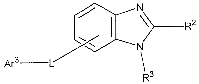
- R is a hydrogen atom, an aryl group having 6 to 60 carbon atoms which may have a substituent, a pyridyl group which may have a substituent, A good quinolyl group, an alkyl group having 1 to 20 carbon atoms which may have a substituent or an alkoxy group having 1 to 20 carbon atoms which may have a substituent, and n is an integer of 0 to 4 And
- R 1 is an aryl group having 6 to 60 carbon atoms which may have a substituent, a pyridyl group which may have a substituent, a quinolyl group which may have a substituent, and a substituent An alkyl group having 1 to 20 carbon atoms or an alkoxy group having 1 to 20 carbon atoms, which may be present;
- R 2 and R 3 each independently have a hydrogen atom, an aryl group having 6 to 60 carbon atoms which may have a substituent, a pyridyl group which may have a substituent, and a substituent
- L represents an arylene group having 6 to 60 carbon atoms which may have a substituent, a pyridinylene group which may have a substituent, a quinolinylene group which may have a substituent or a group having a substituent.
- a fluorenylene group which may be
- a r 1 is an arylene group having 6 to 60 carbon atoms which may have a substituent, a pyridinylene group which may have a substituent or a quinolinylene group which may have a substituent,
- Ar 2 represents an aryl group having 6 to 60 carbon atoms which may have a substituent, a pyridyl group which may have a substituent, a quinolyl group which may have a substituent, a substituent An alkyl group having 1 to 20 carbon atoms which may have a carbon atom or an alkoxy group having 1 to 20 carbon atoms which may have a substituent.
- Ar 3 represents an aryl group having 6 to 60 carbon atoms which may have a substituent, a pyridyl group which may have a substituent, a quinolyl group which may have a substituent, a substituent
- the present invention also provides a material for an organic EL device comprising the nitrogen-containing heterocyclic derivative of the present invention.
- the present invention provides an organic EL device having at least one organic compound layer including a light-emitting layer sandwiched between a pair of electrodes, wherein the nitrogen-containing heterocyclic derivative of the present invention is provided by the organic compound
- An object of the present invention is to provide an organic EL device containing at least one of the layers.
- BEST MODE FOR CARRYING OUT THE INVENTION The nitrogen-containing heterocyclic derivative of the present invention (hereinafter sometimes referred to as the compound of the present invention) is represented by the aforementioned general formula (1), (U) or ( ⁇ ⁇ ).
- R represents a hydrogen atom, an aryl group having 6 to 60 carbon atoms which may have a substituent, a pyridyl group which may have a substituent, A quinolyl group which may have a substituent, an alkyl group having 1 to 20 carbon atoms which may have a substituent or an alkoxy group having 120 carbon atoms which may have a substituent; is there.
- the aryl group having 6 to 60 carbon atoms is preferably an aryl group having 6 to 40 carbon atoms, more preferably an aryl group having 6 to 20 carbon atoms, specifically, a phenyl group and a naphthyl group.
- the alkyl group having 1 to 20 carbon atoms is preferably an alkyl group having 1 to 6 carbon atoms, specifically, other groups such as a methyl group, an ethyl group, a propyl group, a butyl group, a pentyl group, and a hexyl group. And haloalkyl groups such as trifluoromethyl group. Those having 3 or more carbon atoms may be linear, cyclic or branched.
- an alkoxy group having 1 to 20 carbon atoms an alkoxy group having 1 to 6 carbon atoms is preferable.
- each group represented by R examples include a halogen atom, an alkyl group having 1 to 20 carbon atoms which may have a substituent, and an alcohol having 1 to 20 carbon atoms which may have a substituent.
- halogen atom examples include fluorine, chlorine, bromine and iodine.
- alkyl group having 1 to 20 carbon atoms examples include the same as described above.
- alkoxy group having 1 to 20 carbon atoms examples include the same as described above.
- aryl group having 6 to 40 carbon atoms examples include the same as described above.
- Examples of the aryloxy group having 6 to 40 carbon atoms include a phenoxy group and a biphenyloxy group.
- heteroaryl group having 3 to 40 carbon atoms examples include a pyrrolyl group, a furyl group, a phenyl group, a silylyl group, a pyridyl group ', a quinolyl group, an isoquinolyl group, a benzofuryl group, an imidazolyl group, and a pyrimidyl group. And a carbazolyl group, a selenophenyl group, an oxaziazolyl group, a triazolyl group and the like.
- n is an integer of 0-4, preferably 0-2.
- R 1 is an aryl group having 6 to 60 carbon atoms which may have a substituent, a pyridyl group which may have a substituent, or a group which may have a substituent.
- preferred carbon numbers and substituents of each of these groups are the same as those described for R above.
- R 2 and R 3 each independently represent a hydrogen atom, an aryl group having 6 to 60 carbon atoms which may have a substituent, or a substituent.
- L represents an arylene group having 6 to 60 carbon atoms which may have a substituent, a pyridinylene group which may have a substituent, or a group having a substituent.
- arylene group having 6 to 60 carbon atoms an arylene group having 6 to 40 carbon atoms is preferable, and an arylene group having 6 to 20 carbon atoms is more preferable.
- examples thereof include a divalent group formed by removing one hydrogen atom from the aryl group described for R.
- the substituents of each group represented by L are the same as those described for R above.
- a r 1 is have carbon atoms which may have a substituent group 6-6 0 Ariren group which may have a substituent pyridinylene group or a substituted group Is a good quinolinylene group.
- the substituents on each group represented by A r ′ and A r 3 are the same as those described for R above.
- a r 1 is of selected from the condensed ring groups represented by the following general formula (1) to (1 0)
- each condensed ring may be a halogen atom, an alkyl group having 1 to 20 carbon atoms which may have a substituent or a substituent.
- a bonding group consisting of a heterocyclic group having 3 to 40 carbon atoms which may have a substituent may be bonded, and when there are a plurality of bonding groups, the bonding groups are the same or different. It may be. Specific examples of each of these groups include the same as described above.
- J is a single bond or
- Formula indicated by A r 1 (3) is preferably a fused ring group represented by the following general formula (1 1) - (2 5).
- each condensed ring may be a halogen atom, an alkyl group having 1 to 20 carbon atoms which may have a substituent or a substituent.
- Good carbon numbers To 20 alkoxy groups, optionally substituted aryloxy groups having 6 to 40 carbon atoms, optionally substituted aryl groups having 6 to 40 carbon atoms or substituted
- a bonding group consisting of a heteroaryl group having 3 to 40 carbon atoms which may have a group may be bonded, and when there are a plurality of bonding groups, the bonding groups may be the same or different from each other. Good. Specific examples of each of these groups include the same as described above.
- Ar 2 represents an aryl group having 6 to 60 carbon atoms which may have a substituent, a pyridyl group which may have a substituent, or a substituent which may have a substituent.
- Ar 3 represents an aryl group having 6 to 60 carbon atoms which may have a substituent, a pyridyl group which may have a substituent, An optionally substituted quinolyl group, an alkyl group having 1 to 20 carbon atoms which may have a substituent, an alkoxy group having 1 to 20 carbon atoms which may have a substituent, or —Ar′—Ar 2 (Ar 1 and Ar z are the same as those described above). Specific examples, preferred carbon numbers and substituents of these groups are the same as those described for R above.
- Ar 3 is preferably any group selected from the condensed ring groups represented by the following general formulas (21) to (30).
- each fused ring is a halogen atom, an alkyl group having 1 to 20 carbon atoms which may have a substituent, An alkoxy group having 1 to 20 carbon atoms which may have a group, an aryloxy group having 6 to 40 carbon atoms which may have a substituent, and 6 carbon atoms which may have a substituent
- a bonding group consisting of a heteroaryl group having 3 to 40 carbon atoms which may have a substituent or a aryl group of from 40 to 40 may be bonded, and when there are a plurality of bonding groups, the bonding groups are mutually bonded. They may be the same or different. Specific examples of each of these groups include the same as described above. In the general formula (30), the same is the same as the above.
- R ′ represents a hydrogen atom or a substituent.
- Formula indicated by A r 3 (23) is preferably a fused ring group represented by the following general formula (4 1) to (63).
- each fused ring is a halogen atom, an alkyl group having 1 to 20 carbon atoms which may have a substituent or a carbon atom which may have a substituent.
- 682 Alkoxy group having 1 to 20 primes, aryl group having 6 to 40 carbon atoms which may have a substituent, aryl group having 6 to 40 carbon atoms which may have a substituent
- a bonding group consisting of a heteroaryl group having 3 to 40 carbon atoms which may have a substituent may be bonded, and when there are a plurality of bonding groups, the bonding groups are the same or different. May be. Specific examples of each of these groups include the same as described above. R 'is the same as above.
- Ar 2 and ⁇ ⁇ 3 are each independently
- HAr is represented by the general formulas (I) to ( ⁇ ).
- (1-1-1), (1-1-5), (1-7), (2-1), (3-1), (4-2), (4-6) , (7-2), (7-7), (7-8), (7-9) and (9-7) are preferred.
- novel nitrogen-containing heterocyclic derivative represented by the above general formula (I), (II) or (1H) of the present invention is preferably used as a material for an organic EL device.
- the nitrogen-containing heterocyclic derivative of the present invention is preferably used for a light-emitting band, a light-emitting layer, and / or an electron transport layer (electron injection layer) of an organic EL device.
- the nitrogen-containing heterocyclic derivative of the present invention is preferably used as an electron injection material and / or an electron transport material.
- the layer containing the electron injecting material and / or the electron transporting material contains a reducing dopant.
- the emission band represents the entire portion containing a light emitting material that emits light when an electric field is applied to the organic EL element.
- an organic EL device generally has a structure in which thin films made of materials having different functions and roles are stacked, and a light emitting material is often contained only in an organic thin film layer called a light emitting layer.
- the light emitting layer corresponds to a light emitting band. The light emitting layer, the electron transport layer, and the electron injection material will be described later.
- the organic EL device of the present invention is an organic EL device having at least one organic compound layer including a light-emitting layer sandwiched between a pair of electrodes, wherein the general formula (I), (I) At least one of the nitrogen-containing heterocyclic derivatives represented by II) and ( ⁇ ) is contained in at least one of the organic compound layers.
- At least one of the organic compound layers contains the above-mentioned compound of the present invention.
- Anode / hole injection layer / light-emitting layer / electron injection layer / cathode type Anode / light-emitting layer / electron injection layer / cathode type
- the compound of the present invention is preferably used as a material constituting a light emitting layer and / or an electron injection layer.
- a hole injection layer and an electron injection layer are not necessarily required, but a device having these layers has an advantage of improving light emission performance.
- the hole injection layer, the light emitting layer, and the electron injection layer may be sandwiched between a pair of electrodes.
- a mixed layer may be formed using a binder such as a polymer compound in order to make each component exist stably.
- the organic EL device of the present invention will be described by taking an anode / hole injection layer / light emitting layer / electron injection layer / cathode type as an example.
- the organic EL device of the present invention is preferably supported on a substrate.
- the substrate is not particularly limited, and may be any substrate conventionally used in organic EL devices.
- a substrate made of glass, transparent plastic, quartz, or the like can be used.
- the anode in this organic EL device a material having a large work function (4 eV or more), such as a metal, an alloy, an electrically conductive compound, and a mixture thereof is preferably used.
- a metal such as A u, C ul, ITO. S n 0 2, Z n conductive transparent material such as O and the like.
- the anode can be manufactured by forming a thin film from these electrode substances by a method such as vapor deposition or sputtering. When light is extracted from the anode side, the transmittance is desirably greater than 10%, and the sheet resistance as an electrode is preferably several hundreds ⁇ / port or less. Further, although the thickness of the anode depends on the material, it is usually selected in the range of 10 nm to 1 ⁇ m, preferably in the range of 10 to 200 nm.
- the cathode metals, alloys, and electrically conductive compounds with a low work function (4 eV or less) And a mixture thereof as an electrode material.
- the electrode substance include sodium, Natoriumu Ichiriki Riumu alloy, magnesium, Ma Guneshiumu Ichigin alloy, lithium, Maguneshiumu / copper mixtures V Maguneshiumu Ichi Inn Jiumu alloy, A 1 / AI 2 0 3 , indium, Aluminum-lithium alloy and the like can be mentioned.
- the cathode can be manufactured by forming a thin film from these electrode substances by a method such as evaporation or sputtering.
- the sheet resistance as an electrode is preferably several hundreds ⁇ / b or less, and the film thickness is generally selected in the range of 10 to 50 O nm, preferably 50 to 20 O nm.
- the luminous efficiency is advantageously improved.
- the present invention compound As the light emitting material constituting the light emitting layer in the organic EL device of the present invention, it is preferable to use the present invention compound.
- the compound of the present invention may be used alone, or may be used together with a known light emitting material.
- the compound of the present invention is used for a material other than the light-emitting layer, the light-emitting material of the light-emitting layer is not particularly limited, and any one of conventionally known light-emitting materials can be used. it can.
- luminescent materials include polycyclic fused aromatic compounds, benzoxazole-based, benzothiazole-based, benzoimidazole-based fluorescent brighteners, metal-chelated oxanoide compounds, and distyrylbenzene-based compounds.
- a compound having good thin film formation properties can be used.
- the polycyclic fused aromatic compound for example, an anthracene, a naphthalene, a phenanthrene, a pyrene, a chrysene, a condensed ring light-emitting substance having a perylene skeleton, and other condensed rings containing about eight condensed rings Light-emitting substances and the like can be given.
- the light-emitting layer may be composed of one or more of these light-emitting materials, or may be a laminate of light-emitting layers made of a different kind of compound from the light-emitting layer.
- the hole injection layer in the organic EL device of the present invention is made of a hole transporting compound and has a function of transmitting holes injected from the anode to the light emitting layer. By intervening between the light emitting layer and the light emitting layer, many holes are injected into the light emitting layer by applying a lower electric field.
- the hole transport compound used in such a hole injection layer is disposed between two electrodes to which an electric field is applied, and appropriately emits holes when holes are injected from the anode. are those that can reach transfer to the layer, for example, it is preferable to have a 1 0 4 to 1 0 6 V / cm of 1 0 6 also reduced when an electric field is applied cm 2 / V ⁇ sec hole mobility .
- the hole transporting compound is not particularly limited as long as it has the above-mentioned preferable properties.
- a material commonly used as a hole charge injection / transport material, or an organic EL device Any of the known materials used for the hole injection layer can be selected and used.
- Examples of the hole transfer compound include copper phthalocyanine, N, N, N ′, N′-tetraphenyl-1,4,4′-diaminophenyl, ⁇ , ⁇ , diphenyl, ⁇ , ⁇ , di (3-methylphenyl).
- a crystalline or amorphous material of an inorganic semiconductor such as Si, SiC, and CdS can also be used.
- the hole injection layer may be composed of one or more of these hole injection materials, or may be a hole injection layer made of a compound different from the hole injection layer. They may be stacked.
- the electron injection layer in the organic EL device of the present invention is made of an electron injection material, and has a function of transmitting electrons injected from the cathode to the light emitting layer.
- the compound of the present invention is preferably used as an electron injection material.
- the electron injecting material is not particularly limited, and any one of conventionally known electron injecting material compounds may be used. it can.
- the organic EL device of the present invention there is a device containing a reducing dopant in a region for transporting electrons or an interface region between the cathode and the organic compound layer.
- an organic EL device containing a reducing dopant in the compound of the present invention is preferable.
- the reducing property is defined as a substance capable of reducing an electron transporting compound. Therefore, various substances having a certain reducing property can be used.
- the substance is at least one substance selected from the group consisting of:
- a preferable reducing dopant preferably has a work function of 2.9 eV or less, and more specifically, Na (work function: 2.36 eV) and K (work function: 2.2). 8 e V), one or more alkali metals selected from the group consisting of R b (work function: 2.16 e V) and C s (work function: 1.95 e V), It is selected from the group consisting of C a (work function: 2.9 eV), S r (work function: 2.0 to 2.5 eV), and B a (work function: .52 eV).
- R b work function: 2.16 e V
- C s work function: 1.95 e V
- more preferred reducing dopants are one or more alkali metal selected from the group consisting of K, Rb and Cs, and more preferably Rb or Cs. Yes, most preferred is Cs.
- alkali metals have particularly high reducing ability, and by adding a relatively small amount to the electron injection region, it is possible to achieve an improvement in the emission luminance and a long life of the organic EL device.
- a reducing dopant with a work function of 2.9 eV or less Combinations of alkali metals are also preferable, and in particular, combinations containing Cs, for example, Cs and Na, Cs and K, Cs and Rb, or Cs, Na and ⁇ ⁇ ⁇ ⁇ are preferable.
- the reducing ability can be efficiently exhibited, and by adding the compound to the electron injection region, the improvement of the emission luminance and the extension of the life of the organic EL device can be achieved.
- the alkali metal one or more selected from the group consisting of alkali metal halides, alkaline earth metal chalcogenides, alkali metal halides, and alkaline earth metal halides. The same effect can be obtained by using a metal compound, and the same effect can be obtained by using an alkali metal organic complex or an alkaline earth metal organic complex.
- an electron injection layer composed of an insulator, a semiconductor, or an inorganic compound may be further provided between the cathode and the organic layer.
- an insulator include one or more metal compounds selected from the group consisting of alkali metal chalcogenides, alkaline earth metal chalcogenides, alkali metal halides and alkaline earth metal halides. It is preferred to use. It is preferable that the electron injection layer is composed of these metal compounds, since the electron injection property can be further improved.
- Preferred alkaline earth metal chalcogenides include, for example, Ca ⁇ , BaO, SrO, Be ⁇ , Bas and CaSe.
- Preferred alkali metal halides include, for example, 'LiF, NaF, KF, LiC1, KC1, and NaC1.
- Preferable halides of Al force Li earth metals for example, fluorides and the like CaF 2, BaF 2, SrF 2 , Mg F 2 and B e F 2, and halides other than fluorides.
- the semiconductor constituting the electron injection layer includes a group consisting of Ba, Ca, Sr, Yb, A1, Ga, In, Li, Na, Cd, Mg, Si, Ta, Sb, and Zn.
- the inorganic compound constituting the electron injection layer is preferably a microcrystalline or amorphous insulating thin film. If the electron injection layer is composed of these inorganic compounds, a more uniform thin film can be formed, and thus, pixel defects such as dark spots can be reduced. Examples of such inorganic compounds include the above-described alkali metal chalcogenides, alkaline earth metal chalcogenides, halides of alkali metals, and halides of alkaline earth metals.
- the electron injection layer in the organic EL device of the present invention is formed by forming the compound of the present invention or another electron injection material by a known thinning method such as a vacuum evaporation method, a spin coating method, a casting method, and an LB method. Can be formed.
- the thickness of the electron injection layer is not particularly limited, but is usually 5 nm to 5 nm.
- This electron injection layer may be composed of one layer of one or more of these electron injection materials, or may be a laminate of two or more electron injection layers of another compound. Is also good.
- a hole injection material made of inorganic P-type Si, p-type SiC, and an electron-injected material made of n-type a-Si, n-type ⁇ -SiC are used for forming the electron injection layer. It can be used as an electron injection material.
- an inorganic semiconductor disclosed in International Patent Publication No. W090 / 09998 can be mentioned.
- a method for manufacturing the organic EL device of the present invention will be described.
- a method for producing the above-described anode / hole injection layer / light-emitting layer / electron injection layer / cathode type organic EL device will be described.
- a thin film composed of a desired electrode material for example, a material for an anode, is deposited on a suitable substrate by a method such as vapor deposition or sputtering so as to have a thickness of 1 or less, preferably 10 to 20 nm.
- a method for producing the above-described anode / hole injection layer / light-emitting layer / electron injection layer / cathode type organic EL device will be described.
- a thin film composed of a desired electrode material for example, a material for an anode
- a suitable substrate by a method such as vapor deposition or sputtering so as to have a thickness of 1 or less, preferably 10 to 20 nm.
- a hole injection layer, a light-emitting layer, and an electron injection layer, which are EL element components, are sequentially laminated on this to form a thin film made of each constituent material.
- the thin film forming method used here include the spin coating method, the casting method, and the vapor deposition method as described above.
- the vacuum evaporation method is preferred because a uniform film is easily obtained and pinholes are hardly generated.
- the deposition conditions vary depending on the type of compound used, the target crystal structure of the molecular deposition film, the association structure, and the like. 4 0 0 T :, vacuum 1 0- 6 ⁇ 1 0- 3 P a, deposition rate 0.
- a thin film having a thickness of 1 or less, preferably 50 to 200 nm, made of a material for a cathode is formed thereon by, for example, a method such as evaporation or sputtering. By doing so, a desired organic EL device can be obtained.
- the production order can be reversed, and the cathode, the electron injection layer, the light emitting layer, the hole injection (transport) layer, and the anode can be produced in this order.
- anode / light-emitting layer / cathode type organic EL element in which a hole injection layer, a light-emitting layer, and an electron injection layer are interposed between a pair of electrodes
- a thin film made of a material for an anode is formed on a substrate, and a hole injecting material, a light emitting material, an electron injecting material, and a binding of polyvinyl carbazole, polycarbonate, polyacrylate, polyester, and polyether, etc.
- a thin film made of a material for a cathode is formed on a light emitting layer (or a light emitting band) by forming a thin film from the force of applying a solution containing an agent or the like or by dip coating from this solution.
- a thin film made of a cathode material may be formed thereon.
- the organic EL device of the present invention is characterized in that the nitrogen-containing heterocyclic derivative of the present invention comprises an organic compound layer, When used for the electron injection layer, the adhesion between the organic compound layer containing the compound of the present invention and an electrode (particularly, a cathode) is improved.
- This benzamide was heated and stirred at about 300 ° C. for 30 minutes under reduced pressure (about 20 mmHg). After completion of the reaction, the residue was dissolved in dichloromethane and purified by silica gel column chromatography to obtain 3.5 g (80% yield) of 2- (4-promophenyl) -tophenyl-1H-benzoimidazole.
- the obtained mixture (llg (31 mol)) and p-toluenesulfonic acid monohydrate (1.75 g, 9 mmol) were dispersed in xylene (100 ml), and the mixture was heated under reflux for 7 hours. After the completion of the reaction, the mixture was allowed to cool, a 5% aqueous potassium carbonate solution and toluene were added, and the organic layer was extracted. The organic layer was washed with a 5% aqueous carbonated solution, water, and brine, and dried over sodium sulfate.
- 2,5-Dibromonitrobenzene 10 (35.611111101), 8.8 g (107 ol) of sodium acetate and 6.6 g (71 rnmol) of aniline were heated and stirred at 160 t for 9 hours in a nitrogen atmosphere.
- the reaction solution was cooled to room temperature, diluted with ethyl acetate, and filtered. The filtrate was concentrated and purified by silica gel column chromatography to obtain 9.9 g (yield 63%) of 4-bromo-2-nitrodiphenylamine.
- N- [2- (4-bromophenylamino) phenyl] benzamide (2.lg, 5.7 mmol) obtained in (2) was suspended in 30 milliliters of xylene, and p-toluenesulfone was added. Acid monohydrate 0.6 (2.911111101) was added, and azeotropic dehydration was performed while heating and refluxing for 3 hours. After cooling, ethyl acetate, methylene chloride and water were added to the reaction solution, and the insolubles were filtered off. The organic layer was extracted from the mother liquor, washed with water and saturated saline, dried over anhydrous sodium sulfate, and the solvent was distilled off under reduced pressure. The residue was purified by silica gel column chromatography to give tri (4-bromophenyl) -2-phenyl-1H-benzimidazole l.Og as slightly pink white crystals (yield 52%).
- 6-Bromopicolinic acid Suspension of lg (25 mmol) in 70 ml of 1,2-dichloroethane, addition of 4.2 g (35 mmol) of thionyl chloride, and addition of 3 drops of N, N-dimethylformamide Heated to reflux for 4 hours. After completion of the reaction, the solvent was distilled off under reduced pressure to obtain 6-bromopicolinoyl chloride.
- the selected phenylenediamine was dissolved in 150 ml of ethyl acetate, and the extracted organic layer was added with pyridine 3.
- Og 38 countries 01
- DMAP 4-dimethylaminopyridine
- the amount of the catalyst was added, and the mixture was stirred at room temperature for 3 hours and left for 1 hour. After completion of the reaction, water was added, and the precipitated solid was separated by filtration and sufficiently washed with water and methanol to obtain 4.lg (yield 49%) of benzamide as a white solid.
- 5-bromo-1-methyl-2-phenyl-1H-benzimidabul 1.5 g (5.6 mmol) obtained in (4), 10-naphthalene-2-yl-anthracene-9-boronic acid 2.3 g (5.6 mmol) and 0.12 g (0.1 mmol) of tetrakis (triphenylphosphine) palladium are dissolved in 60 ml of 1,2-dimethoxetane, and 30 ml of a 2.0 M sodium carbonate aqueous solution is dissolved. A little was added, and the mixture was heated and refluxed for 8 hours under an argon atmosphere.
- a 25 mm X 75 mm XL 1-thick glass substrate with an ITQ transparent electrode (manufactured by Geomatic) was subjected to ultrasonic cleaning in isopropyl alcohol for 5 minutes, and then UV ozone cleaning for 30 minutes.
- the glass substrate with the transparent electrode lines after cleaning is mounted on a substrate holder of a vacuum deposition apparatus. First, on the surface on the side where the transparent electrode lines are formed, cover the transparent electrodes with N, having a thickness of 60 nm.
- NPD232 film N'-bis (N, N'-diphenyl-4-aminophenyl) -N, N-diphenyl-4,4, -diamino-1 ,,-biphenyl film (hereinafter abbreviated as "TPD232 film”) was formed by resistance heating evaporation.
- This TPD232 film functions as a hole injection layer.
- a 4,4′-bis [N- (1-naphthyl) -N-phenylamino] biphenyl film (hereinafter abbreviated as “NPD film”) having a thickness of 20 nm was formed by resistance heating evaporation. Filmed.
- NPD film functions as a hole transport layer.
- DPVDPAN 4 "-bis (2,2-diphenylvinyl) -9,10-diphenylanthracene (hereinafter abbreviated as" DPVDPAN ”) having a thickness of 40 nm is formed on the NPD film by resistance heating evaporation. Filmed. This DPVDPAN film functions as a light emitting layer. On this DPVDPAN film, a compound (1-7) with a film thickness of lOnra was formed by vapor deposition. This compound (117) film functions as an electron injection layer.
- the compound (1-7) and Li are binary-deposited to form a compound (1-7): Li film at a deposition rate of 1.5 A / sec: 1 An electron injection layer (or cathode) with a thickness of lOnra was formed at A / min.
- An organic EL device was fabricated in the same manner as in Example 1, except that the compound (4-2) was used instead of the compound (1-7).
- 25mraX75mmXL lmm thick glass substrate with ITO transparent electrode (manufactured by Geomatic) is subjected to ultrasonic cleaning in isopropyl alcohol for 5 minutes, followed by UV ozone cleaning. Purification is 30 minutes ⁇ 1
- the cleaned glass substrate with the transparent electrode lines is mounted on the substrate holder of the vacuum evaporation system.
- a 60 nm-thick TPD is placed on the side where the transparent electrode lines are formed so as to cover the transparent electrodes.
- 232 films were formed by resistance heating evaporation.
- This TPD232 film functions as a hole injection layer.
- An NPD film having a thickness of 20 nm was formed on the TPD232 film by resistance heating evaporation. This NPD film functions as a hole transport layer.
- a styryl derivative D PVD PAN and the following styrylamine derivative S1 are deposited at a film ratio of 40: 2 on the NPD film at a film thickness of 40 nm. It was formed into a blue light emitting layer.
- a compound described in Table 1 was formed into a film having a thickness of 20 nm as an electron transporting layer. Thereafter, LiF (Li source: manufactured by Saesgetter Co., Ltd.) was deposited to a thickness of l nm.
- Metal A1 was deposited on this thin film to a thickness of 150 nm to form a metal cathode, thereby producing an organic EL device.
- Comparative Example 1 An organic EL device was produced in the same manner as in Example 1, except that A 1 q (aluminum complex of 8-hydroxyquinoline) was used instead of the compound (1-7).
- An organic EL device was produced in the same manner as in Example 1, except that the following compound A described in US Pat. No. 5,645,98 was used instead of the compound (117).
- An organic EL device was produced in the same manner as in Example 1, except that the following compound B described in JP-A-2002-38141 was used instead of the compound (117).
- high emission luminance can be obtained at a low voltage, and a compound in which an alkyl group or a pyridyl group is introduced into R 1 , R 2 or R 3 of the general formulas (I) to ( ⁇ ) is used for the electron transport layer
- the device also achieved high light emission luminance at low voltage.
- an organic EL device having high light emission luminance and light emission efficiency at a low voltage is obtained. can get.
Abstract
Description


Claims


Priority Applications (7)
| Application Number | Priority Date | Filing Date | Title |
|---|---|---|---|
| EP10152089.8A EP2174933B1 (en) | 2003-03-13 | 2004-01-27 | Benzimidazole derivatives for use in organic electroluminescent devices |
| JP2005503458A JP4185097B2 (en) | 2003-03-13 | 2004-01-27 | Novel nitrogen-containing heterocyclic derivative and organic electroluminescence device using the same |
| EP04705503.3A EP1602648B1 (en) | 2003-03-13 | 2004-01-27 | Nitrogen-containing heterocycle derivative and organic electroluminescent element using the same |
| US10/547,312 US7851071B2 (en) | 2003-03-13 | 2004-01-27 | Nitrogen-containing heterocycle derivative and organic electroluminescent element using the same |
| CN200480012355.7A CN1784388B (en) | 2003-03-13 | 2004-01-27 | Nitrogen-containing heterocyclic derivative and organic electroluminescent element using same |
| EP10152087.2A EP2174932B1 (en) | 2003-03-13 | 2004-01-27 | Nitrogen-containing heterocycle derivative and organic electroluminescent element using the same |
| US12/662,251 US8097349B2 (en) | 2003-03-13 | 2010-04-07 | Nitrogen containing heterocycle derivative and organic electroluminescent element using the same |
Applications Claiming Priority (2)
| Application Number | Priority Date | Filing Date | Title |
|---|---|---|---|
| JP2003067847 | 2003-03-13 | ||
| JP2003-67847 | 2003-03-13 |
Related Child Applications (2)
| Application Number | Title | Priority Date | Filing Date |
|---|---|---|---|
| US10/547,312 A-371-Of-International US7851071B2 (en) | 2003-03-13 | 2004-01-27 | Nitrogen-containing heterocycle derivative and organic electroluminescent element using the same |
| US12/662,251 Continuation US8097349B2 (en) | 2003-03-13 | 2010-04-07 | Nitrogen containing heterocycle derivative and organic electroluminescent element using the same |
Publications (1)
| Publication Number | Publication Date |
|---|---|
| WO2004080975A1 true WO2004080975A1 (en) | 2004-09-23 |
Family
ID=32984572
Family Applications (1)
| Application Number | Title | Priority Date | Filing Date |
|---|---|---|---|
| PCT/JP2004/000682 WO2004080975A1 (en) | 2003-03-13 | 2004-01-27 | Nitrogen-containing heterocycle derivative and organic electroluminescent element using the same |
Country Status (7)
| Country | Link |
|---|---|
| US (2) | US7851071B2 (en) |
| EP (3) | EP2174933B1 (en) |
| JP (3) | JP4185097B2 (en) |
| KR (3) | KR101020350B1 (en) |
| CN (3) | CN101812021B (en) |
| TW (3) | TWI363054B (en) |
| WO (1) | WO2004080975A1 (en) |
Cited By (163)
| Publication number | Priority date | Publication date | Assignee | Title |
|---|---|---|---|---|
| WO2005097756A1 (en) * | 2004-04-07 | 2005-10-20 | Idemitsu Kosan Co., Ltd. | Nitrogenous heterocycle derivative and organic electroluminescent element employing the same |
| JP2005289921A (en) * | 2004-04-01 | 2005-10-20 | Mitsui Chemicals Inc | Anthracene compound and organic electroluminescent element containing the compound |
| WO2006127315A2 (en) * | 2005-05-25 | 2006-11-30 | Eastman Kodak Company | Oled-electron transporting layer |
| WO2007007464A1 (en) * | 2005-07-11 | 2007-01-18 | Idemitsu Kosan Co., Ltd. | Nitrogen-containing heterocyclic derivative and organic electroluminescence element using the same |
| WO2007007463A1 (en) * | 2005-07-11 | 2007-01-18 | Idemitsu Kosan Co., Ltd. | Nitrogen-containing heterocyclic derivative having electron-attracting substituent and organic electroluminescence element using the same |
| JP2007039633A (en) * | 2005-06-30 | 2007-02-15 | Shinichiro Isobe | Marking agent |
| WO2007018007A1 (en) * | 2005-08-05 | 2007-02-15 | Idemitsu Kosan Co., Ltd. | Nitrogenous heterocyclic derivative and organic electroluminescence device making use of the same |
| WO2007052759A1 (en) * | 2005-11-07 | 2007-05-10 | Idemitsu Kosan Co., Ltd. | Organic electroluminescent element |
| WO2007061063A1 (en) * | 2005-11-28 | 2007-05-31 | Idemitsu Kosan Co., Ltd. | Organic electroluminescent device |
| WO2007063993A1 (en) | 2005-12-02 | 2007-06-07 | Idemitsu Kosan Co., Ltd. | Nitrogenous heterocyclic derivative and organic electroluminescence device making use of the same |
| WO2007099983A1 (en) * | 2006-02-28 | 2007-09-07 | Idemitsu Kosan Co., Ltd. | Organic electroluminescent device using fluoranthene derivative and indenoperylene derivative |
| WO2007099802A1 (en) * | 2006-02-23 | 2007-09-07 | Idemitsu Kosan Co., Ltd. | Red organic electroluminescence element |
| WO2007099872A1 (en) * | 2006-02-23 | 2007-09-07 | Idemitsu Kosan Co., Ltd. | Organic electroluminescent device |
| WO2007111262A1 (en) | 2006-03-27 | 2007-10-04 | Idemitsu Kosan Co., Ltd. | Nitrogen-containing heterocyclic derivative and organic electroluminescent device using same |
| WO2007111263A1 (en) | 2006-03-27 | 2007-10-04 | Idemitsu Kosan Co., Ltd. | Nitrogen-containing heterocyclic derivative and organic electroluminescent device using same |
| WO2007132678A1 (en) * | 2006-05-11 | 2007-11-22 | Idemitsu Kosan Co., Ltd. | Organic electroluminescent device |
| WO2008015949A1 (en) * | 2006-08-04 | 2008-02-07 | Idemitsu Kosan Co., Ltd. | Organic electroluminescence device |
| JP2008094777A (en) * | 2006-10-13 | 2008-04-24 | Mitsui Chemicals Inc | Anthracene compound and organic light emitting device containing the compound |
| WO2008062773A1 (en) * | 2006-11-20 | 2008-05-29 | Idemitsu Kosan Co., Ltd. | Organic electroluminescent device |
| WO2008102740A1 (en) | 2007-02-19 | 2008-08-28 | Idemitsu Kosan Co., Ltd. | Organic electroluminescent device |
| WO2008105294A1 (en) | 2007-02-28 | 2008-09-04 | Idemitsu Kosan Co., Ltd. | Organic el device |
| WO2008111553A1 (en) * | 2007-03-09 | 2008-09-18 | Idemitsu Kosan Co., Ltd. | Organic el device and display |
| WO2008129912A1 (en) | 2007-04-12 | 2008-10-30 | Tosoh Corporation | Phenyl-substituted 1,3,5-triazine compound, process for producing the same, and organic electroluminescent device containing the same as component |
| JP2009004761A (en) * | 2007-05-21 | 2009-01-08 | Sony Corp | Organic electroluminescent device and display apparatus |
| JP2009514812A (en) * | 2005-10-21 | 2009-04-09 | エルジー・ケム・リミテッド | Novel binaphthalene derivative, method for producing the same, and organic electronic device using the same |
| JP2009524653A (en) * | 2006-01-27 | 2009-07-02 | エルジー・ケム・リミテッド | NOVEL ANTHRACENE DERIVATIVE, PROCESS FOR PRODUCING THE SAME AND ORGANIC ELECTRIC ELEMENT USING THE SAME |
| WO2009081857A1 (en) * | 2007-12-21 | 2009-07-02 | Idemitsu Kosan Co., Ltd. | Organic electroluminescent device |
| WO2009084543A1 (en) | 2007-12-27 | 2009-07-09 | Idemitsu Kosan Co., Ltd. | Nitrogen-containing heterocyclic derivative and organic electroluminescent device using the same |
| WO2009084544A1 (en) * | 2007-12-27 | 2009-07-09 | Idemitsu Kosan Co., Ltd. | Nitrogen-containing heterocyclic derivative and organic electroluminescent device using the same |
| US20090206736A1 (en) * | 2006-05-11 | 2009-08-20 | Idemitsu Kosan Co., Ltd. | Organic electroluminescence element |
| WO2010038854A1 (en) | 2008-10-03 | 2010-04-08 | 東ソー株式会社 | 1,3,5-triazine derivative, process for producing same, and organic electroluminescent element comprising same as constituent component |
| WO2010041605A1 (en) * | 2008-10-06 | 2010-04-15 | ソニー株式会社 | Organic electroluminescent element and display device |
| JP2010118591A (en) * | 2008-11-14 | 2010-05-27 | Konica Minolta Holdings Inc | Organic electroluminescent element, display device, illuminating device and organic electroluminescent element material |
| JPWO2008111554A1 (en) * | 2007-03-09 | 2010-06-24 | 出光興産株式会社 | Organic EL element and display device |
| DE102009005746A1 (en) | 2009-01-23 | 2010-07-29 | Merck Patent Gmbh | Materials for organic electroluminescent devices |
| WO2010094378A1 (en) | 2009-02-17 | 2010-08-26 | Merck Patent Gmbh | Organic electronic device |
| WO2010102706A1 (en) | 2009-03-09 | 2010-09-16 | Merck Patent Gmbh | Organic electroluminescence device |
| DE102009014513A1 (en) | 2009-03-23 | 2010-09-30 | Merck Patent Gmbh | Organic electroluminescent device |
| DE102009017064A1 (en) | 2009-04-09 | 2010-10-14 | Merck Patent Gmbh | Organic electroluminescent device |
| WO2010149259A2 (en) | 2009-06-22 | 2010-12-29 | Merck Patent Gmbh | Conducting formulation |
| CN101250405B (en) * | 2008-02-26 | 2011-01-19 | 南京大学 | Novel mercapto fluorescence probe and uses thereof |
| DE102009042680A1 (en) | 2009-09-23 | 2011-03-24 | Merck Patent Gmbh | Organic electroluminescent device |
| WO2011076324A1 (en) | 2009-12-23 | 2011-06-30 | Merck Patent Gmbh | Compositions comprising organic semiconducting compounds |
| WO2011076380A1 (en) | 2009-12-23 | 2011-06-30 | Merck Patent Gmbh | Composition for the preparation of organic electronic (oe) devices |
| WO2011086941A1 (en) | 2010-01-15 | 2011-07-21 | 出光興産株式会社 | Organic electroluminescent element |
| DE102010010481A1 (en) | 2010-03-06 | 2011-09-08 | Merck Patent Gmbh | Organic electroluminescent device |
| WO2011128034A1 (en) | 2010-04-12 | 2011-10-20 | Merck Patent Gmbh | Composition having improved performance |
| WO2011128035A1 (en) | 2010-04-12 | 2011-10-20 | Merck Patent Gmbh | Composition and method for preparation of organic electronic devices |
| WO2011129096A1 (en) | 2010-04-12 | 2011-10-20 | 出光興産株式会社 | Organic electroluminescent element |
| CN101414661B (en) * | 2007-10-17 | 2011-11-16 | 中国科学院理化技术研究所 | Organic electronic transmission and/or positive hole countercheck material, and synthesizing method and purpose thereof |
| WO2011141109A1 (en) | 2010-05-11 | 2011-11-17 | Merck Patent Gmbh | Organic electroluminescent devices |
| WO2011147523A1 (en) | 2010-05-27 | 2011-12-01 | Merck Patent Gmbh | Formulation and method for preparation of organic electronic devices |
| JP2012028764A (en) * | 2010-06-24 | 2012-02-09 | Sony Corp | Organic el display device and method of manufacturing the same |
| US8119814B2 (en) * | 2007-12-07 | 2012-02-21 | Samsung Electronics Co., Ltd. | Aromatic hetrocyclic compound, organic light-emitting diode including organic layer comprising the aromatic hetrocyclic compound, and method of manufacturing the organic light-emitting diode |
| WO2012124642A1 (en) | 2011-03-14 | 2012-09-20 | 出光興産株式会社 | Organic electroluminescent element |
| WO2013022145A1 (en) * | 2011-08-08 | 2013-02-14 | 제일모직 주식회사 | Organic optoelectronic device compound and organic light-emitting element including same |
| DE102012016192A1 (en) | 2011-08-19 | 2013-02-21 | Merck Patent Gmbh | New compounds capable of forming hydrogen bonds are useful in electronic device, e.g. organic electroluminescent device, organic light-emitting transistor and organic light-emitting electrochemical cell |
| WO2013050101A1 (en) | 2011-10-06 | 2013-04-11 | Merck Patent Gmbh | Organic electroluminescent device |
| WO2013050862A1 (en) | 2011-10-07 | 2013-04-11 | ユーディーシー アイルランド リミテッド | Organic electroluminescent element, light emitting material therefor, light emitting device, display device, and illumination device |
| WO2013051234A1 (en) * | 2011-10-04 | 2013-04-11 | ソニー株式会社 | Organic electroluminescent element |
| WO2013064881A2 (en) | 2011-11-02 | 2013-05-10 | ユーディーシー アイルランド リミテッド | Organic electroluminescent element, material for organic electroluminescent element and light emitting device, display device, and illumination device, each employing organic electroluminescent element |
| WO2013072740A2 (en) | 2011-11-15 | 2013-05-23 | ユーディーシー アイルランド リミテッド | Charge-transporting material, organic electroluminescent element, and light-emitting device, display device and illumination device characterised by using said element |
| DE102012022880A1 (en) | 2011-12-22 | 2013-06-27 | Merck Patent Gmbh | Electronic device e.g. organic integrated circuits, organic field-effect transistors, organic thin-film transistors, organic light emitting transistors, comprises an organic layer comprising substituted heteroaryl compounds |
| WO2013108069A2 (en) | 2011-10-06 | 2013-07-25 | ユーディーシー アイルランド リミテッド | Organic electroluminescent element, compound and material for organic electroluminescent element, used in the same, and light emitting device, display device and illumination device, using the element |
| EP2623508A1 (en) | 2012-02-02 | 2013-08-07 | Konica Minolta Advanced Layers, Inc. | Iridium complex compound, organic electroluminescent element material, organic electroluminescent element, illumination device and display device |
| DE102013201846A1 (en) | 2012-02-06 | 2013-08-14 | Udc Ireland Limited | Organic electroluminescence element, useful in a light emitting device, comprises substrate, pair of electrodes comprising anode and cathode, and layer of organic layers comprising light-emitting layer, which is arranged between electrodes |
| WO2013135352A1 (en) | 2012-03-15 | 2013-09-19 | Merck Patent Gmbh | Electronic devices |
| JP2013258379A (en) * | 2012-06-14 | 2013-12-26 | Udc Ireland Ltd | Chemical compound, organic electroluminescent element, and light-emitting device, display device and lighting device that use organic electroluminescent element |
| WO2014030666A1 (en) | 2012-08-24 | 2014-02-27 | コニカミノルタ株式会社 | Transparent electrode, electronic device, and method for manufacturing transparent electrode |
| WO2014067614A1 (en) | 2012-10-31 | 2014-05-08 | Merck Patent Gmbh | Electronic device |
| WO2014082705A1 (en) | 2012-11-30 | 2014-06-05 | Merck Patent Gmbh | Electronic device |
| WO2014106522A1 (en) | 2013-01-03 | 2014-07-10 | Merck Patent Gmbh | Materials for electronic devices |
| WO2014106524A2 (en) | 2013-01-03 | 2014-07-10 | Merck Patent Gmbh | Materials for electronic devices |
| WO2014106523A1 (en) | 2013-01-03 | 2014-07-10 | Merck Patent Gmbh | Electronic device |
| WO2014157494A1 (en) | 2013-03-29 | 2014-10-02 | コニカミノルタ株式会社 | Material for organic electroluminescent elements, organic electroluminescent element, display device and lighting device |
| WO2014157610A1 (en) | 2013-03-29 | 2014-10-02 | コニカミノルタ株式会社 | Organic electroluminescent element, lighting device, display device, light-emitting thin film and composition for organic electroluminescent element, and light-emitting method |
| WO2014157618A1 (en) | 2013-03-29 | 2014-10-02 | コニカミノルタ株式会社 | Organic electroluminescent element, and lighting device and display device which are provided with same |
| US8872423B2 (en) * | 2007-03-07 | 2014-10-28 | Sony Corporation | Organic electroluminescent device and display device |
| WO2015082046A2 (en) | 2013-12-06 | 2015-06-11 | Merck Patent Gmbh | Substituted oxepines |
| WO2015082037A1 (en) | 2013-12-06 | 2015-06-11 | Merck Patent Gmbh | Compositions containing a polymeric binder which comprises acrylic and/or methacrylic acid ester units |
| WO2015165563A1 (en) | 2014-04-30 | 2015-11-05 | Merck Patent Gmbh | Materials for electronic devices |
| WO2015192941A1 (en) | 2014-06-18 | 2015-12-23 | Merck Patent Gmbh | Compositions for electronic devices |
| WO2016119992A1 (en) | 2015-01-30 | 2016-08-04 | Merck Patent Gmbh | Materials for electronic devices |
| WO2016120007A1 (en) | 2015-01-30 | 2016-08-04 | Merck Patent Gmbh | Formulations with a low particle content |
| WO2017008883A1 (en) | 2015-07-15 | 2017-01-19 | Merck Patent Gmbh | Composition comprising organic semiconducting compounds |
| WO2017012694A1 (en) | 2015-07-23 | 2017-01-26 | Merck Patent Gmbh | Phenyl derivatives substituted with at least two electron acceptors and at least two electron donors for use in organic electronic devices |
| WO2017028940A1 (en) | 2015-08-14 | 2017-02-23 | Merck Patent Gmbh | Phenoxazine derivatives for organic electroluminescent devices |
| EP3200255A2 (en) | 2016-01-06 | 2017-08-02 | Konica Minolta, Inc. | Organic electroluminescent element, method for producing organic electroluminescent element, display, and lighting device |
| WO2017133829A1 (en) | 2016-02-05 | 2017-08-10 | Merck Patent Gmbh | Materials for electronic devices |
| DE102017008794A1 (en) | 2016-10-17 | 2018-04-19 | Merck Patent Gmbh | Materials for use in electronic devices |
| WO2018069167A1 (en) | 2016-10-10 | 2018-04-19 | Merck Patent Gmbh | Electronic device |
| WO2018083053A1 (en) | 2016-11-02 | 2018-05-11 | Merck Patent Gmbh | Materials for electronic devices |
| WO2018087020A1 (en) | 2016-11-08 | 2018-05-17 | Merck Patent Gmbh | Compounds for electronic devices |
| WO2018095839A1 (en) | 2016-11-22 | 2018-05-31 | Merck Patent Gmbh | Bridged triarylamines for electronic devices |
| WO2018114882A1 (en) | 2016-12-22 | 2018-06-28 | Merck Patent Gmbh | Materials for electronic devices |
| WO2018141706A1 (en) | 2017-02-02 | 2018-08-09 | Merck Patent Gmbh | Materials for electronic devices |
| WO2018158232A1 (en) | 2017-03-01 | 2018-09-07 | Merck Patent Gmbh | Organic electroluminescent device |
| WO2018157981A1 (en) | 2017-03-02 | 2018-09-07 | Merck Patent Gmbh | Materials for organic electronic devices |
| EP3378857A1 (en) | 2012-11-12 | 2018-09-26 | Merck Patent GmbH | Materials for electronic devices |
| WO2018189134A1 (en) | 2017-04-13 | 2018-10-18 | Merck Patent Gmbh | Composition for organic electronic devices |
| WO2018197447A1 (en) | 2017-04-25 | 2018-11-01 | Merck Patent Gmbh | Compounds for electronic devices |
| WO2018234346A1 (en) | 2017-06-23 | 2018-12-27 | Merck Patent Gmbh | Materials for organic electroluminescent devices |
| WO2018234220A1 (en) | 2017-06-21 | 2018-12-27 | Merck Patent Gmbh | Materials for electronic devices |
| WO2019002198A1 (en) | 2017-06-26 | 2019-01-03 | Merck Patent Gmbh | Homogeneous mixtures |
| WO2019002190A1 (en) | 2017-06-28 | 2019-01-03 | Merck Patent Gmbh | Materials for electronic devices |
| WO2019007825A1 (en) | 2017-07-03 | 2019-01-10 | Merck Patent Gmbh | Organic electroluminescent device |
| WO2019007823A1 (en) | 2017-07-03 | 2019-01-10 | Merck Patent Gmbh | Formulations with a low content of phenol type impurities |
| WO2019007867A1 (en) | 2017-07-05 | 2019-01-10 | Merck Patent Gmbh | Composition for organic electronic devices |
| WO2019007866A1 (en) | 2017-07-05 | 2019-01-10 | Merck Patent Gmbh | Composition for organic electronic devices |
| WO2019020654A1 (en) | 2017-07-28 | 2019-01-31 | Merck Patent Gmbh | Spirobifluorene derivatives for use in electronic devices |
| WO2019048443A1 (en) | 2017-09-08 | 2019-03-14 | Merck Patent Gmbh | Materials for electronic devices |
| WO2019076789A1 (en) | 2017-10-17 | 2019-04-25 | Merck Patent Gmbh | Materials for organic electroluminescent devices |
| WO2019096717A2 (en) | 2017-11-14 | 2019-05-23 | Merck Patent Gmbh | Composition for organic electronic devices |
| WO2019101833A1 (en) | 2017-11-24 | 2019-05-31 | Merck Patent Gmbh | Materials for organic electroluminescent devices |
| WO2019101719A1 (en) | 2017-11-23 | 2019-05-31 | Merck Patent Gmbh | Materials for electronic devices |
| WO2019101835A1 (en) | 2017-11-24 | 2019-05-31 | Merck Patent Gmbh | Materials for organic electroluminescent devices |
| WO2019115577A1 (en) | 2017-12-15 | 2019-06-20 | Merck Patent Gmbh | Substituted aromatic amines for use in organic electroluminescent devices |
| WO2019121483A1 (en) | 2017-12-20 | 2019-06-27 | Merck Patent Gmbh | Heteroaromatic compounds |
| WO2019170578A1 (en) | 2018-03-06 | 2019-09-12 | Merck Patent Gmbh | Materials for organic electroluminescent devices |
| WO2019170572A1 (en) | 2018-03-06 | 2019-09-12 | Merck Patent Gmbh | Materials for organic electroluminescent devices |
| WO2019175149A1 (en) | 2018-03-16 | 2019-09-19 | Merck Patent Gmbh | Materials for organic electroluminescent devices |
| WO2019229011A1 (en) | 2018-05-30 | 2019-12-05 | Merck Patent Gmbh | Composition for organic electronic devices |
| WO2020043657A1 (en) | 2018-08-28 | 2020-03-05 | Merck Patent Gmbh | Materials for organic electroluminescent devices |
| WO2020043646A1 (en) | 2018-08-28 | 2020-03-05 | Merck Patent Gmbh | Materials for organic electroluminescent devices |
| WO2020043640A1 (en) | 2018-08-28 | 2020-03-05 | Merck Patent Gmbh | Materials for organic electroluminescent devices |
| WO2020053150A1 (en) | 2018-09-12 | 2020-03-19 | Merck Patent Gmbh | Materials for organic electroluminescent devices |
| EP3647393A1 (en) | 2013-07-30 | 2020-05-06 | Merck Patent GmbH | Materials for electronic devices |
| WO2020089138A1 (en) | 2018-10-31 | 2020-05-07 | Merck Patent Gmbh | Materials for organic electroluminescent devices |
| WO2020169241A1 (en) | 2019-02-18 | 2020-08-27 | Merck Patent Gmbh | Composition for organic electronic devices |
| WO2020178230A1 (en) | 2019-03-04 | 2020-09-10 | Merck Patent Gmbh | Ligands for nano-sized materials |
| EP3712229A1 (en) | 2013-07-30 | 2020-09-23 | Merck Patent GmbH | Materials for electronic devices |
| WO2020208051A1 (en) | 2019-04-11 | 2020-10-15 | Merck Patent Gmbh | Materials for organic electroluminescent devices |
| WO2021052921A1 (en) | 2019-09-19 | 2021-03-25 | Merck Patent Gmbh | Mixture of two host materials, and organic electroluminescent device comprising same |
| WO2021089447A1 (en) | 2019-11-04 | 2021-05-14 | Merck Patent Gmbh | Organic electroluminescent apparatus |
| WO2021089450A1 (en) | 2019-11-04 | 2021-05-14 | Merck Patent Gmbh | Materials for organic electroluminescent devices |
| WO2021094269A1 (en) | 2019-11-12 | 2021-05-20 | Merck Patent Gmbh | Materials for organic electroluminescent devices |
| WO2021110741A1 (en) | 2019-12-04 | 2021-06-10 | Merck Patent Gmbh | Materials for organic electroluminescent devices |
| WO2021180950A1 (en) | 2020-03-13 | 2021-09-16 | Merck Patent Gmbh | Materials for organic electroluminescent devices |
| WO2021180614A1 (en) | 2020-03-11 | 2021-09-16 | Merck Patent Gmbh | Organic electroluminescent apparatus |
| WO2021180625A1 (en) | 2020-03-11 | 2021-09-16 | Merck Patent Gmbh | Organic electroluminescent apparatus |
| WO2021191058A1 (en) | 2020-03-23 | 2021-09-30 | Merck Patent Gmbh | Materials for organic electroluminescent devices |
| WO2021239772A1 (en) | 2020-05-29 | 2021-12-02 | Merck Patent Gmbh | Organic electroluminescent apparatus |
| WO2022017997A1 (en) | 2020-07-22 | 2022-01-27 | Merck Patent Gmbh | Materials for organic electroluminescent devices |
| WO2022017998A1 (en) | 2020-07-22 | 2022-01-27 | Merck Patent Gmbh | Materials for organic electroluminescent devices |
| WO2022112541A1 (en) | 2020-11-30 | 2022-06-02 | Merck Patent Gmbh | Materials for organic electroluminescent devices |
| WO2022214566A1 (en) | 2021-04-09 | 2022-10-13 | Merck Patent Gmbh | Materials for organic electroluminescent devices |
| WO2022214506A1 (en) | 2021-04-09 | 2022-10-13 | Merck Patent Gmbh | Materials for organic electroluminescent devices |
| WO2022214507A1 (en) | 2021-04-09 | 2022-10-13 | Merck Patent Gmbh | Materials for organic electroluminescent devices |
| WO2023036976A1 (en) | 2021-09-13 | 2023-03-16 | Merck Patent Gmbh | Materials for organic electroluminescent devices |
| WO2023052275A1 (en) | 2021-09-28 | 2023-04-06 | Merck Patent Gmbh | Materials for electronic devices |
| WO2023052272A1 (en) | 2021-09-28 | 2023-04-06 | Merck Patent Gmbh | Materials for electronic devices |
| WO2023052314A1 (en) | 2021-09-28 | 2023-04-06 | Merck Patent Gmbh | Materials for electronic devices |
| WO2023052313A1 (en) | 2021-09-28 | 2023-04-06 | Merck Patent Gmbh | Materials for electronic devices |
| WO2023094412A1 (en) | 2021-11-25 | 2023-06-01 | Merck Patent Gmbh | Materials for electronic devices |
| WO2023117837A1 (en) | 2021-12-21 | 2023-06-29 | Merck Patent Gmbh | Process for preparing deuterated organic compounds |
| WO2023152346A1 (en) | 2022-02-14 | 2023-08-17 | Merck Patent Gmbh | Materials for electronic devices |
| EP4271160A2 (en) | 2015-02-13 | 2023-11-01 | Merck Patent GmbH | Aromatic heterocyclic derivative, and organic electroluminescent element, illumination device, and display device using aromatic heterocyclic derivative |
| WO2023208899A1 (en) | 2022-04-28 | 2023-11-02 | Merck Patent Gmbh | Materials for organic electroluminescent devices |
| WO2023222559A1 (en) | 2022-05-18 | 2023-11-23 | Merck Patent Gmbh | Process for preparing deuterated organic compounds |
| WO2023247662A1 (en) | 2022-06-24 | 2023-12-28 | Merck Patent Gmbh | Composition for organic electronic devices |
| WO2023247663A1 (en) | 2022-06-24 | 2023-12-28 | Merck Patent Gmbh | Composition for organic electronic devices |
| WO2024013004A1 (en) | 2022-07-11 | 2024-01-18 | Merck Patent Gmbh | Materials for electronic devices |
| WO2024033282A1 (en) | 2022-08-09 | 2024-02-15 | Merck Patent Gmbh | Materials for organic electroluminescent devices |
Families Citing this family (111)
| Publication number | Priority date | Publication date | Assignee | Title |
|---|---|---|---|---|
| EP1582516B1 (en) * | 2003-01-10 | 2013-07-17 | Idemitsu Kosan Co., Ltd. | Nitrogenous heterocyclic derivative and organic electroluminescent element employing the same |
| EP2174933B1 (en) * | 2003-03-13 | 2019-04-03 | Idemitsu Kosan Co., Ltd. | Benzimidazole derivatives for use in organic electroluminescent devices |
| KR100989467B1 (en) * | 2006-12-06 | 2010-10-22 | 주식회사 엘지화학 | New fluorene derivatives and organic electronic device using the same |
| TWI502049B (en) * | 2006-12-28 | 2015-10-01 | Semiconductor Energy Lab | Organic compound and method for synthesizing organic compound and anthracene derivative |
| JP5491383B2 (en) * | 2008-03-19 | 2014-05-14 | 出光興産株式会社 | Anthracene derivatives, light emitting materials, and organic electroluminescence devices |
| KR101257695B1 (en) * | 2008-12-24 | 2013-04-24 | 제일모직주식회사 | Novel compound for organic photoelectric device and organic photoelectric device including the same |
| EP2462203B1 (en) | 2009-08-04 | 2016-03-02 | Merck Patent GmbH | Electronic devices comprising multi cyclic hydrocarbons |
| EP2484665A4 (en) | 2009-10-02 | 2013-03-20 | Idemitsu Kosan Co | Aromatic amine derivative, and organic electroluminescent element |
| EP2517275B1 (en) | 2009-12-22 | 2018-11-07 | Merck Patent GmbH | Formulations comprising phase-separated functional materials |
| WO2011076314A1 (en) | 2009-12-22 | 2011-06-30 | Merck Patent Gmbh | Electroluminescent formulations |
| JP5897472B2 (en) | 2009-12-22 | 2016-03-30 | メルク パテント ゲーエムベーハー | Electroluminescent functional surfactant |
| KR101153910B1 (en) | 2010-02-19 | 2012-06-07 | 덕산하이메탈(주) | Chemical Comprising Indole Derivatives and Organic Electronic Element using the same, Terminal thereof |
| EP2545600A2 (en) | 2010-03-11 | 2013-01-16 | Merck Patent GmbH | Radiative fibers |
| JP6246468B2 (en) | 2010-03-11 | 2017-12-13 | メルク パテント ゲーエムベーハー | Fiber in therapy and cosmetics |
| WO2011147522A1 (en) | 2010-05-27 | 2011-12-01 | Merck Patent Gmbh | Compositions comprising quantum dots |
| US20130226268A1 (en) | 2010-07-26 | 2013-08-29 | Merck Patent Gmbh | Nanocrystals in devices |
| JP2013539584A (en) | 2010-07-26 | 2013-10-24 | メルク パテント ゲーエムベーハー | Quantum dots and hosts |
| KR101466150B1 (en) * | 2010-12-31 | 2014-11-27 | 제일모직 주식회사 | Compound for organic photoelectric device and organic photoelectric device including the same |
| WO2012110178A1 (en) | 2011-02-14 | 2012-08-23 | Merck Patent Gmbh | Device and method for treatment of cells and cell tissue |
| JP6356060B2 (en) | 2011-03-24 | 2018-07-11 | メルク パテント ゲーエムベーハー | Organic ionic functional materials |
| US9496502B2 (en) | 2011-05-12 | 2016-11-15 | Merck Patent Gmbh | Organic ionic compounds, compositions and electronic devices |
| US9190622B2 (en) | 2011-06-01 | 2015-11-17 | Merck Patent Gmbh | Hybrid ambipolar TFTs |
| KR101511168B1 (en) * | 2011-06-16 | 2015-04-10 | 삼성디스플레이 주식회사 | A condensed-cyclic compound and an organic light emitting diode comprising the same |
| EP2737553A1 (en) | 2011-07-25 | 2014-06-04 | Merck Patent GmbH | Copolymers with functionalized side chains |
| KR102138351B1 (en) * | 2011-08-18 | 2020-07-28 | 이데미쓰 고산 가부시키가이샤 | Biscarbazole derivative and organic electroluminescence element using same |
| KR102051952B1 (en) * | 2013-01-08 | 2019-12-04 | 에스에프씨주식회사 | Antracene derivatives having heteroaryl substituted naphthyl group and organic light-emitting diode including the same |
| KR102030388B1 (en) * | 2013-01-08 | 2019-10-10 | 에스에프씨주식회사 | Asymmetric antracene derivatives having two naphthyl groups and organic light-emitting diode including the same |
| KR102030584B1 (en) * | 2013-01-08 | 2019-10-10 | 에스에프씨주식회사 | Antracene derivatives having heteroaryl substituted phenyl group and organic light-emitting diode including the same |
| KR102030587B1 (en) * | 2013-01-09 | 2019-10-10 | 에스에프씨주식회사 | Asymmetric antracene derivatives having two naphthyl groups and organic light-emitting diode including the same |
| KR102090707B1 (en) | 2013-02-25 | 2020-03-19 | 삼성디스플레이 주식회사 | Pyrene-based compound and organic light emitting diode comprising the same |
| CN105409021B (en) | 2013-07-29 | 2018-07-13 | 默克专利有限公司 | Electroluminescent device |
| CN105409022B (en) | 2013-07-29 | 2018-06-19 | 默克专利有限公司 | Electro-optical device and application thereof |
| US10615343B2 (en) | 2014-09-05 | 2020-04-07 | Merck Patent Gmbh | Formulations and electronic devices |
| KR20160049500A (en) * | 2014-10-27 | 2016-05-09 | 주식회사 엘지화학 | Organic Electroluminescent Element |
| WO2016107663A1 (en) | 2014-12-30 | 2016-07-07 | Merck Patent Gmbh | Formulations and electronic devices |
| US9929361B2 (en) | 2015-02-16 | 2018-03-27 | Universal Display Corporation | Organic electroluminescent materials and devices |
| EP3093288A1 (en) * | 2015-05-12 | 2016-11-16 | Novaled GmbH | Organic light-emitting diode comprising different matrix compounds in the first and second electron transport layer |
| US11056657B2 (en) | 2015-02-27 | 2021-07-06 | University Display Corporation | Organic electroluminescent materials and devices |
| CN107431139B (en) | 2015-03-30 | 2020-12-01 | 默克专利有限公司 | Formulations of organic functional materials comprising siloxane solvents |
| US9859510B2 (en) | 2015-05-15 | 2018-01-02 | Universal Display Corporation | Organic electroluminescent materials and devices |
| US10418568B2 (en) | 2015-06-01 | 2019-09-17 | Universal Display Corporation | Organic electroluminescent materials and devices |
| CN107690720B (en) | 2015-06-12 | 2020-04-03 | 默克专利有限公司 | Esters containing non-aromatic rings as solvents for OLED formulations |
| TWI697485B (en) * | 2015-07-21 | 2020-07-01 | 日商捷恩智股份有限公司 | Compound containing oxazoline ring, material for electron transport/injection layer containing the same, organic electroluminescent element using the same, display device and lighting device |
| US11127905B2 (en) | 2015-07-29 | 2021-09-21 | Universal Display Corporation | Organic electroluminescent materials and devices |
| JP2018527733A (en) | 2015-08-28 | 2018-09-20 | メルク パテント ゲーエムベーハー | Formulation of organic functional material containing epoxy group-containing solvent |
| US10672996B2 (en) | 2015-09-03 | 2020-06-02 | Universal Display Corporation | Organic electroluminescent materials and devices |
| US11005042B2 (en) | 2015-12-10 | 2021-05-11 | Merck Patent Gmbh | Formulations containing ketones comprising non-aromatic cycles |
| WO2017102048A1 (en) | 2015-12-15 | 2017-06-22 | Merck Patent Gmbh | Esters containing aromatic groups as solvents for organic electronic formulations |
| EP3390549B1 (en) | 2015-12-16 | 2022-06-29 | Merck Patent GmbH | Formulations containing a solid solvent |
| WO2017102049A1 (en) | 2015-12-16 | 2017-06-22 | Merck Patent Gmbh | Formulations containing a mixture of at least two different solvents |
| US20170229663A1 (en) | 2016-02-09 | 2017-08-10 | Universal Display Corporation | Organic electroluminescent materials and devices |
| EP3417033B1 (en) | 2016-02-17 | 2021-02-24 | Merck Patent GmbH | Formulation of an organic functional material |
| JP6659067B2 (en) * | 2016-02-18 | 2020-03-04 | 出光興産株式会社 | Organic electroluminescence device and electronic equipment |
| DE102016003104A1 (en) | 2016-03-15 | 2017-09-21 | Merck Patent Gmbh | Container comprising a formulation containing at least one organic semiconductor |
| US10236456B2 (en) | 2016-04-11 | 2019-03-19 | Universal Display Corporation | Organic electroluminescent materials and devices |
| KR102065817B1 (en) * | 2016-06-02 | 2020-01-13 | 주식회사 엘지화학 | Organic light emitting device |
| JP2019523997A (en) | 2016-06-16 | 2019-08-29 | メルク パテント ゲーエムベーハー | Formulation of organic functional materials |
| KR102374183B1 (en) | 2016-06-17 | 2022-03-14 | 메르크 파텐트 게엠베하 | Formulation of organic functional materials |
| US10862054B2 (en) | 2016-06-20 | 2020-12-08 | Universal Display Corporation | Organic electroluminescent materials and devices |
| US10672997B2 (en) | 2016-06-20 | 2020-06-02 | Universal Display Corporation | Organic electroluminescent materials and devices |
| US11482683B2 (en) | 2016-06-20 | 2022-10-25 | Universal Display Corporation | Organic electroluminescent materials and devices |
| TW201815998A (en) | 2016-06-28 | 2018-05-01 | 德商麥克專利有限公司 | Formulation of an organic functional material |
| KR102427363B1 (en) | 2016-08-04 | 2022-07-29 | 메르크 파텐트 게엠베하 | Formulation of organic functional materials |
| US10608186B2 (en) | 2016-09-14 | 2020-03-31 | Universal Display Corporation | Organic electroluminescent materials and devices |
| US10680187B2 (en) | 2016-09-23 | 2020-06-09 | Universal Display Corporation | Organic electroluminescent materials and devices |
| US11196010B2 (en) | 2016-10-03 | 2021-12-07 | Universal Display Corporation | Organic electroluminescent materials and devices |
| US11011709B2 (en) | 2016-10-07 | 2021-05-18 | Universal Display Corporation | Organic electroluminescent materials and devices |
| EP3532566B1 (en) | 2016-10-31 | 2021-04-21 | Merck Patent GmbH | Formulation of an organic functional material |
| EP3532565B1 (en) | 2016-10-31 | 2021-04-21 | Merck Patent GmbH | Formulation of an organic functional material |
| US20180130956A1 (en) | 2016-11-09 | 2018-05-10 | Universal Display Corporation | Organic electroluminescent materials and devices |
| US10680188B2 (en) | 2016-11-11 | 2020-06-09 | Universal Display Corporation | Organic electroluminescent materials and devices |
| WO2018104202A1 (en) | 2016-12-06 | 2018-06-14 | Merck Patent Gmbh | Preparation process for an electronic device |
| JP7091337B2 (en) | 2016-12-13 | 2022-06-27 | メルク パテント ゲーエムベーハー | Formulation of organic functional materials |
| CN110088925A (en) | 2016-12-22 | 2019-08-02 | 默克专利有限公司 | Mixture comprising at least two organic functions chemical combination objects |
| CN108264486B (en) * | 2016-12-30 | 2020-11-13 | 吉林奥来德光电材料股份有限公司 | Novel imidazole compound, preparation thereof and electroluminescent device |
| CN108264504A (en) * | 2016-12-30 | 2018-07-10 | 吉林奥来德光电材料股份有限公司 | A kind of novel organic luminescent compounds and include its organic luminescent device |
| CN108264487A (en) * | 2016-12-30 | 2018-07-10 | 吉林奥来德光电材料股份有限公司 | A kind of novel glyoxaline compound and its application |
| US11780865B2 (en) | 2017-01-09 | 2023-10-10 | Universal Display Corporation | Organic electroluminescent materials and devices |
| TWI763772B (en) | 2017-01-30 | 2022-05-11 | 德商麥克專利有限公司 | Method for forming an organic element of an electronic device |
| US10844085B2 (en) | 2017-03-29 | 2020-11-24 | Universal Display Corporation | Organic electroluminescent materials and devices |
| KR20190131554A (en) | 2017-03-31 | 2019-11-26 | 메르크 파텐트 게엠베하 | Printing method for organic light emitting diodes (OLED) |
| WO2018189050A1 (en) | 2017-04-10 | 2018-10-18 | Merck Patent Gmbh | Formulation of an organic functional material |
| CN110785867B (en) | 2017-04-26 | 2023-05-02 | Oti照明公司 | Method for patterning a surface coating and apparatus comprising a patterned coating |
| JP7330898B2 (en) | 2017-05-03 | 2023-08-22 | メルク パテント ゲーエムベーハー | Formulation of organic functional material |
| WO2019016184A1 (en) | 2017-07-18 | 2019-01-24 | Merck Patent Gmbh | Formulation of an organic functional material |
| US11744142B2 (en) | 2017-08-10 | 2023-08-29 | Universal Display Corporation | Organic electroluminescent materials and devices |
| US20190161504A1 (en) | 2017-11-28 | 2019-05-30 | University Of Southern California | Carbene compounds and organic electroluminescent devices |
| EP3492480B1 (en) | 2017-11-29 | 2021-10-20 | Universal Display Corporation | Organic electroluminescent materials and devices |
| US11937503B2 (en) | 2017-11-30 | 2024-03-19 | Universal Display Corporation | Organic electroluminescent materials and devices |
| KR20200093653A (en) | 2017-12-15 | 2020-08-05 | 메르크 파텐트 게엠베하 | Formulation of organic functional materials |
| CN109962166B (en) * | 2017-12-25 | 2022-06-07 | 固安鼎材科技有限公司 | Organic electroluminescent device and preparation method thereof |
| KR102478677B1 (en) * | 2017-12-29 | 2022-12-16 | 엘지디스플레이 주식회사 | Organic Light Emitting Device and Organic Light Emitting Display Device |
| US11751415B2 (en) | 2018-02-02 | 2023-09-05 | Oti Lumionics Inc. | Materials for forming a nucleation-inhibiting coating and devices incorporating same |
| WO2019162483A1 (en) | 2018-02-26 | 2019-08-29 | Merck Patent Gmbh | Formulation of an organic functional material |
| US11603479B2 (en) | 2018-06-15 | 2023-03-14 | Merck Kgaa | Formulation of an organic functional material |
| US20200075870A1 (en) | 2018-08-22 | 2020-03-05 | Universal Display Corporation | Organic electroluminescent materials and devices |
| JP2022502829A (en) | 2018-09-24 | 2022-01-11 | メルク パテント ゲーエムベーハー | Methods for Producing Granular Materials |
| CN112930606A (en) | 2018-11-06 | 2021-06-08 | 默克专利有限公司 | Method for forming organic element of electronic device |
| US20200251664A1 (en) | 2019-02-01 | 2020-08-06 | Universal Display Corporation | Organic electroluminescent materials and devices |
| KR20210149058A (en) | 2019-03-07 | 2021-12-08 | 오티아이 루미오닉스 인크. | Material for forming nucleation inhibiting coating and device comprising same |
| CN111170993B (en) * | 2020-01-08 | 2020-12-22 | 上海传勤新材料有限公司 | Organic electronic material containing nitrogen atom heterocycle and preparation method and application thereof |
| KR20230002860A (en) | 2020-04-21 | 2023-01-05 | 메르크 파텐트 게엠베하 | Emulsion containing organic functional materials |
| WO2021259824A1 (en) | 2020-06-23 | 2021-12-30 | Merck Patent Gmbh | Method for producing a mixture |
| CN112552270B (en) * | 2020-11-16 | 2022-10-25 | 南京高光半导体材料有限公司 | Organic electroluminescent compound and organic electroluminescent device |
| JP2023552761A (en) | 2020-12-08 | 2023-12-19 | メルク パテント ゲーエムベーハー | Methods for ink-based and inkjet printing |
| EP4340969A1 (en) | 2021-05-21 | 2024-03-27 | Merck Patent GmbH | Method for the continuous purification of at least one functional material and device for the continuous purification of at least one functional material |
| CN117730638A (en) | 2021-08-02 | 2024-03-19 | 默克专利有限公司 | Printing method by combining inks |
| TW202349760A (en) | 2021-10-05 | 2023-12-16 | 德商麥克專利有限公司 | Method for forming an organic element of an electronic device |
| EP4265247A1 (en) * | 2022-04-22 | 2023-10-25 | Université Paris Cité | Compounds inducing production of proteins by immune cells |
| WO2023237458A1 (en) | 2022-06-07 | 2023-12-14 | Merck Patent Gmbh | Method of printing a functional layer of an electronic device by combining inks |
| KR20240034107A (en) | 2022-09-05 | 2024-03-13 | 롬엔드하스전자재료코리아유한회사 | Organic Electroluminescent Device |
Citations (10)
| Publication number | Priority date | Publication date | Assignee | Title |
|---|---|---|---|---|
| JPH1092578A (en) * | 1996-08-20 | 1998-04-10 | Eastman Kodak Co | Blue-color organic electroluminescent element |
| WO2000001675A1 (en) * | 1998-07-02 | 2000-01-13 | Du Pont Pharmaceuticals Company | Novel benzimidazoles as corticotropin release factor antagonists |
| JP2000095766A (en) * | 1998-09-24 | 2000-04-04 | Minolta Co Ltd | Novel benzommidazole compound, its production and use |
| JP2001288172A (en) * | 2000-03-31 | 2001-10-16 | Fuji Photo Film Co Ltd | Material for organic light emission element, new heterocyclic compound and organic light emission element by using the same |
| JP2002038141A (en) * | 2000-07-28 | 2002-02-06 | Fuji Photo Film Co Ltd | New condensed heterocyclic compound, luminous element material and luminous element using the same |
| JP2002047274A (en) * | 2000-08-02 | 2002-02-12 | Matsushita Electric Ind Co Ltd | Organic electroluminescent element |
| JP2002124385A (en) * | 2000-10-19 | 2002-04-26 | Idemitsu Kosan Co Ltd | Organic electroluminescence element |
| JP2002231452A (en) * | 2000-11-28 | 2002-08-16 | Idemitsu Kosan Co Ltd | Organic el display device and method of manufacture |
| JP2002231455A (en) * | 1998-04-08 | 2002-08-16 | Idemitsu Kosan Co Ltd | Organic electroluminescence element |
| WO2002088274A1 (en) * | 2001-04-27 | 2002-11-07 | Lg Chem, Ltd. | Double-spiro organic compounds and electroluminescent devices |
Family Cites Families (32)
| Publication number | Priority date | Publication date | Assignee | Title |
|---|---|---|---|---|
| GB1174493A (en) * | 1967-05-10 | 1969-12-17 | Manufactures J R Bottu | New Benzimidazoles and process for their preparation |
| US4331671A (en) * | 1981-01-09 | 1982-05-25 | Sterling Drug Inc. | 5-(Pyridinyl)-1H-benzimidazoles and 1-hydroxy-6-(pyridinyl)-1H-benzimidazoles and their cardiotonic use |
| DE3465990D1 (en) * | 1983-08-12 | 1987-10-15 | Ciba Geigy Ag | Process for the production of substituted benzimidazoles |
| GB8709448D0 (en) * | 1987-04-21 | 1987-05-28 | Pfizer Ltd | Heterobicyclic quinoline derivatives |
| EP0397889B1 (en) | 1988-11-21 | 1996-02-07 | MITSUI TOATSU CHEMICALS, Inc. | Light-emitting element |
| JPH0772181B2 (en) * | 1989-06-26 | 1995-08-02 | 株式会社大塚製薬工場 | Benzimidazole derivative |
| JPH04273849A (en) * | 1991-02-27 | 1992-09-30 | Nissan Chem Ind Ltd | Fluorine-containing compound |
| DK40192D0 (en) * | 1992-03-26 | 1992-03-26 | Neurosearch As | IMIDAZOLE COMPOUNDS, THEIR PREPARATION AND USE |
| DE4430861A1 (en) * | 1994-08-31 | 1996-03-07 | Merck Patent Gmbh | Heterocyclyl-benzoylguanidines |
| US6022978A (en) * | 1996-06-11 | 2000-02-08 | Pfizer Inc. | Benzimidazole derivatives |
| GB9702524D0 (en) * | 1997-02-07 | 1997-03-26 | Merck Sharp & Dohme | Therapeutic agents |
| JP3266573B2 (en) | 1998-04-08 | 2002-03-18 | 出光興産株式会社 | Organic electroluminescence device |
| CA2353151A1 (en) * | 1998-12-16 | 2000-06-22 | Boehringer Ingelheim Pharma Kg | Substituted aryl and heteroaryl derivatives, the preparation thereof and their use as medicaments |
| CA2369553A1 (en) * | 1999-04-02 | 2000-10-12 | Raymond F. Horvath | N-benzimidazolylmethyl and n-indolylmethyl-benzamides and their use as crf modulators |
| DE19950898A1 (en) * | 1999-10-22 | 2001-04-26 | Aventis Pharma Gmbh | New heteroaryl substituted fluoroalkyl-benzoylguanidine derivatives useful for treatment of e.g. ischemias, cardiac infarction, angina, shock, atherosclerosis, cancer and metabolic disorders |
| JP4105358B2 (en) * | 2000-03-07 | 2008-06-25 | 富士フイルム株式会社 | Benzimidazole derivative, light emitting device material, and light emitting device |
| SE9904045D0 (en) * | 1999-11-09 | 1999-11-09 | Astra Ab | Compounds |
| US20020037427A1 (en) | 2000-03-31 | 2002-03-28 | Toshiki Taguchi | Organic light emitting device material, amine compound, heterocyclic compound and organic light emitting devices using the same |
| CN1186326C (en) * | 2000-07-05 | 2005-01-26 | 山之内制药株式会社 | Propane-1,3-dione derivatives |
| EP2224790B1 (en) * | 2000-07-17 | 2013-01-02 | UDC Ireland Limited | Light emitting element and azole compound |
| JP4712232B2 (en) * | 2000-07-17 | 2011-06-29 | 富士フイルム株式会社 | Light emitting device and azole compound |
| KR20030026979A (en) * | 2000-07-18 | 2003-04-03 | 야마노우치세이야쿠 가부시키가이샤 | Medicine Comprising Dicyanopyridine Derivative |
| JP4344494B2 (en) * | 2000-08-24 | 2009-10-14 | 富士フイルム株式会社 | Light emitting device and novel polymer element |
| HN2001000224A (en) * | 2000-10-19 | 2002-06-13 | Pfizer | IMIDAZOL COMPOUNDS CONDENSED WITH ARILO OR HETEROARILO AS ANTI - INFLAMMATORY AND ANALGESIC AGENTS. |
| US6747405B2 (en) * | 2000-11-28 | 2004-06-08 | Demitsu Kosan Co., Ltd. | Organic EL display device having conductive color changing layers |
| DE10111842A1 (en) * | 2001-03-13 | 2002-09-19 | Boehringer Ingelheim Pharma | Antithrombotic carboxylic acid amides, their preparation and their use as pharmaceuticals |
| EP2275395B1 (en) * | 2001-04-24 | 2016-11-09 | Massachusetts Institute of Technology (MIT) | Copper-catalyzed formation of carbon-carbon bonds |
| KR100691543B1 (en) * | 2002-01-18 | 2007-03-09 | 주식회사 엘지화학 | New material for transporting electron and organic electroluminescent display using the same |
| JP4239463B2 (en) * | 2002-04-09 | 2009-03-18 | 大正製薬株式会社 | 3-trifluoromethylanilide derivatives |
| WO2003086371A2 (en) * | 2002-04-12 | 2003-10-23 | Pfizer Japan Inc. | Use of ep4 receptor ligands in the treatment of il-6 involved diseases |
| US6908935B2 (en) * | 2002-05-23 | 2005-06-21 | Amgen Inc. | Calcium receptor modulating agents |
| EP2174933B1 (en) * | 2003-03-13 | 2019-04-03 | Idemitsu Kosan Co., Ltd. | Benzimidazole derivatives for use in organic electroluminescent devices |
-
2004
- 2004-01-27 EP EP10152089.8A patent/EP2174933B1/en not_active Expired - Lifetime
- 2004-01-27 CN CN201010120090.XA patent/CN101812021B/en not_active Expired - Lifetime
- 2004-01-27 KR KR1020097026201A patent/KR101020350B1/en active IP Right Grant
- 2004-01-27 WO PCT/JP2004/000682 patent/WO2004080975A1/en active Application Filing
- 2004-01-27 JP JP2005503458A patent/JP4185097B2/en not_active Expired - Lifetime
- 2004-01-27 EP EP10152087.2A patent/EP2174932B1/en not_active Expired - Lifetime
- 2004-01-27 CN CN200910128518.2A patent/CN101503393B/en not_active Expired - Lifetime
- 2004-01-27 EP EP04705503.3A patent/EP1602648B1/en not_active Expired - Lifetime
- 2004-01-27 US US10/547,312 patent/US7851071B2/en active Active
- 2004-01-27 KR KR1020057017034A patent/KR100998838B1/en active IP Right Grant
- 2004-01-27 CN CN200480012355.7A patent/CN1784388B/en not_active Expired - Lifetime
- 2004-01-27 KR KR1020107010263A patent/KR101036391B1/en active IP Right Grant
- 2004-02-02 TW TW093102315A patent/TWI363054B/en not_active IP Right Cessation
- 2004-02-02 TW TW100130093A patent/TWI485137B/en not_active IP Right Cessation
- 2004-02-02 TW TW100130092A patent/TWI499653B/en not_active IP Right Cessation
-
2008
- 2008-05-02 JP JP2008120361A patent/JP5166961B2/en not_active Expired - Lifetime
-
2010
- 2010-04-07 US US12/662,251 patent/US8097349B2/en not_active Expired - Lifetime
-
2011
- 2011-08-08 JP JP2011173309A patent/JP5572134B2/en not_active Expired - Lifetime
Patent Citations (10)
| Publication number | Priority date | Publication date | Assignee | Title |
|---|---|---|---|---|
| JPH1092578A (en) * | 1996-08-20 | 1998-04-10 | Eastman Kodak Co | Blue-color organic electroluminescent element |
| JP2002231455A (en) * | 1998-04-08 | 2002-08-16 | Idemitsu Kosan Co Ltd | Organic electroluminescence element |
| WO2000001675A1 (en) * | 1998-07-02 | 2000-01-13 | Du Pont Pharmaceuticals Company | Novel benzimidazoles as corticotropin release factor antagonists |
| JP2000095766A (en) * | 1998-09-24 | 2000-04-04 | Minolta Co Ltd | Novel benzommidazole compound, its production and use |
| JP2001288172A (en) * | 2000-03-31 | 2001-10-16 | Fuji Photo Film Co Ltd | Material for organic light emission element, new heterocyclic compound and organic light emission element by using the same |
| JP2002038141A (en) * | 2000-07-28 | 2002-02-06 | Fuji Photo Film Co Ltd | New condensed heterocyclic compound, luminous element material and luminous element using the same |
| JP2002047274A (en) * | 2000-08-02 | 2002-02-12 | Matsushita Electric Ind Co Ltd | Organic electroluminescent element |
| JP2002124385A (en) * | 2000-10-19 | 2002-04-26 | Idemitsu Kosan Co Ltd | Organic electroluminescence element |
| JP2002231452A (en) * | 2000-11-28 | 2002-08-16 | Idemitsu Kosan Co Ltd | Organic el display device and method of manufacture |
| WO2002088274A1 (en) * | 2001-04-27 | 2002-11-07 | Lg Chem, Ltd. | Double-spiro organic compounds and electroluminescent devices |
Non-Patent Citations (2)
| Title |
|---|
| KAUFFMAN J.M. ET AL: "Synthesis and photophysical properties of flourescent 2-aryl-1, 3-dialkylbenzimidazolium ions and a 1-alkyl-2-arylbenzimidazole with excited state intramolecular proton-transfer", JOURNAL OF HETEROCYCLIC CHEMISTRY, vol. 31, no. 4, 1994, pages 957 - 965, XP002979946 * |
| See also references of EP1602648A4 * |
Cited By (219)
| Publication number | Priority date | Publication date | Assignee | Title |
|---|---|---|---|---|
| JP2005289921A (en) * | 2004-04-01 | 2005-10-20 | Mitsui Chemicals Inc | Anthracene compound and organic electroluminescent element containing the compound |
| JP4528013B2 (en) * | 2004-04-01 | 2010-08-18 | 三井化学株式会社 | Anthracene compound and organic electroluminescent device containing the anthracene compound |
| WO2005097756A1 (en) * | 2004-04-07 | 2005-10-20 | Idemitsu Kosan Co., Ltd. | Nitrogenous heterocycle derivative and organic electroluminescent element employing the same |
| US7833632B2 (en) | 2004-04-07 | 2010-11-16 | Idemitsu Kosan Co., Ltd. | Nitrogenous heterocycle derivative, and organic electroluminescent element employing the same |
| WO2006127315A2 (en) * | 2005-05-25 | 2006-11-30 | Eastman Kodak Company | Oled-electron transporting layer |
| WO2006127315A3 (en) * | 2005-05-25 | 2007-01-18 | Eastman Kodak Co | Oled-electron transporting layer |
| JP2007039633A (en) * | 2005-06-30 | 2007-02-15 | Shinichiro Isobe | Marking agent |
| WO2007007464A1 (en) * | 2005-07-11 | 2007-01-18 | Idemitsu Kosan Co., Ltd. | Nitrogen-containing heterocyclic derivative and organic electroluminescence element using the same |
| WO2007007463A1 (en) * | 2005-07-11 | 2007-01-18 | Idemitsu Kosan Co., Ltd. | Nitrogen-containing heterocyclic derivative having electron-attracting substituent and organic electroluminescence element using the same |
| US8058450B2 (en) | 2005-08-05 | 2011-11-15 | Idemitsu Kosan Co., Ltd. | Nitrogenous heterocyclic derivative and organic electroluminescence device making use of the same |
| WO2007018007A1 (en) * | 2005-08-05 | 2007-02-15 | Idemitsu Kosan Co., Ltd. | Nitrogenous heterocyclic derivative and organic electroluminescence device making use of the same |
| US8951831B2 (en) | 2005-10-21 | 2015-02-10 | Lg Chem, Ltd. | Binaphthalene derivatives, preparation method thereof and organic electronic device using the same |
| JP2009514812A (en) * | 2005-10-21 | 2009-04-09 | エルジー・ケム・リミテッド | Novel binaphthalene derivative, method for producing the same, and organic electronic device using the same |
| US8674138B2 (en) | 2005-10-21 | 2014-03-18 | Lg Chem. Ltd. | Binaphthalene derivatives, preparation method thereof and organic electronic device using the same |
| JP5280687B2 (en) * | 2005-11-07 | 2013-09-04 | 出光興産株式会社 | Organic electroluminescence device |
| KR101364423B1 (en) | 2005-11-07 | 2014-02-17 | 이데미쓰 고산 가부시키가이샤 | Organic electroluminescent element |
| WO2007052759A1 (en) * | 2005-11-07 | 2007-05-10 | Idemitsu Kosan Co., Ltd. | Organic electroluminescent element |
| JP2007149941A (en) * | 2005-11-28 | 2007-06-14 | Idemitsu Kosan Co Ltd | Organic electroluminescensce element |
| WO2007061063A1 (en) * | 2005-11-28 | 2007-05-31 | Idemitsu Kosan Co., Ltd. | Organic electroluminescent device |
| WO2007063993A1 (en) | 2005-12-02 | 2007-06-07 | Idemitsu Kosan Co., Ltd. | Nitrogenous heterocyclic derivative and organic electroluminescence device making use of the same |
| JP2009524653A (en) * | 2006-01-27 | 2009-07-02 | エルジー・ケム・リミテッド | NOVEL ANTHRACENE DERIVATIVE, PROCESS FOR PRODUCING THE SAME AND ORGANIC ELECTRIC ELEMENT USING THE SAME |
| US8957407B2 (en) | 2006-01-27 | 2015-02-17 | Lg Chem, Ltd. | Anthracene derivatives, preparation method thereof and organic light emitting diode using the same |
| WO2007099802A1 (en) * | 2006-02-23 | 2007-09-07 | Idemitsu Kosan Co., Ltd. | Red organic electroluminescence element |
| WO2007099872A1 (en) * | 2006-02-23 | 2007-09-07 | Idemitsu Kosan Co., Ltd. | Organic electroluminescent device |
| WO2007099983A1 (en) * | 2006-02-28 | 2007-09-07 | Idemitsu Kosan Co., Ltd. | Organic electroluminescent device using fluoranthene derivative and indenoperylene derivative |
| WO2007111263A1 (en) | 2006-03-27 | 2007-10-04 | Idemitsu Kosan Co., Ltd. | Nitrogen-containing heterocyclic derivative and organic electroluminescent device using same |
| WO2007111262A1 (en) | 2006-03-27 | 2007-10-04 | Idemitsu Kosan Co., Ltd. | Nitrogen-containing heterocyclic derivative and organic electroluminescent device using same |
| WO2007132678A1 (en) * | 2006-05-11 | 2007-11-22 | Idemitsu Kosan Co., Ltd. | Organic electroluminescent device |
| US8076839B2 (en) | 2006-05-11 | 2011-12-13 | Idemitsu Kosan Co., Ltd. | Organic electroluminescence device |
| US20090206736A1 (en) * | 2006-05-11 | 2009-08-20 | Idemitsu Kosan Co., Ltd. | Organic electroluminescence element |
| JPWO2007132678A1 (en) * | 2006-05-11 | 2009-09-24 | 出光興産株式会社 | Organic electroluminescence device |
| JP5432523B2 (en) * | 2006-05-11 | 2014-03-05 | 出光興産株式会社 | Organic electroluminescence device |
| WO2008015949A1 (en) * | 2006-08-04 | 2008-02-07 | Idemitsu Kosan Co., Ltd. | Organic electroluminescence device |
| JP2008094777A (en) * | 2006-10-13 | 2008-04-24 | Mitsui Chemicals Inc | Anthracene compound and organic light emitting device containing the compound |
| JP5294872B2 (en) * | 2006-11-20 | 2013-09-18 | 出光興産株式会社 | Organic electroluminescence device |
| WO2008062773A1 (en) * | 2006-11-20 | 2008-05-29 | Idemitsu Kosan Co., Ltd. | Organic electroluminescent device |
| WO2008102740A1 (en) | 2007-02-19 | 2008-08-28 | Idemitsu Kosan Co., Ltd. | Organic electroluminescent device |
| WO2008105294A1 (en) | 2007-02-28 | 2008-09-04 | Idemitsu Kosan Co., Ltd. | Organic el device |
| US8872423B2 (en) * | 2007-03-07 | 2014-10-28 | Sony Corporation | Organic electroluminescent device and display device |
| JP5336352B2 (en) * | 2007-03-09 | 2013-11-06 | 出光興産株式会社 | Organic EL element and display device |
| JPWO2008111554A1 (en) * | 2007-03-09 | 2010-06-24 | 出光興産株式会社 | Organic EL element and display device |
| WO2008111553A1 (en) * | 2007-03-09 | 2008-09-18 | Idemitsu Kosan Co., Ltd. | Organic el device and display |
| US8278819B2 (en) | 2007-03-09 | 2012-10-02 | Idemitsu Kosan Co., Ltd. | Organic electroluminescence device and display |
| US8268997B2 (en) | 2007-04-12 | 2012-09-18 | Tosoh Corporation | Phenyl-substituted 1,3,5-triazine compound, process for producing the same, and organic electroluminescent device containing the same as component |
| WO2008129912A1 (en) | 2007-04-12 | 2008-10-30 | Tosoh Corporation | Phenyl-substituted 1,3,5-triazine compound, process for producing the same, and organic electroluminescent device containing the same as component |
| EP2746271A1 (en) | 2007-04-12 | 2014-06-25 | Tosoh Corporation | Phenyl-substituted 1, 3, 5-triazine compounds as intermediates for electroluminescent molecules |
| US8569485B2 (en) | 2007-04-12 | 2013-10-29 | Tosoh Corporation | Phenyl-substituted 1,3,5-triazine compound, process for producing the same, and organic electroluminescent device containing the same as component |
| JP2009004761A (en) * | 2007-05-21 | 2009-01-08 | Sony Corp | Organic electroluminescent device and display apparatus |
| CN101414661B (en) * | 2007-10-17 | 2011-11-16 | 中国科学院理化技术研究所 | Organic electronic transmission and/or positive hole countercheck material, and synthesizing method and purpose thereof |
| US8119814B2 (en) * | 2007-12-07 | 2012-02-21 | Samsung Electronics Co., Ltd. | Aromatic hetrocyclic compound, organic light-emitting diode including organic layer comprising the aromatic hetrocyclic compound, and method of manufacturing the organic light-emitting diode |
| WO2009081857A1 (en) * | 2007-12-21 | 2009-07-02 | Idemitsu Kosan Co., Ltd. | Organic electroluminescent device |
| JP5355421B2 (en) * | 2007-12-21 | 2013-11-27 | 出光興産株式会社 | Organic electroluminescence device |
| US9174938B2 (en) | 2007-12-21 | 2015-11-03 | Idemitsu Kosan Co., Ltd. | Organic electroluminescence device |
| JP5783676B2 (en) * | 2007-12-27 | 2015-09-24 | 出光興産株式会社 | Nitrogen-containing heterocyclic derivative and organic electroluminescence device using the same |
| US8945724B2 (en) | 2007-12-27 | 2015-02-03 | Idemitsu Kosan Co., Ltd. | Nitrogen-containing heterocyclic derivative and organic electroluminescent device using the same |
| WO2009084543A1 (en) | 2007-12-27 | 2009-07-09 | Idemitsu Kosan Co., Ltd. | Nitrogen-containing heterocyclic derivative and organic electroluminescent device using the same |
| JP2017114864A (en) * | 2007-12-27 | 2017-06-29 | 出光興産株式会社 | Nitrogen-containing heterocyclic derivative and organic electroluminescence element using the same |
| WO2009084544A1 (en) * | 2007-12-27 | 2009-07-09 | Idemitsu Kosan Co., Ltd. | Nitrogen-containing heterocyclic derivative and organic electroluminescent device using the same |
| JP2015212276A (en) * | 2007-12-27 | 2015-11-26 | 出光興産株式会社 | Nitrogen-containing heterocyclic derivative and organic electroluminescent element using the same |
| CN101250405B (en) * | 2008-02-26 | 2011-01-19 | 南京大学 | Novel mercapto fluorescence probe and uses thereof |
| WO2010038854A1 (en) | 2008-10-03 | 2010-04-08 | 東ソー株式会社 | 1,3,5-triazine derivative, process for producing same, and organic electroluminescent element comprising same as constituent component |
| US8735577B2 (en) | 2008-10-03 | 2014-05-27 | Tosoh Corporation | 1,3,5-triazine derivative, process for producing same, and organic electroluminescent element comprising same as constituent component |
| WO2010041605A1 (en) * | 2008-10-06 | 2010-04-15 | ソニー株式会社 | Organic electroluminescent element and display device |
| JP2010092960A (en) * | 2008-10-06 | 2010-04-22 | Sony Corp | Organic electroluminescent device and display apparatus |
| JP2010118591A (en) * | 2008-11-14 | 2010-05-27 | Konica Minolta Holdings Inc | Organic electroluminescent element, display device, illuminating device and organic electroluminescent element material |
| US8710284B2 (en) | 2009-01-23 | 2014-04-29 | Merck Patent Gmbh | Materials for organic electroluminescent devices containing substituted 10-benzo[c]phenanthrenes |
| WO2010083869A2 (en) | 2009-01-23 | 2010-07-29 | Merck Patent Gmbh | Materials for organic electroluminescence devices |
| DE102009005746A1 (en) | 2009-01-23 | 2010-07-29 | Merck Patent Gmbh | Materials for organic electroluminescent devices |
| US9006503B2 (en) | 2009-01-23 | 2015-04-14 | Merck Patent Gmbh | Organic electroluminescence devices containing substituted benzo[C]phenanthrenes |
| US9066410B2 (en) | 2009-02-17 | 2015-06-23 | Merck Patent Gmbh | Organic electronic device |
| WO2010094378A1 (en) | 2009-02-17 | 2010-08-26 | Merck Patent Gmbh | Organic electronic device |
| DE102009009277B4 (en) | 2009-02-17 | 2023-12-07 | Merck Patent Gmbh | Organic electronic device, process for its production and use of compounds |
| DE102009012346B4 (en) | 2009-03-09 | 2024-02-15 | Merck Patent Gmbh | Organic electroluminescent device and method for producing the same |
| WO2010102706A1 (en) | 2009-03-09 | 2010-09-16 | Merck Patent Gmbh | Organic electroluminescence device |
| DE102009012346A1 (en) | 2009-03-09 | 2010-09-16 | Merck Patent Gmbh | Organic electroluminescent device |
| WO2010108579A1 (en) | 2009-03-23 | 2010-09-30 | Merck Patent Gmbh | Organic electroluminescent device |
| US9444064B2 (en) | 2009-03-23 | 2016-09-13 | Merck Patent Gmbh | Organic electroluminescent device |
| DE102009014513A1 (en) | 2009-03-23 | 2010-09-30 | Merck Patent Gmbh | Organic electroluminescent device |
| WO2010115498A1 (en) | 2009-04-09 | 2010-10-14 | Merck Patent Gmbh | Organic electroluminescence device |
| DE102009017064A1 (en) | 2009-04-09 | 2010-10-14 | Merck Patent Gmbh | Organic electroluminescent device |
| WO2010149259A2 (en) | 2009-06-22 | 2010-12-29 | Merck Patent Gmbh | Conducting formulation |
| DE102009042680A1 (en) | 2009-09-23 | 2011-03-24 | Merck Patent Gmbh | Organic electroluminescent device |
| WO2011035835A1 (en) | 2009-09-23 | 2011-03-31 | Merck Patent Gmbh | Organic electroluminescent device |
| WO2011076380A1 (en) | 2009-12-23 | 2011-06-30 | Merck Patent Gmbh | Composition for the preparation of organic electronic (oe) devices |
| WO2011076324A1 (en) | 2009-12-23 | 2011-06-30 | Merck Patent Gmbh | Compositions comprising organic semiconducting compounds |
| WO2011076325A1 (en) | 2009-12-23 | 2011-06-30 | Merck Patent Gmbh | Compositions comprising polymeric binders |
| EP2725632A1 (en) | 2009-12-23 | 2014-04-30 | Merck Patent GmbH | Use of compositions comprising polymeric inert binders for the fabricaiton of light-emitting diode |
| USRE47654E1 (en) | 2010-01-15 | 2019-10-22 | Idemitsu Koasn Co., Ltd. | Organic electroluminescence device |
| WO2011086941A1 (en) | 2010-01-15 | 2011-07-21 | 出光興産株式会社 | Organic electroluminescent element |
| US8803420B2 (en) | 2010-01-15 | 2014-08-12 | Idemitsu Kosan Co., Ltd. | Organic electroluminescence device |
| DE102010010481A1 (en) | 2010-03-06 | 2011-09-08 | Merck Patent Gmbh | Organic electroluminescent device |
| WO2011110262A1 (en) | 2010-03-06 | 2011-09-15 | Merck Patent Gmbh | Organic electroluminescent device |
| WO2011128034A1 (en) | 2010-04-12 | 2011-10-20 | Merck Patent Gmbh | Composition having improved performance |
| WO2011128035A1 (en) | 2010-04-12 | 2011-10-20 | Merck Patent Gmbh | Composition and method for preparation of organic electronic devices |
| WO2011129096A1 (en) | 2010-04-12 | 2011-10-20 | 出光興産株式会社 | Organic electroluminescent element |
| WO2011141109A1 (en) | 2010-05-11 | 2011-11-17 | Merck Patent Gmbh | Organic electroluminescent devices |
| DE102010020044A1 (en) | 2010-05-11 | 2011-11-17 | Merck Patent Gmbh | Organic electroluminescent device |
| WO2011147523A1 (en) | 2010-05-27 | 2011-12-01 | Merck Patent Gmbh | Formulation and method for preparation of organic electronic devices |
| JP2012028764A (en) * | 2010-06-24 | 2012-02-09 | Sony Corp | Organic el display device and method of manufacturing the same |
| WO2012124642A1 (en) | 2011-03-14 | 2012-09-20 | 出光興産株式会社 | Organic electroluminescent element |
| US9444054B2 (en) | 2011-08-08 | 2016-09-13 | Cheil Industries, Inc. | Compound for organic optoelectronic device and organic light emitting diode including the same |
| WO2013022145A1 (en) * | 2011-08-08 | 2013-02-14 | 제일모직 주식회사 | Organic optoelectronic device compound and organic light-emitting element including same |
| DE102012016192A1 (en) | 2011-08-19 | 2013-02-21 | Merck Patent Gmbh | New compounds capable of forming hydrogen bonds are useful in electronic device, e.g. organic electroluminescent device, organic light-emitting transistor and organic light-emitting electrochemical cell |
| US10411212B2 (en) | 2011-10-04 | 2019-09-10 | Idemitsu Kosan Co., Ltd. | Organic electroluminescent element |
| WO2013051234A1 (en) * | 2011-10-04 | 2013-04-11 | ソニー株式会社 | Organic electroluminescent element |
| JPWO2013051234A1 (en) * | 2011-10-04 | 2015-03-30 | ソニー株式会社 | Organic electroluminescence device |
| WO2013050101A1 (en) | 2011-10-06 | 2013-04-11 | Merck Patent Gmbh | Organic electroluminescent device |
| WO2013108069A2 (en) | 2011-10-06 | 2013-07-25 | ユーディーシー アイルランド リミテッド | Organic electroluminescent element, compound and material for organic electroluminescent element, used in the same, and light emitting device, display device and illumination device, using the element |
| WO2013050862A1 (en) | 2011-10-07 | 2013-04-11 | ユーディーシー アイルランド リミテッド | Organic electroluminescent element, light emitting material therefor, light emitting device, display device, and illumination device |
| WO2013064881A2 (en) | 2011-11-02 | 2013-05-10 | ユーディーシー アイルランド リミテッド | Organic electroluminescent element, material for organic electroluminescent element and light emitting device, display device, and illumination device, each employing organic electroluminescent element |
| WO2013072740A2 (en) | 2011-11-15 | 2013-05-23 | ユーディーシー アイルランド リミテッド | Charge-transporting material, organic electroluminescent element, and light-emitting device, display device and illumination device characterised by using said element |
| DE102012022880A1 (en) | 2011-12-22 | 2013-06-27 | Merck Patent Gmbh | Electronic device e.g. organic integrated circuits, organic field-effect transistors, organic thin-film transistors, organic light emitting transistors, comprises an organic layer comprising substituted heteroaryl compounds |
| EP2623508A1 (en) | 2012-02-02 | 2013-08-07 | Konica Minolta Advanced Layers, Inc. | Iridium complex compound, organic electroluminescent element material, organic electroluminescent element, illumination device and display device |
| DE102013201846B4 (en) | 2012-02-06 | 2021-09-09 | Udc Ireland Limited | Organic electroluminescent element, compound for organic electroluminescent element that can be used here, light-emitting device, display device, and lighting device each using the element |
| DE102013201846A1 (en) | 2012-02-06 | 2013-08-14 | Udc Ireland Limited | Organic electroluminescence element, useful in a light emitting device, comprises substrate, pair of electrodes comprising anode and cathode, and layer of organic layers comprising light-emitting layer, which is arranged between electrodes |
| EP3460864A1 (en) | 2012-03-15 | 2019-03-27 | Merck Patent GmbH | Electronic devices |
| WO2013135352A1 (en) | 2012-03-15 | 2013-09-19 | Merck Patent Gmbh | Electronic devices |
| JP2013258379A (en) * | 2012-06-14 | 2013-12-26 | Udc Ireland Ltd | Chemical compound, organic electroluminescent element, and light-emitting device, display device and lighting device that use organic electroluminescent element |
| WO2014030666A1 (en) | 2012-08-24 | 2014-02-27 | コニカミノルタ株式会社 | Transparent electrode, electronic device, and method for manufacturing transparent electrode |
| WO2014067614A1 (en) | 2012-10-31 | 2014-05-08 | Merck Patent Gmbh | Electronic device |
| EP3806176A1 (en) | 2012-10-31 | 2021-04-14 | Merck Patent GmbH | Electronic device |
| EP3378857A1 (en) | 2012-11-12 | 2018-09-26 | Merck Patent GmbH | Materials for electronic devices |
| WO2014082705A1 (en) | 2012-11-30 | 2014-06-05 | Merck Patent Gmbh | Electronic device |
| WO2014106523A1 (en) | 2013-01-03 | 2014-07-10 | Merck Patent Gmbh | Electronic device |
| WO2014106524A2 (en) | 2013-01-03 | 2014-07-10 | Merck Patent Gmbh | Materials for electronic devices |
| WO2014106522A1 (en) | 2013-01-03 | 2014-07-10 | Merck Patent Gmbh | Materials for electronic devices |
| WO2014157494A1 (en) | 2013-03-29 | 2014-10-02 | コニカミノルタ株式会社 | Material for organic electroluminescent elements, organic electroluminescent element, display device and lighting device |
| WO2014157610A1 (en) | 2013-03-29 | 2014-10-02 | コニカミノルタ株式会社 | Organic electroluminescent element, lighting device, display device, light-emitting thin film and composition for organic electroluminescent element, and light-emitting method |
| WO2014157618A1 (en) | 2013-03-29 | 2014-10-02 | コニカミノルタ株式会社 | Organic electroluminescent element, and lighting device and display device which are provided with same |
| EP3712229A1 (en) | 2013-07-30 | 2020-09-23 | Merck Patent GmbH | Materials for electronic devices |
| EP3647393A1 (en) | 2013-07-30 | 2020-05-06 | Merck Patent GmbH | Materials for electronic devices |
| WO2015082046A2 (en) | 2013-12-06 | 2015-06-11 | Merck Patent Gmbh | Substituted oxepines |
| WO2015082037A1 (en) | 2013-12-06 | 2015-06-11 | Merck Patent Gmbh | Compositions containing a polymeric binder which comprises acrylic and/or methacrylic acid ester units |
| WO2015165563A1 (en) | 2014-04-30 | 2015-11-05 | Merck Patent Gmbh | Materials for electronic devices |
| EP3533794A2 (en) | 2014-04-30 | 2019-09-04 | Merck Patent GmbH | Materials for electronic devices |
| DE102014008722A1 (en) | 2014-06-18 | 2015-12-24 | Merck Patent Gmbh | Compositions for electronic devices |
| WO2015192941A1 (en) | 2014-06-18 | 2015-12-23 | Merck Patent Gmbh | Compositions for electronic devices |
| WO2016119992A1 (en) | 2015-01-30 | 2016-08-04 | Merck Patent Gmbh | Materials for electronic devices |
| WO2016120007A1 (en) | 2015-01-30 | 2016-08-04 | Merck Patent Gmbh | Formulations with a low particle content |
| EP4271160A2 (en) | 2015-02-13 | 2023-11-01 | Merck Patent GmbH | Aromatic heterocyclic derivative, and organic electroluminescent element, illumination device, and display device using aromatic heterocyclic derivative |
| WO2017008883A1 (en) | 2015-07-15 | 2017-01-19 | Merck Patent Gmbh | Composition comprising organic semiconducting compounds |
| WO2017012694A1 (en) | 2015-07-23 | 2017-01-26 | Merck Patent Gmbh | Phenyl derivatives substituted with at least two electron acceptors and at least two electron donors for use in organic electronic devices |
| WO2017028940A1 (en) | 2015-08-14 | 2017-02-23 | Merck Patent Gmbh | Phenoxazine derivatives for organic electroluminescent devices |
| EP3200255A2 (en) | 2016-01-06 | 2017-08-02 | Konica Minolta, Inc. | Organic electroluminescent element, method for producing organic electroluminescent element, display, and lighting device |
| WO2017133829A1 (en) | 2016-02-05 | 2017-08-10 | Merck Patent Gmbh | Materials for electronic devices |
| EP4113643A1 (en) | 2016-10-10 | 2023-01-04 | Merck Patent GmbH | Electronic device |
| EP4255151A2 (en) | 2016-10-10 | 2023-10-04 | Merck Patent GmbH | Spiro[fluorene-9,9'-(thio)xanthene] compounds |
| WO2018069167A1 (en) | 2016-10-10 | 2018-04-19 | Merck Patent Gmbh | Electronic device |
| DE102017008794A1 (en) | 2016-10-17 | 2018-04-19 | Merck Patent Gmbh | Materials for use in electronic devices |
| WO2018083053A1 (en) | 2016-11-02 | 2018-05-11 | Merck Patent Gmbh | Materials for electronic devices |
| WO2018087020A1 (en) | 2016-11-08 | 2018-05-17 | Merck Patent Gmbh | Compounds for electronic devices |
| WO2018095839A1 (en) | 2016-11-22 | 2018-05-31 | Merck Patent Gmbh | Bridged triarylamines for electronic devices |
| WO2018114882A1 (en) | 2016-12-22 | 2018-06-28 | Merck Patent Gmbh | Materials for electronic devices |
| WO2018141706A1 (en) | 2017-02-02 | 2018-08-09 | Merck Patent Gmbh | Materials for electronic devices |
| WO2018158232A1 (en) | 2017-03-01 | 2018-09-07 | Merck Patent Gmbh | Organic electroluminescent device |
| WO2018157981A1 (en) | 2017-03-02 | 2018-09-07 | Merck Patent Gmbh | Materials for organic electronic devices |
| WO2018189134A1 (en) | 2017-04-13 | 2018-10-18 | Merck Patent Gmbh | Composition for organic electronic devices |
| WO2018197447A1 (en) | 2017-04-25 | 2018-11-01 | Merck Patent Gmbh | Compounds for electronic devices |
| WO2018234220A1 (en) | 2017-06-21 | 2018-12-27 | Merck Patent Gmbh | Materials for electronic devices |
| WO2018234346A1 (en) | 2017-06-23 | 2018-12-27 | Merck Patent Gmbh | Materials for organic electroluminescent devices |
| WO2019002198A1 (en) | 2017-06-26 | 2019-01-03 | Merck Patent Gmbh | Homogeneous mixtures |
| WO2019002190A1 (en) | 2017-06-28 | 2019-01-03 | Merck Patent Gmbh | Materials for electronic devices |
| WO2019007823A1 (en) | 2017-07-03 | 2019-01-10 | Merck Patent Gmbh | Formulations with a low content of phenol type impurities |
| WO2019007825A1 (en) | 2017-07-03 | 2019-01-10 | Merck Patent Gmbh | Organic electroluminescent device |
| WO2019007866A1 (en) | 2017-07-05 | 2019-01-10 | Merck Patent Gmbh | Composition for organic electronic devices |
| WO2019007867A1 (en) | 2017-07-05 | 2019-01-10 | Merck Patent Gmbh | Composition for organic electronic devices |
| EP4186898A1 (en) | 2017-07-05 | 2023-05-31 | Merck Patent GmbH | Composition for organic electronic compounds |
| WO2019020654A1 (en) | 2017-07-28 | 2019-01-31 | Merck Patent Gmbh | Spirobifluorene derivatives for use in electronic devices |
| WO2019048443A1 (en) | 2017-09-08 | 2019-03-14 | Merck Patent Gmbh | Materials for electronic devices |
| WO2019076789A1 (en) | 2017-10-17 | 2019-04-25 | Merck Patent Gmbh | Materials for organic electroluminescent devices |
| WO2019096717A2 (en) | 2017-11-14 | 2019-05-23 | Merck Patent Gmbh | Composition for organic electronic devices |
| WO2019101719A1 (en) | 2017-11-23 | 2019-05-31 | Merck Patent Gmbh | Materials for electronic devices |
| EP4242286A2 (en) | 2017-11-23 | 2023-09-13 | Merck Patent GmbH | Materials for electronic devices |
| WO2019101835A1 (en) | 2017-11-24 | 2019-05-31 | Merck Patent Gmbh | Materials for organic electroluminescent devices |
| WO2019101833A1 (en) | 2017-11-24 | 2019-05-31 | Merck Patent Gmbh | Materials for organic electroluminescent devices |
| WO2019115577A1 (en) | 2017-12-15 | 2019-06-20 | Merck Patent Gmbh | Substituted aromatic amines for use in organic electroluminescent devices |
| WO2019121483A1 (en) | 2017-12-20 | 2019-06-27 | Merck Patent Gmbh | Heteroaromatic compounds |
| WO2019170572A1 (en) | 2018-03-06 | 2019-09-12 | Merck Patent Gmbh | Materials for organic electroluminescent devices |
| WO2019170578A1 (en) | 2018-03-06 | 2019-09-12 | Merck Patent Gmbh | Materials for organic electroluminescent devices |
| WO2019175149A1 (en) | 2018-03-16 | 2019-09-19 | Merck Patent Gmbh | Materials for organic electroluminescent devices |
| WO2019229011A1 (en) | 2018-05-30 | 2019-12-05 | Merck Patent Gmbh | Composition for organic electronic devices |
| WO2020043640A1 (en) | 2018-08-28 | 2020-03-05 | Merck Patent Gmbh | Materials for organic electroluminescent devices |
| WO2020043646A1 (en) | 2018-08-28 | 2020-03-05 | Merck Patent Gmbh | Materials for organic electroluminescent devices |
| WO2020043657A1 (en) | 2018-08-28 | 2020-03-05 | Merck Patent Gmbh | Materials for organic electroluminescent devices |
| WO2020053150A1 (en) | 2018-09-12 | 2020-03-19 | Merck Patent Gmbh | Materials for organic electroluminescent devices |
| WO2020089138A1 (en) | 2018-10-31 | 2020-05-07 | Merck Patent Gmbh | Materials for organic electroluminescent devices |
| WO2020169241A1 (en) | 2019-02-18 | 2020-08-27 | Merck Patent Gmbh | Composition for organic electronic devices |
| WO2020178230A1 (en) | 2019-03-04 | 2020-09-10 | Merck Patent Gmbh | Ligands for nano-sized materials |
| WO2020208051A1 (en) | 2019-04-11 | 2020-10-15 | Merck Patent Gmbh | Materials for organic electroluminescent devices |
| WO2021052921A1 (en) | 2019-09-19 | 2021-03-25 | Merck Patent Gmbh | Mixture of two host materials, and organic electroluminescent device comprising same |
| WO2021089450A1 (en) | 2019-11-04 | 2021-05-14 | Merck Patent Gmbh | Materials for organic electroluminescent devices |
| WO2021089447A1 (en) | 2019-11-04 | 2021-05-14 | Merck Patent Gmbh | Organic electroluminescent apparatus |
| WO2021094269A1 (en) | 2019-11-12 | 2021-05-20 | Merck Patent Gmbh | Materials for organic electroluminescent devices |
| WO2021110741A1 (en) | 2019-12-04 | 2021-06-10 | Merck Patent Gmbh | Materials for organic electroluminescent devices |
| WO2021180625A1 (en) | 2020-03-11 | 2021-09-16 | Merck Patent Gmbh | Organic electroluminescent apparatus |
| WO2021180614A1 (en) | 2020-03-11 | 2021-09-16 | Merck Patent Gmbh | Organic electroluminescent apparatus |
| WO2021180950A1 (en) | 2020-03-13 | 2021-09-16 | Merck Patent Gmbh | Materials for organic electroluminescent devices |
| WO2021191058A1 (en) | 2020-03-23 | 2021-09-30 | Merck Patent Gmbh | Materials for organic electroluminescent devices |
| WO2021239772A1 (en) | 2020-05-29 | 2021-12-02 | Merck Patent Gmbh | Organic electroluminescent apparatus |
| WO2022017997A1 (en) | 2020-07-22 | 2022-01-27 | Merck Patent Gmbh | Materials for organic electroluminescent devices |
| WO2022017998A1 (en) | 2020-07-22 | 2022-01-27 | Merck Patent Gmbh | Materials for organic electroluminescent devices |
| WO2022112541A1 (en) | 2020-11-30 | 2022-06-02 | Merck Patent Gmbh | Materials for organic electroluminescent devices |
| WO2022214566A1 (en) | 2021-04-09 | 2022-10-13 | Merck Patent Gmbh | Materials for organic electroluminescent devices |
| WO2022214507A1 (en) | 2021-04-09 | 2022-10-13 | Merck Patent Gmbh | Materials for organic electroluminescent devices |
| WO2022214506A1 (en) | 2021-04-09 | 2022-10-13 | Merck Patent Gmbh | Materials for organic electroluminescent devices |
| WO2023036976A1 (en) | 2021-09-13 | 2023-03-16 | Merck Patent Gmbh | Materials for organic electroluminescent devices |
| WO2023052272A1 (en) | 2021-09-28 | 2023-04-06 | Merck Patent Gmbh | Materials for electronic devices |
| WO2023052314A1 (en) | 2021-09-28 | 2023-04-06 | Merck Patent Gmbh | Materials for electronic devices |
| WO2023052313A1 (en) | 2021-09-28 | 2023-04-06 | Merck Patent Gmbh | Materials for electronic devices |
| WO2023052275A1 (en) | 2021-09-28 | 2023-04-06 | Merck Patent Gmbh | Materials for electronic devices |
| WO2023094412A1 (en) | 2021-11-25 | 2023-06-01 | Merck Patent Gmbh | Materials for electronic devices |
| WO2023117837A1 (en) | 2021-12-21 | 2023-06-29 | Merck Patent Gmbh | Process for preparing deuterated organic compounds |
| WO2023152346A1 (en) | 2022-02-14 | 2023-08-17 | Merck Patent Gmbh | Materials for electronic devices |
| WO2023208899A1 (en) | 2022-04-28 | 2023-11-02 | Merck Patent Gmbh | Materials for organic electroluminescent devices |
| WO2023222559A1 (en) | 2022-05-18 | 2023-11-23 | Merck Patent Gmbh | Process for preparing deuterated organic compounds |
| WO2023247662A1 (en) | 2022-06-24 | 2023-12-28 | Merck Patent Gmbh | Composition for organic electronic devices |
| WO2023247663A1 (en) | 2022-06-24 | 2023-12-28 | Merck Patent Gmbh | Composition for organic electronic devices |
| WO2024013004A1 (en) | 2022-07-11 | 2024-01-18 | Merck Patent Gmbh | Materials for electronic devices |
| WO2024033282A1 (en) | 2022-08-09 | 2024-02-15 | Merck Patent Gmbh | Materials for organic electroluminescent devices |
Also Published As
Similar Documents
| Publication | Publication Date | Title |
|---|---|---|
| WO2004080975A1 (en) | Nitrogen-containing heterocycle derivative and organic electroluminescent element using the same | |
| JP4646494B2 (en) | Novel nitrogen-containing heterocyclic derivative and organic electroluminescence device using the same | |
| JP4864697B2 (en) | Nitrogen-containing heterocyclic derivative and organic electroluminescence device using the same | |
| TWI580666B (en) | Aromatic amine derivatives, organic electroluminescent elements and electronic machines | |
| JP5215481B2 (en) | Organic electroluminescence device | |
| KR101547170B1 (en) | Organic compound and method for synthesizing an organic compound | |
| JP5154569B2 (en) | Novel fluorene derivative and organic electronic device using the same | |
| JP5253378B2 (en) | NOVEL ANTHRACENE DERIVATIVE, PROCESS FOR PRODUCING THE SAME, AND ORGANIC ELECTRONIC DEVICE USING THE SAME | |
| TW201245150A (en) | Organic electroluminescent element | |
| JP5325242B2 (en) | Triphenylene-based aromatic compounds and organic light-emitting diodes using the same | |
| KR20180124784A (en) | Hetero-cyclic compound and organic light emitting device comprising the same |
Legal Events
| Date | Code | Title | Description |
|---|---|---|---|
| AK | Designated states |
Kind code of ref document: A1 Designated state(s): AE AG AL AM AT AU AZ BA BB BG BR BW BY BZ CA CH CN CO CR CU CZ DE DK DM DZ EC EE EG ES FI GB GD GE GH GM HR HU ID IL IN IS JP KE KG KP KR KZ LC LK LR LS LT LU LV MA MD MG MK MN MW MX MZ NA NI NO NZ OM PG PH PL PT RO RU SC SD SE SG SK SL SY TJ TM TN TR TT TZ UA UG US UZ VC VN YU ZA ZM ZW |
|
| AL | Designated countries for regional patents |
Kind code of ref document: A1 Designated state(s): BW GH GM KE LS MW MZ SD SL SZ TZ UG ZM ZW AM AZ BY KG KZ MD RU TJ TM AT BE BG CH CY CZ DE DK EE ES FI FR GB GR HU IE IT LU MC NL PT RO SE SI SK TR BF BJ CF CG CI CM GA GN GQ GW ML MR NE SN TD TG |
|
| 121 | Ep: the epo has been informed by wipo that ep was designated in this application | ||
| WWE | Wipo information: entry into national phase |
Ref document number: 2005503458 Country of ref document: JP |
|
| WWE | Wipo information: entry into national phase |
Ref document number: 2004705503 Country of ref document: EP |
|
| ENP | Entry into the national phase |
Ref document number: 2006147747 Country of ref document: US Kind code of ref document: A1 |
|
| WWE | Wipo information: entry into national phase |
Ref document number: 10547312 Country of ref document: US |
|
| WWE | Wipo information: entry into national phase |
Ref document number: 1020057017034 Country of ref document: KR Ref document number: 2230/CHENP/2005 Country of ref document: IN |
|
| WWE | Wipo information: entry into national phase |
Ref document number: 20048123557 Country of ref document: CN |
|
| WWP | Wipo information: published in national office |
Ref document number: 1020057017034 Country of ref document: KR |
|
| WWP | Wipo information: published in national office |
Ref document number: 2004705503 Country of ref document: EP |
|
| WWP | Wipo information: published in national office |
Ref document number: 10547312 Country of ref document: US |