WO2005103199A1 - Phosphor composition and method for producing the same, and light-emitting device using the same - Google Patents
Phosphor composition and method for producing the same, and light-emitting device using the same Download PDFInfo
- Publication number
- WO2005103199A1 WO2005103199A1 PCT/JP2005/008395 JP2005008395W WO2005103199A1 WO 2005103199 A1 WO2005103199 A1 WO 2005103199A1 JP 2005008395 W JP2005008395 W JP 2005008395W WO 2005103199 A1 WO2005103199 A1 WO 2005103199A1
- Authority
- WO
- WIPO (PCT)
- Prior art keywords
- hght
- phosphor
- emitting device
- emitting
- composition
- Prior art date
Links
Classifications
-
- C—CHEMISTRY; METALLURGY
- C09—DYES; PAINTS; POLISHES; NATURAL RESINS; ADHESIVES; COMPOSITIONS NOT OTHERWISE PROVIDED FOR; APPLICATIONS OF MATERIALS NOT OTHERWISE PROVIDED FOR
- C09K—MATERIALS FOR MISCELLANEOUS APPLICATIONS, NOT PROVIDED FOR ELSEWHERE
- C09K11/00—Luminescent, e.g. electroluminescent, chemiluminescent materials
- C09K11/08—Luminescent, e.g. electroluminescent, chemiluminescent materials containing inorganic luminescent materials
- C09K11/55—Luminescent, e.g. electroluminescent, chemiluminescent materials containing inorganic luminescent materials containing beryllium, magnesium, alkali metals or alkaline earth metals
-
- C—CHEMISTRY; METALLURGY
- C09—DYES; PAINTS; POLISHES; NATURAL RESINS; ADHESIVES; COMPOSITIONS NOT OTHERWISE PROVIDED FOR; APPLICATIONS OF MATERIALS NOT OTHERWISE PROVIDED FOR
- C09K—MATERIALS FOR MISCELLANEOUS APPLICATIONS, NOT PROVIDED FOR ELSEWHERE
- C09K11/00—Luminescent, e.g. electroluminescent, chemiluminescent materials
- C09K11/08—Luminescent, e.g. electroluminescent, chemiluminescent materials containing inorganic luminescent materials
- C09K11/77—Luminescent, e.g. electroluminescent, chemiluminescent materials containing inorganic luminescent materials containing rare earth metals
- C09K11/7728—Luminescent, e.g. electroluminescent, chemiluminescent materials containing inorganic luminescent materials containing rare earth metals containing europium
-
- C—CHEMISTRY; METALLURGY
- C04—CEMENTS; CONCRETE; ARTIFICIAL STONE; CERAMICS; REFRACTORIES
- C04B—LIME, MAGNESIA; SLAG; CEMENTS; COMPOSITIONS THEREOF, e.g. MORTARS, CONCRETE OR LIKE BUILDING MATERIALS; ARTIFICIAL STONE; CERAMICS; REFRACTORIES; TREATMENT OF NATURAL STONE
- C04B35/00—Shaped ceramic products characterised by their composition; Ceramics compositions; Processing powders of inorganic compounds preparatory to the manufacturing of ceramic products
- C04B35/515—Shaped ceramic products characterised by their composition; Ceramics compositions; Processing powders of inorganic compounds preparatory to the manufacturing of ceramic products based on non-oxide ceramics
- C04B35/58—Shaped ceramic products characterised by their composition; Ceramics compositions; Processing powders of inorganic compounds preparatory to the manufacturing of ceramic products based on non-oxide ceramics based on borides, nitrides, i.e. nitrides, oxynitrides, carbonitrides or oxycarbonitrides or silicides
- C04B35/581—Shaped ceramic products characterised by their composition; Ceramics compositions; Processing powders of inorganic compounds preparatory to the manufacturing of ceramic products based on non-oxide ceramics based on borides, nitrides, i.e. nitrides, oxynitrides, carbonitrides or oxycarbonitrides or silicides based on aluminium nitride
-
- C—CHEMISTRY; METALLURGY
- C04—CEMENTS; CONCRETE; ARTIFICIAL STONE; CERAMICS; REFRACTORIES
- C04B—LIME, MAGNESIA; SLAG; CEMENTS; COMPOSITIONS THEREOF, e.g. MORTARS, CONCRETE OR LIKE BUILDING MATERIALS; ARTIFICIAL STONE; CERAMICS; REFRACTORIES; TREATMENT OF NATURAL STONE
- C04B35/00—Shaped ceramic products characterised by their composition; Ceramics compositions; Processing powders of inorganic compounds preparatory to the manufacturing of ceramic products
- C04B35/515—Shaped ceramic products characterised by their composition; Ceramics compositions; Processing powders of inorganic compounds preparatory to the manufacturing of ceramic products based on non-oxide ceramics
- C04B35/58—Shaped ceramic products characterised by their composition; Ceramics compositions; Processing powders of inorganic compounds preparatory to the manufacturing of ceramic products based on non-oxide ceramics based on borides, nitrides, i.e. nitrides, oxynitrides, carbonitrides or oxycarbonitrides or silicides
- C04B35/584—Shaped ceramic products characterised by their composition; Ceramics compositions; Processing powders of inorganic compounds preparatory to the manufacturing of ceramic products based on non-oxide ceramics based on borides, nitrides, i.e. nitrides, oxynitrides, carbonitrides or oxycarbonitrides or silicides based on silicon nitride
-
- C—CHEMISTRY; METALLURGY
- C04—CEMENTS; CONCRETE; ARTIFICIAL STONE; CERAMICS; REFRACTORIES
- C04B—LIME, MAGNESIA; SLAG; CEMENTS; COMPOSITIONS THEREOF, e.g. MORTARS, CONCRETE OR LIKE BUILDING MATERIALS; ARTIFICIAL STONE; CERAMICS; REFRACTORIES; TREATMENT OF NATURAL STONE
- C04B35/00—Shaped ceramic products characterised by their composition; Ceramics compositions; Processing powders of inorganic compounds preparatory to the manufacturing of ceramic products
- C04B35/622—Forming processes; Processing powders of inorganic compounds preparatory to the manufacturing of ceramic products
- C04B35/626—Preparing or treating the powders individually or as batches ; preparing or treating macroscopic reinforcing agents for ceramic products, e.g. fibres; mechanical aspects section B
- C04B35/62605—Treating the starting powders individually or as mixtures
- C04B35/62645—Thermal treatment of powders or mixtures thereof other than sintering
- C04B35/6265—Thermal treatment of powders or mixtures thereof other than sintering involving reduction or oxidation
-
- C—CHEMISTRY; METALLURGY
- C04—CEMENTS; CONCRETE; ARTIFICIAL STONE; CERAMICS; REFRACTORIES
- C04B—LIME, MAGNESIA; SLAG; CEMENTS; COMPOSITIONS THEREOF, e.g. MORTARS, CONCRETE OR LIKE BUILDING MATERIALS; ARTIFICIAL STONE; CERAMICS; REFRACTORIES; TREATMENT OF NATURAL STONE
- C04B35/00—Shaped ceramic products characterised by their composition; Ceramics compositions; Processing powders of inorganic compounds preparatory to the manufacturing of ceramic products
- C04B35/622—Forming processes; Processing powders of inorganic compounds preparatory to the manufacturing of ceramic products
- C04B35/626—Preparing or treating the powders individually or as batches ; preparing or treating macroscopic reinforcing agents for ceramic products, e.g. fibres; mechanical aspects section B
- C04B35/62605—Treating the starting powders individually or as mixtures
- C04B35/62645—Thermal treatment of powders or mixtures thereof other than sintering
- C04B35/6268—Thermal treatment of powders or mixtures thereof other than sintering characterised by the applied pressure or type of atmosphere, e.g. in vacuum, hydrogen or a specific oxygen pressure
-
- C—CHEMISTRY; METALLURGY
- C09—DYES; PAINTS; POLISHES; NATURAL RESINS; ADHESIVES; COMPOSITIONS NOT OTHERWISE PROVIDED FOR; APPLICATIONS OF MATERIALS NOT OTHERWISE PROVIDED FOR
- C09K—MATERIALS FOR MISCELLANEOUS APPLICATIONS, NOT PROVIDED FOR ELSEWHERE
- C09K11/00—Luminescent, e.g. electroluminescent, chemiluminescent materials
- C09K11/08—Luminescent, e.g. electroluminescent, chemiluminescent materials containing inorganic luminescent materials
- C09K11/59—Luminescent, e.g. electroluminescent, chemiluminescent materials containing inorganic luminescent materials containing silicon
-
- C—CHEMISTRY; METALLURGY
- C09—DYES; PAINTS; POLISHES; NATURAL RESINS; ADHESIVES; COMPOSITIONS NOT OTHERWISE PROVIDED FOR; APPLICATIONS OF MATERIALS NOT OTHERWISE PROVIDED FOR
- C09K—MATERIALS FOR MISCELLANEOUS APPLICATIONS, NOT PROVIDED FOR ELSEWHERE
- C09K11/00—Luminescent, e.g. electroluminescent, chemiluminescent materials
- C09K11/08—Luminescent, e.g. electroluminescent, chemiluminescent materials containing inorganic luminescent materials
- C09K11/65—Luminescent, e.g. electroluminescent, chemiluminescent materials containing inorganic luminescent materials containing carbon
-
- C—CHEMISTRY; METALLURGY
- C09—DYES; PAINTS; POLISHES; NATURAL RESINS; ADHESIVES; COMPOSITIONS NOT OTHERWISE PROVIDED FOR; APPLICATIONS OF MATERIALS NOT OTHERWISE PROVIDED FOR
- C09K—MATERIALS FOR MISCELLANEOUS APPLICATIONS, NOT PROVIDED FOR ELSEWHERE
- C09K11/00—Luminescent, e.g. electroluminescent, chemiluminescent materials
- C09K11/08—Luminescent, e.g. electroluminescent, chemiluminescent materials containing inorganic luminescent materials
- C09K11/77—Luminescent, e.g. electroluminescent, chemiluminescent materials containing inorganic luminescent materials containing rare earth metals
- C09K11/7715—Luminescent, e.g. electroluminescent, chemiluminescent materials containing inorganic luminescent materials containing rare earth metals containing cerium
- C09K11/77218—Silicon Aluminium Nitrides or Silicon Aluminium Oxynitrides
-
- C—CHEMISTRY; METALLURGY
- C09—DYES; PAINTS; POLISHES; NATURAL RESINS; ADHESIVES; COMPOSITIONS NOT OTHERWISE PROVIDED FOR; APPLICATIONS OF MATERIALS NOT OTHERWISE PROVIDED FOR
- C09K—MATERIALS FOR MISCELLANEOUS APPLICATIONS, NOT PROVIDED FOR ELSEWHERE
- C09K11/00—Luminescent, e.g. electroluminescent, chemiluminescent materials
- C09K11/08—Luminescent, e.g. electroluminescent, chemiluminescent materials containing inorganic luminescent materials
- C09K11/77—Luminescent, e.g. electroluminescent, chemiluminescent materials containing inorganic luminescent materials containing rare earth metals
- C09K11/7728—Luminescent, e.g. electroluminescent, chemiluminescent materials containing inorganic luminescent materials containing rare earth metals containing europium
- C09K11/7729—Chalcogenides
-
- C—CHEMISTRY; METALLURGY
- C09—DYES; PAINTS; POLISHES; NATURAL RESINS; ADHESIVES; COMPOSITIONS NOT OTHERWISE PROVIDED FOR; APPLICATIONS OF MATERIALS NOT OTHERWISE PROVIDED FOR
- C09K—MATERIALS FOR MISCELLANEOUS APPLICATIONS, NOT PROVIDED FOR ELSEWHERE
- C09K11/00—Luminescent, e.g. electroluminescent, chemiluminescent materials
- C09K11/08—Luminescent, e.g. electroluminescent, chemiluminescent materials containing inorganic luminescent materials
- C09K11/77—Luminescent, e.g. electroluminescent, chemiluminescent materials containing inorganic luminescent materials containing rare earth metals
- C09K11/7728—Luminescent, e.g. electroluminescent, chemiluminescent materials containing inorganic luminescent materials containing rare earth metals containing europium
- C09K11/77342—Silicates
-
- C—CHEMISTRY; METALLURGY
- C09—DYES; PAINTS; POLISHES; NATURAL RESINS; ADHESIVES; COMPOSITIONS NOT OTHERWISE PROVIDED FOR; APPLICATIONS OF MATERIALS NOT OTHERWISE PROVIDED FOR
- C09K—MATERIALS FOR MISCELLANEOUS APPLICATIONS, NOT PROVIDED FOR ELSEWHERE
- C09K11/00—Luminescent, e.g. electroluminescent, chemiluminescent materials
- C09K11/08—Luminescent, e.g. electroluminescent, chemiluminescent materials containing inorganic luminescent materials
- C09K11/77—Luminescent, e.g. electroluminescent, chemiluminescent materials containing inorganic luminescent materials containing rare earth metals
- C09K11/7728—Luminescent, e.g. electroluminescent, chemiluminescent materials containing inorganic luminescent materials containing rare earth metals containing europium
- C09K11/77348—Silicon Aluminium Nitrides or Silicon Aluminium Oxynitrides
-
- H—ELECTRICITY
- H01—ELECTRIC ELEMENTS
- H01L—SEMICONDUCTOR DEVICES NOT COVERED BY CLASS H10
- H01L33/00—Semiconductor devices with at least one potential-jump barrier or surface barrier specially adapted for light emission; Processes or apparatus specially adapted for the manufacture or treatment thereof or of parts thereof; Details thereof
- H01L33/48—Semiconductor devices with at least one potential-jump barrier or surface barrier specially adapted for light emission; Processes or apparatus specially adapted for the manufacture or treatment thereof or of parts thereof; Details thereof characterised by the semiconductor body packages
- H01L33/50—Wavelength conversion elements
- H01L33/501—Wavelength conversion elements characterised by the materials, e.g. binder
- H01L33/502—Wavelength conversion materials
-
- H—ELECTRICITY
- H05—ELECTRIC TECHNIQUES NOT OTHERWISE PROVIDED FOR
- H05B—ELECTRIC HEATING; ELECTRIC LIGHT SOURCES NOT OTHERWISE PROVIDED FOR; CIRCUIT ARRANGEMENTS FOR ELECTRIC LIGHT SOURCES, IN GENERAL
- H05B33/00—Electroluminescent light sources
- H05B33/12—Light sources with substantially two-dimensional radiating surfaces
-
- C—CHEMISTRY; METALLURGY
- C04—CEMENTS; CONCRETE; ARTIFICIAL STONE; CERAMICS; REFRACTORIES
- C04B—LIME, MAGNESIA; SLAG; CEMENTS; COMPOSITIONS THEREOF, e.g. MORTARS, CONCRETE OR LIKE BUILDING MATERIALS; ARTIFICIAL STONE; CERAMICS; REFRACTORIES; TREATMENT OF NATURAL STONE
- C04B2235/00—Aspects relating to ceramic starting mixtures or sintered ceramic products
- C04B2235/02—Composition of constituents of the starting material or of secondary phases of the final product
- C04B2235/30—Constituents and secondary phases not being of a fibrous nature
- C04B2235/32—Metal oxides, mixed metal oxides, or oxide-forming salts thereof, e.g. carbonates, nitrates, (oxy)hydroxides, chlorides
- C04B2235/3205—Alkaline earth oxides or oxide forming salts thereof, e.g. beryllium oxide
- C04B2235/3213—Strontium oxides or oxide-forming salts thereof
-
- C—CHEMISTRY; METALLURGY
- C04—CEMENTS; CONCRETE; ARTIFICIAL STONE; CERAMICS; REFRACTORIES
- C04B—LIME, MAGNESIA; SLAG; CEMENTS; COMPOSITIONS THEREOF, e.g. MORTARS, CONCRETE OR LIKE BUILDING MATERIALS; ARTIFICIAL STONE; CERAMICS; REFRACTORIES; TREATMENT OF NATURAL STONE
- C04B2235/00—Aspects relating to ceramic starting mixtures or sintered ceramic products
- C04B2235/02—Composition of constituents of the starting material or of secondary phases of the final product
- C04B2235/30—Constituents and secondary phases not being of a fibrous nature
- C04B2235/32—Metal oxides, mixed metal oxides, or oxide-forming salts thereof, e.g. carbonates, nitrates, (oxy)hydroxides, chlorides
- C04B2235/3224—Rare earth oxide or oxide forming salts thereof, e.g. scandium oxide
- C04B2235/3229—Cerium oxides or oxide-forming salts thereof
-
- C—CHEMISTRY; METALLURGY
- C04—CEMENTS; CONCRETE; ARTIFICIAL STONE; CERAMICS; REFRACTORIES
- C04B—LIME, MAGNESIA; SLAG; CEMENTS; COMPOSITIONS THEREOF, e.g. MORTARS, CONCRETE OR LIKE BUILDING MATERIALS; ARTIFICIAL STONE; CERAMICS; REFRACTORIES; TREATMENT OF NATURAL STONE
- C04B2235/00—Aspects relating to ceramic starting mixtures or sintered ceramic products
- C04B2235/02—Composition of constituents of the starting material or of secondary phases of the final product
- C04B2235/30—Constituents and secondary phases not being of a fibrous nature
- C04B2235/38—Non-oxide ceramic constituents or additives
- C04B2235/3852—Nitrides, e.g. oxynitrides, carbonitrides, oxycarbonitrides, lithium nitride, magnesium nitride
- C04B2235/3865—Aluminium nitrides
-
- C—CHEMISTRY; METALLURGY
- C04—CEMENTS; CONCRETE; ARTIFICIAL STONE; CERAMICS; REFRACTORIES
- C04B—LIME, MAGNESIA; SLAG; CEMENTS; COMPOSITIONS THEREOF, e.g. MORTARS, CONCRETE OR LIKE BUILDING MATERIALS; ARTIFICIAL STONE; CERAMICS; REFRACTORIES; TREATMENT OF NATURAL STONE
- C04B2235/00—Aspects relating to ceramic starting mixtures or sintered ceramic products
- C04B2235/02—Composition of constituents of the starting material or of secondary phases of the final product
- C04B2235/30—Constituents and secondary phases not being of a fibrous nature
- C04B2235/38—Non-oxide ceramic constituents or additives
- C04B2235/3852—Nitrides, e.g. oxynitrides, carbonitrides, oxycarbonitrides, lithium nitride, magnesium nitride
- C04B2235/3873—Silicon nitrides, e.g. silicon carbonitride, silicon oxynitride
-
- H—ELECTRICITY
- H01—ELECTRIC ELEMENTS
- H01L—SEMICONDUCTOR DEVICES NOT COVERED BY CLASS H10
- H01L2224/00—Indexing scheme for arrangements for connecting or disconnecting semiconductor or solid-state bodies and methods related thereto as covered by H01L24/00
- H01L2224/01—Means for bonding being attached to, or being formed on, the surface to be connected, e.g. chip-to-package, die-attach, "first-level" interconnects; Manufacturing methods related thereto
- H01L2224/02—Bonding areas; Manufacturing methods related thereto
- H01L2224/04—Structure, shape, material or disposition of the bonding areas prior to the connecting process
- H01L2224/05—Structure, shape, material or disposition of the bonding areas prior to the connecting process of an individual bonding area
- H01L2224/0554—External layer
- H01L2224/0556—Disposition
- H01L2224/05568—Disposition the whole external layer protruding from the surface
-
- H—ELECTRICITY
- H01—ELECTRIC ELEMENTS
- H01L—SEMICONDUCTOR DEVICES NOT COVERED BY CLASS H10
- H01L2224/00—Indexing scheme for arrangements for connecting or disconnecting semiconductor or solid-state bodies and methods related thereto as covered by H01L24/00
- H01L2224/01—Means for bonding being attached to, or being formed on, the surface to be connected, e.g. chip-to-package, die-attach, "first-level" interconnects; Manufacturing methods related thereto
- H01L2224/02—Bonding areas; Manufacturing methods related thereto
- H01L2224/04—Structure, shape, material or disposition of the bonding areas prior to the connecting process
- H01L2224/05—Structure, shape, material or disposition of the bonding areas prior to the connecting process of an individual bonding area
- H01L2224/0554—External layer
- H01L2224/05573—Single external layer
-
- H—ELECTRICITY
- H01—ELECTRIC ELEMENTS
- H01L—SEMICONDUCTOR DEVICES NOT COVERED BY CLASS H10
- H01L2224/00—Indexing scheme for arrangements for connecting or disconnecting semiconductor or solid-state bodies and methods related thereto as covered by H01L24/00
- H01L2224/01—Means for bonding being attached to, or being formed on, the surface to be connected, e.g. chip-to-package, die-attach, "first-level" interconnects; Manufacturing methods related thereto
- H01L2224/02—Bonding areas; Manufacturing methods related thereto
- H01L2224/04—Structure, shape, material or disposition of the bonding areas prior to the connecting process
- H01L2224/05—Structure, shape, material or disposition of the bonding areas prior to the connecting process of an individual bonding area
- H01L2224/0554—External layer
- H01L2224/05599—Material
- H01L2224/056—Material with a principal constituent of the material being a metal or a metalloid, e.g. boron [B], silicon [Si], germanium [Ge], arsenic [As], antimony [Sb], tellurium [Te] and polonium [Po], and alloys thereof
-
- H—ELECTRICITY
- H01—ELECTRIC ELEMENTS
- H01L—SEMICONDUCTOR DEVICES NOT COVERED BY CLASS H10
- H01L2224/00—Indexing scheme for arrangements for connecting or disconnecting semiconductor or solid-state bodies and methods related thereto as covered by H01L24/00
- H01L2224/01—Means for bonding being attached to, or being formed on, the surface to be connected, e.g. chip-to-package, die-attach, "first-level" interconnects; Manufacturing methods related thereto
- H01L2224/10—Bump connectors; Manufacturing methods related thereto
- H01L2224/12—Structure, shape, material or disposition of the bump connectors prior to the connecting process
- H01L2224/13—Structure, shape, material or disposition of the bump connectors prior to the connecting process of an individual bump connector
-
- H—ELECTRICITY
- H01—ELECTRIC ELEMENTS
- H01L—SEMICONDUCTOR DEVICES NOT COVERED BY CLASS H10
- H01L2224/00—Indexing scheme for arrangements for connecting or disconnecting semiconductor or solid-state bodies and methods related thereto as covered by H01L24/00
- H01L2224/01—Means for bonding being attached to, or being formed on, the surface to be connected, e.g. chip-to-package, die-attach, "first-level" interconnects; Manufacturing methods related thereto
- H01L2224/42—Wire connectors; Manufacturing methods related thereto
- H01L2224/44—Structure, shape, material or disposition of the wire connectors prior to the connecting process
- H01L2224/45—Structure, shape, material or disposition of the wire connectors prior to the connecting process of an individual wire connector
- H01L2224/45001—Core members of the connector
- H01L2224/45099—Material
- H01L2224/451—Material with a principal constituent of the material being a metal or a metalloid, e.g. boron (B), silicon (Si), germanium (Ge), arsenic (As), antimony (Sb), tellurium (Te) and polonium (Po), and alloys thereof
- H01L2224/45138—Material with a principal constituent of the material being a metal or a metalloid, e.g. boron (B), silicon (Si), germanium (Ge), arsenic (As), antimony (Sb), tellurium (Te) and polonium (Po), and alloys thereof the principal constituent melting at a temperature of greater than or equal to 950°C and less than 1550°C
- H01L2224/45144—Gold (Au) as principal constituent
-
- H—ELECTRICITY
- H01—ELECTRIC ELEMENTS
- H01L—SEMICONDUCTOR DEVICES NOT COVERED BY CLASS H10
- H01L2224/00—Indexing scheme for arrangements for connecting or disconnecting semiconductor or solid-state bodies and methods related thereto as covered by H01L24/00
- H01L2224/01—Means for bonding being attached to, or being formed on, the surface to be connected, e.g. chip-to-package, die-attach, "first-level" interconnects; Manufacturing methods related thereto
- H01L2224/42—Wire connectors; Manufacturing methods related thereto
- H01L2224/47—Structure, shape, material or disposition of the wire connectors after the connecting process
- H01L2224/48—Structure, shape, material or disposition of the wire connectors after the connecting process of an individual wire connector
- H01L2224/4805—Shape
- H01L2224/4809—Loop shape
- H01L2224/48091—Arched
-
- H—ELECTRICITY
- H01—ELECTRIC ELEMENTS
- H01L—SEMICONDUCTOR DEVICES NOT COVERED BY CLASS H10
- H01L2224/00—Indexing scheme for arrangements for connecting or disconnecting semiconductor or solid-state bodies and methods related thereto as covered by H01L24/00
- H01L2224/01—Means for bonding being attached to, or being formed on, the surface to be connected, e.g. chip-to-package, die-attach, "first-level" interconnects; Manufacturing methods related thereto
- H01L2224/42—Wire connectors; Manufacturing methods related thereto
- H01L2224/47—Structure, shape, material or disposition of the wire connectors after the connecting process
- H01L2224/48—Structure, shape, material or disposition of the wire connectors after the connecting process of an individual wire connector
- H01L2224/481—Disposition
- H01L2224/48151—Connecting between a semiconductor or solid-state body and an item not being a semiconductor or solid-state body, e.g. chip-to-substrate, chip-to-passive
- H01L2224/48221—Connecting between a semiconductor or solid-state body and an item not being a semiconductor or solid-state body, e.g. chip-to-substrate, chip-to-passive the body and the item being stacked
- H01L2224/48245—Connecting between a semiconductor or solid-state body and an item not being a semiconductor or solid-state body, e.g. chip-to-substrate, chip-to-passive the body and the item being stacked the item being metallic
- H01L2224/48247—Connecting between a semiconductor or solid-state body and an item not being a semiconductor or solid-state body, e.g. chip-to-substrate, chip-to-passive the body and the item being stacked the item being metallic connecting the wire to a bond pad of the item
-
- H—ELECTRICITY
- H01—ELECTRIC ELEMENTS
- H01L—SEMICONDUCTOR DEVICES NOT COVERED BY CLASS H10
- H01L2224/00—Indexing scheme for arrangements for connecting or disconnecting semiconductor or solid-state bodies and methods related thereto as covered by H01L24/00
- H01L2224/01—Means for bonding being attached to, or being formed on, the surface to be connected, e.g. chip-to-package, die-attach, "first-level" interconnects; Manufacturing methods related thereto
- H01L2224/42—Wire connectors; Manufacturing methods related thereto
- H01L2224/47—Structure, shape, material or disposition of the wire connectors after the connecting process
- H01L2224/48—Structure, shape, material or disposition of the wire connectors after the connecting process of an individual wire connector
- H01L2224/481—Disposition
- H01L2224/48151—Connecting between a semiconductor or solid-state body and an item not being a semiconductor or solid-state body, e.g. chip-to-substrate, chip-to-passive
- H01L2224/48221—Connecting between a semiconductor or solid-state body and an item not being a semiconductor or solid-state body, e.g. chip-to-substrate, chip-to-passive the body and the item being stacked
- H01L2224/48245—Connecting between a semiconductor or solid-state body and an item not being a semiconductor or solid-state body, e.g. chip-to-substrate, chip-to-passive the body and the item being stacked the item being metallic
- H01L2224/48257—Connecting between a semiconductor or solid-state body and an item not being a semiconductor or solid-state body, e.g. chip-to-substrate, chip-to-passive the body and the item being stacked the item being metallic connecting the wire to a die pad of the item
-
- H—ELECTRICITY
- H01—ELECTRIC ELEMENTS
- H01L—SEMICONDUCTOR DEVICES NOT COVERED BY CLASS H10
- H01L2224/00—Indexing scheme for arrangements for connecting or disconnecting semiconductor or solid-state bodies and methods related thereto as covered by H01L24/00
- H01L2224/80—Methods for connecting semiconductor or other solid state bodies using means for bonding being attached to, or being formed on, the surface to be connected
- H01L2224/85—Methods for connecting semiconductor or other solid state bodies using means for bonding being attached to, or being formed on, the surface to be connected using a wire connector
- H01L2224/85909—Post-treatment of the connector or wire bonding area
- H01L2224/8592—Applying permanent coating, e.g. protective coating
-
- H—ELECTRICITY
- H01—ELECTRIC ELEMENTS
- H01L—SEMICONDUCTOR DEVICES NOT COVERED BY CLASS H10
- H01L2924/00—Indexing scheme for arrangements or methods for connecting or disconnecting semiconductor or solid-state bodies as covered by H01L24/00
- H01L2924/15—Details of package parts other than the semiconductor or other solid state devices to be connected
- H01L2924/181—Encapsulation
-
- H—ELECTRICITY
- H01—ELECTRIC ELEMENTS
- H01L—SEMICONDUCTOR DEVICES NOT COVERED BY CLASS H10
- H01L33/00—Semiconductor devices with at least one potential-jump barrier or surface barrier specially adapted for light emission; Processes or apparatus specially adapted for the manufacture or treatment thereof or of parts thereof; Details thereof
- H01L33/48—Semiconductor devices with at least one potential-jump barrier or surface barrier specially adapted for light emission; Processes or apparatus specially adapted for the manufacture or treatment thereof or of parts thereof; Details thereof characterised by the semiconductor body packages
- H01L33/50—Wavelength conversion elements
- H01L33/501—Wavelength conversion elements characterised by the materials, e.g. binder
- H01L33/502—Wavelength conversion materials
- H01L33/504—Elements with two or more wavelength conversion materials
-
- Y—GENERAL TAGGING OF NEW TECHNOLOGICAL DEVELOPMENTS; GENERAL TAGGING OF CROSS-SECTIONAL TECHNOLOGIES SPANNING OVER SEVERAL SECTIONS OF THE IPC; TECHNICAL SUBJECTS COVERED BY FORMER USPC CROSS-REFERENCE ART COLLECTIONS [XRACs] AND DIGESTS
- Y02—TECHNOLOGIES OR APPLICATIONS FOR MITIGATION OR ADAPTATION AGAINST CLIMATE CHANGE
- Y02B—CLIMATE CHANGE MITIGATION TECHNOLOGIES RELATED TO BUILDINGS, e.g. HOUSING, HOUSE APPLIANCES OR RELATED END-USER APPLICATIONS
- Y02B20/00—Energy efficient lighting technologies, e.g. halogen lamps or gas discharge lamps
-
- Y—GENERAL TAGGING OF NEW TECHNOLOGICAL DEVELOPMENTS; GENERAL TAGGING OF CROSS-SECTIONAL TECHNOLOGIES SPANNING OVER SEVERAL SECTIONS OF THE IPC; TECHNICAL SUBJECTS COVERED BY FORMER USPC CROSS-REFERENCE ART COLLECTIONS [XRACs] AND DIGESTS
- Y10—TECHNICAL SUBJECTS COVERED BY FORMER USPC
- Y10S—TECHNICAL SUBJECTS COVERED BY FORMER USPC CROSS-REFERENCE ART COLLECTIONS [XRACs] AND DIGESTS
- Y10S428/00—Stock material or miscellaneous articles
- Y10S428/917—Electroluminescent
Definitions
- the present invention relates to a novel phosphor composition applicable to various kinds of hght- emitting devices such as a white Hght-emitting diode (hereinafter, referred to as a "white LED").
- the present invention relates to a phosphor composition that is excited with near-ultraviolet Hght, violet Hght, or blue Hght to emit Hght in a warm color such as orange or red and a method for producing the phosphor composition, and a Hght-emitting device using the phosphor composition.
- the foUowing nitride phosphors have been known. These nitride phosphors can be excited with ultraviolet Hght - near-ultraviolet Hght - violet Hght - blue Hght, and emit visible Hght in a warm color having an emission peak in a wavelength range of 580 nm to less than 660 nm. Therefore, these nitride phosphors also have been known to be suitable for a Hght-emitting device such as a white LED Hght source.
- M represents at least one alkaHne-earth metal element (Mg, Ca, Sr, Ba), or zinc (Zn).
- nitride phosphors have been produced mainly by the foUowing production method: a nitride of the element "M” or metal, and a nitride of silicon and/or a nitride of aluminum are used as materials for a phosphor host, and they are allowed to react with a compound containing an element that forms a luminescent center ion in a nitriding gas atmosphere.
- a conventional Hght-emitting device has been configured using such a nitride phosphor.
- the request for the above-mentioned Hght-emitting device is being diversified year after year, there is a demand for a novel phosphor different from the above-mentioned conventional nitride phosphor.
- a Hght-emitting device containing a large amount of the above-mentioned Hght-emitting component in a warm color, above all, a red Hght-emitting component and there is a strong demand for the development of such a Hght-emitting device.
- actuaUy only a small number of phosphor ingredients are available, so that there is a need for developing a novel phosphor ingredient and a novel Hght-emitting device containing a large amount of Hght-emitting component in a warm color.
- a nitride phosphor is produced using, as a main material, a nitride of alkaHne-earth metal, al_kaHne-earth metal, or the Hke, which is difficult to handle in the atmosphere due to its chemical instability.
- the present invention has been achieved in order to solve the above-mentioned problems, and its object is to provide a novel phosphor composition capable of emitting Hght in a warm color, in particular, a phosphor composition emitting red Hght.
- Another object of the present invention is to provide a method for producing a phosphor composition that can be produced at a low cost, suitable for mass-production of the nitride phosphor composition according to the present invention.
- Still another object of the present invention is to provide an inexpensive Hght-emitting device with a high emission intensity of a Hght-emitting component in a warm color On particular, red) and with a large special color rendering index R9.
- the present invention is directed to a phosphor composition containing a phosphor host having as a main component a composition represented by a composition formula ⁇ aM 3 N2 *bAlN • cSisN , where the "M” is at least one element selected from the group consisting of Mg, Ca, Sr, Ba, and Zn, and "a", "b", and "c” are numerical values respectively satisfying 0.2 ⁇ a/(a + b) ⁇ 0.95, 0.05 ⁇ b/(b + c) ⁇ 0.8, and 0.4 ⁇ c/(c + a) ⁇ 0.95.
- the present invention is directed to a Hght-emitting device configured using the above-mentioned phosphor composition as a Hght-emitting source. Furthermore, the present invention is directed to a method for producing the above-mentioned phosphor composition including aUowing a material, which contains a compound capable of generating an oxide of at least one element selected from the group consisting of Mg, Ca, Sr, Ba, and Zn by heating, a silicon compound, an aluminum compound, a compound containing an element forming a luminescent center ion, and carbon, to react in a nitriding gas atmosphere.
- aUowing a material which contains a compound capable of generating an oxide of at least one element selected from the group consisting of Mg, Ca, Sr, Ba, and Zn by heating, a silicon compound, an aluminum compound, a compound containing an element forming a luminescent center ion, and carbon, to react in a nitriding gas atmosphere.
- the present invention is directed to a Hght-emitting device including a phosphor layer containing a nitride phosphor and a Hght-emitting element, the Hght-emitting element having an emission peak in a wavelength range of 360 nm to less than 500 nm, the nitride phosphor being excited with Hght emitted by the Hght-emitting element to emit Hght, and the Hght-emitting device containing at least Hght-emitting component Hght emitted by the nitride phosphor as output Hght.
- the nitride phosphor is activated with Eu 2+ and is represented by a composition formula ⁇ (M ⁇ - x Eu ⁇ )AlSiN3, and the "M” is at least one element selected from the group consisting of Mg, Ca, Sr, Ba, and Zn, and the "x" is a numerical value satisfying 0.005 ⁇ x ⁇ 0.3.
- the present invention is directed to a Hght-emitting device including a phosphor layer containing a phosphor and a Hght-emitting element, the Hght-emitting element having an emission peak in a wavelength range of 360 nm to less than 500 nm, the phosphor being excited with Hght emitted by the Hght-emitting element to emit Hght, and the Hght-emitting device containing at least Hght-emitting component Hght emitted by the phosphor as output Hght.
- the phosphor is activated with Eu 2+ and contains a nitride phosphor or an oxynitride phosphor having an emission peak in a wavelength range of 600 nm to less than 660 nm, and an alkaline-earth metal orthosiHcate phosphor activated with Eu 2+ and having an emission peak in a wavelength range of 500 nm to less than 600 nm.
- An internal quantum efficiency of the phosphor is at least 80% under the excitation with Hght emitted by the Hght-emitting element.
- FIG. 1 is a cross-sectional view of a semiconductor Hght-emitting device in an embodiment of the present invention.
- FIG. 2 is a cross-sectional view of a semiconductor Hght-emitting device in an embodiment of the present invention.
- FIG. 3 is a cross -sectional view of a semiconductor Hght-emitting device in an embodiment of the present invention.
- FIG. 4 is a schematic view showing a configuration of an illumination • display device in the embodiment of the present invention.
- FIG. 5 is a schematic view showing a configuration of an illumination • display device in the embodiment of the present invention.
- FIG. 6 is a perspective view of an :iUumination module in the embodiment of the present invention.
- FIG. 7 is a perspective view of an illumination module in the embodiment of the present invention.
- FIG. 8 is a perspective view of an illumination device in the embodiment of the present invention.
- FIG. 9 is a side view of an illumination device in the embodiment of the present invention.
- FIG. 10 is a bottom view of the illumination device shown in FIG. 9.
- FIG. 11 is a perspective view of an image display device in the embodiment of the present invention.
- FIG. 12 is a perspective view of a number display device in the embodiment of the present invention.
- FIG. 13 is a partial cut-away view of an end portion of a fluorescent lamp in the embodiment of the present invention.
- FIG. 14 is a cross-sectional view of an EL panel in the embodiment of the present invention.
- FIG. 15 is a diagram showing an emission spectrum a d an excitation spectrum of a phosphor composition in Example 1 of the present invention.
- FIG. 16 is a diagram showing an X-ray diffraction pattern of the phosphor composition in Example 1 of the present invention.
- FIG. 17 is a diagram showing an emission spectrum and an excitation spectrum of a phosphor composition in Example 2 of the present invention.
- FIG. 18 is a diagram showing an X-ray diffraction pattern of the phosphor composition in Example 2 of the present invention.
- FIG. 19 is a diagram showing an emission spectrum of a phosphor composition related to Example 2 of the present invention.
- FIG. 20 is a diagram showing the relationship between an Eu replacement amount and an emission peak wavelength of the phosphor composition related to Example 2 of the present invention.
- FIG. 21 is a diagram showing the relationship between an Eu replacement amount and an emission intensity of the phosphor composition related to Example 2 of the present invention.
- FIG. 22 is a diagram showing an emission spectrum and an excitation spectrum of a phosphor composition in Example 3 of the present invention.
- FIG. 23 is a diagram showing an emission spectrum and an excitation spectrum of a phosphor composition in Example 4 of the present invention.
- FIG. 24 is a diagram showing an emission spectrum and an excitation spectrum of a phosphor composition in Example 5 of the present invention.
- FIG. 25 is a diagram showing an emission spectrum and an excitation spectrum of a phosphor composition in Example 6 of the present invention.
- FIG. 26 is a diagram showing an emission spectrum and an excitation spectrum of a phosphor composition in Example 7 of the present invention.
- FIG. 22 is a diagram showing an emission spectrum and an excitation spectrum of a phosphor composition in Example 3 of the present invention.
- FIG. 23 is a diagram showing an emission spectrum and an excitation spectrum of a
- FIG. 27 is a diagram showing an emission spectrum and an excitation spectrum of a phosphor composition in Example 8 of the present invention.
- FIG. 28 is a ternary system of composition showing a composition range of the phosphor composition of the present invention.
- FIG. 29 shows emission characteristics of a SrSiN 2 : Eu + red phosphor.
- FIG. 30 shows emission characteristics of a SrAlSiN3 : Eu 2+ red phosphor.
- FIG. 31 shows emission characteristics of a Sr 2 Si ⁇ N8 : Eu 2+ red phosphor.
- FIG. 32 shows emission characteristics of a (Ba, Sr) 2 Si0 4 : Eu 2+ green phosphor.
- FIG. 33 shows emission characteristics of a (Sr, Ba) 2 Si0 4 : Eu 2+ yellow phosphor.
- FIG. 34 shows emission characteristics of a (Sr, Ca) 2 Si0 4 : Eu 2+ yeHow phosphor.
- FIG. 35 shows emission characteristics of a 0.75CaO -2.25 A1N • 3.25 SisN 4 : Eu 2+ yeUow phosphor.
- FIG. 36 shows emission characteristics of a (Y, Gd)3Al5 ⁇ 1 :Ce 3+ yeHow phosphor.
- FIG. 37 shows emission characteristics of a BaMgAl ⁇ oOi7 : Eu 2+ blue phosphor.
- FIG. 38 shows emission characteristics of a S 4 Ali ⁇ 2 5 : Eu 2+ blue-green phosphor.
- FIG. 39 shows emission characteristics of a (Sr, Ba) ⁇ o(P0 4 )6Cl 2 l--u 2+ blue phosphor.
- FIG. 40 shows emission characteristics of a La 2 0 2 S J-.u 3+ red phosphor.
- FIG. 41 is a perspective view of a Hght-emitting device in Example 26 of the present invention.
- FIG. 42 a partial cross -sectional view of the Hght-emitting device in Example 26 of the present invention.
- FIG. 43 shows an emission spectrum of the Hght-emitting device in
- FIG. 44 shows an emission spectrum of the Hght-emitting device in Comparative Example 6 of the present invention.
- FIG. 45 shows results obtained by simulating the relationship between the correlated color temperature and the relative luminous flux in Example 26 and Comparative Example 6 of the present invention.
- FIG. 46 shows results obtained by simulating the relationship between the correlated color temperature and Ra in Example 26 and Comparative Example 6 of the present invention.
- FIG. 47 shows results obtained by simulating the relationship between the correlated color temperature and Ra in Example 27 of the present invention.
- FIG. 48 shows results obtained by simulating the relationship between the correlated color temperature and R9 in Example 27 of the present invention.
- FIG. 49 shows results obtained by simulating the relationship between the correlated color temperature and the relative luminous flux in Example 27 of the present invention.
- FIG. 50 shows an emission spectrum of the Hght-emitting device in Example 27 of the present invention.
- FIG. 51 shows an emission spectrum of the Hght-emitting device in Example 28 of the present invention.
- FIG. 52 shows an emission spectrum of the Hght-emitting device in Comparative Example 7 of the present invention.
- FIG. 53 shows results obtained by simulating the relationship between the correlated color temperature and the relative luminous flux in Example 28 and Comparative Example 7 of the present invention.
- FIG. 50 shows an emission spectrum of the Hght-emitting device in Example 27 of the present invention.
- FIG. 51 shows an emission spectrum of the Hght-emitting device in Example 28 of the present invention.
- FIG. 52 shows an emission spectrum of the Hght-emitting device in Comparative Example 7 of the present invention.
- FIG. 53 shows results obtained by simul
- FIG. 54 shows results obtained by simulating the relationship between the correlated color temperature and the relative luminous flux of the Hght-emitting device using an ideal phosphor in Example 28 and Comparative Example 7 of the present invention.
- FIG. 55 shows results obtained by simulating the relationship between the correlated color temperature and Ra in Example 28 and Comparative Example 7 of the present invention.
- FIG. 56 shows results obtained by simulating the relationship between the correlated color temperature and R9 in Example 28 and Comparative Example 7 of the present invention.
- Embodiment 1 First, an embodiment of a phosphor composition of the present invention will be described.
- An example of the phosphor composition of the present invention contains a phosphor host and a luminescent center ion, and contains, as a main component of the phosphor host, a composition represented by a composition formula : aMs ⁇ 'bAlN 'cSia ⁇ , where "M" is at least one element selected from the group consisting of Mg, Ca, Sr, Ba, and Zn, and "a", "b", and “c” are numerical values respectively satisfying 0.2 ⁇ a/(a + b) ⁇ 0.95, 0.05 ⁇ b/(b + c) ⁇ 0.8, 0.4 ⁇ c/(c + a) ⁇ 0.95.
- a composition when such a composition is used as the phosphor host, for example, in the case where an Eu 2+ ion are added as a luminescent center, the phosphor composition becomes a phosphor that is excited with ultraviolet Hght, near-ultraviolet Hght, violet Hght, or blue Hght to emit Hght in a warm color such as orange or red.
- containing a composition as a main component refers to containing a composition in an amount exceeding 50% by weight, preferably at least 75% by weight, and more preferably at least 85% by weight.
- the above-mentioned "a”, "b”, and “c”, which are preferable in terms of the emission efficiency and the color tone of emitted Hght, are numerical values satisfying 0.2 ⁇ a/(a + b) ⁇ 0.6, 0.3 ⁇ b/(b + c) ⁇ 0.8, 0.4 ⁇ c/(c + a) ⁇ 0.8, more preferably 0.2 ⁇ a/(a + b) ⁇ 0.3, 0.6 ⁇ b/(b + c) ⁇ 0.8, 0.4 ⁇ c/(c + a) ⁇ 0.6.
- the above-mentioned phosphor host may be a composition represented by a composition formula : MAlSiN3.
- Another example of the phosphor host of the present invention does not contain a composition represented by a composition formula ⁇ M 2 Si5Ns, MSi ⁇ Nio, Mi.sAlsSigNie, MAl 2 Si 10 N ⁇ 6 , MSi 3 N 5 , M 2 Si 4 N 7 , MSieAlONg, M2Si4A10N7, or MSiN 2 , and is generated by firing a mixed material, in which at least one nitride selected from a nitride of alkaline-earth metal and a nitride of zinc, europium oxide, silicon nitride, and a nitride of aluminum are mixed in a molar ratio of 2(1 - x) : 3x : 2 : 6 (0 ⁇ x ⁇ 0.1), in nitrogen-hydrogen mixed gas at 1600°C for 2 hours.
- a mixed material in which at least one nitride selected from a nitride of alkaline-earth
- the element "M”, which is preferable in terms of the emission efficiency and the color tone of emitted Hght, is at least one element selected from Ca and Sr, and the main component of the element “M” preferably is Ca or Sr for the purpose of obtaining a phosphor emitting red Hght with satisfactory purity.
- the element “M” also may be configured as a mixture of at least two elements among the above-mentioned group of elements. Setting the main component of the element “M” to be Ca or Sr refers to setting a large majority, preferably, at least 80 atomic% of the element "M" to be Ca or Sr.
- composition preferable in terms of the material management and production is the one in which aH the elements "M” are set to be one element among the above-mentioned group of elements, for example, aH the elements "M” are set to be Ca or Sr.
- composition represented by the above-mentioned composition formula: MAlSiNs contains a compound represented by the above-mentioned chemical formula: MAlSiNs, and it is more preferable that the composition contains the above-mentioned compound as a main component.
- the phosphor composition of the present embodiment does not contain impurity
- the phosphor composition may contain, for example, at least one of a metal impurity element and a gasifiable impurity element in an amount corresponding to less than 10 atomic% with respect to at least one of the elements "M", Al, Si, and N.
- the phosphor host only needs to contain, as a main component, a compound represented by the chemical formula: MAlSiNs. More specificaUy, for the purpose of sHghtly improving the emission performance of a phosphor, a trace amount or smaU amount of impurity can be added, or a composition sHghtly shifted from a stoichiometric composition can be used.
- a part of Si also can be replaced by at least one element such as Ge or Ti capable of taking a quadrivalent state
- a part of Al also can be replaced by at least one element such as B, Ga, In, Sc, Y, Fe, Cr, Ti, Zr, Hf, V, Nb, or Ta capable of taking a trivalent state.
- a part refers to that the atomic number with respect to Si or Al is less than 30 atomic%, for example.
- composition range of the above-mentioned composition is presented by MAl ⁇ o.3Si ⁇ o.3N3( ⁇ D.3)Oo-o.3, preferably MAl 1 ⁇ o. ⁇ Si ⁇ o. ⁇ Ns( ⁇ o. ⁇ )Oo-o. ⁇ - Furthermore, it is preferable that the above-mentioned composition is represented by, in particular, a composition formula or a chemical formula: SrAlSiN3 or CaAlSiN3.
- the composition may have a pluraHty of alkaHne-earth metal elements, such as (Sr, Ca)AlSiN3, (Sr, Mg)AlSiN3, (Ca, Mg)AlSiN3, or (Sr, Ca, Ba)AlSiN3.
- O oxygen
- a phosphor composition is configured by adding at least one of ions to be a luminescent center (luminescent center ion) to the crystal lattice of a compound constituting the phosphor host.
- a luminescent center ion When a luminescent center ion is added to the phosphor host, a phosphor emitting fluorescence is obtained.
- a metal ion can be appropriately selected from various kinds of rare-earth ions and transition metal ions.
- the luminescent center ion examples include trivalent rare- earth metal ions such as Ce 3+ , Pr 3+ , Nd 3+ , Sm 3+ , Eu 3+ , Gd 3+ , Tb 3+ , Dy 3+ , Ho 3+ , Er 3+ , Tm 3+ , and Yb 3+ ; divalent rare-earth metal ions such as Sm 2+ , Eu 2+ , and Yb 2+ ; divalent rare-earth metal ions such as Mn 2+ , trivalent transition metal ions such as Cr 3+ and Fe 3+ ; and quadrivalent transition metal ions such as Mn + .
- trivalent rare- earth metal ions such as Ce 3+ , Pr 3+ , Nd 3+ , Sm 3+ , Eu 3+ , Gd 3+ , Tb 3+ , Dy 3+ , Ho 3+ , Er 3+ , Tm 3+ , and Yb 3+ ; divalent rare-earth metal
- the luminescent center ion is at least one ion selected from Ce 3+ and Eu 2+ . Furthermore, when a phosphor contains such an ion, the phosphor becomes preferable for a white LED. When the luminescent center ion is Eu 2+ , a phosphor emitting Hght in a warm color can be obtained, which is preferable for a Hght-emitting device, in particular, an iHumination device.
- the luminescent center ion is Ce 3+
- a phosphor emitting blue-green Hght can be obtained, which is preferable for a Hght-emitting device with a high color rendering property, in particular, an iflumination device.
- the luminescent center ion is at least one ion selected from the group consisting of Ce 3+ , Eu 2+ , Eu 3+ , and Tb 3+ .
- a phosphor with a high efficiency emitting orange to red Hght can be obtained.
- a phosphor with a high efficiency emitting red Hght can be obtained.
- a phosphor with a high efficiency emitting green Hght can be obtained. Any of the phosphors emit any Hght of red, green, or blue with a high color purity to be three primary colors, or orange that is highly demanded, so that a phosphor preferable for a Hght-emitting device is obtained.
- the preferable addition amount of the luminescent center ion varies depending upon the kind of the luminescent center ion.
- the preferable addition amount of the luminescent center ion is 0.1 atomic% to 30 atomic%, preferably 0.5 atomic% to 10 atomic% with respect to the above-mentioned element "M".
- the addition amount is larger or smaUer than the above range, a phosphor is not obtained that satisfies both the satisfactory emission color and the high luminance.
- the luminescent center ion is added so as to replace a part of a lattice position of the element "M".
- the luminescent center ion also may be added so as to replace a part of any lattice position of Al and Si.
- the phosphor composition of the present embodiment also can be a phosphor with a pluraHty of luminescent center ions coactivated.
- Examples of a phosphor with luminescent center ions coactivated include a phosphor with a Ce 3+ ion and an Eu 2+ ion coactivated, a phosphor with an Eu 2+ ion and a Dy 3+ ion coactivated, a phosphor with an Eu 2+ ion and a Nd 3+ ion coactivated, a phosphor with a Ce 3+ ion and a Mh 2+ ion coactivated, and a phosphor with an Eu 2+ ion and a Mn 2+ ion coactivated.
- a phosphor with the shapes of an excitation spectrum and an emission spectrum regulated may be obtained, using a phenomenon in which energy shifts from one luminescent center ion to another ion, and a long-persistence phosphor with long persistence may be obtained, using an excitation phenomenon caused by heat.
- Phosphors preferable for a Hght-emitting device according to the present invention wiH be described below. Such phosphors can be obtained by varying the numerical values of the above-mentioned "a”, “b”, and “c”, the elements occupying the element "M”, and the kind and addition amount of the luminescent center ion.
- a phosphor emitting Hght in a warm color in particular, red Hght having an emission peak in a wavelength range of 580 nm to less than 660 nm, preferably 610 nm to 650 nm in terms of the color purity and spectral luminous efficacy required for a Hght-emitting device.
- the phosphor composition may be a single crystal bulk, a ceramics molding, a thin film having a thickness of several nm to several ⁇ m, a thick film having a thickness of several 10 ⁇ m to several 100 ⁇ m, or powder.
- the phosphor composition preferably is powder, more preferably powder with a center particle diameter (D50) of 0.1 ⁇ m to 30 ⁇ m, and most preferably powder with a center particle diameter (D50) of 0.5 ⁇ m to 20 ⁇ m.
- the phosphor composition of the present embodiment that can be produced as described above is capable of being excited with at least ultraviolet Hght - near-ultraviolet Hght - violet Hght - blue Hght - green Hght - yeHow Hght - orange Hght of 250 nm to 600 nm, and at least becomes a phosphor emitting blue-green, orange, or red Hght.
- Aphosphor emitting red Hght having an emission peak in a wavelength range of 610 nm to 650 nm also can be obtained.
- the shapes of the excitation spectrum and the emission spectrum of a phosphor that contains an Eu 2+ ion as a luminescent center and emits red Hght are relatively similar to those of the conventional phosphor activated with Eu 2+ containing, as a material for a base, Sr 2 Si ⁇ N8 nitridosiHcate.
- Production method 1 of the present invention The phosphor composition of the present embodiment can be produced, for example, by the production method described below.
- a nitride of alkaHne-earth metal M (M3N2) or a nitride of zinc silicon nitride (SisN 4 ), and aluminum nitride (A1N) are prepared.
- the nitride of alkaline-earth metal and the nitride of zinc are not those which are usuaUy used as ceramic materials, but are those which are difficult to obtain and expensive, and are difficult to handle in the atmosphere since they easily react with water vapor in the atmosphere.
- various kinds of rare-earth metals, transition metals, or compounds thereof are used as a material for adding a luminescent center ion.
- Such elements include lanthanide and transition metal with an atomic number of 58 to 60, or 62 to 71, in particular, Ce, Pr, Eu, Tb, and Mn.
- a compound containing such elements include an oxide, a nitride, a hydroxide, a carbonate, an oxalate, a nitrate, a sulfate, a hahde, and a phosphate of the above-mentioned lanthanide and transition metal.
- Specific examples include cerium carbonate, europium oxide, europium nitride, metallic terbium, and manganese carbonate.
- M is at least one element selected from the group consisting of Mg, Ca, Sr, Ba, and ZnJ "a”, "b”, and "c” are numerical values satisfying 0.2 ⁇ a/(a + b) ⁇ 0.95, 0.05 ⁇ b/(b + c) ⁇ 0.8, and 0.4 ⁇ c/(c + a) ⁇ 0.95;
- Lc represents an element to be a luminescent center ion;
- x represents a numerical value satisfying 0 ⁇ x ⁇ 0.3, preferably 0.001 ⁇ x ⁇ 0.2, and more preferably 0.005 ⁇ x ⁇ 0.1.
- the atomic ratio is assumed to be Mi-xLcx lSiN ⁇ .
- the mixed material is fired in any atmosphere of a vacuum atmosphere, a neutral atmosphere (inactive gas, nitrogen gas, etc.), and a reducing atmosphere (CO, nitrogen-hydrogen mixed gas, etc.).
- a vacuum atmosphere As the above-mentioned atmosphere, a normal-pressure atmosphere is preferable for the reason that simple facihty can be used.
- any of a high-pressure atmosphere, a compressed atmosphere, a reduced-pressure atmosphere, and a vacuum atmosphere may be used.
- the preferable reaction atmosphere for the purpose of enhancing the performance of a phosphor is a high -pressure atmosphere mainly containing nitrogen gas of, for example, 2 to 100 atm pressure, preferably 5 to 20 atm pressure in view of the handling of the atmosphere.
- a high-pressure atmosphere mainly containing nitrogen gas of, for example, 2 to 100 atm pressure, preferably 5 to 20 atm pressure in view of the handling of the atmosphere.
- the preferable atmosphere for the purpose of generating a large amount of ions such as Ce 3+ , Eu 2+ , Tb 3+ , or Mh 2+ , as a luminescent center ion is a reducing atmosphere.
- the firing temperature is, for example, 1,300°C to 2,000°C, preferably 1,600°C to 2,000°C and more preferably 1,700°C to 1,900°C for the purpose of enhancing the performance of a phosphor.
- the firing temperature is preferably 1,400°C to 1,800°C, more preferably 1,600°C to 1,700°C.
- the firing time is, for example, 30 minutes to 100 hours, preferably 2 to 8 hours in view of the productivity.
- Firing may be performed in different atmospheres, or may be performed several times in the same atmosphere.
- the fired body obtained by such firing becomes a phosphor composition.
- the phosphor composition of the present embodiment is not limited to those that are produced by the above production method.
- the phosphor composition of the present embodiment also can be produced by a production method using, for example, a vapor phase reaction or a Hquid phase reaction, as weU as the above -described soHd phase reaction. It is difficult to obtain a nitride such as SisN 4 or AIN with a high purity, although not comparable to the case of a nitride of alkaline-earth metal.
- the above-mentioned SisN 4 or ALN is partiaUy oxidized in the atmosphere to contain Si0 2 or Al 2 ⁇ 3 and sHghtly decrease the purity thereof.
- the phosphor composition of the present embodiment may be the one substantiaUy having a composition with the above-mentioned desired atomic ratio, and in the above-mentioned composition formula: MAlSiNs, a part of SisN 4 or AIN may be oxidized to some degree to contain a composition modified to Si0 2 or AI2O3.
- the phosphor composition of the present embodiment can be produced, for example, by the production method described below.
- the production method 2 of the present invention is a method for producing a phosphor composition containing, as a main component of a phosphor host, a composition represented by the above-mentioned composition formula: aM3N 2 • bAIN • cSi3N4, in particular, MAlSiNs.
- the method includes aUowing a material, which contains a compound capable of generating an oxide of at least one element "M" selected from the group consisting of Mg, Ca, Sr, Ba, and Zn by heating, a silicon compound, an aluminum compound, a compound containing an element forming a luminescent center ion, and carbon, to react in a nitriding gas atmosphere.
- M a compound capable of generating an oxide of at least one element "M” selected from the group consisting of Mg, Ca, Sr, Ba, and Zn by heating, a silicon compound, an aluminum compound, a compound containing an element forming a luminescent center ion, and carbon, to react in a nitriding gas atmosphere.
- an alkaHne-earth metal compound or a zinc compound capable of generating a metal oxide MO (where "M" is Mg, Ca, Sr, Ba, or Zn) by heating, preferably an alkaline- earth metal compound capable of generating CaO or SrO by heating, is reduced and nitrided by the reaction with carbon in a nitriding gas atmosphere, the alkaHne-earth metal compound or the zinc compound is reacted with a silicon compound, an aluminum compound, and a compound containing an element forming a luminescent center ion.
- MO metal oxide MO
- the production method 2 of the present invention is a method for producing the above-mentioned a(M 1 - ⁇ Lc x )3N 2 * bAlN • cSisN4, in particular, a M ⁇ - ⁇ Lc x AlSiN3 phosphor, which may be called a reducing and nitriding method, and in particular a production method suitable for industrial production of a powder-shaped phosphor composition.
- the production method 2 of the present invention wUl be described in detail.
- a material for forming a phosphor host a compound capable of generating an oxide of the above-mentioned element "M" by heating, a sificon compound, and an aluminum compound are prepared.
- the compound (described later) capable of generating an oxide of the above-mentioned element "M" by heating may be the one which is usuaUy used as a ceramics material. Such a material is easily obtained and inexpensive, and is stable in the atmosphere, so that it is easy to handle in the atmosphere. Furthermore, as a material for adding a luminescent center ion, the above-mentioned various kinds of rare-earth metals, transition metal, or compounds thereof are prepared. In addition, as a reducing agent, carbon is prepared.
- these phosphor ingredients and the reducing agent are weighed and mixed so that the atomic ratio of the respective metal atoms becomes, for example, a M 1 - x Lc x )3N2 'bAlN*cSi3N4, carbon monoxide gas (CO) is generated by the reaction with carbon (reducing agent), and oxygen in the phosphor ingredient is removed completely, whereby a mixed material is obtained.
- CO carbon monoxide gas
- Lc represents a metal element to be a luminescent center ion
- x represents a numerical value satisfying 0 ⁇ x ⁇ 0.3, preferably 0.001 ⁇ x ⁇ 0.2, and more preferably 0.005 ⁇ x ⁇ 0.1.
- the mixed material is reacted by firing in a nitriding gas atmosphere.
- the nitriding gas refers to gas capable of effecting a nitriding reaction.
- the preferable atmosphere for the purpose of generating a large amount of ions such as Ce 3+ , Eu 2+ , Tb 3+ , or Mn 2+ , as a luminescent center ion is a reducing atmosphere.
- the mixed material is fired, for example, in a nitrogen-hydrogen mixed atmosphere.
- the firing temperature is, for example, 1,300°C to 2,000°C, and preferably 1,600°C to 2,000°C and more preferably 1,700°C to 1,900°C for the purpose of enhancing the performance of a phosphor.
- the firing temperature is preferably 1,400°C to 1,800°C, more preferably 1,600°C to 1,700°C.
- the firing time is, for example, 30 minutes to 100 hours, preferably 2 to 8 hours in view of the productivity. Firing may be performed in different atmospheres, or may be performed several times in the same atmosphere. The fired body obtained by such firing becomes a phosphor composition.
- the compound capable of generating an oxide MO of the above-mentioned element "M" by heating is not particularly Hmited.
- the compound is preferably at least one alkaline-earth metal compound or zinc compound selected from the group consisting of a carbonate, an oxalate, a nitrate, a sulfate, an acetate, an oxide, a peroxide, and a hydroxide of alkaHne-earth metal or zinc, more preferably a carbonate, an oxalate, an oxide, or a hydroxide of alkaHne-earth metal, and most preferably a carbonate of alkaline- earth metal.
- the shape of the alkaline-earth metal compound there is no particular Hmit to the shape of the alkaline-earth metal compound, and a powder shape, a lump shape, or the like may be selected appropriately.
- the preferable shape for the purpose of obtaining a powder-shaped phosphor is powder.
- the siHcon compound there is no particular Hmit to the siHcon compound as long as it is capable of forming the phosphor composition of the present embodiment by the above-mentioned reaction.
- the silicon compound is preferably silicon nitride (SisN4) or siHcon (Himide (Si(NH) 2 ), more preferably silicon nitride for the same reason as that in the case of the alkaline- earth metal compound or the reason that a phosphor with high performance can be produced.
- a supply source of silicon may be elemental siHcon.
- siHcon is aHowed to react with nitrogen or the Hke in a nitriding gas atmosphere to form a nitrogen compound of siHcon (siHcon nitride, etc.), and the nitrogen compound is aHowed to react with the above-mentioned alkaline-earth metal nitride, aluminum compound, and the Hke.
- elemental siHcon also is included as the silicon compound.
- the aluminum compound is preferably aluminum nitride (AIN) for the same reason as that in the case of the above-mentioned siHcon compound.
- AIN aluminum nitride
- the preferable shape of the aluminum compound for the purpose of obtaining a powder-shaped phosphor is powder.
- a supply source of aluminum may be elemental metal.
- metal aluminum is included as the aluminum compound.
- the preferable shape is soHd-state carbon, and carbon black, high-purity carbon powder, carbon lump, or the Hke can be used. Among them, graphite is particularly preferable.
- amorphous carbon such as natural gas, methane (CH4), propane (CsHs), or propane (C4H10), which is carburizing gas, may be used as a carbon supply source.
- carbon hydride such as natural gas, methane (CH4), propane (CsHs), or propane (C4H10), which is carburizing gas
- CH4 methane
- propane propane
- C4H10 propane
- a part of carbon may be evaporated.
- evaporated carbon can be used as a reducing agent in principle. There is no particular Hmit to the size and shape of the above-mentioned soHd-state carbon.
- soHd-state carbons may be used. SoHd-state carbon in various shapes such as a powder shape, a particle shape, a lump shape, a plate shape, and a bar shape can be used.
- the purity of the soHd-state carbon is not particularly Hmited, either.
- the purity of the soHd- state carbon is preferably as high as possible.
- the addition amount of the soHd-state carbon is set to be a reaction ratio stoichiometricaHy required for removing oxygen contained in the phosphor ingredient.
- the addition amount of the soHd-state carbon is set to be a reaction ratio sHghtly larger than the stoichiometricaHy required reaction ratio.
- the soHd-state carbon to be reacted may be in a form that also functions as a heating element (carbon heater) or also functions as a firing container (carbon crucible, etc.)
- the above carbon used as a reducing agent may be mixed with a phosphor ingredient, or may be merely brought into contact with the phosphor ingredient.
- there is no particular Hmit to the nitriding gas as long as it is capable of nitriding the above-mentioned alkaHne-earth metal compound or zinc compound reduced with carbon.
- at least one gas selected from nitrogen gas and ammonia gas, more preferably nitrogen gas is used.
- nitrogen-hydrogen mixed gas For the purpose of increasing the reducing power of a firing atmosphere and enhancing the performance of a phosphor, or obtaining a phosphor with high performance, nitrogen-hydrogen mixed gas also can be used.
- a normal -pressure atmosphere is preferable for the reason that a simple facifity can be used.
- any of a high-pressure atmosphere, a compressed atmosphere, a reduced-pressure atmosphere, and a vacuum atmosphere may be used.
- the preferable reaction atmosphere for the purpose of enhancing the performance of a phosphor is a high-pressure atmosphere mainly containing nitrogen gas of, for example, 2 to 100 atm pressure, preferably 5 to 20 atm pressure in view of the handling of the atmosphere.
- a smaU or trace amount of water vapor may be contained in the above reaction atmosphere.
- a flux may be added to be reacted.
- an alkaline metal compound Na 2 C ⁇ 3, NaCI, LiF
- a halogen compound SrF 2j CaCl 2 , etc.
- the most significant features of the production method 2 of the present invention are as foUows: (1) As the material for the phosphor composition of the present embodiment, a nitride of alkaHne-earth metal or zinc, or alkaHne-earth metal or zinc metal is not substantiaHy used; (2) A compound is used instead, which is cap able of generating a metal oxide (the above-mentioned MO) by heating; (3) An oxygen component contained in these compounds is removed by the reaction with carbon, preferably soHd-state carbon; (4) The alkaline-earth metal compound is nitrided by the reaction with nitriding gas; and (5) During the above reaction (4), a siHcon compound is aHowed to react with an aluminum compound to produce the phosphor composition of the present embodiment.
- the preferable reaction temperature is 1,300 °C to 2,000°C
- the preferable reaction temperature for the purpose of enhancing the performance of a phosphor is 1,600°C to 2,000°C and more preferably 1,700°C to 1,900°C.
- the preferable reaction temperature is 1,400°C to 1,800°C, more preferably 1,600°C to 1,700°C.
- the reaction also may be divided to several times.
- the compound capable of generating a metal oxide by heating becomes a metal oxide MO, and the metal oxide MO further is reacted with carbon to be reduced while generating carbon monoxide or carbon dioxide.
- the reduced metal-oxide is reacted with another compound such as the silicon compound and aluminum compound, and gas while being nitrided with nitriding gas to form a nitride.
- the nitride phosphor composition of the present embodiment is generated.
- the above-mentioned reaction and reduction become insufficient, which makes it difficult to obtain a nitride phosphor composition of high quahty.
- a nitride phosphor composition is decomposed or fuses, which makes it difficult to obtain a phosphor composition with a desired composition and a desired shape (powder shape, molding shape, etc.). Furthermore, at a temperature higher than the above-mentioned temperature range, there is no choice but to use an expensive heating element and a heat insulating material with high insulation for production facility, which increases a facility cost, resulting in the difficulty in providing a phosphor composition at a low cost.
- the production method 2 of the present invention it is not necessary to use a nitride of alkaline-earth metal or zinc, which is difficult to obtain with high purity and difficult to handle in the atmosphere, as a main material for a phosphor.
- the production method 2 of the present invention is characterized by aHowing a material containing a compound capable of generating an oxide of the above-mentioned element "M" by heating, a silicon compound, an aluminum compound, and carbon to react with a compound containing an element forming a luminescent center ion in a nitriding gas atmosphere. These materials are relatively inexpensive and easy to obtain, and are easy to handle in the atmosphere.
- the production method 2 of the present invention also is apphcable to the production method 1 of the present invention described above.
- nitride M3N2
- Zn3N2 nitride of zinc, siHcon nitride (Si3N ), and aluminum nitride (AIN)
- CO carbon monoxide gas
- a method for producing a nitride phosphor composition using at least one nitride selected from a nitride of alkaline earth metal and a nitride of zinc as at least one of the phosphor ingredients a method for producing a phosphor composition characterized in that carbon is added to a phosphor ingredient to be fired can be replaced with a method for producing a phosphor composition of another embodiment.
- nitride phosphor composition refers to a phosphor composition containing nitrogen as a gasifiable element constituting a phosphor host, such as a nitride phosphor composition or an oxynitride phosphor composition, in particular, a phosphor composition containing nitrogen as a main gasifiable component element.
- the phosphor composition of the present embodiment also may be a phosphor composition containing, as a main component of a phosphor host, a nitride represented by any of a composition formula of MAlSiNs • aSi 3 N 4 , MAlSiNs • aMaSi ⁇ N ⁇ , MAlSiNs • aMSiN 2 , and MAlSiNs • aMSi ⁇ Nio.
- M is at least one element selected from the group consisting of Mg, Ca, Sr, Ba, and Zn
- "a" is a numerical value satisfying 0 ⁇ a ⁇ 2, preferably 0 ⁇ a ⁇ 1.
- Examples of such a phosphor composition include those in which a luminescent center ion is added to a composition such as 2MAlSiN3 • Si3N 4 , 4MAlSi-N 3 • 3SisN4, MAlSiNs • Si 3 N , MAlSiNs • 2SisN 4 , 2MAlSiN 3 -M 2 Si 5 N 8 , MAlSiNs -M 2 Si 5 N 8 , MAlSiNs • 2M 2 Si 5 N8, 2MAlSi- 3 « MSiN 2 , MAlSiNs -MSiN 2 , MAlSiNs * 2MSi-N 2 , 2MAlSiNs 'MSiyNio, MAlSiNs -MSi7N 10 , or MAlSiNs • 2MSi 7 N 10 .
- a composition such as 2MAlSiN3 • Si3N 4 , 4MAlSi-N 3 • 3Sis
- Embodiment 2 Next, an embodiment of a Hght-emitting device of the present invention wiH be described.
- the phosphor composition of Embodiment 1 is used as a Hght-emitting source.
- an excitation source for a phosphor at least one electromagnetic wave selected from an X-ray, an electron beam, ultraviolet Hght, near-ultraviolet Hght, visible Hght (Hght of violet, blue, green, or the Hke), near-infrared Hght, infrared Hght, and the Hke can be used.
- the phosphor of Embodiment 1 is aHowed to emit Hght by applying an electric field or injecting an electron thereto, whereby the phosphor may be used as a Hght-emitting source.
- the Hght-emitting device of the present embodiment include those known by the foUowing names: (l) fluorescent lamp, (2) plasma display panel, (3) inorganic electroluminescence panel, (4) field emission display, (5) cathode-ray tube, and (6) white LED Hght source.
- the Hght-emitting device of the present embodiment include a white LED, various kinds of display devices configured using a white LED (e.g., an LED information display terminal, an LED traffic Hght, an LED lamp for an automobfle (a stop lamp, a turn signal Hght, a headHght, etc.)), various kinds of illumination devices configured using a white LED (an LED indoor-outdoor iHumination lamp, an interior LED lamp, an LED emergency lamp, a LED Hght source, an LED decorative lamp), various kinds of display devices not using a white LED (a cathode-ray tube, an inorganic electroluminescence panel, a plasma display panel, etc.), and various kinds of illumination devices (a fluorescent lamp, etc.) not using a white LED.
- a white LED e.g., an LED information display terminal, an LED traffic Hght, an LED lamp for an automobfle (a stop lamp, a turn signal Hght, a headHgh
- the Hght-emitting device of the present embodiment is, for example, any of a white Hght-emitting element, various kinds of Hght sources, an i-Qumination device, a display device, and the Hke, obtained by combining an injection-type electroluminescence element emitting near-ultraviolet Hght or blue Hght, (a Hght-emitting diode, a laser diode, an organic electroluminescence element, etc.) with at least the phosphor composition of Embodiment 1.
- a display device, an illumination device, a Hght source, and the Hke configured using at least one white Hght-emitting element also are included in the above-mentioned Hght-emitting device.
- the Hght-emitting device of the present embodiment is configured using, as a Hght-emitting source, a nitride phosphor composition emitting Hght in a warm color having an emission peak in a wavelength range of preferably 580 nm to 660 nm, more preferably 610 nm to 650 nm, wherein, as the nitride phosphor composition, the phosphor composition of Embodiment 1 is used.
- the Hght-emitting device of the present embodiment is configured, for example, by combining an emission source for emitting primary Hght of 360 nm to less than 560 nm, and a phosphor composition for absorbing the primary Hght emitted by the emission source and converting the primary Hght into visible Hght having a wavelength larger than that of the primary Hght, wherein, as the phosphor composition, the phosphor composition of Embodiment 1 (more preferably aphosphor composition emitting Hght in a warm color) is used.
- the Hght-emitting device of the present embodiment is configured by combining an emission source for emitting Hght having an emission peak in any wavelength range of 360 nm to less than 420 nm, 420 nm to less than 500 nm, and 500 nm to less than 560 nm, with a phosphor composition for absorbing primary Hght emitted by the emission source and converting the primary Hght into visible Hght having a wavelength larger than that of the primary Hght, wherein, as the phosphor composition, the phosphor composition of Embodiment 1 is used.
- the Hght-emitting device of the present embodiment also can use an injection-type electroluminescence element as the emission source.
- the injection-type electroluminescence element refers to a photoelectric transducer configured so as to convert electric energy into Hght energy to obtain Hght emission by providing an electric power to inject a current to a fluorescent material. Specific examples thereof are as described above.
- the Hght-emitting device of the present embodiment is configured using, as a Hght-emitting source, a novel phosphor that is capable of extending the range of choices of phosphor ingredients. Therefore, the Hght-emitting device of the present embodiment can be configured at a low cost even without using a conventional expensive phosphor having a high scarcity value.
- the Hght-emitting device of the present embodiment is configured using, as a Hght-emitting source, a phosphor emitting Hght in a warm color, in particular, red Hght. Therefore, in the Hght-emitting device, the intensity of a Hght-emitting component in a warm color is high, and the special color rendering index R9 has a large numerical value.
- the Hght-emitting device of the present embodiment will be described with reference to the drawings. There is no particular Hmit to the Hght-emitting device of the present embodiment, as long as the phosphor composition of Embodiment 1 is used as a Hght-emitting source.
- the phosphor composition of Embodiment 1 and a Hght-emitting element are used as a Hght-emitting source, and the phosphor composition is combined with the Hght-emitting element so that the phosphor composition covers the Hght-emitting element.
- FIGS. 1, 2, and 3 are cross-sectional views of semiconductor Hght-emitting devices that are typical embodiments of a Hght-emitting device including a combination of the phosphor composition of Embodiment 1 and a Hght-emitting element.
- FIG. 1 shows a semiconductor Hght-emitting device having a configuration in which at least one Hght-emitting element 1 is mounted on a submount element 4, and the Hght-emitting element 1 is sealed in a package of a base material (e.g., transparent resin, low-melting glass) that also functions as a phosphor layer 3 containing at least the phosphor composition 2 of Embodiment 1.
- a base material e.g., transparent resin, low-melting glass
- FIG. 2 shows a semiconductor Hght-emitting device having a configuration in which at least one Hght-emitting element 1 is mounted on a cup 6 provided at a mount lead of a lead frame 5, a phosphor layer 3 formed of a base material containing at least the phosphor composition 2 of Embodiment 1 is provided in the cup 6, and the entire body is sealed with a sealant 7 made of resin or the Hke.
- FIG. 3 shows a semiconductor Hght-emitting device of a chip type having a configuration in which at least one Hght-emitting element 1 is placed in a housing 8, and the phosphor layer 3 formed of a base material containing at least the phosphor composition 2 of embodiment 1 is provided in the housing 8 In FIGS.
- the Hght-emitting element 1 is a photoelectric transducer that converts electric energy into Hght.
- the Hght-emitting element 1 include a Hght-emitting diode, a laser diode, a surface-emitting laser diode, an inorganic electroluminescence element, an organic electroluminescence element, and the like.
- the Hght-emitting diode or the surface- emitting laser diode is preferable in terms of the high output of the semiconductor Hght-emitting device.
- the wavelength of Hght emitted by the Hght-emitting element 1 is not particularly limited, and may be in a range (e.g., 250 to 550 nm) capable of exciting the phosphor composition of Embodiment 1.
- the Hght-emitting element 1 is set so as to have an emission peak in a wavelength range of more than 340 nm to 500 nm, preferably more than 350 nm to 420 nm, or more than 420 nm to 500 nm, more preferably more than 360 nm to 410 nm, or more than 440 nm to 480 nm O.e., in a near-ultraviolet, violet, or blue wavelength range).
- the phosphor layer 3 contains at least the phosphor composition 2 of Embodiment 1.
- the phosphor layer 3 is configured, for example, by dispersing at least the phosphor composition 2 of Embodiment 1 in a transparent base material such as transparent resin (epoxy resin, silicone resin, etc.), low-melting glass, or the like.
- the content of the phosphor composition 2 in the transparent base material is preferably 5 to 80% by weight, more preferably 10 to 60% by weight, for example, in the case of the above-mentioned transparent resin.
- the phosphor composition 2 of Embodiment 1 present in the phosphor layer 3 is a Hght conversion material that absorbs a part or an entirety of Hght emitted from the Hght-emitting element 1 to convert it into yeHow to dark red Hght. Therefore, the phosphor composition 2 is excited by the Hght-emitting element 1, and the semiconductor Hght-emitting device emits Hght containing at least Hght-emitting component Hght emitted by the phosphor composition 2.
- white Hght is obtained owing to the color mixture of Hght emitted by the Hght-emitting element 1 and Hght emitted by the phosphor layer 3, and hence a semiconductor Hght-emitting element emitting white Hght, which is highly demanded, can be obtained.
- (l) A combined configuration of a Hght-emitting element emitting any Hght of near-ultraviolet Hght (wavelength: 300 nm to less than 380 nm, preferably 350 nm to less than 380 nm in terms of the output) and violet Hght (wavelength: 380 nm to less than 420 nm, preferably 395 nm to less than 415 nm in terms of the output), a blue phosphor, a green phosphor, and the red phosphor composition of Embodiment 1.
- Hght-emitting element emitting any Hght of near-ultraviolet Hght (wavelength: 300 nm to less than 380 nm, preferably 350 nm to less than 380 nm in terms of the output) and violet Hght (wavelength: 380 nm to less than 420 nm, preferably 395 nm to less than 415 nm in terms
- Hght of near-ultraviolet Hght and violet Hght a blue phosphor, a yeHow phosphor, and the red phosphor composition of Embodiment 1.
- a Hght-emitting element emitting blue Hght (wavelength: 420 nm to less than 490 nm, preferably 450 nm to less than 480 nm in terms of the output), a green phosphor, a yeHow phosphor, and the red phosphor composition of Embodiment 1.
- the phosphor composition of Embodiment 1 emitting red Hght can be excited with green Hght with a wavelength of 510 nm to less than 560 nm or yeHow Hght with a wavelength of 560 nm to less than 590 nm. Therefore, a semiconductor Hght-emitting device also can be produced that has a configuration in which a Hght-emitting element emitting any of the above-mentioned green Hght and yeUow Hght is combined with the red phosphor composition of Embodiment 1.
- the yeUow phosphor composition of Embodiment 1 can emit yellow Hght
- the yeUow phosphor composition of Embodiment 1 also can be used as the yeHow phosphor.
- a red phosphor other than the phosphor composition of Embodiment 1 may be used as the red phosphor composition.
- white Hght can be obtained.
- the above-mentioned blue phosphor, green phosphor, yeUow phosphor, and red phosphor other than the phosphor composition of Embodiment 1 can be widely selected from an aluminate phosphor activated with Eu 2+ , a halophosphate phosphor activated with Eu 2+ , a phosphate phosphor activated with Eu 2+ , a silicate phosphor activated with Eu 2+ , a garnet phosphor activated with Ce 3+ (in particular, YAG (yttrium- aluminum- garnet): Ce phosphor), a sificate phosphor activated with Tb 3+ , a tbiogaUate phosphor activated with Eu 2+ , a nitride phosphor activated with Eu 2+ On particular, a SIALON phosphor), an alkaline-earth metal sulfide phosphor activated with Eu 2+ , an oxysulfide phosphor activated
- a white LED with a high luminous flux and a high color rendering property which uses a blue LED as an excitation source of a phosphor, and contains, for example, an Sr 2 Si5Ns : Eu 2+ nitride red phosphor, and the above-mentioned YAG:Ce yeHow phosphor or green phosphor in a phosphor layer.
- the phosphor composition of Embodiment 1 exhibits emission characteristics similar to those of the above-mentioned Sr 2 Si5Ns:Eu 2+ nitride red phosphor.
- a Hght-emitting device which uses a blue LED as an excitation source of a phosphor, and includes a combination of the red phosphor composition of Embodiment 1 and the above-mentioned YAG:Ce phosphor, also becomes a white LED emitting white Hght with a high luminous flux and a high color rendering property equal to those of the conventional Hght-emitting device.
- the semiconductor Hght-emitting device in the present embodiment can be excited with near-ultraviolet Hght to blue Hght, and is configured using the phosphor composition of Embodiment 1, which is easfly produced, has a high emission intensity, is stable chemicafly, and contains a large amount of red Hght-emitting component. Therefore, the semiconductor Hght-emitting device in the present embodiment is a Hght-emitting device that has a higher emission intensity of a red Hght-emitting component, is more exceHent in reHabifity, and can be produced at a lower cost, compared with the conventional Hght-emitting device.
- FIGS. 4 and 5 respectively show a schematic view of a configuration of an i-llumination • display device that is an example of the Hght-emitting device of the present invention.
- FIG. 4 shows an iflumination • display device configured using at least one semiconductor Hght-emitting device 9 that is an example of the above-mentioned Hght-emitting device in which the phosphor composition of Embodiment 1 is combined with the Hght-emitting element.
- FIG. 5 shows an :iUumination • display device including a combination of at least one Hght-emitting element 1 and the phosphor layer 3 containing at least the phosphor composition 2 of Embodiment 1.
- FIGS. 4 and 5 respectively show a specific example of an illumination device with the i- umination • display device of the present embodiment incorporated thereto, schematicaUy shown in FIGS. 4 and 5.
- FIG. 6 shows a perspective view of an illumination module 12 having an integrated Hght-emitting portion 11.
- FIG. 7 shows a perspective view of the illumination module 12 having a pluraHty of Hght-emitting portions 11.
- FIG. 8 is a perspective view of a table lamp type iHumination device having the
- FIG. 9 is a side view of an illumination device as a Hght source configured using a screw cap 14, a reflective plate 15, and an illumination module 12 having a pluraHty of Hght-emitting portions 11.
- FIG. 10 is a bottom view of the illumination device shown in FIG. 9.
- FIG. 11 is a perspective view of a plate type image display device provided with the Hght-emitting portions 11.
- FIG. 12 is a perspective view a segmented number display device provided with the Hght-emitting portions 11.
- the illumination • display device in the present embodiment is configured using the phosphor composition of Embodiment 1 which is produced easily, has a high emission intensity, is chemicaHy stable, and contains a large amount of a red Hght-emitting component, or the semiconductor Hght-emitting device of Embodiment 2 which has a high emission intensity of a red Hght-emitting component, is exceUent in rehabiHty, and can be produced at a low cost.
- the illumination • display device in the present embodiment has a higher emission intensity of a red Hght-emitting component, is more exceUent in reHabiHty, and can be produced at a lower cost, compared with the conventional iUumination • display device.
- FIG. 13 is a partiaUy cut-away view of an end portion of a fluorescent lamp that is an exemplary Hght-emitting device using the phosphor composition of Embodiment 1.
- a glass tube 16 is sealed at both end portions with stems 17, and noble gas such as neon, argon, or krypton and mercury are sealed in the glass tube 16.
- the inner surface of the glass tube 16 is coated with the phosphor composition 18 of Embodiment 1.
- a filament electrode 20 is attached to the stem 17 with two leads 19.
- a cap 22 provided with an electrode terminal 21 is attached to the respective end portions of the glass tube 16, whereby the electrode terminal 21 is connected to the leads 19.
- the shape of the fluorescent lamp of the present embodiment is not Hmited to a straight tube as in the present embodiment.
- Examples of the shape of the fluorescent lamp include a round shape, a double annular shape, a twin shape, a compact shape, a U-shape, and a bulb shape, and a narrow tube for a Hquid crystal backlight and the Hke also is included.
- Examples of the size include 4-type to 110-type.
- the wattage may be selected appropriately in accordance with the appHcation from a range of several watts to hundreds of watts.
- Hght color examples include dayhght color, neutral white color, white color, and warm white color.
- the fluorescent lamp in the present embodiment is configured using the phosphor composition of Embodiment 1 which is produced easfly, has a high emission intensity, and contains a large amount of red Hght-emitting component. Therefore, the fluorescent lamp in the present embodiment has a higher emission intensity of a red Hght-emitting component and can be produced at a lower cost, compared with the conventional fluorescent lamp.
- FIG. 14 is a cross-sectional view of a double insulating configuration thin film electroluminescence panel, which is an exemplary Hght-emitting device using the phosphor composition of Embodiment 1.
- a back substrate 23 holds a thin film EL panel, and formed of metal, glass, ceramics, or the like.
- a lower electrode 24 appHes an AC voltage of about 100 to 300 V to a laminated configuration of a thick film dielectric 25/thin film phosphor 26/thin film dielectric 27, and is a metal electrode or an In-Sn-0 transparent electrode formed by a procedure such as a printing technique.
- the thick film dielectric 25 functions as film -formation substrate of the thin film phosphor 26, and also Hmits the amount of charge flowing through the thin film phosphor 26 during the appHcation of the AC voltage.
- the thick film dielectric 25 is made of a ceramic material such as BaTiO ⁇ with a thickness of 10 ⁇ m to several cm.
- the thin film phosphor 26 is made of an electroluminescence material that emits fluorescence with high luminance when charge flows through the phosphor layer.
- the thin film phosphor 26 is, for example, a thioaluminate phosphor (blue Hght-emitting BaAl 2 S4 : Eu 2+ , blue Hght-emitting (Ba, Mg)Al 2 S4 : Eu 2 + etc.), a thiogaUate phosphor (blue Hght-emitting CaGa2S4 : Ce 3+ , etc.), or the Hke formed into a film by a thin film technique such as an electron beam vapor evaporation, or sputtering.
- a thioaluminate phosphor blue Hght-emitting BaAl 2 S4 : Eu 2+ , blue Hght-emitting (Ba, Mg)Al 2 S4 : Eu 2 + etc.
- a thiogaUate phosphor blue Hght-emitting CaGa2S4 : Ce 3+ , etc.
- the thin film dielectric 27 limits the amount of charge flowing through the thin film phosphor 26, and prevents the thin film phosphor 26 from reacting with water vapor in the atmosphere to be degraded.
- the thin film dielectric 27 is, for example, a translucent dielectric such as siHcon oxide or aluminum oxide, formed into a film by a thin film technique such as chemical vapor deposition or sputtering.
- An upper electrode 28 is paired with the lower electrode 24, and appHes an AC voltage of about 100 to 300 V to the laminated configuration of the thick film dielectric 25/thin film phosphor 26/thin film dielectric 27.
- the upper electrode 28 is, for example, a transparent electrode made of In-Sn-0 or the like formed on the upper surface of the thin film dielectric 27 by a thin film technique such as vacuum deposition or sputtering.
- a Hght wavelength converting layer 29 converts Hght (e.g., blue Hght) emitted by the thin film phosphor 26 and passing through the thin film dielectric 27 and the upper electrode 28 into, for example, green Hght, yeUow Hght, or red Hght.
- the Hght wavelength converting layer 29 also can be provided in a pluraHty of kinds.
- a surface glass 30 protects the double insulating configuration thin film EL panel thus configured.
- At least one Hght wavelength converting layer 29 is configured using the phosphor composition of Embodiment 1, in particular, the phosphor composition emitting red Hght.
- the thin film phosphor 26 is set to be a thin film blue phosphor emitting blue Hght
- the Hght wavelength converting layer 29 is composed of a wavelength converting layer 31 for converting Hght into green Hght, made of a blue excitation green Hght-emitting material (e.g., a SrGa 2 S4 : Eu 2+ phosphor), and a wavelength converting layer 32 having the phosphor composition of Embodiment 1 emitting red Hght, which functions as a wavelength converting layer for converting Hght into red Hght.
- a blue excitation green Hght-emitting material e.g., a SrGa 2 S4 : Eu 2+ phosphor
- a wavelength converting layer 32 having the phosphor composition of Embodiment 1 emitting red Hght, which functions as a wavelength converting layer for converting Hght into red Hght.
- the electrode configuration is set to be a lattice shape that can be driven in a matrix.
- the Hght-emitting device is designed so as to emit blue Hght 33 emitted by the thin film phosphor 26, green Hght 34 with its wavelength converted by the Hght wavelength converting layer 29 (31), and red Hght 35 with its wavelength converted by the Hght wavelength converting layer 29 (32), the Hght-emitting device emits Hght of three primary colors (blue, green, and red).
- the fighting of respective pixels emitting Hght of blue, green, and red can be controUed independently, so that a display device capable of performing a fuU-color display can be provided.
- a part of the Hght wavelength converting layer 29 is configured using the red phosphor composition of Embodiment 1 that is produced easUy and stable chemicaUy, and is excited with blue Hght to emit red Hght having satisfactory color purity.
- a highly reHable Hght-emitting device having red pixels exhibiting satisfactory red emission characteristics can be provided.
- the present invention can provide a novel phosphor composition capable of emitting Hght in a warm color On particular, red Hght), containing as a main component of a phosphor host, the above-mentioned composition represented by a composition formula: aMsN 2 • bAlN • cSisN4.
- the present invention also can provide a method for producing a nitride phosphor composition of the present invention, which is suitable for mass-production and can be produced at a low cost.
- a Hght-emitting device which has a high emission intensity of a Hght-emitting component in a warm color On particular, red) and is inexpensive, and is novel in terms of the configuration of materials to be used
- the present invention wiU be described specificaHy by way of examples.
- Example 1 As the nitride phosphor composition of the present invention, a phosphor composition substantiaUy represented by Sro.98Euo.o 2 AlSiN3 was produced as foUows. In the present example, the foUowing compounds were used as phosphor ingredients.
- FIG. 15 shows an emission spectrum (254 nm excitation) 37 and an excitation spectrum 36 of the phosphor composition of the present example obtained by the above-mentioned production method.
- the above-mentioned fired product is a red phosphor having an emission peak in the vicinity of a wavelength of 635 nm, which is excited with Hght in a large wavelength range of 220 nm to 600 nm O.e., ultraviolet Hght - near-ultraviolet Hght - violet Hght - blue Hght - green Hght - yeHow Hght - orange Hght).
- FIG. 16 shows an X-ray diffraction pattern of the phosphor composition of the present example. As shown in FIG.
- the phosphor composition of the present example is at least a crystalline phosphor in which a pluraHty of strong diffraction peaks, different from the diffraction peak of a phosphor ingredient such as an alkaHne-earth metal oxide, siHcon nitride, or aluminum nitride, or the diffraction peak of a conventionaUy known Sr 2 Si ⁇ N8 compound, are recognized in the vicinity of a diffraction angle (2 ⁇ ) of 28° to 37° in the diffraction pattern evaluation by the X-ray diffraction method under normal pressure and temperature using a Cu-K ⁇ ray.
- a pluraHty of strong diffraction peaks different from the diffraction peak of a phosphor ingredient such as an alkaHne-earth metal oxide, siHcon nitride, or aluminum nitride, or the diffraction peak of a conventionaUy known Sr 2 Si ⁇ N8 compound, are recognized
- Chemical Reaction Formula 1 that a compound represented by a chemical formula: or a composition represented by a composition formula: (Sro.gsEuo.o- AlSiNs or a composition formula close thereto was generated. (Chemical Reaction Formula l)
- Example 2 As the nitride phosphor composition of the present invention, a phosphor composition substantiaUy represented by Sro.98Euo.o 2 AlSiN3 was produced by a production method different from that of Example 1 as foUows. In the present example, the foUowing compounds were used as phosphor ingredients.
- the mixed powder was placed in an alumina crucible.
- the alumina crucible was placed at a predetermined position in an atmospheric furnace, and heated in nitrogen-hydrogen mixed gas (97% nitrogen and 3% hydrogen) at 1600°C for 2 hours.
- nitrogen-hydrogen mixed gas 97% nitrogen and 3% hydrogen
- the aftertreatments such as pulverizing, classification, and washing are omitted.
- the characteristics of the fired product SrAlSiN3 : Eu 2+ phosphor composition obtained by the above-mentioned production method wiU be described.
- the body color of the above-mentioned phosphor composition was orange.
- FIG. 17 shows an emission spectrum (254 nm excitation) 37 and an excitation spectrum 36 of the phosphor composition of the present example obtained by the above-mentioned production method.
- FIG. 17 shows that the above-mentioned fired product is a red phosphor having an emission peak in the vicinity of a wavelength of 640 nm, which is excited with Hght in a large wavelength range of 220 nm to 600 nm O.e., ultraviolet Hght - near-ultraviolet Hght - violet Hght - blue Hght - green Hght - yeUow Hght - orange Hght.
- FIG. 18 shows an X-ray diffraction pattern of the phosphor composition of the present example. As shown in FIG.
- the phosphor composition of the present example is at least a crystalline phosphor in which a pluraHty of strong (Hffraction peaks, different from the diffraction peak of a phosphor ingredient such as an alkaHne-earth metal oxide, siHcon nitride, or aluminum nitride, or the diffraction peak of a conventionally known Sr Si ⁇ Ns compound, are recognized in the vicinity of a diffraction angle (2 ⁇ ) of 30° to 37° in the diffraction pattern evaluation by the X-ray diffraction method under normal pressure and temperature using a Cu-K ⁇ ray.
- a pluraHty of strong (Hffraction peaks, different from the diffraction peak of a phosphor ingredient such as an alkaHne-earth metal oxide, siHcon nitride, or aluminum nitride, or the diffraction peak of a conventionally known Sr Si ⁇ Ns compound are recognized in the vicinity of a
- SrAlSiN3 Eu 2+ phosphor was produced using strontium carbonate that is easy to handle and inexpensive as a supply source of alkaHne-earth metal, without using Sr metal or Sr3N 2 that is unstable chemicaUy, difficult to handle in the atmosphere, and expensive.
- the emission peak wavelength shifted graduaUy from about 615 nm (Eu replacement amount: 0.1 to 0.3 atomic%) to a long wavelength side, and varied within a range up to about 750 nm (Eu replacement amount: 100 atomic%), as the Eu replacement amount increased.
- the emission peak intensity increased graduaUy, and decreased gradually after the Eu replacement amount exhibited a maximum value in the vicinity of 1 to 3 atomic%.
- FIG. 20 shows a summary of the relationship between the Eu replacement amount of the SrAlSiN3 : Eu 2+ phosphor composition with respect to an alkaHne-earth metal element (Sr) and the emission peak wavelength thereof. Considering that the emission peak wavelength suitable for a
- Hght-emitting device is 610 nm to 660 nm, preferably 620 nm to 650 nm, it is understood from FIG. 20 that the Eu replacement amount preferable as a red phosphor for a Hght-emitting device is 0.1 atomic% to less than 7 atomic%.
- FIG. 21 shows a summary of the relationship between the Eu replacement amount of the SrAlSiN3 : Eu 2+ phosphor composition with respect to an alkaHne-earth metal element (Sr) and the emission peak height (emission intensity). Even in the case where the peak wavelength of an excitation Hght source is varied in a wavelength range of 250 nm to 550 nm, the same tendency is recognized.
- the Eu replacement amount preferable in terms of the emission intensity is 0.3 atomic% to less than 6 atomic%, preferably 1 atomic% to less than 4 atomic%. More specificaHy, it is understood from FIGS. 20 and 21 that the Eu replacement amount preferable as a red phosphor for a Hght-emitting device is 0.1 atomic% to 7 atomic%, preferably 1 atomic% to less than 4 atomic%.
- the nitride phosphor composition containing Eu 2+ ions as a luminescent center ion has been described.
- a phosphor composition containing a luminescent center ion other than Eu 2+ ions also can be produced by the same production method.
- Example 3 As the nitride phosphor composition of the present invention, a phosphor composition substantiaUy represented by Sro.98Ceo.o 2 AlSiN3 was produced as foUows. In the present example, the foUowing compounds were used as phosphor ingredients.
- FIG. 22 shows an emission spectrum (254 nm excitation) 37 and an excitation spectrum 36 of the phosphor composition of the present example obtained by the above-mentioned production method.
- FIG. 22 shows that the above-mentioned fired product is a blue-green phosphor having an emission peak in the vicinity of a wavelength of 504 nm, which is excited with Hght in a large wavelength range of 220 nm to 450 nm
- SrAlSiN3 Ce 3+ was produced by the production method of the present example. Even in the present example, it is considered based on the same Chemical Reaction Formula as that of Example 2 that SrO of an alkaHne-earth metal oxide was reacted with nitrogen and siHcon nitride while being substantiaUy reduced by carbon together with Ce0 2 as a lanthanide oxide, whereby a composition represented by a composition formula close to (Sro.98Ceo.o2)AlSiN3 was generated.
- a SrAlSiN3 : Ce 3+ phosphor was produced using strontium carbonate that is easy to handle and inexpensive as a supply source of alkaHne-earth metal, without using Sr metal or Sr3N 2 that is unstable chemicaUy, difficult to handle in the atmosphere, and expensive.
- Example 4 As the nitride phosphor composition of the present invention, a phosphor composition substantiaUy represented by Cao.98Euo.o2AlSiN3 was produced as foUows.
- a phosphor composition was produced by the same production method and under the same firing condition as those of Example 2, except for using the foUowing materials as phosphor ingredients and an added reducing agent (carbon powder).
- FIG. 23 shows an emission spectrum (254 nm excitation) 37 and an excitation spectrum 36 of the phosphor composition of the present example obtained by the above-mentioned production method.
- FIG. 23 shows that the above-mentioned fired product is a red-orange phosphor having an emission peak in the vicinity of a wavelength of 600 nm, which is excited with Hght in a large wavelength range of 220 nm to 550 nm O.e., ultraviolet Hght - near-ultraviolet Hght - violet Hght - blue Hght - green Hght).
- Constituent metal elements of the above-mentioned fired product were evaluated by semiquantitative analysis using a fluorescent X-ray analysis method. Consequently, the fired product was found to be a compound mainly containing Ca, Eu, Al, and Si. These results suggest that a composition represented by (Cao.98Euo.o 2 )AlSiN3 was produced and a CaAlSiN3 : Eu 2+ phosphor was produced by the production method of the present example.
- a CaAlSiN3 : Eu 2+ phosphor was produced using calcium carbonate that is easy to handle and inexpensive as a supply source of alkaline-earth metal, without using Ca metal or CasN 2 that is unstable chemically, difficult to handle in the atmosphere, and expensive.
- the case of the nitride phosphor composition containing Eu 2+ ions as a luminescent center ion has been described.
- a phosphor composition containing a luminescent center ion (e.g., Ce 3+ ions) other than Eu 2+ ions also can be produced by the same production method.
- the case of the production method using carbon powder as an added reducing agent has been described.
- a CaAlSiN3 : Eu 2+ phosphor can be produced simUarly even by the same production method as that of Example 1, using, as phosphor ingredients, for example, a nitride of an alkaline- earth metal element, calcium, (CasNa), silicon nitride (SisN4), aluminum nitride (AIN), and an Eu material (europium oxide Eu 2 ⁇ 3), europium nitride (EuN), metal Eu, etc.) without using an added reducing agent.
- a nitride of an alkaline- earth metal element calcium, (CasNa), silicon nitride (SisN4), aluminum nitride (AIN), and an Eu material (europium oxide Eu 2 ⁇ 3), europium nitride (EuN), metal Eu, etc.
- red Hght having an emission peak in a wavelength range of 610 nm to less than 650 nm also can be obtained from the CaAlSiN 3 :Eu 2+ phosphor.
- the Ca lSiNs:Eu + phosphor may be a red phosphor.
- Examples 5 to 8 Hereinafter, as the phosphor compositions of Examples 5 to 8 according to the present invention, phosphor compositions each containing, as a main component of a phosphor host, a nitride substantiaUy represented by SrAlSiN ⁇ • a'SisN4 were produced as foUows.
- a method for producing phosphor compositions with 2 atomic% of Sr replaced by Eu respectively containing, as a phosphor host, compositions with the numerical value of a' being 0.5, 0.75, 1, and 2 O.e., 2 SrAlSiNs • Si 3 N 4 , 4 SrAlSiNs • 3SisN , SrAlSiNs • Si 3 N 4! and SrAlSiNs • 2 Si 3 N ), and the characteristics thereof wiU be described.
- the same phosphor ingredients and added reducing agent as those described in Example 2 have been used.
- the phosphor compositions were produced and evaluated by the same procedure and under the same condition as those in Example 2, except that the mixed ratios were set to be the weight ratios shown in Table 1.
- FIGS. 24 to 27 show an emission spectrum (254 nm excitation) 37 and an excitation spectrum 36 of the phosphor compositions of Examples 5 to 8 obtained by the above-mentioned production method.
- FIGS. 24 to 27 show an emission spectrum (254 nm excitation) 37 and an excitation spectrum 36 of the phosphor compositions of Examples 5 to 8 obtained by the above-mentioned production method.
- the above-mentioned fired products are aU red phosphors having an emission peak in the vicinity of a wavelength of 640 nm, which are excited with Hght in a large wavelength range of 220 nm to 600 nm 0.e., ultraviolet Hght - near-ultraviolet Hght - violet Hght - blue Hght - green Hght - yeUow Hght - orange Hght).
- the nitride phosphor composition with Eu 2+ ions added thereto as an example of a luminescent center containing, as a phosphor host, a composition substantiaUy represented by SrAlSiNs * a'Sr 2 Si5N8, SrAlSiNs • a'SrS!N 2 , or the like), as weU as the phosphor composition in which Eu 2+ ions were added to the composition with SisN4 added excessively to SrAlSiNs as described in Examples 5 to 8, the same emission characteristics as those of the above-mentioned phosphor composition in which Eu 2+ ions were added to a composition with SisN excessive
- ⁇ 1, specificaHy a numerical value such as 0, 0.25, 0.33, 0.5, 0.67, 0.75, 1, 1.5, or 2. Therefore, a' also can be set to be a numerical value satisfying 0.25 ⁇ a'
- Examples 9 to 25 As the phosphor compositions of Examples 9 to 25 of the present invention, phosphor compositions containing, as a main component of a phosphor host, a composition substantiaUy represented by aSr3N 2 • bAIN • cSisN 4 were produced as foUows.
- Tables 2, 3, and 6 show phosphor compositions with 2 atomic% of Sr replaced by Eu with the numerical values of "a", "b", and "c" being those shown in Table 2, and the production method and characteristics thereof wiU be described. Although the phosphor compositions in Tables 2, 3, and 6 may be represented differently, they have the same composition ratios, respectively. Table 2
- Tables 4, 5, and 6 show phosphor compositions with 2 atomic% of Sr replaced by Eu, with the numerical values of "a", "b", and “c” being those shown in Table 4, and these compositions were produced and evaluated in the same way as the above. Although the phosphor compositions in Tables 4, 5, and 6 may be represented differently, they have the same composition ratios, respectively.
- the body colors of the phosphor compositions of the present example were aU orange. An emission spectrum and an excitation spectrum are omitted herein.
- the phosphor compositions of Examples 9 to 25 were aU red phosphors having an emission peak in the vicinity of a wavelength of 620 nm to 640 nm in the same way as in the phosphor of Example 1 or 2 shown in FIG.
- Table 7 shows a summary of an emission peak wavelength and an absolute value of an emission peak height of the phosphor compositions of Examples 9 to 25 and Comparative Examples 1 to 5.
- FIG. 28 is a ternary system of composition showing a composition range of the phosphor compositions of the present invention.
- # represents red color
- ⁇ represents the colors other than the red color.
- O represents a conventional Sr 2 Si5N8 : Eu 2+ nitridosihcate phosphor emitting red Hght.
- O represents a SrsAl 2 N5 : Eu 2+ phosphor composition that is unstable chemicaUy in the atmosphere and cannot be substantiaUy evaluated for emission characteristics.
- a phosphor composition which contains a composition represented by a composition formula: aSrsN 2 *bAlN , cSi3N4 as a main component of a phosphor host, and contains Eu 2+ ions as an activator, wherein "a", "b ", and "c” are numerical values satisfying 0.2 ⁇ a/(a + b) ⁇ 0.95, 0.05 ⁇ b / (b + c) ⁇ 0.8, and 0.4 ⁇ c / (c + a) ⁇ 0.95, becomes a red phosphor.
- the phosphor composition characteristic in terms of the constituent composition is the one with "a”, "b", and "c" being the numerical values satisfying 0.2 ⁇ a / (a + b) ⁇ 0.6, 0.3 ⁇ b / (b + c) ⁇ 0.8, and 0.4 ⁇ c / (c + a) ⁇ 0.8, in particular, 0.2 ⁇ a / (a + b) ⁇ 0.3, 0.6 ⁇ b / (b + c) ⁇ 0.8, and 0.4 ⁇ c / (c + a) ⁇ 0.6, represented by the composition formula: SrAlSiNs containing Eu 2+ ions as an activator.
- Examples 9 to 25 the case of the phosphor composition produced by the same production method as that shown in Example 2 has been described. Even according to the production method for aHowing nitride materials to react directly with each other shown in Example 1, the same results are obtained. Furthermore, in Examples 9 to 25, the case where the element "M" is set to be Sr has been described. Even in the case where "M" is Ca, and where the main component of "M” is set to be Ca or Sr, and a part of "M” is replaced by Ba, Mg, or Zn, the same results are obtained. Next, another embodiment of the present invention wiU be described. The characteristics of the phosphor activated with Eu 2+ were investigated in detail. Consequently, the foUowing was found.
- the phosphors shown in the foUowing (l) to (3) have a high internal quantum efficiency under the excitation of a blue Hght-emitting element having an emission peak in a blue wavelength range of 420 nm to less than 500 nm, in particular, 440 nm to less than 500 nm, as weU as a high internal quantum efficiency under the excitation of a violet Hght-emitting element having an emission peak in a near-ultraviolet - violet range wavelength range of 360 nm to less than 420 nm. Satisfactory phosphors have an internal quantum efficiency of 90% to 100%.
- phosphors such as (Sr, Ba) 2 Si ⁇ 4 : Eu 2+ , CaGa 2 S 4 :Eu 2+ , 0.75(Ca 0 .
- a red phosphor of a nitride type (nitridosiHcate type, nitridoaluminosiHcate type) activated with Eu 2+ and having an emission peak in a wavelength range of 600 nm to less than 660 nm (e.g., phosphors such as Sr 2 Si 5 N 8 :Eu 2+ , SrSiN 2 :Eu + , SrAlSiNs :Eu 2+ , CaAlSiN 3 :Eu 2+ , and The excitation spectra of these phosphors have an excitation peak in a wavelength range shorter than the wavelength of Hgh
- the external quantum efficiency under the excitation of the blue Hght-emitting element is not necessarily high.
- the internal quantum efficiency is found to be at least 70% that is higher than expected from the excitation spectrum, and 90% to 100% in a particularly preferable case.
- FIG. 29 shows an internal quantum efficiency 40, an external quantum efficiency 41, and an excitation spectrum 42 of a SrSiN 2 :Eu 2+ red phosphor, and for reference, an emission spectrum 43 of the phosphor.
- FIGS. 30 to 35 respectively show the internal quantum efficiency 40, the external quantum efficiency 41, and the excitation spectrum 42, and for reference, the emission spectrum 43 in the same way as in FIG. 29, regarding a SrAlSiJNVEu 2 * red phosphor (FIG.
- the external quantum efficiency of the (Sr, Ba) 2 Si0 4 : Eu 2+ yeHow phosphor that is an alkaline-earth metal orthosiHcate phosphor activated with Eu 2+ shown in FIG. 33 is about 75% under the excitation of a blue Hght-emitting element with a wavelength of 440 nm, about 67% at a wavelength of 460 nm, and about 60% at a wavelength of 470 nm.
- the internal quantum efficiency is found to be at least 85% that is higher than expected from an excitation spectrum, and about 94% in a particularly satisfactory case.
- FIGS. 36 to 39 show the internal quantum efficiency 40, the external quantum efficiency 41, and the excitation spectrum 42, and for reference, the emission spectrum 43 in the same way as in FIG. 29, regarding a (Y, Gd)3Al5 ⁇ 2 :Ce 3+ yeUow phosphor (FIG. 36), a BaMgAl ⁇ oOi7:Eu 2+ blue phosphor (FIG. 37), a Sr4Al ⁇ 4 0 25 :Eu 2+ blue-green phosphor (FIG.
- FIGS. 29 to 39 The excitation wavelength dependency of an external quantum efficiency of each phosphor is similar to the shape of an excitation spectrum.
- the external quantum efficiency is not necessarily high under the excitation of Hght with a wavelength longer than that of a peak of an excitation spectrum (for example, under the excitation of a blue Hght-emitting element); however, the internal quantum efficiency exhibits a high numerical value under the excitation of the blue Hght-emitting element.
- each phosphor has a high internal quantum efficiency under the excitation of the above-mentioned violet Hght-emitting element, and the satisfactory phosphors have an internal quantum efficiency of 90% to l00%. Further investigation found the foUowing. In addition to the above-mentioned phosphors (l) to (3), the foUowing phosphors (4) and (5) have a high internal quantum efficiency under the excitation of the violet Hght-emitting element.
- a blue-green or blue phosphor of an alkaline-earth metal orthosiHcate type or a halophosphate type activated with Eu 2+ and having an emission peak in a wavelength range of 420 nm to less than 500 nm e.g., phosphors such as Ba 3 MgSi 2 0 8 :Eu 2+ , and (Sr, Ca) ⁇ o(P ⁇ 4)6Cl 2 :Eu 2+ ).
- the excitation spectra of these phosphors have an excitation peak in a near-ultraviolet - violet wavelength range of 360 nm to less than 420 nm, so that the external quantum efficiency under the excitation of the violet Hght-emitting element is not high.
- FIG. 40 shows the internal quantum efficiency 40, the external quantum efficiency 41, and the excitation spectrum 42 of a La 2 0 2 S:Eu 3+ red phosphor frequently used in combination with the above-mentioned conventional violet Hght-emitting element, and for reference, the emission spectrum 43 of the phosphor.
- the internal quantum efficiency and the external quantum efficiency of the above-mentioned La 2 0 2 S:Eu 3+ red phosphor decrease rapidly with the increase in an excitation wavelength, in a violet range in which the peak of the excitation spectrum is 380 nm to less than 420 nm, and furthermore in an excitation wavelength of about 360 to 380 nm or more.
- the internal quantum efficiency changes greatly at a low level (about 80% (380 nm), about 62% (400 nm), about 25% (420 nm)).
- the internal quantum efficiency, the external quantum efficiency and the excitation spectrum of the Y 2 0 2 S:Eu 3+ red phosphor correspond to the characteristics of the internal quantum efficiency, the external quantum efficiency, and the excitation spectrum of the above-mentioned La 2 0 2 S:Eu 3+ shifted to a short wavelength side by 10 to 50 nm.
- the La 2 0 2 S:Eu 3+ red phosphor and the Y 2 0 S : Eu 3+ red phosphor frequently used in combination with the above-mentioned conventional violet Hght-emitting element have difficulty in converting Hght emitted by a Hght-emitting element having an emission peak in a near-ultraviolet - violet wavelength range of 360 nm to less than 420 nm, in particular, in a violet wavelength range of 380 nm to less than 420 nm into red Hght at a high conversion efficiency, in terms of the physical properties of the material.
- the above-mentioned CTS refers to the state where one electron is transferred from the surrounding anions (0 or S) to Eu 3+ . Due to the above-mentioned mechanism, it is difficult to obtain a Hght-emitting device with a high luminous flux, using the above-mentioned red phosphor of an oxysulfide type and the Hght-emitting element On particular, a violet Hght-emitting element).
- the intensity of the output Hght has a correlation with an internal quantum efficiency of a phosphor having a lowest internal quantum efficiency. That is, if at least one phosphor having a low internal quantum efficiency is present in a phosphor constituting the Hght-emitting device, the intensity of output Hght becomes low, which makes it difficult to obtain white Hght with a high luminous flux.
- the internal quantum efficiency refers to a ratio of the quantum number of Hght emitted by a phosphor, with respect to the quantum number of excited Hght absorbed by the phosphor.
- the external quantum efficiency refers to a ratio of the quantum number of Hght emitted by a phosphor, with respect to the quantum number of excited Hght illuminating the phosphor. More specificaHy, a high quantum efficiency represents that excited Hght is converted efficiently.
- a method for measuring a quantum efficiency has already been estabhshed, and PubHcation of IUuminating Engineering Institute of Japan describes the detafl thereof.
- Hght-emitting element absorbed by a phosphor with a high internal quantum efficiency
- the Hght emitted by a Hght-emitting element that is not absorbed by the phosphor is output as it is. Therefore, a Hght-emitting device including a Hght-emitting element having an emission peak in the above-mentioned wavelength range and a phosphor having a high internal quantum efficiency under the excitation of Hght emitted by the Hght-emitting element can use Hght energy efficiently.
- a Hght-emitting device with a high luminous flux and a high color rendering property can be obtained.
- a Hght-emitting device including a Hght-emitting element having an emission peak in the above-mentioned wavelength range, and a phosphor having a low internal quantum efficiency under the excitation of Hght emitted by the Hght-emitting element cannot convert Hght energy emitted by the Hght-emitting element efficiently, and hence has a low luminous flux.
- a Hght-emitting device including a Hght-emitting element having an emission peak in a near-ultraviolet - violet wavelength range of 360 nm to less than 420 nm, and a phosphor having a low external quantum efficiency under the excitation of Hght emitted by the Hght-emitting element emits Hght in a near-ultraviolet - violet wavelength range that has a low spectral luminous efficacy and hardly participates in the enhancement of a luminous flux.
- Hght emitted by the Hght-emitting element is aHowed to be absorbed in a large amount by a phosphor, by increasing the thickness of the phosphor layer, enhancing the concentration of a phosphor in the phosphor layer, etc., a luminous flux becomes low.
- Embodiment 6 An example of a Hght-emitting device of the present invention includes a phosphor layer containing a nitride phosphor and a Hght-emitting element.
- the Hght-emitting element has an emission peak in a wavelength range of 360 nm to less than 500 nm, the nitride phosphor is excited with Hght emitted by the Hght-emitting element to emit Hght, and the Hght-emitting device contains at least Hght-emitting component Hght emitted by the nitride phosphor as output Hght.
- the nitride phosphor is activated with Eu 2+ and represented by a composition formula: (M ⁇ - x Eu ⁇ )AlSiN3, where "M” is at least one element selected from the group consisting of Mg, Ca, Sr, Ba, and Zn, and "x" is a numerical value satisfying 0.005 ⁇ x ⁇ 0.3.
- the Hght-emitting element is not particularly Hmited, as long as it is a photoelectric transducer for converting electric energy into Hght, which emits Hght having an emission peak in any of wavelength ranges of 360 nm to less than 420 nm or 420 nm to less than 500 nm, more preferably 380 nm to less than 420 nm or 440 nm to less than 500 nm.
- a Hght-emitting diode (LED), a laser diode (LD), a surface- emitting LD, an inorganic electroluminescence (EL) element, an organic EL element, or the Hke can be used.
- a violet Hght-emitting element that emits Hght having an emission peak in a wavelength range of preferably 380 nm to less than 420 nm, more preferably 395 nm to 415 nm, or a blue Hght-emitting element that emits Hght having an emission peak in a wavelength range of preferably 440 nm to less than 500nm, more preferably 450 nm to 480 nm, since a high output is obtained.
- the output Hght contains Hght-emitting component Hght emitted by the Hght-emitting element.
- Hght-emitting component Hght emitted by the nitride phosphor and Hght-emitting component Hght emitted by the emission element are included in output Hght, white Hght having a higher color rendering property is obtained, which is more preferable.
- CMi-xEu AlSi-N ⁇ which emits Hght in a warm color having an emission peak in a wavelength range of 600 nm to less than 660 nm, preferably red Hght having an emission peak in a wavelength range of 610 nm to 650 nm.
- the above-mentioned nitride phosphor corresponds to a nitride phosphor having a high internal quantum efficiency under the excitation of Hght in a wavelength range of 360 nm to less than 500 nm, for example, the SrAlSiN3 : Eu 2+ red phosphor, the CaAlSi-N 3 :Eu 2+ red phosphor, and the Hke shown in FIG. 30.
- the Hght-emitting device including at least a phosphor layer containing a nitride phosphor with a high internal quantum efficiency and the above-mentioned Hght-emitting element can output Hght energy efficiently.
- the Hght-emitting device configured as described above has a high intensity of a Hght-emitting component in a warm color, and a special color rendering index R9 with a large numerical value.
- This Hght-emitting device has a high luminous flux and a high color rendering property, comparable to those of a conventional Hght-emitting device using a La 2 0 2 S : Eu 3+ phosphor and a conventional Hght-emitting device using a combination of a Sr 2 Si5N8 : Eu 2+ phosphor and a YAG : Ce phosphor.
- the Hght-emitting device of the present embodiment is not particularly limited, as long as it includes at least a phosphor layer containing the above-mentioned nitride phosphor and the above-mentioned Hght-emitting element.
- the Hght-emitting device of the present embodiment corresponds to a semiconductor Hght-emitting device, a white LED, a display device using a white LED, an illumination device using a white LED, etc. More specificaHy, examples of the display device using a white LED include an LED information display terminal, an LED traffic Hght, and an LED lamp for an automobUe.
- Examples of the iUumination device using a white LED include an LED indoor-outdoor iHu:mination lamp, an interior LED lamp, an LED emergency lamp, and an LED decorative lamp.
- the above-mentioned white LED is particularly preferable.
- a conventional LED is a Hght-emitting element of a monochromatic Hght source that emits Hght having a particular wavelength from the Hght emission principle. That is, a Hght-emitting element that emits white Hght cannot be obtained from the conventional LED.
- white fluorescence can be obtained from the white LED of the present embodiment by a method for combining, for example, the conventional LED and a phosphor.
- the nitride phosphor when the main component of the element "M” is set to be Sr or Ca, the nitride phosphor obtains a satisfactory color tone and a high emission intensity, which is more preferable.
- Setting the main component to be Sr or Ca means that at least 50 atomic% of the element "M” is any one element of Sr and Ca. Furthermore, it is preferable that at least 80 atomic% of the element "M” is any one element of Sr and Ca, and it is more preferable that aU the atoms of the element "M” are any one element of Sr and Ca.
- the above-mentioned injection type electroluminescence element is used, since the Hght-emitting element emits a strong output Hght. It is more preferable that an LED or an LD particularly containing a GaN-based semiconductor in an active layer is used as an injection type electroluminescence element, since strong stable output Hght is obtained.
- Embodiment 7 As another example of the Hght-emitting device of the present invention, the above-mentioned phosphor layer of Embodiment 6 may further contain a green phosphor that is activated with Eu 2+ or Ce 3+ and has an emission peak in a wavelength range of 500 nm to less than 560 nm.
- the green phosphor is not particularly Hmited, as long as it is excited with Hght emitted by the Hght-emitting element described in Embodiment 6, and emits Hght having an emission peak in a wavelength range of 500 nm to less than 560 nm, preferably 510 nm to 550 nm, and more preferably 525 nm to 550 nm.
- a green phosphor in which an excitation peak of an excitation spectrum on a longest wavelength side is not in a wavelength range of 420 nm to less than 500 nm O.e., an excitation peak of an excitation spectrum on a longest wavelength side is in a wavelength range of less than 420 nm).
- the green phosphor corresponds to a phosphor having an internal quantum efficiency under the excitation of Hght in a wavelength range of 360 nm to less than 500 nm, for example, the (Ba, Sr)2Si0 4 : Eu 2+ green phosphor shown in FIG. 32 or the like.
- a Hght-emitting device including at least a phosphor layer containing at least the phosphor and the above-mentioned Hght-emitting element is preferable, since it outputs Hght energy efficiently.
- the emission intensity of green Hght contained in output Hght increases and the color rendering property is enhanced.
- green Hght has a high excitation energy efficacy and a higher luminous flux.
- the above-mentioned green phosphor is a nitride phosphor or an oxynitride phosphor activated with Eu 2+ (e.g., BaSiN 2 :Eu 2+ , CaijsAlaSi ⁇ Ni ⁇ u*-, CaSiAl 2 ⁇ 3N 2 :Eu 2+ , SrSiAl 2 0sN 2 :Eu 2+ , CaSi 2 0 2 N 2 :Eu 2+ , SrSi 2 0 2 N 2 :Eu 2+ , BaSi 2 0 2 N 2 :Eu 2+ ), an alkaHne-earth metal orthosiHcate phosphor activated with Eu 2+ (e.g., (Ba, Sr) 2 Si0 4 :Eu 2+ , (Ba, Ca) 2 Si0 :Eu 2+ ), a thiogaUate phosphor activated with Eu 2+ (e.g., (
- the Hght-emitting device of the present embodiment includes a phosphor layer containing at least the nitride phosphor of Embodiment 6 and the above-mentioned green phosphor, and the Hght-emitting element of Embodiment 6, and contains red Hght-emitting component Hght emitted by the nitride phosphor and green Hght-emitting component Hght emitted by the green phosphor as output Hght.
- Embodiment 8 As stiU another example of the Hght-emitting device of the present invention, the phosphor layer of Embodiment 6 or 7 further may contain a yeUow phosphor activated with Eu 2+ or Ce 3+ and having an emission peak in a wavelength range of 560 nm to less than 600 nm.
- the yeUow phosphor is not particularly Hmited as long as it is excited with Hght emitted by the Hght-emitting element described in Embodiment 6, and emits Hght having an emission peak in a wavelength range of 560 nm to less than 600 nm, preferably 565 nm to 580 nm.
- a yeUow phosphor whose excitation peak of an excitation spectrum on a longest wavelength side is not in a wavelength range of 420 nm to less than 500 nm i.e., a yeUow phosphor whose excitation peak of an excitation spectrum on a longest wavelength side is in a wavelength range of less than 420 nm
- a yeUow phosphor whose excitation peak of an excitation spectrum on a longest wavelength side is in a wavelength range of less than 420 nm
- the above-mentioned yeUow phosphor corresponds to a phosphor having an internal quantum efficiency under the excitation of Hght in a wavelength range of 360 nm to less than 500 nm (e.g., a (Sr, Ba) 2 Si ⁇ 4 : Eu 2+ yeUow phosphor shown in FIG. 33, a (Sr, Ca) 2 Si ⁇ 4 : Eu 2+ yeUow phosphor shown in FIG. 34, a 0.75CaO -2.25 AIN - 3.25 Si 3 N :Eu 2+ yeUow phosphor shown in FIG.
- a (Sr, Ba) 2 Si ⁇ 4 : Eu 2+ yeUow phosphor shown in FIG. 33 e.g., a (Sr, Ba) 2 Si ⁇ 4 : Eu 2+ yeUow phosphor shown in FIG. 33, a (Sr, Ca) 2 Si ⁇ 4 : Eu 2+ yeUow phosphor
- a Hght-emitting device including at least a phosphor layer containing at least this phosphor and the above-mentioned Hght-emitting element is preferable since it outputs Hght energy efficiently.
- This Hght-emitting device has a high emission intensity of yeHow Hght contained in output Hght and an enhanced color rendering property, and emits Hght, particularly in mild color or warm color. Furthermore, yeUow Hght has relatively high spectral luminous efficacy, and a high luminous flux. In particular, depending upon the material design of the phosphor layer, it is possible to obtain output Hght having a high color rendering property with Ra of at least 90.
- yeUow phosphor a nitride phosphor or an oxynitride phosphor activated with Eu 2+ (e.g., 0.75CaO - 2.25AlN - 3.25Si3N 4 :Eu + , Ca.5Al 3 Si9N ⁇ 6 :Eu + ,
- Ce 3+ e.g., (Y, GcOsAlsO ⁇ Ce 3"1"
- the Hght-emitting device of the present embodiment includes a phosphor layer containing at least the nitride phosphor of Embodiment 6 and the yeUow phosphor, and the Hght-emitting element of Embodiment 6, and contains red Hght-emitting component Hght emitted by the nitride phosphor and yeUow Hght-emitting component Hght emitted by the yeUow phosphor in output Hght.
- the phosphor layer described in any of Embodiments 6 to 8 further may contain a blue phosphor activated with Eu 2+ and having an emission peak in a wavelength range of 420 nm to less than 500 nm.
- the blue phosphor is not particularly fimited as long as it is excited with Hght emitted by the Hght-emitting element described in Embodiment 6, and emits Hght having an emission peak in a wavelength range of 420 nm to less than 500 nm, preferably 440 nm to 480 nm in terms of the color rendering property and the output.
- the Hght-emitting element is not particularly fimited as long as it is the one described in Embodiment 6; however, it is preferable to use a violet Hght-emitting element for the foUowing reason.
- the range of choices of a phosphor ingredient is extended, so that it is easy to design the color of Hght emitted by the Hght-emitting device, and even when the wavelength position of Hght emitted by the Hght-emitting element varies depending upon the driving condition such as the power for the Hght-emitting element, the influence on output Hght is smaU.
- the above-mentioned blue phosphor corresponds to a phosphor having a high internal quantum efficiency under the excitation of Hght in a wavelength range of 360 nm to less than 500 nm, preferably 360 nm to less than 420 nm (e.g., a BaMgAl ⁇ oOi7 : Eu 2+ blue phosphor shown in FIG. 37, a Sr4Ali4 ⁇ 25 :Eu 2+ blue phosphor shown in FIG. 38, a (Sr, Ba) ⁇ o(P0 )6Cl 2 :Eu 2+ blue phosphor shown in FIG. 39).
- a BaMgAl ⁇ oOi7 Eu 2+ blue phosphor shown in FIG. 37
- Sr4Ali4 ⁇ 25 :Eu 2+ blue phosphor shown in FIG. 38 a (Sr, Ba) ⁇ o(P0 )6Cl 2 :Eu 2+ blue phosphor shown in FIG. 39.
- a Hght-emitting device including at least a phosphor layer containing this phosphor and the above-mentioned Hght-emitting element is preferable since it outputs Hght energy efficiently.
- This Hght-emitting device has a high intensity of blue emission contained in output Hght, an enhanced color rendering property, and a high luminous flux.
- a nitride phosphor or an oxynitride phosphor activated with Eu 2+ e.g., SrSiAl 2 ⁇ 3N 2 :Eu 2+
- an alkaline- earth metal orthosiHcate phosphor activated with Eu 2+ e.g., BasMgSi 2 0 8 :Eu 2+ , Sr 3 MgSi 2 0 8 :Eu 2+
- an aluminate phosphor activated with Eu 2+ e.g., BaMgAl 1 o0 1 7 : Eu 2+ , BaAl 8 0i3 : Eu 2+ , Sr4Ali4 ⁇ 2 5 : Eu 2+
- a halophosphate phosphor activated with Eu 2+ e.g., S ⁇ o(P0 4 ) 6 Cl 2 :Eu 2+
- J a halophosphate phosphor activated with Eu 2+
- the phosphor contained in the above-mentioned phosphor layer does not substantiaUy contain a phosphor other than the phosphor activated with Eu 2+ or Ce 3+ , and does not substantiaUy contain an inorganic phosphor other than a nitride phosphor or an oxynitride phosphor.
- the configuration that does not substantiaUy contain a phosphor other than the phosphor activated with Eu 2+ or Ce 3+ means that at least 90% by weight, preferably at least 95% by weight, and more preferably at least 98% by weight of the phosphor contained in the phosphor layer is a phosphor activated with Eu 2+ or Ce 3+ .
- the configuration that does not substantiaUy contain an inorganic phosphor other than a nitride phosphor or an oxynitride phosphor means that at least 90% by weight, preferably at least 95% by weight, and more preferably at least 98% by weight of the phosphor contained in the phosphor layer is a nitride phosphor or an oxynitride phosphor.
- the above-mentioned nitride phosphor or oxynitride phosphor holds a relatively high internal quantum efficiency even at an operation temperature and an environmental temperature of 100°C to 150°C, and the peak of a wavelength of an emission spectrum does not shift to a short wavelength side, for example, as in the above-mentioned alkaline-earth metal orthosiHcate phosphor or phosphor having a garnet configuration. Therefore, even when the power is increased to enhance the intensity of excited Hght of the Hght-emitting device with the above configuration, or even when the Hght-emitting device is used in a high temperature atmosphere, the emission color varies less, whereby stable output Hght is obtained.
- a phosphor having a lowest internal quantum efficiency under the excitation of Hght emitted by the Hght-emitting element, among phosphors substantiaUy contained in the phosphor layer, is set to have an internal quantum efficiency (absolute value) of at least 80%, preferably at least 85%, and more preferably at least 90%.
- Embodiment 10 Still another example of the Hght-emitting device of the present invention includes a phosphor layer containing a phosphor and a Hght-emitting element.
- the Hght-emitting element has an emission peak in a wavelength range of 360 nm to less than 500 nm, and the phosphor is excited with Hght emitted by the Hght-emitting element to emit Hght.
- the Hght-emitting device contains at least Hght-emitting component Hght emitted by the phosphor as output Hght.
- the phosphor contains a nitride phosphor or an oxynitride phosphor activated with Eu 2+ and having an emission peak in a wavelength range of 600 nm to less than 660 nm, and an alkaHne-earth metal orthosiHcate phosphor excited with Eu 2+ and having an emission peak in a wavelength range of 500 nm to less than 600 nm.
- Each internal quantum efficiency of these phosphors under the excitation of Hght emitted by the Hght-emitting element is at least 80%.
- the Hght-emitting element the same Hght-emitting element as that described in Embodiment 6 can be used.
- the output Hght contains Hght-emitting component Hght emitted by the Hght-emitting element.
- Hght-emitting component Hght emitted by the phosphor and Hght-emitting component Hght emitted by the Hght-emitting element are contained in output Hght, since white Hght having a higher color rendering property is obtained.
- the above-mentioned nitride phosphor or oxynitride phosphor activated with Eu 2+ corresponds to a phosphor emitting Hght in a warm color having an emission peak in a wavelength range of 600 nm to less than 660 nm, preferably red Hght having an emission peak in a wavelength range of 610 nm to 650 nm, and having a high internal quantum efficiency under the excitation of Hght in a wavelength range of 360 nm to less than 500 nm.
- a nitridoaluminosiHcate phosphor represented by a composition formula: ( ⁇ - ⁇ Eu ⁇ )AlSiN3 e.g., a SrAlSiN3 : Eu 2+ red phosphor, a CaAlSi 3:Eu 2+ red phosphor shown in FIG. 30
- a nitridosiHcate phosphor represented by a composition formula: (M ⁇ _ x Eu ⁇ )SiN2 e.g., a SrSiN2 : Eu 2+ red phosphor or a CaSiN 2 :Eu 2+ red phosphor shown in FIG.
- a nitridosiHcate phosphor represented by a composition formula: e.g., a Sr2Si5Ns:Eu 2+ red phosphor, a Ca 2 Si5N8 : Eu 2+ red phosphor, or a Ba Si ⁇ N 8 :Eu 2+ red phosphor shown in FIG. 31
- an oxonitridoaluminosihcate phosphor represented by a composition formula: (M ⁇ _ Eu ⁇ ) 2 Si A10N7 e.g., a Sr 2 Si4A10N7 : Eu 2+ red phosphor
- M is at least one element selected from the group consisting of Mg, Ca, Sr, Ba, and Zn
- x is a numerical value satisfying 0.005 ⁇ x ⁇ 0.3.
- the above-mentioned alkaline-earth metal orthosiHcate phosphor is activated with Eu 2+ and has an emission peak in a wavelength range of 500 nm to less than 600 nm, preferably 525 nm to less than 600 nm.
- the above-mentioned alkaHne-earth metal orthosiHcate phosphor corresponds to a green phosphor having an emission peak in a wavelength range of 525 nm to less than 560 nm, more preferably 530 nm to 550 nm (e.g., a (Ba, Sr) 2 Si ⁇ 4 : Eu 2 green phosphor shown in FIG. 32), or a yeUow phosphor having an emission peak in a wavelength range of 560 nm to less than 600 nm (e.g., a (Sr, Ba) 2 Si ⁇ 4 : Eu 2+ yeUow phosphor shown in FIG.
- the above-mentioned phosphors have an internal quantum efficiency of at least 80%, preferably at least 85%, and more preferably at least 90% under the excitation of Hght emitted by the Hght-emitting element.
- a Hght-emitting device cluding at least a phosphor layer containing a phosphor having a high internal quantum efficiency as described above and the above-mentioned Hght-emitting element can output Hght energy efficiently.
- a Hght-emitting device configured using the above-mentioned nitride phosphor or oxynitride phosphor has a high intensity of a Hght-emitting component in a warm color, and a special color rendering index R9 with a large numerical value.
- the Hght-emitting device with the above-mentioned configuration does not use a sulfide phosphor that has a problem in terms of the rehabiHty, and uses an expensive nitride phosphor or oxynitride phosphor only as a red phosphor, whereby a white Hght source with a high luminous flux and a high color rendering property can be provided, and the cost of a Hght-emitting device such as a white Hght source can be reduced.
- the Hght-emitting device of the present embodiment is not particularly limited, as long as it includes at least a phosphor layer containing the above-mentioned nitride phosphor or oxynitride phosphor that is excited with Eu 2+ to emit red Hght, and the above-mentioned alkaline- earth metal orthosiHcate phosphor activated with Eu 2+ , and the above-mentioned Hght-emitting element.
- the Hght-emitting device of the present embodiment corresponds to the above-mentioned white LED or the Hke.
- the main component of the above-mentioned element "M” is set to be Sr or Ca, since the nitride phosphor or oxynitride phosphor represented by the above-mentioned composition formula has a satisfactory color tone and a high emission intensity.
- Setting the main component to be Sr or Ca means that at least 50 atomic% of the element "M” is any one element of Sr and Ca. Furthermore, it is preferable that at least 80 atomic% of the element "M” is any one element of Sr and Ca, and it is more preferable that aH the atoms of the element "M” is any one element of Sr and Ca.
- the above-mentioned injection type electroluminescence element as the above-mentioned Hght-emitting element, since such an element emits strong output Hght.
- a Hght-emitting device using this green phosphor has a high emission intensity of green Hght contained in output Hght, and an enhanced color rendering property. Furthermore, green Hght has high spectral luminous efficacy and a higher luminous flux. In particular, depending upon the combination of phosphors contained in the phosphor layer, it is possible to obtain output Hght having a high color rendering property with Ra of at least 90.
- a yeUow phosphor activated with Eu 2+ and having an emission peak in a wavelength range of 560 nm to less than 600 nm, preferably 565 nm to 580 nm (e.g., (Sr, Ba) 2 Si ⁇ 4 : Eu 2+ ).
- a Hght-emitting device using this yeUow phosphor has a high emission intensity of yeUow Hght contained in output Hght, and an enhanced color rendering property.
- a Hght-emitting device emitting Hght in imld color or warm color can be provided.
- Hght has relatively high spectral luminous efficacy and a high luminous flux.
- a nitride phosphor or an oxynitride phosphor is not substantiaUy contained as a phosphor other than the above-mentioned red phosphor contained in the above-mentioned phosphor layer. Because of this, the amount of a nitride phosphor or an oxynitride phosphor used in a Hght-emitting device can be minimized, and the production cost of the Hght-emitting device can be reduced.
- a sulfide phosphor is not substantiaUy contained as a phosphor other than the above-mentioned red phosphor contained in the above-mentioned phosphor layer. This can enhance the rehabiHty of a Hght-emitting device, and for example, a Hght-emitting device with less change (e.g., degradation) with time can be provided. Even in Embodiment 10, it is preferable that the phosphor contained in the above-mentioned phosphor layer does not substantiaUy contain a phosphor other than the phosphor activated with Eu 2+ or Ce 3+ so as to obtain a high luminous flux.
- the internal quantum efficiency of a phosphor having a lowest internal quantum efficiency under the excitation of Hght emitted by a Hght-emitting element, among the phosphors substantiaUy contained in the phosphor layer, is at least 80%.
- Hght-emitting devices of Embodiments 6 to 10 wiU be described with reference to FIGS. 1 to 12.
- FIGS. 1, 2, and 3 are cross-sectional views of semiconductor Hght-emitting devices showing examples of the Hght-emitting device of the present invention. * FIG.
- FIG. 1 shows a semiconductor Hght-emitting device having a configuration in which at least one Hght-emitting element 1 is mounted on a submount element 4, and the Hght-emitting element 1 is sealed with a base material that also functions as a phosphor layer 3 containing a phosphor composition 2.
- FIG. 2 shows a semiconductor Hght-emitting device having a configuration in which at least one Hght-emitting element 1 is mounted on a cup 6 provided at a mount lead of a lead frame 5, the phosphor layer 3 containing the phosphor composition 2 is provided in the cup 6, and the entire body is sealed with a sealant 7 made of resin or the Hke.
- FIG. 1 shows a semiconductor Hght-emitting device having a configuration in which at least one Hght-emitting element 1 is mounted on a cup 6 provided at a mount lead of a lead frame 5, the phosphor layer 3 containing the phosphor composition 2 is provided in the cup
- FIGS. 3 shows a semiconductor Hght-emitting element of a chip type having a configuration in which at least one Hght-emitting element 1 is mounted in a housing 8, and the phosphor layer 3 containing the phosphor composition 2 is provided.
- FIGS. 3 shows a semiconductor Hght-emitting element of a chip type having a configuration in which at least one Hght-emitting element 1 is mounted in a housing 8, and the phosphor layer 3 containing the phosphor composition 2 is provided.
- the Hght-emitting element 1 is a photoelectric transducer for converting electric energy into Hght, and is not particularly Hmited as long as it emits Hght having an emission peak in a wavelength range of 360 nm to less than 500 nm, preferably 380 nm to less than 420 nm or 440 nm to less than 500 nm, and more preferably 395 nm to 415 nm or 450 nm to 480 nm.
- an LED, an LD, a surface-emitting LD, an inorganic EL element, an organic EL element, or the like may be used.
- the phosphor layer 3 is configured by dispersing, as the phosphor composition 2, at least a nitride phosphor represented by a composition formula: (M ⁇ - x Eu ⁇ )AlSiN3 where "M” is at least one element selected from the group consisting of Mg, Ca, Sr, Ba, and Zn, and "x" is a numerical value satisfying 0.005 ⁇ x 0.3.
- the above-mentioned base material is preferably siHcone resin or a translucent inorganic material such as low-melting glass, and more preferably the above-mentioned translucent inorganic material.
- the content of a nitride phosphor is preferably 5 to 80% by weight, and more preferably 10 to 60% by weight.
- the nitride phosphor contained in the phosphor layer 3 absorbs a part or an entirety of Hght emitted by the Hght-emitting element 1 to convert it into red Hght. Therefore, Hght-emitting component Hght emitted by the nitride phosphor is contained as output Hght of the semiconductor Hght-emitting device. Furthermore, in the case where the phosphor layer 3 contains at least a nitride phosphor represented by a composition formula: as the phosphor composition 2, the phosphor layer 3 further may contain a phosphor other than the nitride phosphor.
- the above-mentioned alkaHne-earth metal orthosiHcate phosphor, nitride phosphor, oxynitride phosphor, aluminate phosphor, halophosphate phosphor, thiogaUate phosphor, and the Hke, activated with Eu 2+ or Ce 3+ and having a high internal quantum efficiency under the excitation of Hght in a wavelength range of 360 nm to less than 500 nm are used in the foUowing phosphor layers (l) to (6), and a violet Hght-emitting element having an emission peak in a wavelength range of 360 nm to less than 420 nm is used as the Hght-emitting element 1, a phosphor is excited with Hght emitted by the Hght-emitting element 1 at a high efficiency, whereby a semiconductor Hght-emitting element is obtained, which emits white Hght, for example, owing
- Aphosphor layer containing the above-mentioned green phosphor and the above-mentioned nitride phosphor is used in the foUowing phosphor layers (7) to (9), and a blue Hght-emitting element having an emission peak in a wavelength range of 420 nm to less than 500 nm is used as the Hght-emitting element 1, a semiconductor Hght-emitting device is obtained that emits white Hght owing to the color mixture of Hght emitted by the Hght-emitting element 1 and Hght emitted by the phosphors, etc.
- a phosphor layer containing the green phosphor and the above-mentioned nitride phosphor In the case of using a blue Hght-emitting element as the Hght-emitting element, the green phosphor and the yeUow phosphor can be widely selected from not only an alkaHne-earth metal orthosiHcate phosphor activated with Eu 2+ , a nitride phosphor activated with Eu 2+ , and an oxynitride phosphor, but also a phosphor On particular, a YAG : Ce phosphor) having a garnet configuration activated with Ce 3+ , a thiogaUate phosphor activated with Eu 2+ , and the like.
- a SrGa 2 S4 Eu 2+ green phosphor, a Ys(Al, Ga) ⁇ 0 12 :Ce 3+ green phosphor, a green phosphor, a B Y2SiAl4 ⁇ i2 : Ce 3+ green phosphor, a CasSc 2 Si3 ⁇ 12 :Ce 3+ green phosphor, a (Y, Gd)sAl5 ⁇ :i2:Ce 3+ yeUow phosphor, a Y3Al5 ⁇ 2 :Ce 3+ , Pr 3+ yeUow phosphor, a CaGa 2 S4 : Eu 2+ yeHow phosphor, or the Hke can be used.
- the phosphor layer 3 is configured by at least dispersing, as the phosphor composition 2, a nitride phosphor or an oxynitride phosphor activated with Eu 2+ and having an emission peak in any wavelength range of 500 nm to less than 560 nm or 560 nm to less than 600 nm.
- the above-mentioned base material may be used.
- the phosphor composition 2 contained in the phosphor layer 3 absorbs a part or an entirety of Hght emitted by the Hght-emitting element 1 to convert it into Hght.
- the output Hght of the semiconductor Hght-emitting device contains at least Hght-emitting component Hght emitted by a nitride phosphor or an oxynitride phosphor, and Hght-emitting component Hght emitted by an alkaline-earth metal orthosiHcate phosphor.
- the phosphor layer 3 contains, as the phosphor composition 2, a nitride phosphor or an oxynitride phosphor that is activated with Eu 2+ to emit red Hght, and an alkaHne-earth metal orthosiHcate phosphor that is activated with Eu 2+ and has an emission peak in any wavelength range of 500 nm to less than 560 nm or 560 nm to less than 600 nm, the phosphor layer 3 further may or may not contain the above-mentioned nitride phosphor or oxynitride phosphor, and a phosphor other than an alkaline-earth metal orthosiHcate phosphor.
- the phosphor layer does not contain a nitride phosphor or an oxynitride phosphor other than the above and a sulfide phosphor.
- a phosphor is excited with Hght emitted by the Hght-emitting element at a high efficiency, whereby a semiconductor Hght-emitting device emits white Hght owing to the color mixture of Hght emitted by a pluraHty of phosphors. Furthermore, if the above-mentioned aluminate phosphor, halophosphate phosphor, etc.
- a semiconductor Hght-emitting device emits white Hght owing to the color mixture of Hght emitted by the Hght-emitting element 1 and Hght emitted by the phosphor.
- the semiconductor Hght-emitting device of the present embodiment uses a phosphor having an external quantum efficiency under the excitation of the blue Hght-emitting element that is not necessarily high and a high internal quantum efficiency.
- the phosphor layer 3 is composed of a pluraHty of layers or a multi-layered configuration, and a part of the phosphor layer 3 contains the above-mentioned nitride phosphor or oxynitride phosphor, since color blur and output blur of emitted Hght of the semiconductor Hght-emitting device of the present embodiment can be suppressed.
- a nitride phosphor or an oxynitride phosphor containing Eu 2+ as a luminescent center ion absorbs blue, green, and yeUow visible Hght to convert it into red Hght.
- the phosphor layer 3 containing the above-mentioned nitride phosphor or oxynitride phosphor is formed by mixing a blue phosphor, a green phosphor, or a yeUow phosphor, and the above-mentioned nitride phosphor or oxynitride phosphor, the phosphor layer 3 absorbs Hght emitted by the blue, green, or yeUow phosphor, whereby the nitride phosphor or oxynitride phosphor emits red Hght. Therefore, it becomes difficult to control the emission color of the Hght-emitting device for the reason in terms of production steps of a phosphor layer.
- the phosphor layer 3 is composed of a pluraHty of layers or a multi-layered configuration, and the layer closest to a principal Hght output surface of the Hght-emitting element 1 is made of a nitride phosphor or an oxynitride phosphor emitting red Hght, whereby the phosphor layer 3 is made unlikely to be excited with Hght emitted by the blue, green, or yeHow phosphor.
- the yeUow phosphor activated with Eu 2+ or Ce 3+ is excited with blue Hght or green Hght, and the above-mentioned green phosphor activated with Eu 2+ or Ce 3+ is excited with blue Hght. Therefore, in the case where the phosphor layer 3 is formed by mixing a pluraHty of kinds of phosphors having different emission colors, the same problem as the above may arise.
- the phosphor layer 3 is composed of a pluraHty of layers or a multi-layered configuration, and the layer farthest from the principal Hght output surface of the Hght-emitting element 1 is made of a phosphor emitting Hght with a short wavelength.
- the semiconductor Hght-emitting device of the present embodiment includes at least the above-mentioned Hght-emitting element, and a phosphor layer having a high internal quantum efficiency under the excitation of the Hght-emitting element and containing at least a nitride phosphor or an oxynitride phosphor that converts excited Hght into red Hght efficiently, and provides, as output Hght, at least red Hght-emitting component Hght emitted by the nitride phosphor or oxynitride phosphor.
- the semiconductor Hght-emitting device satisfies both a high luminous flux and a high color rendering property, and in particular, emits white Hght in a warm color.
- the output Hght further contains Hght-emitting component Hght emitted by the Hght-emitting element.
- FIGS. 4 and 5 are schematic views showing configurations of iHumination • display devices showing examples of the Hght-emitting device of the present invention.
- FIG. 4 shows an iUuniination • display device configured using at least one semiconductor Hght-emitting device 9 in which the phosphor layer 3 containing the above-mentioned phosphor composition 2 is combined with the Hght-emitting element 1, and output Hght 10 thereof.
- FIG. 5 shows an iHumination • display device in which at least one Hght-emitting element 1 is combined with the phosphor layer 3 containing the above-mentioned phosphor composition 2, and output Hght 10 thereof.
- the same Hght-emitting element 1 and the phosphor layer 3 as those of the semiconductor Hght-emitting device described above can be used.
- FIGS. 6 to 12 show specific examples incorporating the iHumination • display devices that are the embodiments of the Hght-emitting device of the present invention schematicaUy shown in FIGS. 4 and 5.
- FIG. 6 is a perspective view of an iHumination module 12 having an integrated Hght-emitting portion 11.
- FIG. 7 is a perspective view of the iUuniination module 12 having a pluraHty of Hght-emitting portions 11.
- FIG. 8 is a perspective view of a table lamp type iHumination device having a Hght-emitting portion 11 and being capable of controlling the ON-OFF and Hght amount with a switch 13.
- FIG. 9 is a side view of an iHumination device as a Hght source configured using a screw cap 14, a reflective plate 15, and an illumination module 12 having a pluraHty of Hght-emitting portions 11.
- FIG. 10 is a bottom view of the iHumination device shown in FIG. 9.
- FIG. 11 is a perspective view of a plate type image display device provided with the Hght-emitting portions 11.
- FIG. 12 is a perspective view a segmented number display device provided with the Hght-emitting portions 11.
- the iHumination • display device of the present embodiment is configured using a phosphor having a high internal quantum efficiency under the excitation of the Hght-emitting element, in particular, using a semiconductor Hght-emitting device with high intensity of a red Hght-emitting component and a satisfactory color rendering property. Therefore, the iHumination • display device satisfies a high luminous flux, and in particular a high color rendering property with a high intensity of a red Hght-emitting component, which are exceUent relative to those of the conventional illumination • display device.
- nitride phosphor represented by a composition formula: (M 1 - ⁇ Eu x )AlSiN3, with the Hght-emitting element, a Hght-emitting device that satisfies both a high luminous flux and a high color rendering property, in particular, a Hght-emitting device emitting white Hght in a warm color can be provided.
- a Hght-emitting device satisfying both a high luminous flux and a high color rendering property in particular, a Hght-emitting device emitting white Hght in a warm color can be provided.
- the Hght-emitting device of the present invention wiU be described in detaH by way of examples.
- Example 26 In the present example, a card-type iUumination module Hght source shown in FIG. 41 was produced as a Hght-emitting device, and the emission characteristics thereof were evaluated.
- FIG. 42 is a partial cross-sectional view of FIG. 41.
- a blue LED chip 49 emitting Hght having an emission peak in the vicinity of 470 nm was mounted as a GalnN Hght-emitting layer on paired n-electrode 46 and p-electrode 47 of respective Si diode elements (submount elements) 45 formed in a matrix on an n-type Si wafer via a micro-bump 48.
- the blue LED chip 49 was mounted on the respective Si diode elements 45 formed in a matrix, and consequently, the blue LED chips 49 also were mounted in a matrix. Then, the n-electrode 46 and the p-electrode 47 were connected to an n-electrode and a p-electrode of each blue LED chip 49. Thereafter, the phosphor layer 3 containing the phosphor composition 2 was formed on the periphery of the blue LED chip 49 using a printing technique. Furthermore, the upper surface of the phosphor layer 3 was flattened by polishing, and then, cut to be separated with a diamond cutter to form a semiconductor Hght-emitting device 44.
- a first insulating thick film 51 (thickness: 75 ⁇ m), a copper electrode 52 (thickness: about 10 ⁇ m, width: 0.5 mm), a second insulating thick film 53 (thickness: 30 ⁇ m), and electrode pads 54a and 54b (thickness: about 10 ⁇ m, 64 pairs in total) were laminated successively on an aluminum metal substrate 50 (size: 3 cm x 3 cm, thickness: 1 mm), whereby a radiating multi-layered substrate 55 was formed.
- the first insulating thick film 51 and the second insulating thick film 53 were made of alumina-dispersed epoxy resin formed by thermocompression bonding.
- the copper electrode 52 was patterned by etching, and the electrode pads 54a and 54b were positive and negative electrodes for supplying power formed by etching.
- a contact hole was provided in a part of the second insulating thick film 53, and the electrode pads 54a and 54b were formed so as to supply a current through the copper electrode 52.
- the semiconductor Hght-emitting device 44 was disposed at a predetermined position on the radiating multi-layered substrate 55.
- a reverse electrode (n-electrode) 56 of the Si diode element 45 was attached to the electrode pad 54a with an Ag paste, and a bonding pad portion 58 on the p-electrode 47 was connected to the electrode pad 54b with an Au wire 57, whereby a current can be suppHed to the semiconductor Hght-emitting device 44.
- an aluminum metal reflective plate 59 having a ground hole in the shape of a reverse conical tube was attached to the radiating multi-layered substrate 55 with an adhesive.
- the semiconductor Hght-emitting device 44 on the radiating multi-layered substrate 55 was formed so as to be housed in the ground hole of the aluminum metal reflective plate 59.
- FIG. 41 is a perspective view of the Hght-emitting device of Example 26.
- a card-type iUuniination module Hght source was produced using 64 semiconductor Hght-emitting devices 44, and the emission characteristics thereof were evaluated.
- Example 26 a current of about 40 mA (about 80 mAin total) was aHowed to flow through two semiconductor Hght-emitting device groups each having 32 semiconductor Hght-emitting devices 44 connected in series to the copper electrodes 52, whereby the semiconductor Hght-emitting devices 44 were driven to obtain output Hght.
- the output Hght is a color mixture of Hght emitted by the blue LED chip 49 and Hght emitted by a phosphor contained in the phosphor layer 3, which is excited with the Hght emitted by the blue LED chip to emit Hght.
- arbitrary white Hght was obtained as the output Hght by appropriately selecting the kind and amount of an LED chip and a phosphor.
- the phosphor layer 3 will be described.
- the phosphor layer 3 was formed by hardening epoxy resin with a phosphor added thereto by drying.
- Example 26 two kinds of phosphors were used: a SrAlSiN3 : Eu 2+ red phosphor (center particle diameter: 2.2 ⁇ m, maximum internal quantum efficiency: 60%) having an emission peak in the vicinity of a wavelength of 625 nm and a (Ba, Sr) Si0 4 : Eu 2+ green phosphor (center particle diameter: 12.7 ⁇ m, maximum internal quantum efficiency: 91%) having an emission peak in the vicinity of a wavelength of 555 nm.
- epoxy resin epoxy resin (main agent) mainly containing bisphenol A type Hquid epoxy resin and two-solution mixed epoxy resin of epoxy resin (curing agent) mainly containing an aficycHc acid anhydride.
- a card-type illumination module Hght source was produced in the same way as in Example 26, using two kinds of phosphors: a Sr 2 Si5Ns : Eu 2+ red phosphor (center particle diameter: 1.8 ⁇ m, maximum internal quantum efficiency: 62%) having an emission peak in the vicinity of a wavelength of 625 nm; and a Y3Ai5 ⁇ 12 :Ce 3+ yeUow phosphor (center particle diameter: 17.6 ⁇ m, maximum internal quantum efficiency: 98%) having an emission peak in the vicinity of a wavelength of 560 nm.
- output Hght was obtained by aHowing a current to flow through the semiconductor Hght-emitting device, and the emission characteristics thereof were evaluated.
- the thickness of the phosphor layer 3 was set to be about 500 ⁇ m in Example 26, and about 100 ⁇ m in Comparative Example 6, in order to obtain white Hght with equal Hght color (relative color temperature: about 3800 K, duv, chromaticity).
- the emission characteristics of the SrAlSiNs : Eu 2+ red phosphor in Example 26 were originaUy similar to those of the Sr 2 Si5N8 : Eu 2+ red phosphor in Comparative Example 6.
- a green phosphor having emission performance that is as simUar as possible to that of Comparative Example 6 was used.
- the (Ba, Sr) 2 Si ⁇ 4 ; Eu 2+ green phosphor in Example 26 and the (Ba, Sr) 2 Si ⁇ 4 ; Eu 2+ green phosphor shown in FIG. 32 are different from each other in an atomic ratio of Sr and Ba, but simUar to each other in excitation wavelength dependency of an internal quantum efficiency and an external quantum efficiency.
- FIGS. 43 and 44 respectively show emission spectra in Example 26 and Comparative Example 6. As is apparent from FIGS.
- the Hght-emitting devices of Example 26 and Comparative Example 6 have similar emission spectra, and emit white Hght having an emission peak in the vicinity of 470 nm and 600 nm, i.e., white Hght owing to the color mixture of blue Hght and yeUow Hght.
- Table 8 shows emission characteristics of the Hght-emitting devices of Example 26 and Comparative Example 6
- duv represents an index showing a shift of white Hght from a blackbody radiation path.
- Ra represents an average color rendering index, and
- R9 represents a red special color rendering index, which show how faithfuUy test Hght reproduces test color, with the color seen in reference Hght being 100.
- Hght color correlated color temperature, duv, and chromaticity
- a (Ba, Sr) Si ⁇ 4 Eu 2+ green phosphor having low emission intensity under the illumination of Hght of 470 nm, Ra, R9, and luminous flux in Example 26 were substantially simUar to those in Comparative Example 6.
- Example 16 was found that the emission performance in Example 16 was equal to that in Comparative Example 6 (conventional Hght-emitting device satisfying both a high color rendering property and a high luminous flux).
- the reason for this is considered as foHows: the internal quantum efficiency of the phosphor used in Example 26 under the irradiation of Hght emitted by the blue LED is high, the Hght emitted by the blue LED absorbed by the phosphor is converted efficiently to emit Hght, and Hght emitted by the blue LED that has not been absorbed is output efficiently.
- the correlated color temperature of the Hght-emitting device can be adjusted arbitrarily by varying the concentration of the phosphor and the thickness of the phosphor layer.
- the emission characteristics such as a color rendering index and a luminous flux can be evaluated by simulation, in the case where a phosphor layer is configured using at least one phosphor having a predetermined spectral distribution and a predetermined internal quantum efficiency, and a base material such as resin with a transmittance of 100%, and a Hght-emitting device is configured using a Hght-emitting element with a constant output having a predetermined spectral distribution, and the correlated color temperature of output Hght is varied.
- the numerical value of an internal quantum efficiency may not be necessary, and the evaluation by simulation can be performed only with the spectral distribution of a phosphor and a Hght-emitting element.
- FIG. 45 shows the results obtained by evaluating, by simulation, the relative luminous flux of white Hght emitted by the Hght-emitting devices of Example 26 and Comparative Example 6 in the case of varying a correlated color temperature. It is understood from FIG. 45 that simUar behaviors were exhibited in Example 26 and Comparative Example 6.
- Example 26 exhibits a relatively high luminous flux corresponding to 95 to 100% of a luminous flux in the case of setting the correlated color temperature in Comparative Example 6 to be 3797K.
- the luminous flux in the case of setting the correlated color temperature in Comparative Example 6 to be 3797K is represented by a sofid line in FIG. 45. Furthermore, FIG.
- Example 46 shows the results obtained by evaluating, by simulation, the relative luminous flux of white Hght emitted by the Hght-emitting devices of Example 26 and Comparative Example 6 in the case of varying a correlated color temperature. It is understood that relatively high numerical values Ra of at least 80 were exhibited in Example 26 and Comparative Example 6 in the case of producing a Hght-emitting device with a correlated color temperature of white Hght of 2000 K to 5000 K, preferably 2500 K to 4000 K. It is understood from FIGS.
- Example 45 and 46 that, in Example 26 and Comparative Example 6, in the case of producing a Hght-emitting device with a correlated color temperature of white Hght of 3000 K to 5000 K, preferably 3000 K to 4500 K, and more preferably 3500 K to 4000 K, a Hght-emitting device satisfying both a high luminous flux and high Ra is obtained.
- Example 27 A Hght-emitting device in which a correlated color temperature was varied with duv being set to be 0 was configured in the same way as in Example 26, except that the (Ba, Sr) 2 Si0 4 : Eu 2+ green phosphor was changed from a phosphor having an emission peak in the vicinity of a wavelength of 555 nm to a phosphor having an emission peak in the vicinity of a wavelength of 535 nm.
- FIG. 47 shows the results obtained by evaluating Ra of white Hght emitted in Example 27 by simulation. It is understood from FIG. 47 that a Hght-emitting device with a lower correlated color temperature exhibits higher Ra.
- Ra is at least 80. Furthermore, in the case of a correlated color temperature 3000 K or less, Ra is at least 90.
- FIG. 48 shows the results obtained by evaluating R9 of white Hght emitted by Example 27 by simulation. The foUowing is understood from FIG. 48. In the case of producing a Hght-emitting device emitting white Hght with a correlated color temperature of 2000 K to 8000 K, R9 exhibits a high numerical value of at least 40.
- FIG. 49 shows the results obtained by evaluating, by simulation, a relative luminous flux of white Hght emitted by the Hght-emitting device of Example 27 in the case of varying a correlated color temperature. The foUowing is understood from FIG. 49.
- Example 27 In the case of producing a Hght-emitting device with a correlated color temperature of white Hght of 2500 K to 8000 K, preferably 3000 K to 5000 K, and more preferably 3500 K to 4500 K, in Example 27, a relatively high luminous flux is exhibited, which corresponds to 82% to 85% of the luminous flux in the case where the correlated color temperature in Comparative Example 6 is set to be 3797 K.
- the luminous flux in the case of setting the correlated color temperature of Comparative Example 6 to be 3797 K is represented by a sofid fine in FIG. 49. It is understood from FIGS.
- the Hght-emitting device of Example 27 emits output Hght with a high color rendering property, which has Ra and R9 of at least 80 and reahzes a high luminous flux, in the case where the correlated color temperature is 3000 K to 5000 K. Furthermore, the Hght-emitting device of Example 27 emits output Hght with a preferable color rendering property, which has Ra and R9 of at least 82 and realizes a high luminous flux, in the case where the correlated color temperature is 3500 K to 4500 K.
- the Hght-emitting device emits output Hght with a more preferable color rendering property, which has Ra and R9 of at least 85 and realizes a higher luminous flux.
- chromaticity (x, y) is (0.3805, 0.3768)
- Ra and R9 are 86 and 95, respectively.
- the shape of the emission spectrum represents a ratio in intensity of an emission peak in a wavelength range of 460 to 480 nm by a blue LED, an emission peak in a wavelength range of 520 to 550 nm by the green phosphor of Example 27 emitting fight based on a 5 d-4f electron transition of rare earth ions, and an emission peak in a wavelength range of 610 to 640 nm by the red phosphor of Example 27 emitting Hght based on 5 d-4f electron transition of rare earth ions O.e., 460-480 nm : 520-550 nm : 610-640 nm is 24-28 : 12-15 : 16-20).
- One preferable embodiment of the present invention is a Hght-emitting device that emits white Hght in a warm color having an emission spectrum shape in which an emission peak has the above-mentioned ratio.
- the phosphor emitting Hght based on 5d-4f electron transition of rare earth ions refers to a phosphor mainly containing rare earth ions such as Eu 2+ or Ce 3+ as a luminescent center ion.
- Such a phosphor has a similar emission spectrum shape irrespective of the kind of a phosphor host in the case where the wavelength of an emission peak is the same. Furthermore, the foUowing was found by simulation.
- the phosphor is a red phosphor represented by a composition formula: (M ⁇ - x Eu ⁇ )AlSiN3, where "M” is at least one element selected from the group consisting of Mg, Ca, Sr, Ba, and Zn, and "x" is a numerical value satisfying 0.005 ⁇ x ⁇ 0.3.
- M is at least one element selected from the group consisting of Mg, Ca, Sr, Ba, and Zn
- x is a numerical value satisfying 0.005 ⁇ x ⁇ 0.3.
- the same functional effect is recognized even in the CaAlSiN3 : Eu 2+ red phosphor.
- a known nitride phosphor or oxynitride phosphor exhibiting simUar emission characteristics e.g.
- M is at least one element selected from the group consisting of Mg, Ca, Sr, Ba, and Zn
- x is a numerical value satisfying 0.005 ⁇ x ⁇ 0.3.
- the green phosphor and the yeUow phosphor are not fimited to those used in the above-mentioned examples. It also is possible to use any phosphor emitting Hght having an emission peak in a wavelength range of 525 nm to less than 600 nm, for example, a phosphor having an excitation peak on a longest wavelength side of an excitation spectrum in a wavelength range of less than 420 nm.
- a YAG:Ce phosphor that is known as a phosphor used for a white LED (e.g., a (Ys(Al, Ga) ⁇ 0 12 :Ce 3+ green phosphor, a Y3Ai5 ⁇ 12 :Ce 3+ green phosphor, a (Y, Gd)3Ai5 ⁇ 2 :Ce 3+ yeHow phosphor, a YsAl5 ⁇ 2 :Ce 3+ , Pr 3+ yeUow phosphor) is used as the above-mentioned green phosphor or yeUow phosphor, the simUar functional effect is recognized.
- a YAG:Ce phosphor that is known as a phosphor used for a white LED (e.g., a (Ys(Al, Ga) ⁇ 0 12 :Ce 3+ green phosphor, a Y3Ai5 ⁇ 12 :Ce 3+ green phosphor, a (Y
- Example 28 In the present example, a card-type iUumination module Hght source shown in FIGS. 41 and 42 was produced by mounting a violet LED chip emitting Hght having an emission peak in the vicinity of 405 nm with GalnN being a Hght-emitting layer, in place of the blue LED chip 49 described in Example 26 or 27, and the emission characteristics thereof were evaluated.
- the output Hght of the present example was at least mixed-color Hght mainly containing Hght emitted by a phosphor included in the phosphor layer 3, which was excited with Hght emitted by the violet LED chip to emit Hght.
- arbitrary white Hght was obtained as the output Hght by appropriately selecting the kind and amount of the phosphor.
- the phosphor layer 3 of the present example wiU be described in detail.
- the phosphor layer 3 was formed by hardening epoxy resin with a phosphor added thereto by drying.
- a SrAlSiN3 Eu 2+ red phosphor (center particle diameter: 2.2 ⁇ m, maximum internal quantum efficiency: 60%, internal quantum efficiency under the excitation of 405 nm: about 60%) having an emission peak in the vicinity of a wavelength of 625 nm
- a (Ba, Sr) 2 Si ⁇ 4 Eu 2+ green phosphor (center particle diameter: 15.2 ⁇ m, maximum internal quantum efficiency: 97%, internal quantum efficiency under the excitation of 405 nm: about 97%) having an emission peak in the vicinity of a wavelength of 535 nm
- a BaMgAl ⁇ oOi7 Eu 2+ blue phosphor (center particle diameter: 8.5 ⁇ m, maximum internal quantum efficiency: about 100%, internal quantum efficiency under the excitation of 405 nm: about 100%) having an emission peak in the vicinity of a wavelength of 450 nm.
- epoxy resin two-solution mixed epoxy resin of epoxy resin (main agent) mainly containing bisphenol A type Hquid epoxy resin and epoxy resin (curing agent) mainly containing an ahcycHc acid anhydride was used.
- the production conditions for the above-mentioned SrAlSiN3 : Eu 2+ red phosphor have not been optimized. Therefore, although the internal quantum efficiency is low, it is possible to improve the internal quantum efficiency by at least 1.5 times by optimizing the production condition.
- Comparative Example 7 A card-type iHumination module Hght source was produced in the same way as in Example 28 using three kinds of phosphors: a La ⁇ 2S:Eu 3+ red phosphor (center particle diameter: 9.3 ⁇ m, maximum internal quantum efficiency: 84%, internal quantum efficiency under the excitation of 405 nm: about 50%) having an emission peak in the vicinity of a wavelength of 626 nm, a (Ba, Sr) 2 Si ⁇ 4 : Eu 2+ green phosphor (center particle diameter: 15.2 ⁇ m, maximum internal quantum efficiency: 97%, internal quantum efficiency under the excitation of 405 nm: about 97%) having an emission peak in the vicinity of a wavelength of 535 nm, and a BaMgAl ⁇ oOi7 : Eu 2+ blue phosphor (center particle diameter: 8.5 ⁇ m, maximum internal quantum efficiency: about 100%, internal quantum efficiency under the excitation of 405 nm: about 100%) having an emission peak in the vicinity of a wavelength of
- the thickness of the phosphor layer 3 was set to be about 500 ⁇ m in Example 28 and Comparative Example 7 so as to obtain white Hght with equal Hght color (correlated color temperature: about 3800 K, duv, chromaticity).
- Hght color correlated color temperature: about 3800 K, duv, chromaticity.
- FIGS. 51 and 52 respectively show emission spectra in Example 28 and Comparative Example 7. As is understood from FIGS.
- the Hght-emitting devices in Example 28 and Comparative Example 7 emit white Hght having an emission peak in the vicinity of 405 nm, 450 nm, 535 nm, and 625 nm, i.e., white Hght owing to the color mixture of violet Hght, blue Hght, green Hght, and red Hght.
- the emission peak in the vicinity of 405 nm represents the leakage of Hght of the violet Hght-emitting element, and the emission peaks in the vicinity of 450 nm, 535 nm, and 625 nm represent Hght obtained by converting the above-mentioned violet Hght by the phosphors.
- Table 9 shows the emission characteristics of the Hght-emitting devices of Example 28 and Comparative Example 7.
- duv represents an index showing a shift of white Hght from a blackbody radiation path.
- ' ⁇ a represents an average color rendering index and
- Rl to "R15” represent special color rendering indexes, which show how faithfuUy test Hght reproduces test color, with the color seen in reference Hght being 100.
- R9 is a red special color rendering index.
- Example 28 white fight with a relative luminous flux higher by 17% than that of Comparative Example 7 was emitted under the condition of substantiaUy the same Hght color (correlated color temperature, duv, and chromaticity).
- the maximum internal quantum efficiency of a red phosphor used in Comparative example 7 is 83%, so that the output efficiency of the Hght-emitting device can be improved further by about 20%.
- the maximum internal quantum efficiency is 60%, so that there is a room for enhancing white output of the Hght-emitting device by at least about 65%. More specificaHy, theoreticaUy, white Hght with a higher luminous flux wiU be emitted with a material configuration of the Hght-emitting device of Example 28. Furthermore, in the case where the Hght-emitting device of Example 28 was configured so as to emit white Hght with a correlated color temperature of 3800 K by combining at least the above-mentioned phosphors, the Hght-emitting device thus configured exhibited Ra larger than that of Comparative Example 7.
- Example 28 Furthermore, in aU the special color rendering indexes Rl to R15, as weU as R9, larger numerical values than those of Comparative Example 7 were obtained. This shows that white Hght with a very satisfactory color rendering property is emitted in Example 28.
- the Hght-emitting device of Example 28 emits white Hght having a high color rendering property in which the numerical values of the special color rendering indexes Rl to R15 are at least 80, which is close to the sunlight.
- Such a Hght-emitting device is particularly suitable for a medical purpose.
- an LED Hght source appHcable to an endoscope or the Hke can be provided, and an exceUent endoscope system capable of diagnosing under Hght close to the sunHght can be provided.
- an exceUent endoscope system capable of diagnosing under Hght close to the sunHght.
- the results were obtained by evaluating, by simulation, Ra and the behavior of a relative luminous flux of white Hght emitted by the Hght-emitting devices of Example 28 and Comparative Example 7, in the case of varying the correlated color temperature with duv being set to be 0.
- Example 53 shows the results obtained by evaluating, by simulation, a relative luminous flux of white Hght emitted by the Hght-emitting devices of Example 28 and Comparative Example 7 in the case of varying a correlated color temperature. It is understood from FIG. 53 that the Hght-emitting device of Example 28 emits white Hght having a luminous flux higher by about 10 to 20% than that of Comparative Example 7 over a wide correlated color temperature range of 2000 K to 12000 K.
- the Hght-emitting device of Example 28 shows a relatively high luminous flux corresponding to at least 110 to 115% level of a luminous flux in the case of setting the correlated color temperature to be 3792 K in Comparative Example 7, when a Hght-emitting device with a correlated color temperature of output Hght of 2500 K to 12000 K, preferably 3500 K to 7000 K.
- the luminous flux in the case of setting the correlated color temperature of Comparative Example 7 is represented by a soHd Hne in FIG. 53.
- Example 28 assuming that the production condition is sufficiently optimized and a phosphor with a maximum internal quantum efficiency of 100% is obtained, the results obtained by evaluating, by simulation, a luminous flux in the case of using this ideal phosphor wiU be described.
- the internal quantum efficiency under the excitation of 405 nm of each phosphor was estimated and evaluated from FIGS. 30, 32, 37, and 40, as shown in the foUowing Table 10.
- FIG. 54 shows the results obtained by evaluating, by simulation, a relative luminous flux of white Hght emitted by the Hght-emitting devices of Example 28 and Comparative Example 7 in the case of varying a correlated color temperature, when using the ideal phosphor. It is understood from FIG. 54 that, in the case of using the ideal phosphor, the Hght-emitting device of Example 28 emits white Hght with a luminous flux higher by about 45 to 65% than that in Comparative Example 7 over a correlated color temperature range of 2000 K to 12000 K.
- the Hght-emitting device thus produced exhibits a relatively high luminous flux corresponding to at least 150 to 160% of a luminous flux in the case of setting the correlated color temperature to be 3792 K in Comparative Example 7.
- the luminous flux in the case of setting the correlated color temperature of Comparative Example 7 to be 3792 K is represented by a sofid fine in FIG. 54.
- FIG. 55 shows the results obtained by evaluating, by simulation, an average color rendering index (Ra) of white Hght emitted by the Hght-emitting devices of Example 28 and Comparative Example 7 in the case of varying a correlated color temperature.
- the Hght-emitting device of Example 28 exhibits high Ra of at least 90 over a wide correlated color temperature range of 2000 K to 12000 K of a correlated color temperature of white Hght, and exhibits very high Ra of at least 95 over a wide correlated color temperature range of 3000 K to 12000 K.
- FIG. 56 shows the results obtained by evaluating, by simulation, a red special color rendering index (R9) of white Hght emitted by the Hght-emitting device of Example 28 and Comparative Example 7 in the case of varying a correlated color temperature.
- the Hght-emitting device of Example 28 with a correlated color temperature of 2500 K to 12000 K shows a numerical value of R9 larger than that in Comparative Example 7.
- the Hght-emitting device exhibits high R9 of at least 30 over a wide correlated color temperature of white Hght of 2000 K to 12000 K, at least 70 in a range of 3000 K to 12000 K, at least 80 in a range of 3500 K to 12000 K, and at least 90 in a range of 5000 K to 12000 K.
- a preferable Hght-emitting device emitting white Hght having a high red color rendering index is obtained.
- the maximum value (96 to 98) of R9 was obtained in a correlated color temperature range of 6000 K to 8000 K. It is understood from FIGS.
- the Hght-emitting device of Example 28 emits white Hght with a higher luminous flux and higher Ra than those in Comparative Example 7 over a wide correlated color temperature range of 2000 K to 12000 K. Furthermore, it is understood that, in the case of producing a Hght-emitting device with a correlated color temperature of white Hght of 2500 K to 12000 K, preferably 3500 K to 7000 K, and more preferably 4000 K to 5500 K, a Hght-emitting device that satisfies both a high luminous flux and high Ra can be obtained. Furthermore, it is understood from FIGS.
- the Hght-emitting device of Example 28 emits white Hght with a higher luminous flux and higher R9 than those of Comparative Example 7 over a wide correlated color temperature range of 2500 K to 12000 K. Furthermore, in the case of producing a Hght-emitting device with a correlated color temperature of white Hght of 3000 K to 12000 K, preferably 3500 K to 12000 K, more preferably 5000 K to 12000 K, and most preferably 6000 K to 8000 K, a Hght-emitting device that satisfies both a high luminous flux and high R9 is obtained.
- chromaticity (x, y) is (0.3608, 0.3635);
- Ra is 96;
- Rl is 98;
- R2 and R6 to R8 are 97;
- R3, R10, and Rll are 91;
- R4 and R14 are 94;
- R5, R13, and R15 are 99; and
- R9 and 12 are 88.
- the shape of this Hght-emitting spectrum represents a ratio in intensity of an emission peak in a wavelength range of 400 to 410 nm by a violet LED and an emission peak in a wavelength range of 440 to 460 nm, 520 to 540 nm, and 610 to 640 nm by a RGB phosphor in Example 28 emitting Hght based on 5d-4f electron transition of rare earth ions 0.e., 400-410 nm : 440-460 nm : 520-540 nm : 610-640 nm is 8-10 : 12-14 : 15-17 : 16-18).
- One preferable embodiment of the present invention is a Hght-emitting device that emits white Hght in a warm color having an emission spectrum shape in which an emission peak has the above-mentioned ratio.
- the phosphor emitting Hght based on 5d-4f electron transition of rare earth ions refers to a phosphor mainly containing rare earth ions such as Eu 2+ or Ce 3+ as a luminescent center ion.
- Such a phosphor has a simUar emission spectrum shape irrespective of the kind of a phosphor host in the case where the wavelength of an emission peak is the same.
- chromaticity (x, y) is (0.3324, 0.3410); Ra is 96; Rl and R13 are 98; R2, R8, and R15 are 97; R3 and R12 are 90; R4 is 92; R5 is 99; R6 is 96; R7 is 95; R9 and R14 are 94; and R10 and Rll are 91.
- Hght-emitting device that emits white Hght close to the sunHght suitable for a medical purpose, with aU the special color rendering indexes Rl to R15 being at least 90.
- the shape of this emission spectrum represents a ratio in intensity of an emission peak in a wavelength range of 400 to 410 nm by a violet LED and an emission peak in a wavelength range of 440 to 460 nm, 520 to 540 nm, and 610 to 640 nm by an RGB phosphor of Example 28 emitting Hght based on 5d-4f electron transition of rare earth ions O.e., 400-410 nm : 440-460 nm : 520-540 nm : 610-640 nm is 4-6 : 9-11 : 8-10 : 7-9).
- One preferable embodiment of the present invention is a Hght-emitting device emitting white Hght having an emission spectrum shape in which an emission peak has the above-mentioned ratio.
- the Hght-emitting device is composed of a combination of a violet LED and three kinds of red, green, and blue (RGB) phosphors, and SrAlSiN3 : Eu 2+ is used as a red phosphor.
- the Hght-emitting device is configured by combining at least the above-mentioned violet LED with a phosphor represented by a composition formula: (M ⁇ - x Eu ⁇ )AlSiN3 such as SrAlSiN3 : Eu 2+ or CaAlSiN3 : Eu 2+ , and four kinds of red, yeHow, green, and blue (RYGB) phosphors or three kinds of red, yeUow, and blue (RYB) phosphors are used, the same function and effect are recognized. Furthermore, in Example 28, the case using a SrAlSiN3 : Eu 2+ red phosphor has been described.
- a phosphor is represented by a composition formula: where "M” is at least one element selected from the group consisting of Mg, Ca, Sr, Ba, and Zn, and "x" is a numerical value satisfying 0.005 ⁇ x ⁇ 0.3.
- a green phosphor is not limited to that used in the above example, as long as it is a green phosphor emitting Hght having an emission peak in a wavelength range of 500 nm to less than 560 nm.
- a yeUow phosphor emitting Hght having an emission peak in a wavelength range of 560 nm to less than 600 nm may be used in place of the green phosphor.
- the above-mentioned green or yeUow phosphor having preferable emission output is the one activated with Eu 2+ or Ce 3+ .
- the characteristics of the SrAlSiNs : Eu 2+ red phosphor are simUar to those of the conventional red phosphors, for example, a nitride phosphor or an oxynitride phosphor such as SrSiN 2 :Eu 2+ , Sr 2 Si5N8 : Eu 2+ , or Sr 2 Si4A10N7:Eu 2+ .
- a method for producing three kinds of red phosphors shown in Table 11 wiU be described.
- predetermined compounds shown in Table 11 were mixed in a dry nitrogen atmosphere with a glove box, a mortar, etc. to obtain mixed powder.
- an accelerant fluorescence
- the mixed powder was placed in an alumina crucible.
- the mixed powder was fired provisionaUy in a nitrogen atmosphere at 800°C to 1400 °C for 2 to 4 hours, and fired in an atmosphere of 97% nitrogen and 3% hydrogen at 1600°C to 1800°C for 2 hours to synthesize a red phosphor. After the firing, the body color of the phosphor powder was orange.
- predetermined aftertreatments such as pulverizing, classification, washing, and drying were performed to obtain a red phosphor.
- a method for producing four kinds of green phosphors and yeUow phosphors shown in Table 12 will be described.
- predetermined compounds shown in Table 12 were mixed in the atmosphere with a mortar to obtain mixed powder.
- the mixed powder was placed in an alumina crucible.
- the mixed powder was fired provisionaUy in the atmosphere at 950°C to 1000°C for 2 to 4 hours to obtain provisionaUy fired powder.
- As a flux 3.620 g of calcium chloride (CaCl 2 ) powder was added to the provisionaUy fired powder and mixed therewith.
- the resultant powder was fired in an atmosphere of 97% nitrogen and 3% hydrogen at 1200°C to 1300°C for 4 hours, whereby a green phosphor and a yeUow phosphor were synthesized.
- the body color of the phosphor powder after the firing was green to yeHow.
- predetermined aftertreatments such as pulverizing, classification, washing, and drying were performed to obtain a green phosphor and a yeUow phosphor.
- the invention may be embodied in other forms without departing from the spirit or essential characteristics thereof.
- the embodiments disclosed in this appHcation are to be considered in aH respects as illustrative and not Hmiting.
- the scope of the invention is indicated by the appended claims rather than by the foregoing description, and aU changes which come within the meaning and range of equivalency of the claims are intended to be embraced therein.
- the phosphor composition of the present invention contains a composition represented by a composition formula: aM3N 2 'bAlN • CS13N4 as a main component of a phosphor host.
- M is at least one element selected from the group consisting of Mg, Ca, Sr, Ba, and Zn
- "a", "b", and "c” are numerical values respectively satisfying 0.2 ⁇ a/(a + b) ⁇ 0.95, 0.05 ⁇ b/(b + c) ⁇ 0.8, and 0.4 ⁇ c/(c + a) ⁇ 0.95.
- the phosphor composition of the present invention contains a composition represented by a composition formula: MAlSiNs as a main component of a phosphor host. Therefore, a novel phosphor can be provided, which is capable of being excited with ultraviolet Hght - near-ultraviolet Hght - violet Hght - blue Hght - green Hght - yeUow Hght - orange Hght, in particular, red Hght in a warm color.
- a material containing a compound capable of generating an oxide of the above-mentioned element "M" by heating, a sUicon compound, an aluminum, compound, a compound conta-Lning an element forming a luminescent center ion, and carbon is aHowed to react in a nitriding gas atmosphere. Therefore, the phosphor composition of the present invention can be produced using an inexpensive material that is easy to handle without using a nitride of alkaline-earth metal or alkaHne-earth metal that is unstable chemicaUy, difficult to handle in the atmosphere, and expensive.
- the Hght-emitting device of the present invention is configured using, as a Hght-emitting source, the above-mentioned novel, high-performance, and inexpensive phosphor composition of the present invention that emits Hght in a warm color, in particular, red Hght. Therefore, a Hght-emitting device (LED Hght source, etc.) can be provided, which has a high red Hght-emitting component intensity and high performance, and is inexpensive and novel in terms of the material configuration.
- LED Hght source etc.
- a Hght-emitting device emitting white Hght can be provided, which satisfies both a high color rendering property and a high luminous flux.
- a Hght-emitting device such as an LED Hght source can be provided, which emits white Hght in a warm color and has a high emission intensity of a red Hght-ernitting component.
Abstract
Description


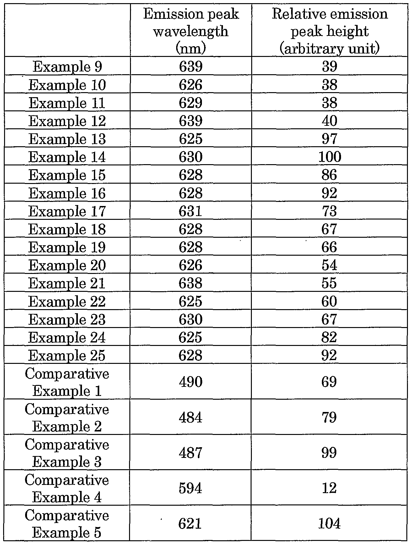


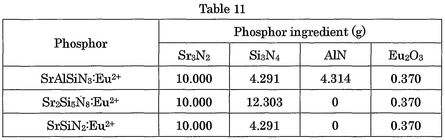

Claims
Priority Applications (18)
| Application Number | Priority Date | Filing Date | Title |
|---|---|---|---|
| KR1020077015970A KR101041311B1 (en) | 2004-04-27 | 2005-04-26 | Phosphor composition and method for producing the same, and light-emitting device using the same |
| KR1020087014853A KR100887489B1 (en) | 2004-04-27 | 2005-04-26 | Phosphor composition and method for producing the same, and light-emitting device using the same |
| US11/568,149 US7391060B2 (en) | 2004-04-27 | 2005-04-26 | Phosphor composition and method for producing the same, and light-emitting device using the same |
| KR1020087007101A KR100865624B1 (en) | 2004-04-27 | 2005-04-26 | Phosphor composition and method for producing the same, and light-emitting device using the same |
| KR1020087007102A KR100900372B1 (en) | 2004-04-27 | 2005-04-26 | Phosphor composition and method for producing the same, and light-emitting device using the same |
| EP05736612.2A EP1749074B1 (en) | 2004-04-27 | 2005-04-26 | Light-emitting device using phosphor composition |
| KR1020097010819A KR101157313B1 (en) | 2004-04-27 | 2005-04-26 | Phosphor composition and method for producing the same, and light-emitting device using the same |
| KR1020087007100A KR100847957B1 (en) | 2004-04-27 | 2005-04-26 | Phosphor composition and method for producing the same, and light-emitting device using the same |
| KR1020067024124A KR100777501B1 (en) | 2004-04-27 | 2005-04-26 | Phosphor composition and method for producing the same, and light-emitting device using the same |
| US11/891,386 US7507354B2 (en) | 2004-04-27 | 2007-08-10 | Phosphor composition and method for producing the same, and light-emitting device using the same |
| US12/099,555 US7615797B2 (en) | 2004-04-27 | 2008-04-08 | Phosphor composition and method for producing the same, and light-emitting device using the same |
| US12/099,584 US7651634B2 (en) | 2004-04-27 | 2008-04-08 | Phosphor composition and method for producing the same, and light-emitting device using the same |
| US12/099,511 US8221649B2 (en) | 2004-04-27 | 2008-04-08 | Phosphor composition and method for producing the same, and light-emitting device using the same |
| US12/141,616 US7811472B2 (en) | 2004-04-27 | 2008-06-18 | Phosphor composition and method for producing the same, and light-emitting device using the same |
| US12/485,627 US7892453B2 (en) | 2004-04-27 | 2009-06-16 | Phosphor composition and method for producing the same, and light-emitting device using the same |
| US12/535,442 US8226853B2 (en) | 2004-04-27 | 2009-08-04 | Phosphor composition and method for producing the same, and light-emitting device using the same |
| US13/473,195 US8419975B2 (en) | 2004-04-27 | 2012-05-16 | Phosphor composition and method for producing the same, and light-emitting device using the same |
| US13/845,976 US8551362B2 (en) | 2004-04-27 | 2013-03-18 | Phosphor composition and method for producing the same, and light-emitting device using the same |
Applications Claiming Priority (10)
| Application Number | Priority Date | Filing Date | Title |
|---|---|---|---|
| JP2004-131770 | 2004-04-27 | ||
| JP2004131770 | 2004-04-27 | ||
| JP2004-182797 | 2004-06-21 | ||
| JP2004182797 | 2004-06-21 | ||
| JP2004-194196 | 2004-06-30 | ||
| JP2004194196 | 2004-06-30 | ||
| JP2004-250739 | 2004-08-30 | ||
| JP2004250739A JP2005336450A (en) | 2004-04-27 | 2004-08-30 | Phosphor composition, method for producing the same and light-emitting device using the same phosphor composition |
| JP2004-363534 | 2004-12-15 | ||
| JP2004363534A JP4128564B2 (en) | 2004-04-27 | 2004-12-15 | Light emitting device |
Related Child Applications (2)
| Application Number | Title | Priority Date | Filing Date |
|---|---|---|---|
| US11/568,149 A-371-Of-International US7391060B2 (en) | 2004-04-27 | 2005-04-26 | Phosphor composition and method for producing the same, and light-emitting device using the same |
| US11/891,386 Continuation US7507354B2 (en) | 2004-04-27 | 2007-08-10 | Phosphor composition and method for producing the same, and light-emitting device using the same |
Publications (1)
| Publication Number | Publication Date |
|---|---|
| WO2005103199A1 true WO2005103199A1 (en) | 2005-11-03 |
Family
ID=34968845
Family Applications (1)
| Application Number | Title | Priority Date | Filing Date |
|---|---|---|---|
| PCT/JP2005/008395 WO2005103199A1 (en) | 2004-04-27 | 2005-04-26 | Phosphor composition and method for producing the same, and light-emitting device using the same |
Country Status (4)
| Country | Link |
|---|---|
| US (10) | US7391060B2 (en) |
| EP (3) | EP2113549B1 (en) |
| KR (7) | KR100865624B1 (en) |
| WO (1) | WO2005103199A1 (en) |
Cited By (54)
| Publication number | Priority date | Publication date | Assignee | Title |
|---|---|---|---|---|
| WO2007007236A3 (en) * | 2005-07-14 | 2007-03-29 | Philips Intellectual Property | Electroluminescent device |
| WO2007116850A1 (en) | 2006-03-27 | 2007-10-18 | Toyoda Gosei Co., Ltd. | Ferrous-metal-alkaline-earth-metal silicate mixed crystal phosphor and light emitting device using the same |
| WO2007120216A2 (en) * | 2005-11-22 | 2007-10-25 | Gelcore Llc | Charge compensated nitride phosphors for use in lighting applications |
| WO2008056713A1 (en) | 2006-11-07 | 2008-05-15 | Sony Corporation | Display device |
| EP1964906A1 (en) * | 2005-12-21 | 2008-09-03 | NEC Lighting, Ltd. | Yellow light-emitting phosphor and white light-emitting device using same |
| WO2008129454A2 (en) * | 2007-04-20 | 2008-10-30 | Philips Intellectual Property & Standards Gmbh | White emitting light source and luminescent material with improved colour stability |
| EP2009078A1 (en) * | 2007-06-29 | 2008-12-31 | Leuchtstoffwerk Breitungen GmbH | Ce3+, Eu2+ -activated alkaline earth silicon nitride phosphors |
| WO2009003988A1 (en) * | 2007-06-29 | 2009-01-08 | Leuchtstoffwerk Breitungen Gmbh | Ce3+, eu2+ and mn2+ - activated alkaline earth silicon nitride phosphors and white-light emitting led |
| EP2038938A1 (en) * | 2006-06-30 | 2009-03-25 | Seoul Semiconductor Co., Ltd. | Light emitting device |
| WO2009050611A1 (en) * | 2007-10-15 | 2009-04-23 | Philips Intellectual Property & Standards Gmbh | Light emitting device comprising a multiphase sialon-based ceramic material |
| EP2060615A1 (en) * | 2006-08-25 | 2009-05-20 | Sony Corporation | Luminescent composition, light source and display |
| EP1967565A3 (en) * | 2006-12-20 | 2009-11-04 | NEC Lighting, Ltd. | Red emitting nitride fluorescent material and white light emitting device using the same |
| US20100038665A1 (en) * | 2006-10-12 | 2010-02-18 | Panasonic Corporation | Light-emitting device and method for manufacturing the same |
| WO2010020495A1 (en) * | 2008-08-18 | 2010-02-25 | Osram Gesellschaft mit beschränkter Haftung | Alpha-sialon phosphor |
| EP2189509A1 (en) * | 2007-09-03 | 2010-05-26 | Showa Denko K.K. | Phosphor, method for producing the same, and light-emitting device using the same |
| WO2010057572A2 (en) * | 2008-11-22 | 2010-05-27 | Merck Patent Gmbh | Codoped 1-1-2 nitrides |
| US7807071B2 (en) * | 2006-08-03 | 2010-10-05 | Nichia Corporation | Light emitting apparatus |
| US7824573B2 (en) | 2005-04-01 | 2010-11-02 | Mitsubishi Chemical Corporation | Alloy powder for material of inorganic functional material precursor and phosphor |
| US7832312B2 (en) * | 2005-08-23 | 2010-11-16 | Samsung Led Co., Ltd. | Composite phosphor powder, light emitting device using the same and method for manufacturing composite phosphor powder |
| US7859182B2 (en) | 2005-08-31 | 2010-12-28 | Lumination Llc | Warm white LED-based lamp incoporating divalent EU-activated silicate yellow emitting phosphor |
| US7892453B2 (en) | 2004-04-27 | 2011-02-22 | Panasonic Corporation | Phosphor composition and method for producing the same, and light-emitting device using the same |
| US7938983B2 (en) | 2005-03-09 | 2011-05-10 | Koninklijke Philips Electronics N.V. | Illumination system comprising a radiation source and a fluorescent material |
| EP2345078A1 (en) * | 2008-10-24 | 2011-07-20 | Cree, Inc. | Lighting device using solid state light emitting devices having a transparent heat sink |
| CN102185059A (en) * | 2011-04-12 | 2011-09-14 | 天津理工大学 | Two-way voltage driven inorganic quantum dot electroluminescent device and preparation method thereof |
| US8040467B2 (en) | 2004-04-26 | 2011-10-18 | Mitsubishi Chemical Corporation | Blue color composition for color filter, color filter, and color image display device |
| WO2011147517A1 (en) * | 2010-05-22 | 2011-12-01 | Merck Patent Gmbh | Luminescent substances |
| US8137584B2 (en) * | 2006-10-30 | 2012-03-20 | Sony Corporation | Luminescent composition, light source device, display device and process for preparing luminescent composition |
| US20120068595A1 (en) * | 2007-07-09 | 2012-03-22 | Sharp Kabushiki Kaisha | Phosphor particle group and light emitting apparatus using the same |
| US8148887B2 (en) | 2004-02-18 | 2012-04-03 | National Institute For Materials Science | Light emitting diode lamp and light emitting device |
| US8153025B2 (en) * | 2007-02-06 | 2012-04-10 | Koninklijke Philips Electronics N.V. | Red emitting luminescent materials |
| US8206611B2 (en) | 2005-05-24 | 2012-06-26 | Mitsubishi Chemical Corporation | Phosphor and use thereof |
| CN101374926B (en) * | 2006-02-09 | 2012-08-29 | 宇部兴产株式会社 | Method for production of blue-light-emitting fluorescent material |
| US20120267997A1 (en) * | 2005-03-18 | 2012-10-25 | Mitsubishi Chemical Corporation | Light-emitting device, white light-emitting device, illuminator, and image display |
| EP2527418A1 (en) * | 2010-09-09 | 2012-11-28 | Jiangsu Bree Optronics Co. Ltd. | White-light led red luminescent materials and preparation methods thereof |
| JP2013007610A (en) * | 2011-06-23 | 2013-01-10 | Canon Inc | Color measuring unit and image forming apparatus |
| EP2551927A1 (en) * | 2011-07-29 | 2013-01-30 | LG Innotek Co., Ltd. | Light emitting device package |
| US8409470B2 (en) | 2003-11-26 | 2013-04-02 | Independent Administrative Institution National Institute For Materials Science | Phosphor and light-emitting equipment using phosphor |
| US8415870B2 (en) | 2008-08-28 | 2013-04-09 | Panasonic Corporation | Semiconductor light emitting device and backlight source, backlight source system, display device and electronic device using the same |
| US8451401B2 (en) | 2006-04-19 | 2013-05-28 | Mitsubishi Chemical Corporation | Color image display device |
| US8460579B2 (en) | 2007-04-17 | 2013-06-11 | Osram Gesellschaft mit beschränkter Haftung | Red-emitting luminophore and light source comprising such a luminophore |
| JP2013127855A (en) * | 2011-12-16 | 2013-06-27 | Panasonic Corp | Lighting device |
| CN103184049A (en) * | 2011-12-28 | 2013-07-03 | 湖南信多利新材料有限公司 | Preparation method for nitride fluorescent powder and equipment for same |
| US8546845B2 (en) | 2007-12-03 | 2013-10-01 | Koninklijke Philips N.V. | Light emitting device comprising a green emitting sialon-based material |
| US8550645B2 (en) | 2008-11-28 | 2013-10-08 | Showa Denko K.K. | Illumination device for display device, and display device |
| EP2692825A2 (en) * | 2011-03-29 | 2014-02-05 | Industry-Academy Cooperation Corps. Of Sunchon National University | Oxynitride-based phosphor |
| US8941566B2 (en) * | 2007-03-08 | 2015-01-27 | 3M Innovative Properties Company | Array of luminescent elements |
| EP2808374A4 (en) * | 2012-01-27 | 2015-05-06 | Denki Kagaku Kogyo Kk | Phosphor, method for producing same, and use of same |
| US9279079B2 (en) * | 2007-05-30 | 2016-03-08 | Sharp Kabushiki Kaisha | Method of manufacturing phosphor, light-emitting device, and image display apparatus |
| EP2546897A4 (en) * | 2010-03-12 | 2016-03-23 | Toshiba Kk | White light illumination device |
| US9617469B2 (en) | 2011-01-06 | 2017-04-11 | Shin-Etsu Chemical Co., Ltd. | Phosphor particles, making method, and light-emitting diode |
| US9624427B2 (en) | 2006-11-24 | 2017-04-18 | Ge Phosphors Technology, Llc | Phosphor, method of producing the same, and light emitting apparatus |
| US9944851B2 (en) | 2015-08-28 | 2018-04-17 | Nichia Corporation | Nitride fluorescent material, method for producing the same, and light emitting device |
| WO2018092696A1 (en) * | 2016-11-15 | 2018-05-24 | デンカ株式会社 | Red-emitting phosphor, light-emitting member, and light-emitting device |
| WO2019057426A1 (en) * | 2017-09-21 | 2019-03-28 | Heraeus Noblelight Gmbh | Broadband semiconductor-based uv light source for a spectral analysis device |
Families Citing this family (222)
| Publication number | Priority date | Publication date | Assignee | Title |
|---|---|---|---|---|
| DE10036940A1 (en) * | 2000-07-28 | 2002-02-07 | Patent Treuhand Ges Fuer Elektrische Gluehlampen Mbh | Luminescence conversion LED |
| US7915085B2 (en) | 2003-09-18 | 2011-03-29 | Cree, Inc. | Molded chip fabrication method |
| TWI359187B (en) * | 2003-11-19 | 2012-03-01 | Panasonic Corp | Method for preparing nitridosilicate-based compoun |
| JP4565141B2 (en) * | 2004-06-30 | 2010-10-20 | 独立行政法人物質・材料研究機構 | Phosphors and light emitting devices |
| JP4511885B2 (en) * | 2004-07-09 | 2010-07-28 | Dowaエレクトロニクス株式会社 | Phosphor, LED and light source |
| JP4422653B2 (en) * | 2004-07-28 | 2010-02-24 | Dowaエレクトロニクス株式会社 | Phosphor, production method thereof, and light source |
| US7476338B2 (en) * | 2004-08-27 | 2009-01-13 | Dowa Electronics Materials Co., Ltd. | Phosphor and manufacturing method for the same, and light source |
| DE112005001982T5 (en) * | 2004-08-31 | 2007-08-02 | Sumitomo Chemical Co., Ltd. | Fluorescent substance |
| US9070850B2 (en) | 2007-10-31 | 2015-06-30 | Cree, Inc. | Light emitting diode package and method for fabricating same |
| KR101142519B1 (en) * | 2005-03-31 | 2012-05-08 | 서울반도체 주식회사 | Backlight panel employing white light emitting diode having red phosphor and green phosphor |
| US8088302B2 (en) * | 2005-05-24 | 2012-01-03 | Seoul Semiconductor Co., Ltd. | Green phosphor of thiogallate, red phosphor of alkaline earth sulfide and white light emitting device thereof |
| JP2007049114A (en) | 2005-05-30 | 2007-02-22 | Sharp Corp | Light emitting device and method of manufacturing the same |
| US8215815B2 (en) | 2005-06-07 | 2012-07-10 | Oree, Inc. | Illumination apparatus and methods of forming the same |
| US8272758B2 (en) | 2005-06-07 | 2012-09-25 | Oree, Inc. | Illumination apparatus and methods of forming the same |
| US8128272B2 (en) | 2005-06-07 | 2012-03-06 | Oree, Inc. | Illumination apparatus |
| DE112006001722B4 (en) * | 2005-07-01 | 2021-05-06 | National Institute For Materials Science | Phosphor and process for its production and use of the phosphor |
| US20070052342A1 (en) * | 2005-09-01 | 2007-03-08 | Sharp Kabushiki Kaisha | Light-emitting device |
| KR100724591B1 (en) * | 2005-09-30 | 2007-06-04 | 서울반도체 주식회사 | Light emitting device and LCD backlight using the same |
| DE102006004397A1 (en) * | 2005-09-30 | 2007-04-05 | Osram Opto Semiconductors Gmbh | Optoelectronic component, e.g. light emitting diode, has housing with housing material that is permeable for useful radiation and has radiation absorbing particles to adjust predetermined radiation or luminous intensity of radiation |
| KR100764148B1 (en) * | 2006-01-17 | 2007-10-05 | 루시미아 주식회사 | Sheet type phosphors, preparation method thereof, and light emitting devices using these phosphors |
| WO2007091687A1 (en) * | 2006-02-10 | 2007-08-16 | Mitsubishi Chemical Corporation | Phosphor, method for producing same, phosphor-containing composition, light-emitting device, image display, and illuminating device |
| US8323529B2 (en) * | 2006-03-16 | 2012-12-04 | Seoul Semiconductor Co., Ltd. | Fluorescent material and light emitting diode using the same |
| JP2007300069A (en) * | 2006-04-04 | 2007-11-15 | Toyoda Gosei Co Ltd | Light emitting element, light emitting device using same, and method for manufacturing same |
| KR100731678B1 (en) * | 2006-05-08 | 2007-06-22 | 서울반도체 주식회사 | Chip-type led package and light emitting apparatus having the same |
| US8123980B2 (en) * | 2006-05-19 | 2012-02-28 | Mitsubishi Chemical Corporation | Nitrogen-containing alloy and method for producing phosphor using same |
| US7923928B2 (en) | 2006-06-27 | 2011-04-12 | Mitsubishi Chemical Corporation | Illuminating device |
| DE102006036577A1 (en) * | 2006-08-04 | 2008-02-07 | Patent-Treuhand-Gesellschaft für elektrische Glühlampen mbH | Red emitting phosphor and light source with such phosphor |
| US7915527B1 (en) | 2006-08-23 | 2011-03-29 | Rockwell Collins, Inc. | Hermetic seal and hermetic connector reinforcement and repair with low temperature glass coatings |
| US8174830B2 (en) | 2008-05-06 | 2012-05-08 | Rockwell Collins, Inc. | System and method for a substrate with internal pumped liquid metal for thermal spreading and cooling |
| US8581108B1 (en) | 2006-08-23 | 2013-11-12 | Rockwell Collins, Inc. | Method for providing near-hermetically coated integrated circuit assemblies |
| US8637980B1 (en) | 2007-12-18 | 2014-01-28 | Rockwell Collins, Inc. | Adhesive applications using alkali silicate glass for electronics |
| US8084855B2 (en) | 2006-08-23 | 2011-12-27 | Rockwell Collins, Inc. | Integrated circuit tampering protection and reverse engineering prevention coatings and methods |
| US8076185B1 (en) | 2006-08-23 | 2011-12-13 | Rockwell Collins, Inc. | Integrated circuit protection and ruggedization coatings and methods |
| US8166645B2 (en) * | 2006-08-23 | 2012-05-01 | Rockwell Collins, Inc. | Method for providing near-hermetically coated, thermally protected integrated circuit assemblies |
| US8617913B2 (en) | 2006-08-23 | 2013-12-31 | Rockwell Collins, Inc. | Alkali silicate glass based coating and method for applying |
| US8232564B2 (en) * | 2007-01-22 | 2012-07-31 | Cree, Inc. | Wafer level phosphor coating technique for warm light emitting diodes |
| US9159888B2 (en) | 2007-01-22 | 2015-10-13 | Cree, Inc. | Wafer level phosphor coating method and devices fabricated utilizing method |
| US9024349B2 (en) | 2007-01-22 | 2015-05-05 | Cree, Inc. | Wafer level phosphor coating method and devices fabricated utilizing method |
| US9711703B2 (en) | 2007-02-12 | 2017-07-18 | Cree Huizhou Opto Limited | Apparatus, system and method for use in mounting electronic elements |
| JP5476128B2 (en) * | 2007-02-22 | 2014-04-23 | クリー インコーポレイテッド | Illumination device, illumination method, optical filter, and light filtering method |
| DE102007015474A1 (en) * | 2007-03-30 | 2008-10-02 | Osram Opto Semiconductors Gmbh | Electromagnetic radiation-emitting optoelectronic component and method for producing an optoelectronic component |
| US7781779B2 (en) * | 2007-05-08 | 2010-08-24 | Luminus Devices, Inc. | Light emitting devices including wavelength converting material |
| EP2175007A4 (en) * | 2007-06-29 | 2011-10-19 | Mitsubishi Chem Corp | Phosphor, method for producing phosphor, phosphor-containing composition, and light-emitting device |
| WO2009011205A1 (en) * | 2007-07-19 | 2009-01-22 | Sharp Kabushiki Kaisha | Light emitting device |
| JP2009046668A (en) * | 2007-08-21 | 2009-03-05 | Samsung Sdi Co Ltd | White phosphor, light emitting device and display device using the same |
| JPWO2009028656A1 (en) * | 2007-08-30 | 2010-12-02 | 日亜化学工業株式会社 | Light emitting device |
| US8866169B2 (en) * | 2007-10-31 | 2014-10-21 | Cree, Inc. | LED package with increased feature sizes |
| US9041285B2 (en) | 2007-12-14 | 2015-05-26 | Cree, Inc. | Phosphor distribution in LED lamps using centrifugal force |
| US8363189B2 (en) * | 2007-12-18 | 2013-01-29 | Rockwell Collins, Inc. | Alkali silicate glass for displays |
| US8550684B2 (en) | 2007-12-19 | 2013-10-08 | Oree, Inc. | Waveguide-based packaging structures and methods for discrete lighting elements |
| US20090161369A1 (en) | 2007-12-19 | 2009-06-25 | Keren Regev | Waveguide sheet and methods for manufacturing the same |
| US8878219B2 (en) | 2008-01-11 | 2014-11-04 | Cree, Inc. | Flip-chip phosphor coating method and devices fabricated utilizing method |
| JP2009167338A (en) * | 2008-01-18 | 2009-07-30 | Sharp Corp | Wavelength conversion member, light emitting device having it, and phosphor |
| US8436526B2 (en) * | 2008-02-11 | 2013-05-07 | Sensor Electronic Technology, Inc. | Multiwavelength solid-state lamps with an enhanced number of rendered colors |
| WO2009110285A1 (en) | 2008-03-03 | 2009-09-11 | シャープ株式会社 | Light-emitting device |
| US8231237B2 (en) * | 2008-03-05 | 2012-07-31 | Oree, Inc. | Sub-assembly and methods for forming the same |
| US7990045B2 (en) * | 2008-03-15 | 2011-08-02 | Sensor Electronic Technology, Inc. | Solid-state lamps with partial conversion in phosphors for rendering an enhanced number of colors |
| JP2009227701A (en) * | 2008-03-19 | 2009-10-08 | Niigata Univ | Phosphor and method for producing it |
| JP2011515536A (en) * | 2008-03-21 | 2011-05-19 | ナノグラム・コーポレイション | Metallic silicon nitride or metallic silicon oxynitride submicron phosphor particles and method of synthesizing these particles |
| US8598618B2 (en) * | 2008-04-17 | 2013-12-03 | Kabushiki Kaisha Toshiba | White light emitting device, backlight, liquid crystal display device, and illuminating device |
| US8205337B2 (en) * | 2008-09-12 | 2012-06-26 | Rockwell Collins, Inc. | Fabrication process for a flexible, thin thermal spreader |
| US8650886B2 (en) * | 2008-09-12 | 2014-02-18 | Rockwell Collins, Inc. | Thermal spreader assembly with flexible liquid cooling loop having rigid tubing sections and flexible tubing sections |
| US8221089B2 (en) | 2008-09-12 | 2012-07-17 | Rockwell Collins, Inc. | Thin, solid-state mechanism for pumping electrically conductive liquids in a flexible thermal spreader |
| US8616266B2 (en) * | 2008-09-12 | 2013-12-31 | Rockwell Collins, Inc. | Mechanically compliant thermal spreader with an embedded cooling loop for containing and circulating electrically-conductive liquid |
| US8274215B2 (en) | 2008-12-15 | 2012-09-25 | Intematix Corporation | Nitride-based, red-emitting phosphors |
| US8242525B2 (en) * | 2008-05-20 | 2012-08-14 | Lightscape Materials, Inc. | Silicate-based phosphors and LED lighting devices using the same |
| TWI497747B (en) * | 2008-06-02 | 2015-08-21 | Panasonic Corp | Semiconductor light emitting apparatus and light source apparatus using the same |
| US8691113B2 (en) | 2008-07-02 | 2014-04-08 | Dexerials Corporation | Red phosphor, method for producing red phosphor, white light source, illuminating device, and liquid crystal display device |
| US8297786B2 (en) | 2008-07-10 | 2012-10-30 | Oree, Inc. | Slim waveguide coupling apparatus and method |
| US8301002B2 (en) | 2008-07-10 | 2012-10-30 | Oree, Inc. | Slim waveguide coupling apparatus and method |
| US8378369B2 (en) | 2008-09-09 | 2013-02-19 | Showa Denko K.K. | Light emitting unit, light emitting module, and display device |
| US8119040B2 (en) | 2008-09-29 | 2012-02-21 | Rockwell Collins, Inc. | Glass thick film embedded passive material |
| JP2010090231A (en) * | 2008-10-07 | 2010-04-22 | Canon Inc | Image display |
| US20100098377A1 (en) * | 2008-10-16 | 2010-04-22 | Noam Meir | Light confinement using diffusers |
| KR101601621B1 (en) * | 2008-11-14 | 2016-03-17 | 삼성전자주식회사 | Semiconductor Light Emitting Device |
| US9428688B2 (en) | 2008-11-17 | 2016-08-30 | Cree, Inc. | Phosphor composition |
| TWI391471B (en) * | 2008-11-21 | 2013-04-01 | Univ Nat Cheng Kung | Preparation method of nitride fluorescent powder |
| US8360617B2 (en) * | 2008-11-25 | 2013-01-29 | Samsung Electronics Co., Ltd. | Lighting system including LED with glass-coated quantum-dots |
| US8456082B2 (en) | 2008-12-01 | 2013-06-04 | Ifire Ip Corporation | Surface-emission light source with uniform illumination |
| US8368112B2 (en) | 2009-01-14 | 2013-02-05 | Cree Huizhou Opto Limited | Aligned multiple emitter package |
| US8624527B1 (en) | 2009-03-27 | 2014-01-07 | Oree, Inc. | Independently controllable illumination device |
| JP5710597B2 (en) * | 2009-04-28 | 2015-04-30 | キユーデイー・ビジヨン・インコーポレーテツド | Optical material, optical component and method |
| CN102316785B (en) * | 2009-05-12 | 2014-10-08 | 奥林巴斯医疗株式会社 | Subject in-vivo imaging system and subject in-vivo introducing device |
| US20100320904A1 (en) | 2009-05-13 | 2010-12-23 | Oree Inc. | LED-Based Replacement Lamps for Incandescent Fixtures |
| US8727597B2 (en) | 2009-06-24 | 2014-05-20 | Oree, Inc. | Illumination apparatus with high conversion efficiency and methods of forming the same |
| WO2011024818A1 (en) | 2009-08-26 | 2011-03-03 | 三菱化学株式会社 | Semiconductor white light-emitting device |
| WO2011024296A1 (en) | 2009-08-28 | 2011-03-03 | 株式会社 東芝 | Process for producing fluorescent substance and fluorescent substance produced thereby |
| US8933644B2 (en) | 2009-09-18 | 2015-01-13 | Soraa, Inc. | LED lamps with improved quality of light |
| CN102630349B (en) * | 2009-09-18 | 2017-06-13 | 天空公司 | Method power led and using current density operation |
| US9583678B2 (en) | 2009-09-18 | 2017-02-28 | Soraa, Inc. | High-performance LED fabrication |
| CN102471684B (en) * | 2009-09-18 | 2014-10-01 | 三井金属矿业株式会社 | Phosphor |
| US9293644B2 (en) | 2009-09-18 | 2016-03-22 | Soraa, Inc. | Power light emitting diode and method with uniform current density operation |
| WO2011060180A1 (en) | 2009-11-11 | 2011-05-19 | Qd Vision, Inc. | Device including quantum dots |
| US20110127905A1 (en) * | 2009-12-02 | 2011-06-02 | General Electric Company | Alkaline earth borate phosphors |
| US10147850B1 (en) * | 2010-02-03 | 2018-12-04 | Soraa, Inc. | System and method for providing color light sources in proximity to predetermined wavelength conversion structures |
| US8740413B1 (en) | 2010-02-03 | 2014-06-03 | Soraa, Inc. | System and method for providing color light sources in proximity to predetermined wavelength conversion structures |
| US8905588B2 (en) * | 2010-02-03 | 2014-12-09 | Sorra, Inc. | System and method for providing color light sources in proximity to predetermined wavelength conversion structures |
| WO2011105666A1 (en) * | 2010-02-24 | 2011-09-01 | Shim Hyun-Seop | Uv coating composition for led color conversion |
| WO2011108053A1 (en) * | 2010-03-01 | 2011-09-09 | パナソニック株式会社 | Led lamp and led illumination device |
| US8643038B2 (en) * | 2010-03-09 | 2014-02-04 | Cree, Inc. | Warm white LEDs having high color rendering index values and related luminophoric mediums |
| US8508127B2 (en) * | 2010-03-09 | 2013-08-13 | Cree, Inc. | High CRI lighting device with added long-wavelength blue color |
| US20110220920A1 (en) * | 2010-03-09 | 2011-09-15 | Brian Thomas Collins | Methods of forming warm white light emitting devices having high color rendering index values and related light emitting devices |
| WO2011115820A1 (en) * | 2010-03-19 | 2011-09-22 | Nitto Denko Corporation | Garnet-based phosphor ceramic sheets for light emitting device |
| MX2013005202A (en) * | 2010-03-30 | 2013-11-20 | Changchn Inst Of Applied Chemistry Chinese Academy Of Sciences | Method, system and device for location. |
| JP2012060097A (en) * | 2010-06-25 | 2012-03-22 | Mitsubishi Chemicals Corp | White semiconductor light-emitting device |
| US10546846B2 (en) | 2010-07-23 | 2020-01-28 | Cree, Inc. | Light transmission control for masking appearance of solid state light sources |
| KR20130098322A (en) * | 2010-08-04 | 2013-09-04 | 우베 고산 가부시키가이샤 | Silicon nitride powder for siliconitride phosphor, caalsin3 phosphor using same, sr2si5n8 phosphor using same, (sr, ca)alsin3 phosphor using same, la3si6n11 phosphor using same, and methods for producing the phosphors |
| CN102376860A (en) | 2010-08-05 | 2012-03-14 | 夏普株式会社 | Light emitting apparatus and method for manufacturing thereof |
| CN102375314B (en) * | 2010-08-09 | 2013-12-04 | 台达电子工业股份有限公司 | Illumination system and projector using the same |
| KR101243773B1 (en) * | 2010-08-17 | 2013-03-14 | 순천대학교 산학협력단 | Wavelength converting composition for light emitting device and sollar cell, light emitting device and sollar cell comprising the composition, preparing method for the composition |
| TWI393763B (en) * | 2010-10-15 | 2013-04-21 | Chi Mei Corp | A phosphor and a light emitting device |
| TWI393764B (en) * | 2010-10-15 | 2013-04-21 | Chi Mei Corp | A phosphor and a light emitting device |
| JP2012099282A (en) * | 2010-10-29 | 2012-05-24 | Sharp Corp | Lighting system and headlight for vehicle |
| US8329484B2 (en) * | 2010-11-02 | 2012-12-11 | Tsmc Solid State Lighting Ltd. | Phosphor with Ce3+/Ce3+, Li+ doped luminescent materials |
| KR101235179B1 (en) * | 2010-11-02 | 2013-02-20 | 주식회사 에클립스 | OXYNITRIDE-BASED PHOSPHORS COMPOSING OF SiON ELEMENT FOR WHITE LEDs, MANUFACTURING METHOD THEREOF AND LEDs USING THE SAME |
| CN102464979A (en) * | 2010-11-09 | 2012-05-23 | 奇美实业股份有限公司 | Fluorophor and light emitting device |
| KR101087032B1 (en) | 2010-11-12 | 2011-11-30 | 재단법인서울대학교산학협력재단 | Fabrication method for masn phosphor |
| US8343785B2 (en) * | 2010-11-30 | 2013-01-01 | Taiwan Semiconductor Manufacturing Company, Ltd. | Nitridosilicate phosphor tunable light-emitting diodes by using UV and blue chips |
| EP2646523B1 (en) * | 2010-12-01 | 2015-11-25 | Koninklijke Philips N.V. | Red emitting luminescent materials |
| KR101843760B1 (en) | 2010-12-01 | 2018-05-14 | 닛토 덴코 가부시키가이샤 | Emissive ceramic materials having a dopant concentration gradient and methods of making and using the same |
| TWI447207B (en) * | 2010-12-08 | 2014-08-01 | Univ Nat Chiao Tung | Phosphors and light emitting device using the same |
| JP5864851B2 (en) | 2010-12-09 | 2016-02-17 | シャープ株式会社 | Light emitting device |
| US9166126B2 (en) | 2011-01-31 | 2015-10-20 | Cree, Inc. | Conformally coated light emitting devices and methods for providing the same |
| FI122809B (en) * | 2011-02-15 | 2012-07-13 | Marimils Oy | Light source and light source band |
| WO2013101280A2 (en) | 2011-04-11 | 2013-07-04 | Cree, Inc. | Solid state lighting device including green shifted red component |
| US8716731B2 (en) * | 2011-04-11 | 2014-05-06 | Tsmc Solid State Lighting Ltd. | Tunable phosphor for luminescent |
| KR101781437B1 (en) | 2011-04-29 | 2017-09-25 | 삼성전자주식회사 | White light emitting device, display apparatus and illumination apparatus |
| TWI505524B (en) * | 2011-05-20 | 2015-10-21 | Au Optronics Corp | Organic electroluminescent light source |
| JP2012246462A (en) | 2011-05-31 | 2012-12-13 | Sharp Corp | Light-emitting device |
| US8814621B2 (en) | 2011-06-03 | 2014-08-26 | Cree, Inc. | Methods of determining and making red nitride compositions |
| US8906263B2 (en) * | 2011-06-03 | 2014-12-09 | Cree, Inc. | Red nitride phosphors |
| CN103608938B (en) * | 2011-06-03 | 2017-03-08 | 西铁城电子株式会社 | Semiconductor light-emitting apparatus, display material irradiate to irradiate to be irradiated with illuminator, vegetable with illuminator, meat and are irradiated with illuminator, typically used illuminator and semiconductor light emitting system with illuminator, fresh fish |
| US8747697B2 (en) * | 2011-06-07 | 2014-06-10 | Cree, Inc. | Gallium-substituted yttrium aluminum garnet phosphor and light emitting devices including the same |
| CN102842679A (en) * | 2011-06-21 | 2012-12-26 | 海洋王照明科技股份有限公司 | Organic electroluminescent device and preparation method thereof |
| DE102011078402A1 (en) * | 2011-06-30 | 2013-01-03 | Osram Ag | Conversion element and light-emitting diode with such a conversion element |
| US20130016528A1 (en) * | 2011-07-11 | 2013-01-17 | Kevin Joseph Hathaway | Enhanced color gamut led backlighting unit |
| US20130062561A1 (en) * | 2011-09-09 | 2013-03-14 | Epistar Corporation | Phosphor and method of preparing the same |
| DE202011106052U1 (en) | 2011-09-23 | 2011-11-09 | Osram Ag | Light source with phosphor and associated lighting unit. |
| JP5872828B2 (en) * | 2011-09-28 | 2016-03-01 | 株式会社小糸製作所 | Light emitting module and phosphor |
| EP4332434A2 (en) | 2011-10-24 | 2024-03-06 | Seoul Semiconductor Co., Ltd. | White light source and white light source system using white light source |
| US8591072B2 (en) | 2011-11-16 | 2013-11-26 | Oree, Inc. | Illumination apparatus confining light by total internal reflection and methods of forming the same |
| WO2013102222A1 (en) | 2011-12-30 | 2013-07-04 | Intematix Corporation | Nitride phosphors with interstitial cations for charge balance |
| US8663502B2 (en) | 2011-12-30 | 2014-03-04 | Intematix Corporation | Red-emitting nitride-based phosphors |
| US9318669B2 (en) | 2012-01-30 | 2016-04-19 | Cree, Inc. | Methods of determining and making red nitride compositions |
| EP2813559A4 (en) * | 2012-02-09 | 2015-11-11 | Denki Kagaku Kogyo Kk | Fluorophore and light emitting device |
| CN104508082A (en) | 2012-03-06 | 2015-04-08 | 日东电工株式会社 | Ceramic body for light emitting devices |
| CA2807615C (en) | 2012-03-08 | 2020-06-30 | Simplehuman, Llc | Vanity mirror |
| TWI547208B (en) * | 2012-03-19 | 2016-08-21 | 友達光電股份有限公司 | Organic electroluminescent apparatus |
| WO2013158930A1 (en) * | 2012-04-18 | 2013-10-24 | Nitto Denko Corporation | Phosphor ceramics and methods of making the same |
| US9441155B2 (en) * | 2012-06-06 | 2016-09-13 | Sharp Kabushiki Kaisha | Wavelength converting member, light-emitting device, illuminating device, vehicle headlight, and method for producing wavelength converting member |
| WO2014006501A1 (en) | 2012-07-03 | 2014-01-09 | Yosi Shani | Planar remote phosphor illumination apparatus |
| US8597545B1 (en) | 2012-07-18 | 2013-12-03 | Intematix Corporation | Red-emitting nitride-based calcium-stabilized phosphors |
| KR20150035742A (en) * | 2012-07-20 | 2015-04-07 | 미쓰비시 가가꾸 가부시키가이샤 | Light emitting device, wavelength conversion member, phosphor composition, and phosphor mixture |
| DE102012106940A1 (en) * | 2012-07-30 | 2014-01-30 | Osram Gmbh | Manufacturing phosphor, comprises mixing starting materials comprising mixture of cationic component containing strontium, silicon, aluminum, europium and anionic component containing nitrogen and oxygen, and heating at reduced atmosphere |
| KR101476000B1 (en) * | 2012-08-03 | 2014-12-24 | 에스앤비인더스트리 주식회사 | The manufacturing method of led lamp for plant growth-promoting |
| US9435915B1 (en) | 2012-09-28 | 2016-09-06 | Rockwell Collins, Inc. | Antiglare treatment for glass |
| JP6068914B2 (en) | 2012-10-09 | 2017-01-25 | デンカ株式会社 | Method for manufacturing phosphor |
| US20140167601A1 (en) * | 2012-12-19 | 2014-06-19 | Cree, Inc. | Enhanced Luminous Flux Semiconductor Light Emitting Devices Including Red Phosphors that Exhibit Good Color Rendering Properties and Related Red Phosphors |
| US9761763B2 (en) | 2012-12-21 | 2017-09-12 | Soraa, Inc. | Dense-luminescent-materials-coated violet LEDs |
| CN102994079A (en) * | 2012-12-21 | 2013-03-27 | 北京有色金属研究总院 | Nitrogen-oxide orange-red fluorescent material comprising light-emitting film or light-emitting piece and light-emitting device |
| US9219202B2 (en) | 2013-04-19 | 2015-12-22 | Cree, Inc. | Semiconductor light emitting devices including red phosphors that exhibit good color rendering properties and related red phosphors |
| KR102075989B1 (en) | 2013-06-20 | 2020-02-11 | 삼성전자주식회사 | Red phosphor, light emitting device, display apparatus and illumination apparatus |
| JP6195760B2 (en) * | 2013-08-16 | 2017-09-13 | シチズン電子株式会社 | LED light emitting device |
| JP2015041633A (en) * | 2013-08-20 | 2015-03-02 | 船井電機株式会社 | Lighting device for food and lighting device for meat |
| USD737060S1 (en) | 2013-08-22 | 2015-08-25 | Simplehuman, Llc | Vanity mirror |
| US9410664B2 (en) | 2013-08-29 | 2016-08-09 | Soraa, Inc. | Circadian friendly LED light source |
| US10074781B2 (en) | 2013-08-29 | 2018-09-11 | Cree, Inc. | Semiconductor light emitting devices including multiple red phosphors that exhibit good color rendering properties with increased brightness |
| US9240528B2 (en) | 2013-10-03 | 2016-01-19 | Cree, Inc. | Solid state lighting apparatus with high scotopic/photopic (S/P) ratio |
| US9356201B2 (en) * | 2013-10-04 | 2016-05-31 | Bridgelux, Inc. | Die emitting white light |
| JP2015082596A (en) | 2013-10-23 | 2015-04-27 | 株式会社東芝 | Light-emitting device |
| USD736001S1 (en) | 2014-01-27 | 2015-08-11 | Simplehuman, Llc | Vanity mirror |
| USD751829S1 (en) | 2014-03-13 | 2016-03-22 | Simplehuman, Llc | Vanity mirror |
| KR102213650B1 (en) * | 2014-04-18 | 2021-02-08 | 대주전자재료 주식회사 | Acidic nitride-based fluorescent material and white light emitting apparatus using same |
| WO2015184614A1 (en) * | 2014-06-05 | 2015-12-10 | 上海富迪照明电器有限公司 | High-power high-temperature white light led package and manufacturing method thereof |
| US9601670B2 (en) | 2014-07-11 | 2017-03-21 | Cree, Inc. | Method to form primary optic with variable shapes and/or geometries without a substrate |
| WO2016021705A1 (en) | 2014-08-07 | 2016-02-11 | 三菱化学株式会社 | Phosphor, light-emitting device, image display device, and illumination device |
| TWI645579B (en) * | 2014-08-11 | 2018-12-21 | 佰鴻工業股份有限公司 | Light-emitting diode module with reduced blue light energy |
| US9200198B1 (en) | 2014-08-28 | 2015-12-01 | Lightscape Materials, Inc. | Inorganic phosphor and light emitting devices comprising same |
| US9315725B2 (en) | 2014-08-28 | 2016-04-19 | Lightscape Materials, Inc. | Method of making EU2+ activated inorganic red phosphor |
| US9200199B1 (en) | 2014-08-28 | 2015-12-01 | Lightscape Materials, Inc. | Inorganic red phosphor and lighting devices comprising same |
| US10622522B2 (en) | 2014-09-05 | 2020-04-14 | Theodore Lowes | LED packages with chips having insulated surfaces |
| CN106795429B (en) * | 2014-10-23 | 2020-06-12 | 三菱化学株式会社 | Phosphor, light emitting device, illumination device, and image display device |
| US20160149096A1 (en) * | 2014-11-24 | 2016-05-26 | Ledst Co., Ltd. | Prox reaction apparatus for fuel cell |
| US10076176B2 (en) | 2015-03-06 | 2018-09-18 | Simplehuman, Llc | Vanity mirror comprising light sources and methods of manufacture thereof |
| USD785345S1 (en) | 2015-03-06 | 2017-05-02 | Simplehuman, Llc | Mirror |
| CN104698530A (en) * | 2015-04-07 | 2015-06-10 | 京东方科技集团股份有限公司 | Light guide plate, front-arranged light source module, display module and display device |
| JP6202154B2 (en) * | 2015-08-28 | 2017-09-27 | 日亜化学工業株式会社 | Nitride phosphor, method of manufacturing the same, and light emitting device |
| JP6384468B2 (en) * | 2015-12-22 | 2018-09-05 | 日亜化学工業株式会社 | Light emitting device |
| US9882107B2 (en) * | 2016-01-12 | 2018-01-30 | Citizen Electronics Co., Ltd. | LED package with covered bonding wire |
| WO2017133459A1 (en) * | 2016-02-03 | 2017-08-10 | 欧普照明股份有限公司 | Light source module and illumination device |
| US10256374B2 (en) | 2016-03-04 | 2019-04-09 | Nichia Corporation | Light emitting device |
| JP6447557B2 (en) | 2016-03-24 | 2019-01-09 | 日亜化学工業株式会社 | Method for manufacturing light emitting device |
| JP6913538B2 (en) * | 2016-06-30 | 2021-08-04 | 花王株式会社 | Skin cosmetics |
| JP6418208B2 (en) * | 2016-08-24 | 2018-11-07 | 日亜化学工業株式会社 | Nitride phosphor and light emitting device |
| CN106322148B (en) * | 2016-10-21 | 2023-06-06 | 四川省桑瑞光辉标识系统股份有限公司 | Dimming system and method for LED lamp panel |
| US10290779B2 (en) * | 2016-12-15 | 2019-05-14 | Panasonic Intellectual Property Management Co., Ltd. | Light emitting element |
| KR102316099B1 (en) * | 2017-03-03 | 2021-10-25 | 엘지전자 주식회사 | Display device |
| USD816350S1 (en) | 2017-03-17 | 2018-05-01 | Simplehuman, Llc | Vanity mirror |
| US10869537B2 (en) | 2017-03-17 | 2020-12-22 | Simplehuman, Llc | Vanity mirror |
| US10340426B2 (en) * | 2017-07-06 | 2019-07-02 | Epistar Corporation | Phosphor and illumination device utilizing the same |
| TWI702362B (en) * | 2017-07-13 | 2020-08-21 | 東貝光電科技股份有限公司 | Led lighting device |
| CN111201304A (en) * | 2017-10-10 | 2020-05-26 | 电化株式会社 | Red phosphor and light-emitting device |
| US11387390B2 (en) | 2017-11-27 | 2022-07-12 | Nichia Corporation | Method for producing wavelength converting member, and wavelength converting member |
| JP6923804B2 (en) * | 2017-12-08 | 2021-08-25 | 日亜化学工業株式会社 | Wavelength conversion member and its manufacturing method |
| US10763414B2 (en) * | 2017-12-18 | 2020-09-01 | Rohm Co., Ltd. | Semiconductor light-emitting device |
| USD848158S1 (en) | 2017-12-28 | 2019-05-14 | Simplehuman, Llc | Vanity mirror |
| CA3033689A1 (en) | 2018-02-14 | 2019-08-14 | Simplehuman, Llc | Compact mirror |
| KR20190101787A (en) * | 2018-02-23 | 2019-09-02 | 서울반도체 주식회사 | Led lighting apparatus having improved color lendering and led filament |
| USD846288S1 (en) | 2018-03-08 | 2019-04-23 | Simplehuman, Llc | Vanity mirror |
| CA3037704A1 (en) | 2018-03-22 | 2019-09-22 | Simplehuman, Llc | Voice-activated vanity mirror |
| CN110342939A (en) | 2018-04-06 | 2019-10-18 | 日亚化学工业株式会社 | Manufacturing method, ceramic composite and the light emitting device of ceramic composite |
| USD874161S1 (en) | 2018-09-07 | 2020-02-04 | Simplehuman, Llc | Vanity mirror |
| US10935231B2 (en) | 2018-10-15 | 2021-03-02 | Aylo Llc | Systems and methods for a mirror mounted light with mobile device mounting |
| USD950118S1 (en) | 2018-10-15 | 2022-04-26 | Aylo, Llc | Light |
| USD925928S1 (en) | 2019-03-01 | 2021-07-27 | Simplehuman, Llc | Vanity mirror |
| WO2020180627A1 (en) | 2019-03-01 | 2020-09-10 | Simplehuman, Llc | Vanity mirror |
| WO2020186002A1 (en) * | 2019-03-13 | 2020-09-17 | Current Lighting Solutions, Llc | Horticulture lighting devices |
| EP3950884B1 (en) * | 2019-04-03 | 2022-08-24 | National Institute for Materials Science | Phosphor, method for producing same and light emitting element |
| USD927863S1 (en) | 2019-05-02 | 2021-08-17 | Simplehuman, Llc | Vanity mirror cover |
| USD899226S1 (en) | 2019-09-09 | 2020-10-20 | Aylo Llc | Suction cup mount |
| CN110635013A (en) * | 2019-09-20 | 2019-12-31 | 深圳市长方集团股份有限公司 | Full-spectrum cold-white LED light source excited by purple light |
| JP7332881B2 (en) * | 2019-09-30 | 2023-08-24 | 日亜化学工業株式会社 | light emitting device |
Citations (1)
| Publication number | Priority date | Publication date | Assignee | Title |
|---|---|---|---|---|
| WO2003080764A1 (en) * | 2002-03-22 | 2003-10-02 | Nichia Corporation | Nitride phosphor and method for preparation thereof, and light emitting device |
Family Cites Families (47)
| Publication number | Priority date | Publication date | Assignee | Title |
|---|---|---|---|---|
| TW383508B (en) * | 1996-07-29 | 2000-03-01 | Nichia Kagaku Kogyo Kk | Light emitting device and display |
| KR19980046311A (en) | 1996-12-12 | 1998-09-15 | 손욱 | Fluorescent projector |
| WO2000019546A1 (en) | 1998-09-28 | 2000-04-06 | Koninklijke Philips Electronics N.V. | Lighting system |
| US6429583B1 (en) * | 1998-11-30 | 2002-08-06 | General Electric Company | Light emitting device with ba2mgsi2o7:eu2+, ba2sio4:eu2+, or (srxcay ba1-x-y)(a1zga1-z)2sr:eu2+phosphors |
| EP1104799A1 (en) | 1999-11-30 | 2001-06-06 | Patent-Treuhand-Gesellschaft für elektrische Glühlampen mbH | Red emitting luminescent material |
| AU2001261130A1 (en) * | 2000-05-04 | 2001-11-12 | Kimberly-Clark Worldwide, Inc. | Salt-sensitive water-dispersible polymer composition |
| DE10026435A1 (en) * | 2000-05-29 | 2002-04-18 | Osram Opto Semiconductors Gmbh | Calcium-magnesium-chlorosilicate phosphor and its application in luminescence conversion LEDs |
| CN1203557C (en) | 2000-05-29 | 2005-05-25 | 电灯专利信托有限公司 | LED-based white-light emitting lighting unit |
| DE10036940A1 (en) | 2000-07-28 | 2002-02-07 | Patent Treuhand Ges Fuer Elektrische Gluehlampen Mbh | Luminescence conversion LED |
| US6850002B2 (en) * | 2000-07-28 | 2005-02-01 | Osram Opto Semiconductors Gmbh | Light emitting device for generating specific colored light, including white light |
| JP4619509B2 (en) | 2000-09-28 | 2011-01-26 | 株式会社東芝 | Light emitting device |
| US6524542B2 (en) * | 2001-04-12 | 2003-02-25 | Millennium Cell, Inc. | Processes for synthesizing borohydride compounds |
| AT410266B (en) * | 2000-12-28 | 2003-03-25 | Tridonic Optoelectronics Gmbh | LIGHT SOURCE WITH A LIGHT-EMITTING ELEMENT |
| DE10105800B4 (en) * | 2001-02-07 | 2017-08-31 | Osram Gmbh | Highly efficient phosphor and its use |
| US6632379B2 (en) * | 2001-06-07 | 2003-10-14 | National Institute For Materials Science | Oxynitride phosphor activated by a rare earth element, and sialon type phosphor |
| DE10133352A1 (en) * | 2001-07-16 | 2003-02-06 | Patent Treuhand Ges Fuer Elektrische Gluehlampen Mbh | Lighting unit with at least one LED as a light source |
| EP2017901A1 (en) * | 2001-09-03 | 2009-01-21 | Panasonic Corporation | Semiconductor light emitting device, light emitting apparatus and production method for semiconductor light emitting DEV |
| DE10146719A1 (en) | 2001-09-20 | 2003-04-17 | Patent Treuhand Ges Fuer Elektrische Gluehlampen Mbh | Lighting unit with at least one LED as a light source |
| DE10147040A1 (en) * | 2001-09-25 | 2003-04-24 | Patent Treuhand Ges Fuer Elektrische Gluehlampen Mbh | Lighting unit with at least one LED as a light source |
| JP3993854B2 (en) * | 2001-10-01 | 2007-10-17 | 松下電器産業株式会社 | Semiconductor light emitting element and light emitting device using the same |
| JP3985486B2 (en) | 2001-10-01 | 2007-10-03 | 松下電器産業株式会社 | Semiconductor light emitting element and light emitting device using the same |
| JP2003321675A (en) | 2002-04-26 | 2003-11-14 | Nichia Chem Ind Ltd | Nitride fluorophor and method for producing the same |
| JP4009828B2 (en) * | 2002-03-22 | 2007-11-21 | 日亜化学工業株式会社 | Nitride phosphor and method of manufacturing the same |
| AU2003215785A1 (en) * | 2002-03-25 | 2003-10-08 | Philips Intellectual Property And Standards Gmbh | Tri-color white light led lamp |
| US6809471B2 (en) | 2002-06-28 | 2004-10-26 | General Electric Company | Phosphors containing oxides of alkaline-earth and Group-IIIB metals and light sources incorporating the same |
| JP4407204B2 (en) | 2002-08-30 | 2010-02-03 | 日亜化学工業株式会社 | Light emitting device |
| EP1413619A1 (en) | 2002-09-24 | 2004-04-28 | Osram Opto Semiconductors GmbH | Luminescent material, especially for LED application |
| EP1413618A1 (en) * | 2002-09-24 | 2004-04-28 | Osram Opto Semiconductors GmbH | Luminescent material, especially for LED application |
| US6717353B1 (en) | 2002-10-14 | 2004-04-06 | Lumileds Lighting U.S., Llc | Phosphor converted light emitting device |
| MY149573A (en) | 2002-10-16 | 2013-09-13 | Nichia Corp | Oxynitride phosphor and production process thereof, and light-emitting device using oxynitride phosphor |
| JP4442101B2 (en) | 2003-03-14 | 2010-03-31 | 日亜化学工業株式会社 | Oxynitride phosphor and light emitting device using the same |
| JP2007504644A (en) | 2003-08-29 | 2007-03-01 | コーニンクレッカ フィリップス エレクトロニクス エヌ ヴィ | Color mixing lighting system |
| JP3837588B2 (en) * | 2003-11-26 | 2006-10-25 | 独立行政法人物質・材料研究機構 | Phosphors and light emitting devices using phosphors |
| JP3931239B2 (en) | 2004-02-18 | 2007-06-13 | 独立行政法人物質・材料研究機構 | Light emitting device and lighting apparatus |
| US7250715B2 (en) | 2004-02-23 | 2007-07-31 | Philips Lumileds Lighting Company, Llc | Wavelength converted semiconductor light emitting devices |
| JP4511849B2 (en) * | 2004-02-27 | 2010-07-28 | Dowaエレクトロニクス株式会社 | Phosphor and its manufacturing method, light source, and LED |
| JP3921545B2 (en) | 2004-03-12 | 2007-05-30 | 独立行政法人物質・材料研究機構 | Phosphor and production method thereof |
| KR100865624B1 (en) | 2004-04-27 | 2008-10-27 | 파나소닉 주식회사 | Phosphor composition and method for producing the same, and light-emitting device using the same |
| JP4128564B2 (en) * | 2004-04-27 | 2008-07-30 | 松下電器産業株式会社 | Light emitting device |
| JP4565141B2 (en) | 2004-06-30 | 2010-10-20 | 独立行政法人物質・材料研究機構 | Phosphors and light emitting devices |
| JP5226929B2 (en) | 2004-06-30 | 2013-07-03 | 三菱化学株式会社 | LIGHT EMITTING ELEMENT, LIGHTING DEVICE USING SAME, AND IMAGE DISPLAY DEVICE |
| US7138756B2 (en) * | 2004-08-02 | 2006-11-21 | Dowa Mining Co., Ltd. | Phosphor for electron beam excitation and color display device using the same |
| JP4543250B2 (en) * | 2004-08-27 | 2010-09-15 | Dowaエレクトロニクス株式会社 | Phosphor mixture and light emitting device |
| JP4543253B2 (en) * | 2004-10-28 | 2010-09-15 | Dowaエレクトロニクス株式会社 | Phosphor mixture and light emitting device |
| US7671529B2 (en) | 2004-12-10 | 2010-03-02 | Philips Lumileds Lighting Company, Llc | Phosphor converted light emitting device |
| CN101460880B (en) * | 2006-05-05 | 2012-05-23 | Prysm公司 | Phosphor compositions and other fluorescent materials for display systems and devices |
| JP4285580B1 (en) | 2008-02-22 | 2009-06-24 | 三菱自動車工業株式会社 | Shifting device for automatic transmission |
-
2005
- 2005-04-26 KR KR1020087007101A patent/KR100865624B1/en active IP Right Grant
- 2005-04-26 KR KR1020087007102A patent/KR100900372B1/en active IP Right Grant
- 2005-04-26 WO PCT/JP2005/008395 patent/WO2005103199A1/en active Application Filing
- 2005-04-26 EP EP09007211A patent/EP2113549B1/en active Active
- 2005-04-26 KR KR1020087014853A patent/KR100887489B1/en active IP Right Grant
- 2005-04-26 KR KR1020077015970A patent/KR101041311B1/en active IP Right Grant
- 2005-04-26 EP EP08010928A patent/EP1980605B1/en active Active
- 2005-04-26 EP EP05736612.2A patent/EP1749074B1/en active Active
- 2005-04-26 KR KR1020087007100A patent/KR100847957B1/en active IP Right Grant
- 2005-04-26 KR KR1020097010819A patent/KR101157313B1/en active IP Right Grant
- 2005-04-26 KR KR1020067024124A patent/KR100777501B1/en active IP Right Grant
- 2005-04-26 US US11/568,149 patent/US7391060B2/en active Active
-
2007
- 2007-08-10 US US11/891,386 patent/US7507354B2/en active Active
-
2008
- 2008-04-08 US US12/099,511 patent/US8221649B2/en active Active
- 2008-04-08 US US12/099,584 patent/US7651634B2/en active Active
- 2008-04-08 US US12/099,555 patent/US7615797B2/en active Active
- 2008-06-18 US US12/141,616 patent/US7811472B2/en active Active
-
2009
- 2009-06-16 US US12/485,627 patent/US7892453B2/en active Active
- 2009-08-04 US US12/535,442 patent/US8226853B2/en active Active
-
2012
- 2012-05-16 US US13/473,195 patent/US8419975B2/en active Active
-
2013
- 2013-03-18 US US13/845,976 patent/US8551362B2/en active Active
Patent Citations (1)
| Publication number | Priority date | Publication date | Assignee | Title |
|---|---|---|---|---|
| WO2003080764A1 (en) * | 2002-03-22 | 2003-10-02 | Nichia Corporation | Nitride phosphor and method for preparation thereof, and light emitting device |
Non-Patent Citations (5)
| Title |
|---|
| DATABASE WPI Section Ch Week 200372, Derwent World Patents Index; Class L03, AN 2003-767884, XP002344466 * |
| FANG CM, METSELAAR R: "First-principles calculations of the stability and local structure of ?-sialon ceramics on the line Si3N4?Ca3N2:3AlN", J. PHYS.: CONDENS. MATTER, vol. 16, no. 16, 28 April 2004 (2004-04-28), pages 2931 - 2939, XP002344462 * |
| XIE R-J ET AL: "EU2+-DOPED CA-ALPHA-SIALON: A YELLOW PHOSPHOR FOR WHITE LIGHT-EMITTING DIODES", APPLIED PHYSICS LETTERS, AMERICAN INSTITUTE OF PHYSICS. NEW YORK, US, vol. 84, no. 26, 28 June 2004 (2004-06-28), pages 5404 - 5406, XP001223479, ISSN: 0003-6951 * |
| XIE R-J ET AL: "Photoluminescence of Cerium-Doped -SiAlON Materials", J. AM. CERAM. SOC., vol. 87, no. 7, July 2004 (2004-07-01), pages 1368 - 1370, XP002344461 * |
| XIE R-J ET AL: "PREPARATION OF CA-ALPHA-SIALON CERAMICS WITH COMPOSITIONS ALONG THE SI3N4-1/2CA3N2:3AIN LINE", ZEITSCHRIFT FUR METALLKUNDE, HANSER, MUNCHEN, DE, vol. 92, no. 8, August 2001 (2001-08-01), pages 931 - 936, XP001075281, ISSN: 0044-3093 * |
Cited By (122)
| Publication number | Priority date | Publication date | Assignee | Title |
|---|---|---|---|---|
| US11084980B2 (en) | 2003-11-26 | 2021-08-10 | Mitsubishi Chemical Corporation | Phosphor and light-emitting equipment using phosphor |
| US11697765B2 (en) | 2003-11-26 | 2023-07-11 | Mitsubishi Chemical Corporation | Phosphor and light-emitting equipment using phosphor |
| US9738829B2 (en) | 2003-11-26 | 2017-08-22 | Mitsubishi Chemical Corporation | Phosphor and light-emitting equipment using phosphor |
| US10072207B2 (en) | 2003-11-26 | 2018-09-11 | Mitsubishi Chemical Corporation | Phosphor and light-emitting equipment using phosphor |
| US8409470B2 (en) | 2003-11-26 | 2013-04-02 | Independent Administrative Institution National Institute For Materials Science | Phosphor and light-emitting equipment using phosphor |
| US8148887B2 (en) | 2004-02-18 | 2012-04-03 | National Institute For Materials Science | Light emitting diode lamp and light emitting device |
| US8040467B2 (en) | 2004-04-26 | 2011-10-18 | Mitsubishi Chemical Corporation | Blue color composition for color filter, color filter, and color image display device |
| US8551362B2 (en) | 2004-04-27 | 2013-10-08 | Panasonic Corporation | Phosphor composition and method for producing the same, and light-emitting device using the same |
| US7892453B2 (en) | 2004-04-27 | 2011-02-22 | Panasonic Corporation | Phosphor composition and method for producing the same, and light-emitting device using the same |
| US8221649B2 (en) | 2004-04-27 | 2012-07-17 | Panasonic Corporation | Phosphor composition and method for producing the same, and light-emitting device using the same |
| US8226853B2 (en) | 2004-04-27 | 2012-07-24 | Panasonic Corporation | Phosphor composition and method for producing the same, and light-emitting device using the same |
| US8419975B2 (en) | 2004-04-27 | 2013-04-16 | Panasonic Corporation | Phosphor composition and method for producing the same, and light-emitting device using the same |
| CN101171884B (en) * | 2005-03-09 | 2015-09-23 | 飞利浦拉米尔德斯照明设备有限责任公司 | Comprise the illuminator of emission source and fluorescent material |
| US8038905B2 (en) | 2005-03-09 | 2011-10-18 | Koninklijke Philips Electronics N.V. | Illumination system comprising a radiation source and a fluorescent material |
| US7938983B2 (en) | 2005-03-09 | 2011-05-10 | Koninklijke Philips Electronics N.V. | Illumination system comprising a radiation source and a fluorescent material |
| US9028718B2 (en) * | 2005-03-18 | 2015-05-12 | Mitsubishi Chemical Corporation | Light-emitting device, white light-emitting device, illuminator, and image display |
| US20120267997A1 (en) * | 2005-03-18 | 2012-10-25 | Mitsubishi Chemical Corporation | Light-emitting device, white light-emitting device, illuminator, and image display |
| US8460580B2 (en) | 2005-04-01 | 2013-06-11 | Mitsubishi Chemical Corporation | Alloy powder for raw material of inorganic functional material and phosphor |
| US7824573B2 (en) | 2005-04-01 | 2010-11-02 | Mitsubishi Chemical Corporation | Alloy powder for material of inorganic functional material precursor and phosphor |
| US8801970B2 (en) | 2005-04-01 | 2014-08-12 | Mitsubishi Chemical Corporation | Europium- and strontium-based phosphor |
| US8703019B2 (en) | 2005-05-24 | 2014-04-22 | Mitsubishi Chemical Corporation | Phosphor and use thereof |
| US8206611B2 (en) | 2005-05-24 | 2012-06-26 | Mitsubishi Chemical Corporation | Phosphor and use thereof |
| US7952270B2 (en) | 2005-07-14 | 2011-05-31 | Koninklijke Philips Electronics N.V. | Electroluminescent device |
| WO2007007236A3 (en) * | 2005-07-14 | 2007-03-29 | Philips Intellectual Property | Electroluminescent device |
| US8012792B2 (en) | 2005-08-23 | 2011-09-06 | Samsung Led Co., Ltd. | Composite phosphor powder, light emitting device using the same and method for manufacturing composite phoshpor powder |
| US7832312B2 (en) * | 2005-08-23 | 2010-11-16 | Samsung Led Co., Ltd. | Composite phosphor powder, light emitting device using the same and method for manufacturing composite phosphor powder |
| US7859182B2 (en) | 2005-08-31 | 2010-12-28 | Lumination Llc | Warm white LED-based lamp incoporating divalent EU-activated silicate yellow emitting phosphor |
| WO2007120216A2 (en) * | 2005-11-22 | 2007-10-25 | Gelcore Llc | Charge compensated nitride phosphors for use in lighting applications |
| WO2007120216A3 (en) * | 2005-11-22 | 2007-12-21 | Gelcore Llc | Charge compensated nitride phosphors for use in lighting applications |
| DE112006003161B4 (en) * | 2005-11-22 | 2017-11-16 | Gelcore Llc | Charge-compensated nitride phosphors and their use |
| JP2009516774A (en) * | 2005-11-22 | 2009-04-23 | ルミネイション リミテッド ライアビリティ カンパニー | Charge compensated nitride phosphors for use in lighting applications |
| EP1964906A1 (en) * | 2005-12-21 | 2008-09-03 | NEC Lighting, Ltd. | Yellow light-emitting phosphor and white light-emitting device using same |
| EP1964906A4 (en) * | 2005-12-21 | 2010-04-21 | Nec Lighting Ltd | Yellow light-emitting phosphor and white light-emitting device using same |
| CN101374926B (en) * | 2006-02-09 | 2012-08-29 | 宇部兴产株式会社 | Method for production of blue-light-emitting fluorescent material |
| TWI414584B (en) * | 2006-02-09 | 2013-11-11 | Ube Industries | Process for producing a blue light emitting fluorescent material |
| US20100230691A1 (en) * | 2006-03-27 | 2010-09-16 | Mitsuhiro Inoue | Ferrous-Metal-Alkaline-Earth-Metal Silicate Mixed Crystal Phosphor and Light Emitting Device using The Same |
| KR101118336B1 (en) | 2006-03-27 | 2012-03-09 | 메르크 파텐트 게엠베하 | Ferrous-metal-alkaline-earth-metal silicate mixed crystal phosphor and light emitting device using the same |
| WO2007116850A1 (en) | 2006-03-27 | 2007-10-18 | Toyoda Gosei Co., Ltd. | Ferrous-metal-alkaline-earth-metal silicate mixed crystal phosphor and light emitting device using the same |
| US8451401B2 (en) | 2006-04-19 | 2013-05-28 | Mitsubishi Chemical Corporation | Color image display device |
| EP2038938A1 (en) * | 2006-06-30 | 2009-03-25 | Seoul Semiconductor Co., Ltd. | Light emitting device |
| US8053798B2 (en) | 2006-06-30 | 2011-11-08 | Seoul Semiconductor Co., Ltd. | Light emitting device |
| EP2038938A4 (en) * | 2006-06-30 | 2011-02-23 | Seoul Semiconductor Co Ltd | Light emitting device |
| CN101438428B (en) * | 2006-06-30 | 2012-01-25 | 首尔半导体株式会社 | Light emitting device |
| US7807071B2 (en) * | 2006-08-03 | 2010-10-05 | Nichia Corporation | Light emitting apparatus |
| EP2060615A1 (en) * | 2006-08-25 | 2009-05-20 | Sony Corporation | Luminescent composition, light source and display |
| EP2060615A4 (en) * | 2006-08-25 | 2010-12-01 | Sony Corp | Luminescent composition, light source and display |
| US9048400B2 (en) * | 2006-10-12 | 2015-06-02 | Panasonic Intellectual Property Management Co., Ltd. | Light-emitting device with a wavelength converting layer and method for manufacturing the same |
| US20100038665A1 (en) * | 2006-10-12 | 2010-02-18 | Panasonic Corporation | Light-emitting device and method for manufacturing the same |
| US8137584B2 (en) * | 2006-10-30 | 2012-03-20 | Sony Corporation | Luminescent composition, light source device, display device and process for preparing luminescent composition |
| EP2081077A1 (en) * | 2006-11-07 | 2009-07-22 | Sony Corporation | Display device |
| CN101529320B (en) * | 2006-11-07 | 2011-03-23 | 索尼株式会社 | Display device |
| WO2008056713A1 (en) | 2006-11-07 | 2008-05-15 | Sony Corporation | Display device |
| EP2081077A4 (en) * | 2006-11-07 | 2010-01-06 | Sony Corp | Display device |
| US8444282B2 (en) | 2006-11-07 | 2013-05-21 | Sony Corporation | Display device |
| US10259997B2 (en) | 2006-11-24 | 2019-04-16 | Ge Phosphors Technology, Llc | Phosphor, method of producing the same, and light emitting apparatus |
| US9624427B2 (en) | 2006-11-24 | 2017-04-18 | Ge Phosphors Technology, Llc | Phosphor, method of producing the same, and light emitting apparatus |
| US9884990B2 (en) | 2006-11-24 | 2018-02-06 | Ge Phosphors Technology, Llc | Phosphor, method of producing the same, and light emitting apparatus |
| US20150055322A1 (en) * | 2006-12-20 | 2015-02-26 | Ryo Yoshimatsu | Red emitting nitride fluorescent material and white light emitting device using the same |
| US8852454B2 (en) * | 2006-12-20 | 2014-10-07 | Samsung Electronics Co., Ltd. | Red emitting nitride fluorescent material and white light emitting device using the same |
| EP1967565A3 (en) * | 2006-12-20 | 2009-11-04 | NEC Lighting, Ltd. | Red emitting nitride fluorescent material and white light emitting device using the same |
| US9550939B2 (en) | 2006-12-20 | 2017-01-24 | Samsung Electronics Co., Ltd. | Red emitting nitride fluorescent material and white light emitting device using the same |
| US8894884B2 (en) | 2006-12-20 | 2014-11-25 | Samsung Electronics Co., Ltd. | Red emitting nitride fluorescent material and white light emitting device using the same |
| US20120194060A1 (en) * | 2007-02-06 | 2012-08-02 | Koninklijke Philips Electronics N.V. | Red Emitting Luminescent Materials |
| US8153025B2 (en) * | 2007-02-06 | 2012-04-10 | Koninklijke Philips Electronics N.V. | Red emitting luminescent materials |
| US8409472B2 (en) | 2007-02-06 | 2013-04-02 | Koninklijke Philips Electronics N.V. | Red emitting luminescent materials |
| US8941566B2 (en) * | 2007-03-08 | 2015-01-27 | 3M Innovative Properties Company | Array of luminescent elements |
| US8460579B2 (en) | 2007-04-17 | 2013-06-11 | Osram Gesellschaft mit beschränkter Haftung | Red-emitting luminophore and light source comprising such a luminophore |
| US8465166B2 (en) | 2007-04-20 | 2013-06-18 | Konklijke Philips Electronics N.V. | White emitting light source and luminescent material with improved colour stability |
| US9024520B2 (en) | 2007-04-20 | 2015-05-05 | Koninklijke Philips N.V. | White emitting light source and luminescent material |
| WO2008129454A2 (en) * | 2007-04-20 | 2008-10-30 | Philips Intellectual Property & Standards Gmbh | White emitting light source and luminescent material with improved colour stability |
| WO2008129454A3 (en) * | 2007-04-20 | 2008-12-18 | Philips Intellectual Property | White emitting light source and luminescent material with improved colour stability |
| US8796916B2 (en) | 2007-04-20 | 2014-08-05 | Koninklijke Philips N.V. | White emitting light source and luminescent material |
| US9564559B2 (en) | 2007-04-20 | 2017-02-07 | Koninklijke Philips N.V. | White emitting light source and luminescent material |
| US9279079B2 (en) * | 2007-05-30 | 2016-03-08 | Sharp Kabushiki Kaisha | Method of manufacturing phosphor, light-emitting device, and image display apparatus |
| WO2009003988A1 (en) * | 2007-06-29 | 2009-01-08 | Leuchtstoffwerk Breitungen Gmbh | Ce3+, eu2+ and mn2+ - activated alkaline earth silicon nitride phosphors and white-light emitting led |
| EP2009078A1 (en) * | 2007-06-29 | 2008-12-31 | Leuchtstoffwerk Breitungen GmbH | Ce3+, Eu2+ -activated alkaline earth silicon nitride phosphors |
| US20140184056A1 (en) | 2007-07-09 | 2014-07-03 | Sharp Kabushiki Kaisha | Phosphor particle group and light emitting apparatus using the same |
| US20120068595A1 (en) * | 2007-07-09 | 2012-03-22 | Sharp Kabushiki Kaisha | Phosphor particle group and light emitting apparatus using the same |
| US9356203B2 (en) | 2007-07-09 | 2016-05-31 | Ge Phosphors Technology, Llc | Phosphor particle group and light emitting apparatus using the same |
| US8686631B2 (en) * | 2007-07-09 | 2014-04-01 | Sharp Kabushiki Kaisha | Phosphor particle group and light emitting apparatus using the same |
| US8608980B2 (en) | 2007-09-03 | 2013-12-17 | National Institute For Materials Science | Phosphor, method for producing the same and light-emitting device using the same |
| CN101796157B (en) * | 2007-09-03 | 2013-10-23 | 昭和电工株式会社 | Phosphor, method for producing same, and light-emitting device using same |
| EP2189509A1 (en) * | 2007-09-03 | 2010-05-26 | Showa Denko K.K. | Phosphor, method for producing the same, and light-emitting device using the same |
| TWI391472B (en) * | 2007-09-03 | 2013-04-01 | Showa Denko Kk | Phosphor, production method thereof, and light-emitting apparatus using phosphor |
| EP2189509A4 (en) * | 2007-09-03 | 2011-12-07 | Showa Denko Kk | Phosphor, method for producing the same, and light-emitting device using the same |
| US8398892B2 (en) | 2007-09-03 | 2013-03-19 | Showa Denko K.K. | Phosphor, method for producing the same and light-emitting device using the same |
| WO2009050611A1 (en) * | 2007-10-15 | 2009-04-23 | Philips Intellectual Property & Standards Gmbh | Light emitting device comprising a multiphase sialon-based ceramic material |
| US8680547B2 (en) | 2007-10-15 | 2014-03-25 | Koninklijke Philips Electronics N.V. | Light emitting device comprising a multiphase ceramic material |
| US8546845B2 (en) | 2007-12-03 | 2013-10-01 | Koninklijke Philips N.V. | Light emitting device comprising a green emitting sialon-based material |
| CN102124077B (en) * | 2008-08-18 | 2014-02-26 | 奥斯兰姆有限公司 | Alpha-sialon phosphor |
| CN102124077A (en) * | 2008-08-18 | 2011-07-13 | 奥斯兰姆有限公司 | Alpha-sialon phosphor |
| WO2010020495A1 (en) * | 2008-08-18 | 2010-02-25 | Osram Gesellschaft mit beschränkter Haftung | Alpha-sialon phosphor |
| US8350463B2 (en) | 2008-08-18 | 2013-01-08 | Osram Gesellschaft Mit Beschraenkter Haftung | Alpha-sialon phosphor |
| US8415870B2 (en) | 2008-08-28 | 2013-04-09 | Panasonic Corporation | Semiconductor light emitting device and backlight source, backlight source system, display device and electronic device using the same |
| EP2345078A1 (en) * | 2008-10-24 | 2011-07-20 | Cree, Inc. | Lighting device using solid state light emitting devices having a transparent heat sink |
| US8858834B2 (en) | 2008-11-22 | 2014-10-14 | Merck Patent Gmbh | Co-doped 1-1-2 nitrides |
| CN102216419A (en) * | 2008-11-22 | 2011-10-12 | 默克专利有限公司 | Codoped 1-1-2 nitrides |
| WO2010057572A2 (en) * | 2008-11-22 | 2010-05-27 | Merck Patent Gmbh | Codoped 1-1-2 nitrides |
| WO2010057572A3 (en) * | 2008-11-22 | 2010-07-29 | Merck Patent Gmbh | Codoped 1-1-2 nitrides |
| US8550645B2 (en) | 2008-11-28 | 2013-10-08 | Showa Denko K.K. | Illumination device for display device, and display device |
| EP2546897A4 (en) * | 2010-03-12 | 2016-03-23 | Toshiba Kk | White light illumination device |
| CN102906222A (en) * | 2010-05-22 | 2013-01-30 | 默克专利有限公司 | Luminescent substances |
| WO2011147517A1 (en) * | 2010-05-22 | 2011-12-01 | Merck Patent Gmbh | Luminescent substances |
| EP2527418A4 (en) * | 2010-09-09 | 2014-08-06 | Jiangsu Bree Optronics Co Ltd | White-light led red luminescent materials and preparation methods thereof |
| EP2527418A1 (en) * | 2010-09-09 | 2012-11-28 | Jiangsu Bree Optronics Co. Ltd. | White-light led red luminescent materials and preparation methods thereof |
| US9617469B2 (en) | 2011-01-06 | 2017-04-11 | Shin-Etsu Chemical Co., Ltd. | Phosphor particles, making method, and light-emitting diode |
| EP2692825A4 (en) * | 2011-03-29 | 2014-11-19 | Univ Sunchon Nat Ind Acad Coop | Oxynitride-based phosphor |
| EP2692825A2 (en) * | 2011-03-29 | 2014-02-05 | Industry-Academy Cooperation Corps. Of Sunchon National University | Oxynitride-based phosphor |
| CN102185059A (en) * | 2011-04-12 | 2011-09-14 | 天津理工大学 | Two-way voltage driven inorganic quantum dot electroluminescent device and preparation method thereof |
| JP2013007610A (en) * | 2011-06-23 | 2013-01-10 | Canon Inc | Color measuring unit and image forming apparatus |
| US8916887B2 (en) | 2011-07-29 | 2014-12-23 | Lg Innotek Co., Ltd. | Light emitting device package and lighting system using the same |
| EP2551927A1 (en) * | 2011-07-29 | 2013-01-30 | LG Innotek Co., Ltd. | Light emitting device package |
| JP2013127855A (en) * | 2011-12-16 | 2013-06-27 | Panasonic Corp | Lighting device |
| CN103184049A (en) * | 2011-12-28 | 2013-07-03 | 湖南信多利新材料有限公司 | Preparation method for nitride fluorescent powder and equipment for same |
| CN103184049B (en) * | 2011-12-28 | 2015-01-14 | 湖南信多利新材料有限公司 | Preparation method for nitride fluorescent powder and equipment for same |
| EP2808374A4 (en) * | 2012-01-27 | 2015-05-06 | Denki Kagaku Kogyo Kk | Phosphor, method for producing same, and use of same |
| US9944851B2 (en) | 2015-08-28 | 2018-04-17 | Nichia Corporation | Nitride fluorescent material, method for producing the same, and light emitting device |
| US10662375B2 (en) | 2015-08-28 | 2020-05-26 | Nichia Corporation | Nitride fluorescent material, method for producing the same, and light emitting device |
| US10927298B2 (en) | 2015-08-28 | 2021-02-23 | Nichia Corporation | Nitride fluorescent material, method for producing the same, and light emitting device |
| WO2018092696A1 (en) * | 2016-11-15 | 2018-05-24 | デンカ株式会社 | Red-emitting phosphor, light-emitting member, and light-emitting device |
| WO2019057426A1 (en) * | 2017-09-21 | 2019-03-28 | Heraeus Noblelight Gmbh | Broadband semiconductor-based uv light source for a spectral analysis device |
| CN111094916A (en) * | 2017-09-21 | 2020-05-01 | 贺利氏特种光源有限公司 | Broadband semiconductor ultraviolet light source for spectral analysis device |
Also Published As
Similar Documents
| Publication | Publication Date | Title |
|---|---|---|
| EP2113549B1 (en) | Phosphor composition and light-emitting device using the same | |
| TWI394815B (en) | Phosphor composition and method for producing the same, and light-emitting device using the same | |
| US8709838B2 (en) | Method for preparing a β-SiAlON phosphor | |
| JP3851331B2 (en) | Luminescent material, for example luminescent material for LED | |
| WO2008020541A1 (en) | Light emitting device and illumination device | |
| JP2005336450A (en) | Phosphor composition, method for producing the same and light-emitting device using the same phosphor composition | |
| JP2008174621A (en) | Phosphor, phosphor-containing composition, light-emitting device, image display device and illumination device |
Legal Events
| Date | Code | Title | Description |
|---|---|---|---|
| AK | Designated states |
Kind code of ref document: A1 Designated state(s): AE AG AL AM AT AU AZ BA BB BG BR BW BY BZ CA CH CN CO CR CU CZ DE DK DM DZ EC EE EG ES FI GB GD GE GH GM HR HU ID IL IN IS KE KG KM KP KR KZ LC LK LR LS LT LU LV MA MD MG MK MN MW MX MZ NA NI NO NZ OM PG PH PL PT RO RU SC SD SE SG SK SL SM SY TJ TM TN TR TT TZ UA UG US UZ VC VN YU ZA ZM ZW |
|
| AL | Designated countries for regional patents |
Kind code of ref document: A1 Designated state(s): GM KE LS MW MZ NA SD SL SZ TZ UG ZM ZW AM AZ BY KG KZ MD RU TJ TM AT BE BG CH CY CZ DE DK EE ES FI FR GB GR HU IE IS IT LT LU MC NL PL PT RO SE SI SK TR BF BJ CF CG CI CM GA GN GQ GW ML MR NE SN TD TG |
|
| 121 | Ep: the epo has been informed by wipo that ep was designated in this application | ||
| WWE | Wipo information: entry into national phase |
Ref document number: 11568149 Country of ref document: US |
|
| NENP | Non-entry into the national phase |
Ref country code: DE |
|
| WWW | Wipo information: withdrawn in national office |
Country of ref document: DE |
|
| WWE | Wipo information: entry into national phase |
Ref document number: 2005736612 Country of ref document: EP |
|
| WWE | Wipo information: entry into national phase |
Ref document number: 1020067024124 Country of ref document: KR |
|
| WWP | Wipo information: published in national office |
Ref document number: 1020067024124 Country of ref document: KR |
|
| WWP | Wipo information: published in national office |
Ref document number: 2005736612 Country of ref document: EP |
|
| WWP | Wipo information: published in national office |
Ref document number: 11568149 Country of ref document: US |