WO2012162500A2 - Power system for high temperature applications with rechargeable energy storage - Google Patents
Power system for high temperature applications with rechargeable energy storage Download PDFInfo
- Publication number
- WO2012162500A2 WO2012162500A2 PCT/US2012/039342 US2012039342W WO2012162500A2 WO 2012162500 A2 WO2012162500 A2 WO 2012162500A2 US 2012039342 W US2012039342 W US 2012039342W WO 2012162500 A2 WO2012162500 A2 WO 2012162500A2
- Authority
- WO
- WIPO (PCT)
- Prior art keywords
- power system
- power
- energy storage
- subsystem
- hundred
- Prior art date
Links
Classifications
-
- E—FIXED CONSTRUCTIONS
- E21—EARTH DRILLING; MINING
- E21B—EARTH DRILLING, e.g. DEEP DRILLING; OBTAINING OIL, GAS, WATER, SOLUBLE OR MELTABLE MATERIALS OR A SLURRY OF MINERALS FROM WELLS
- E21B41/00—Equipment or details not covered by groups E21B15/00 - E21B40/00
- E21B41/0085—Adaptations of electric power generating means for use in boreholes
-
- H—ELECTRICITY
- H01—ELECTRIC ELEMENTS
- H01G—CAPACITORS; CAPACITORS, RECTIFIERS, DETECTORS, SWITCHING DEVICES OR LIGHT-SENSITIVE DEVICES, OF THE ELECTROLYTIC TYPE
- H01G11/00—Hybrid capacitors, i.e. capacitors having different positive and negative electrodes; Electric double-layer [EDL] capacitors; Processes for the manufacture thereof or of parts thereof
- H01G11/08—Structural combinations, e.g. assembly or connection, of hybrid or EDL capacitors with other electric components, at least one hybrid or EDL capacitor being the main component
-
- H—ELECTRICITY
- H01—ELECTRIC ELEMENTS
- H01G—CAPACITORS; CAPACITORS, RECTIFIERS, DETECTORS, SWITCHING DEVICES OR LIGHT-SENSITIVE DEVICES, OF THE ELECTROLYTIC TYPE
- H01G11/00—Hybrid capacitors, i.e. capacitors having different positive and negative electrodes; Electric double-layer [EDL] capacitors; Processes for the manufacture thereof or of parts thereof
- H01G11/10—Multiple hybrid or EDL capacitors, e.g. arrays or modules
-
- H—ELECTRICITY
- H01—ELECTRIC ELEMENTS
- H01G—CAPACITORS; CAPACITORS, RECTIFIERS, DETECTORS, SWITCHING DEVICES OR LIGHT-SENSITIVE DEVICES, OF THE ELECTROLYTIC TYPE
- H01G11/00—Hybrid capacitors, i.e. capacitors having different positive and negative electrodes; Electric double-layer [EDL] capacitors; Processes for the manufacture thereof or of parts thereof
- H01G11/14—Arrangements or processes for adjusting or protecting hybrid or EDL capacitors
-
- H—ELECTRICITY
- H01—ELECTRIC ELEMENTS
- H01G—CAPACITORS; CAPACITORS, RECTIFIERS, DETECTORS, SWITCHING DEVICES OR LIGHT-SENSITIVE DEVICES, OF THE ELECTROLYTIC TYPE
- H01G11/00—Hybrid capacitors, i.e. capacitors having different positive and negative electrodes; Electric double-layer [EDL] capacitors; Processes for the manufacture thereof or of parts thereof
- H01G11/22—Electrodes
- H01G11/30—Electrodes characterised by their material
- H01G11/32—Carbon-based
-
- H—ELECTRICITY
- H01—ELECTRIC ELEMENTS
- H01G—CAPACITORS; CAPACITORS, RECTIFIERS, DETECTORS, SWITCHING DEVICES OR LIGHT-SENSITIVE DEVICES, OF THE ELECTROLYTIC TYPE
- H01G11/00—Hybrid capacitors, i.e. capacitors having different positive and negative electrodes; Electric double-layer [EDL] capacitors; Processes for the manufacture thereof or of parts thereof
- H01G11/54—Electrolytes
- H01G11/58—Liquid electrolytes
- H01G11/60—Liquid electrolytes characterised by the solvent
-
- H—ELECTRICITY
- H01—ELECTRIC ELEMENTS
- H01G—CAPACITORS; CAPACITORS, RECTIFIERS, DETECTORS, SWITCHING DEVICES OR LIGHT-SENSITIVE DEVICES, OF THE ELECTROLYTIC TYPE
- H01G11/00—Hybrid capacitors, i.e. capacitors having different positive and negative electrodes; Electric double-layer [EDL] capacitors; Processes for the manufacture thereof or of parts thereof
- H01G11/54—Electrolytes
- H01G11/58—Liquid electrolytes
- H01G11/62—Liquid electrolytes characterised by the solute, e.g. salts, anions or cations therein
-
- H—ELECTRICITY
- H01—ELECTRIC ELEMENTS
- H01G—CAPACITORS; CAPACITORS, RECTIFIERS, DETECTORS, SWITCHING DEVICES OR LIGHT-SENSITIVE DEVICES, OF THE ELECTROLYTIC TYPE
- H01G11/00—Hybrid capacitors, i.e. capacitors having different positive and negative electrodes; Electric double-layer [EDL] capacitors; Processes for the manufacture thereof or of parts thereof
- H01G11/78—Cases; Housings; Encapsulations; Mountings
-
- H—ELECTRICITY
- H01—ELECTRIC ELEMENTS
- H01G—CAPACITORS; CAPACITORS, RECTIFIERS, DETECTORS, SWITCHING DEVICES OR LIGHT-SENSITIVE DEVICES, OF THE ELECTROLYTIC TYPE
- H01G2/00—Details of capacitors not covered by a single one of groups H01G4/00-H01G11/00
- H01G2/02—Mountings
- H01G2/06—Mountings specially adapted for mounting on a printed-circuit support
- H01G2/065—Mountings specially adapted for mounting on a printed-circuit support for surface mounting, e.g. chip capacitors
-
- H—ELECTRICITY
- H01—ELECTRIC ELEMENTS
- H01M—PROCESSES OR MEANS, e.g. BATTERIES, FOR THE DIRECT CONVERSION OF CHEMICAL ENERGY INTO ELECTRICAL ENERGY
- H01M10/00—Secondary cells; Manufacture thereof
- H01M10/36—Accumulators not provided for in groups H01M10/05-H01M10/34
- H01M10/39—Accumulators not provided for in groups H01M10/05-H01M10/34 working at high temperature
-
- H—ELECTRICITY
- H01—ELECTRIC ELEMENTS
- H01M—PROCESSES OR MEANS, e.g. BATTERIES, FOR THE DIRECT CONVERSION OF CHEMICAL ENERGY INTO ELECTRICAL ENERGY
- H01M10/00—Secondary cells; Manufacture thereof
- H01M10/42—Methods or arrangements for servicing or maintenance of secondary cells or secondary half-cells
- H01M10/425—Structural combination with electronic components, e.g. electronic circuits integrated to the outside of the casing
- H01M10/4257—Smart batteries, e.g. electronic circuits inside the housing of the cells or batteries
-
- H—ELECTRICITY
- H01—ELECTRIC ELEMENTS
- H01M—PROCESSES OR MEANS, e.g. BATTERIES, FOR THE DIRECT CONVERSION OF CHEMICAL ENERGY INTO ELECTRICAL ENERGY
- H01M10/00—Secondary cells; Manufacture thereof
- H01M10/42—Methods or arrangements for servicing or maintenance of secondary cells or secondary half-cells
- H01M10/44—Methods for charging or discharging
-
- H—ELECTRICITY
- H01—ELECTRIC ELEMENTS
- H01M—PROCESSES OR MEANS, e.g. BATTERIES, FOR THE DIRECT CONVERSION OF CHEMICAL ENERGY INTO ELECTRICAL ENERGY
- H01M10/00—Secondary cells; Manufacture thereof
- H01M10/42—Methods or arrangements for servicing or maintenance of secondary cells or secondary half-cells
- H01M10/46—Accumulators structurally combined with charging apparatus
-
- H—ELECTRICITY
- H01—ELECTRIC ELEMENTS
- H01M—PROCESSES OR MEANS, e.g. BATTERIES, FOR THE DIRECT CONVERSION OF CHEMICAL ENERGY INTO ELECTRICAL ENERGY
- H01M10/00—Secondary cells; Manufacture thereof
- H01M10/42—Methods or arrangements for servicing or maintenance of secondary cells or secondary half-cells
- H01M10/48—Accumulators combined with arrangements for measuring, testing or indicating the condition of cells, e.g. the level or density of the electrolyte
-
- H—ELECTRICITY
- H01—ELECTRIC ELEMENTS
- H01M—PROCESSES OR MEANS, e.g. BATTERIES, FOR THE DIRECT CONVERSION OF CHEMICAL ENERGY INTO ELECTRICAL ENERGY
- H01M16/00—Structural combinations of different types of electrochemical generators
-
- H—ELECTRICITY
- H02—GENERATION; CONVERSION OR DISTRIBUTION OF ELECTRIC POWER
- H02J—CIRCUIT ARRANGEMENTS OR SYSTEMS FOR SUPPLYING OR DISTRIBUTING ELECTRIC POWER; SYSTEMS FOR STORING ELECTRIC ENERGY
- H02J7/00—Circuit arrangements for charging or depolarising batteries or for supplying loads from batteries
- H02J7/0042—Circuit arrangements for charging or depolarising batteries or for supplying loads from batteries characterised by the mechanical construction
-
- H—ELECTRICITY
- H02—GENERATION; CONVERSION OR DISTRIBUTION OF ELECTRIC POWER
- H02J—CIRCUIT ARRANGEMENTS OR SYSTEMS FOR SUPPLYING OR DISTRIBUTING ELECTRIC POWER; SYSTEMS FOR STORING ELECTRIC ENERGY
- H02J7/00—Circuit arrangements for charging or depolarising batteries or for supplying loads from batteries
- H02J7/0068—Battery or charger load switching, e.g. concurrent charging and load supply
-
- H—ELECTRICITY
- H02—GENERATION; CONVERSION OR DISTRIBUTION OF ELECTRIC POWER
- H02J—CIRCUIT ARRANGEMENTS OR SYSTEMS FOR SUPPLYING OR DISTRIBUTING ELECTRIC POWER; SYSTEMS FOR STORING ELECTRIC ENERGY
- H02J7/00—Circuit arrangements for charging or depolarising batteries or for supplying loads from batteries
- H02J7/007—Regulation of charging or discharging current or voltage
- H02J7/0071—Regulation of charging or discharging current or voltage with a programmable schedule
-
- B—PERFORMING OPERATIONS; TRANSPORTING
- B82—NANOTECHNOLOGY
- B82Y—SPECIFIC USES OR APPLICATIONS OF NANOSTRUCTURES; MEASUREMENT OR ANALYSIS OF NANOSTRUCTURES; MANUFACTURE OR TREATMENT OF NANOSTRUCTURES
- B82Y30/00—Nanotechnology for materials or surface science, e.g. nanocomposites
-
- H—ELECTRICITY
- H01—ELECTRIC ELEMENTS
- H01G—CAPACITORS; CAPACITORS, RECTIFIERS, DETECTORS, SWITCHING DEVICES OR LIGHT-SENSITIVE DEVICES, OF THE ELECTROLYTIC TYPE
- H01G11/00—Hybrid capacitors, i.e. capacitors having different positive and negative electrodes; Electric double-layer [EDL] capacitors; Processes for the manufacture thereof or of parts thereof
- H01G11/22—Electrodes
- H01G11/30—Electrodes characterised by their material
- H01G11/32—Carbon-based
- H01G11/36—Nanostructures, e.g. nanofibres, nanotubes or fullerenes
-
- H—ELECTRICITY
- H01—ELECTRIC ELEMENTS
- H01M—PROCESSES OR MEANS, e.g. BATTERIES, FOR THE DIRECT CONVERSION OF CHEMICAL ENERGY INTO ELECTRICAL ENERGY
- H01M10/00—Secondary cells; Manufacture thereof
- H01M10/42—Methods or arrangements for servicing or maintenance of secondary cells or secondary half-cells
- H01M10/425—Structural combination with electronic components, e.g. electronic circuits integrated to the outside of the casing
- H01M2010/4271—Battery management systems including electronic circuits, e.g. control of current or voltage to keep battery in healthy state, cell balancing
-
- H—ELECTRICITY
- H01—ELECTRIC ELEMENTS
- H01M—PROCESSES OR MEANS, e.g. BATTERIES, FOR THE DIRECT CONVERSION OF CHEMICAL ENERGY INTO ELECTRICAL ENERGY
- H01M10/00—Secondary cells; Manufacture thereof
- H01M10/42—Methods or arrangements for servicing or maintenance of secondary cells or secondary half-cells
- H01M10/425—Structural combination with electronic components, e.g. electronic circuits integrated to the outside of the casing
- H01M2010/4278—Systems for data transfer from batteries, e.g. transfer of battery parameters to a controller, data transferred between battery controller and main controller
-
- H—ELECTRICITY
- H01—ELECTRIC ELEMENTS
- H01M—PROCESSES OR MEANS, e.g. BATTERIES, FOR THE DIRECT CONVERSION OF CHEMICAL ENERGY INTO ELECTRICAL ENERGY
- H01M2220/00—Batteries for particular applications
- H01M2220/10—Batteries in stationary systems, e.g. emergency power source in plant
-
- H—ELECTRICITY
- H01—ELECTRIC ELEMENTS
- H01M—PROCESSES OR MEANS, e.g. BATTERIES, FOR THE DIRECT CONVERSION OF CHEMICAL ENERGY INTO ELECTRICAL ENERGY
- H01M50/00—Constructional details or processes of manufacture of the non-active parts of electrochemical cells other than fuel cells, e.g. hybrid cells
- H01M50/10—Primary casings, jackets or wrappings of a single cell or a single battery
- H01M50/102—Primary casings, jackets or wrappings of a single cell or a single battery characterised by their shape or physical structure
- H01M50/107—Primary casings, jackets or wrappings of a single cell or a single battery characterised by their shape or physical structure having curved cross-section, e.g. round or elliptic
-
- H—ELECTRICITY
- H02—GENERATION; CONVERSION OR DISTRIBUTION OF ELECTRIC POWER
- H02J—CIRCUIT ARRANGEMENTS OR SYSTEMS FOR SUPPLYING OR DISTRIBUTING ELECTRIC POWER; SYSTEMS FOR STORING ELECTRIC ENERGY
- H02J7/00—Circuit arrangements for charging or depolarising batteries or for supplying loads from batteries
- H02J7/34—Parallel operation in networks using both storage and other dc sources, e.g. providing buffering
- H02J7/345—Parallel operation in networks using both storage and other dc sources, e.g. providing buffering using capacitors as storage or buffering devices
-
- Y—GENERAL TAGGING OF NEW TECHNOLOGICAL DEVELOPMENTS; GENERAL TAGGING OF CROSS-SECTIONAL TECHNOLOGIES SPANNING OVER SEVERAL SECTIONS OF THE IPC; TECHNICAL SUBJECTS COVERED BY FORMER USPC CROSS-REFERENCE ART COLLECTIONS [XRACs] AND DIGESTS
- Y02—TECHNOLOGIES OR APPLICATIONS FOR MITIGATION OR ADAPTATION AGAINST CLIMATE CHANGE
- Y02E—REDUCTION OF GREENHOUSE GAS [GHG] EMISSIONS, RELATED TO ENERGY GENERATION, TRANSMISSION OR DISTRIBUTION
- Y02E60/00—Enabling technologies; Technologies with a potential or indirect contribution to GHG emissions mitigation
- Y02E60/13—Energy storage using capacitors
-
- Y—GENERAL TAGGING OF NEW TECHNOLOGICAL DEVELOPMENTS; GENERAL TAGGING OF CROSS-SECTIONAL TECHNOLOGIES SPANNING OVER SEVERAL SECTIONS OF THE IPC; TECHNICAL SUBJECTS COVERED BY FORMER USPC CROSS-REFERENCE ART COLLECTIONS [XRACs] AND DIGESTS
- Y10—TECHNICAL SUBJECTS COVERED BY FORMER USPC
- Y10T—TECHNICAL SUBJECTS COVERED BY FORMER US CLASSIFICATION
- Y10T29/00—Metal working
- Y10T29/49—Method of mechanical manufacture
- Y10T29/49002—Electrical device making
- Y10T29/49108—Electric battery cell making
-
- Y—GENERAL TAGGING OF NEW TECHNOLOGICAL DEVELOPMENTS; GENERAL TAGGING OF CROSS-SECTIONAL TECHNOLOGIES SPANNING OVER SEVERAL SECTIONS OF THE IPC; TECHNICAL SUBJECTS COVERED BY FORMER USPC CROSS-REFERENCE ART COLLECTIONS [XRACs] AND DIGESTS
- Y10—TECHNICAL SUBJECTS COVERED BY FORMER USPC
- Y10T—TECHNICAL SUBJECTS COVERED BY FORMER US CLASSIFICATION
- Y10T29/00—Metal working
- Y10T29/49—Method of mechanical manufacture
- Y10T29/49002—Electrical device making
- Y10T29/49117—Conductor or circuit manufacturing
Definitions
- a method for providing power to a logging instrument downhole includes selecting a logging instrument that includes a power system including a rechargeable energy storage that is operable in a temperature range of between about minus forty degrees Celsius and two hundred and ten degrees Celsius coupled to a circuit for at least one of supplying power from the energy storage and charging the energy storage; and with the logging instrument downhole, providing power from the power system to the logging instrument.
- FIG. 2 illustrates an exemplary embodiment for well logging with an embodiment of the logging instrument deployed by a wireline
- Each of the electrodes 33, 34 includes a respective current collector 32.
- the electrodes 33, 34 are separated by a separator 35.
- the separator 35 is a thin structural material (usually a sheet) used to separate the electrodes 33, 34, into two or more compartments.
- the electrolyte 36 includes a pairing of a plurality of cations 39 and anions 41, and, in some embodiments, may include the solvent. Various combinations of each may be used.
- the cation 39 may include l-(3-cyanopropyl)-3-methylimidazolium, 1 ,2-dimethyl-3-propylimidazolium, 1 ,3-bis(3-cyanopropyl)imidazolium, 1 ,3- diethoxyimidazolium, 1 -butyl- 1-methylpiperidinium, l-butyl-2,3-dimethylimidazolium, 1- butyl-3-methylpyrolidinium, l-butyl-4-methylpyridinium, 1 -butylpyridinium, l-decyl-3- methylimidazolium, l-ethyl-3-methylimidazolium, 3-methyl-l-propylpyridinium,
- impurities in the electrolyte 36 are kept to a minimum.
- a total concentration of halide ions chloride, bromide, fluoride, iodide
- a total concentration of metallic species e.g., Br, Cd, Co, Cr, Cu, Fe, K, Li, Mo, Na, Ni, Pb, Zn, including an at least one of an alloy and an oxide thereof
- any equipment that may be deployed in support of and/or as a part of the logging instruments 10 and that consumes some electrical power, or is driven by a component that consumes some electrical power, may benefit from use of the power system 16 and the accompanying energy storage 30.
- a first subsystem 52 includes current limiting electronics and battery conditioning electronics. Due to the high power capability of the energy storage 30, the power system 16 may furnish bursts of short- duration current to the logging instrument 10. In the meantime, an external energy supply 51 (also referred to herein as a "source”) may supply only relatively small but consistent current. Accordingly, one function of the first subsystem 52 is to limit current drawn from the external energy supply 51 during each burst. That is, during an interval in which the power system 16 supplies large currents from the energy storage 30 to the logging instrument 10. This function may be particularly critical when the external energy supply 51 is reliant on battery technology.
- the first subsystem 52 and the second subsystems 53 may be coupled together and to the energy storage 30 as well to provide an embodiment of the power system 16.
- the exemplary power system 16 may be particularly advantageous when the terminal voltage of the external energy supply 51 is either larger in value or smaller in value when compared to the terminal voltage of the logging instrument 10 as Ions as the terminal voltase of the enersv storase 30 is smaller in value than both.
- the power system 16 may be configured for low standby power consumption. This feature is advantageous in remote and harsh environments where power is scarce. Low standby power consumption may be achieved by incorporating low-power or micro-power gate drive circuitry and control electronics in the control circuit 58.
- the energy storage 30 can be configured to integrate into the logging instrument 10.
- the lossins instrument 10 mav include an annular shaped enersv storase 30. such as an annular shaped ultracapacitor.
- the energy storage 30 may surround a mud channel or other equipment in the drill string 11.
- the energy storage 30 may be segmented or otherwise divided to accommodate form requirements and be coupled in series or in parallel as appropriate for the needs of the user.
- One exemplary solid-state device that may be particularly useful in implementing the solid-state automatic bypass feature is a semiconductor device called a junction field effect transistor (JFET).
- JFET is a device having at least three terminals, normally called gate, drain and source respectively that is "normally on,” meaning the device may reasonably pass current unless a control voltage is imposed between the gate and the source of the JFET.
- An exemplary method for exploiting a JFET for automatic bypass is to connect the drain of the JFET to the high potential output terminal of the external energy supply 51 and the source of the JFET to the high potential terminal of the logging instrument 10. Additional functionality may be included in the control circuit 58 or in a separate control circuit (not shown).
- the internal bus 95 may communicate energy within the power system 16, as well as control signals and the like. Accordingly, the internal bus 95 may include a plurality of conductors, as well as non-conductive elements (such as fiber optic and the like). Thus, it should be considered that the representation of the internal bus 95 is intentionally simplistic, and is not to be considered limiting of internal communications within the power system 16.
- the respective supervisor 92 When an instruction for a respective one of the supervisors 92 is received, the respective supervisor 92 (A-n) performs an assigned function.
- supervisor 92D may receive a request from the EMS 91 for a temperature reading. Accordingly, supervisor 92D commands a respective electronics module 93 (in this case, power electronics module 93D), to ascertain temperature from, for example, a resistive element.
- the EMS 91 may command supervisor 92C to store data. Accordingly, the respective supervisor 92C provides data, logging instructions and the like to the respective electronics module 93C.
- FIG. 11 depicts some exemplary system configurations that include the battery simulator 80.
- FIG. 11 A represents an embodiment of a parallel connetion between an output of the battery simulator 80 another source.
- FIG. 11B represents an embodiment of a series connection between output of the battery simulator 80 and another source.
- Optional power converters (the second power converter 8 IB and the third power converter 81C) may be included.
- the optional power converters 8 IB, 81 C may be included, for example, to harmonize output of the battery simulator 80 and the additional source or the load.
- Other combinations are possible.
- a plurality of battery simulators 80 could be coupled, many secondary sources could be coupled, and a combination of parallel and series configurations could be realized.
- a variety of configurations may be realized, and may generally include as many sources, loads, power converters and the like as needed.
- the switch device is coupled to an appropriate gate or base or other drive circuit to safely activate the switch device.
- the inherent body diode should be considered to block current flow in both directions.
- a series diode opposing the direction of the body diode may be employed to block current in both directions.
- Combinations of MOSFETS may also be employed.
- Combinations of MOSFETs and diodes may be employed as well.
- functionality of the switch network may be inherent to the circuit and so an additional switch network is not needed.
- the bypass feature may be particularly useful when a component of the power system 16 is not in a state that is suitable for providing power. For instance, the bypass feature may be useful when a subsystem or the energy storage 30 has failed. The bypass feature may also be useful when the energy storage is in a low state of charge or when the power system 16 has entered a mode of operation that prohibits it from utilizing the energy storage 30 or another system component. Other uses of the bypass feature may present as the designer finds them appropriate.
- the controller 45 exhibits a form factor suited for disposition within the cylindrical container 47.
- the controller 45 may include at least one insulator 65.
- the controller 45 is generally bounded by an insulator 65 disposed at each end, and further includes an intermediate insulator 65.
- Each of the insulators 65 generally provides physical separation of the controller 45 from other portions of the power system 16, and may be used for incorporation of other features such as an anchor for a plurality of standoff supports 64.
- the insulators 65 may be fabricated from any suitably insulative material, such as polytetrafluoroethylene (PTFE) or an equivalent.
- PTFE polytetrafluoroethylene
- each of the circuit boards is generally disposed perpendicular to the Z-axis when in service.
- each of the circuits 62 generally absorbs and distributes stress evenly across the circuit 62, and experiences minimal perturbation from any mechanical stress.
- each of the circuits 62 may include a design that provides for minimizing at least one of stress and strain experienced (i.e., axial forces are compressive rather than sheer).
- each of the circuits 62 may include features, such as at least one notch or hole, to provide at least one access-way.
- the at least one access-way may provide access for, by way of example, passage of wires, encapsulation and the like.
- a form factor (i.e., a physical appearance) of each circuit 62 may be adapted in any way desired to provide for such accommodations.
- the circuit board may have two to many sides (n-gonal).
- the energy storage 30 may include a plurality of storage cells 42.
- the storage cells 42 may be electrically coupled in a variety of configurations. Reference may be had to FIGS. 23 and 24 for more detail on the construction of the energy storage 30 from a plurality of singular storage cells 42.
- nickel is used to fabricate the tab 88.
- material used for the tab 88 may include any material deemed to exhibit suitable properties (such as weldability, strength, conductivity and the like).
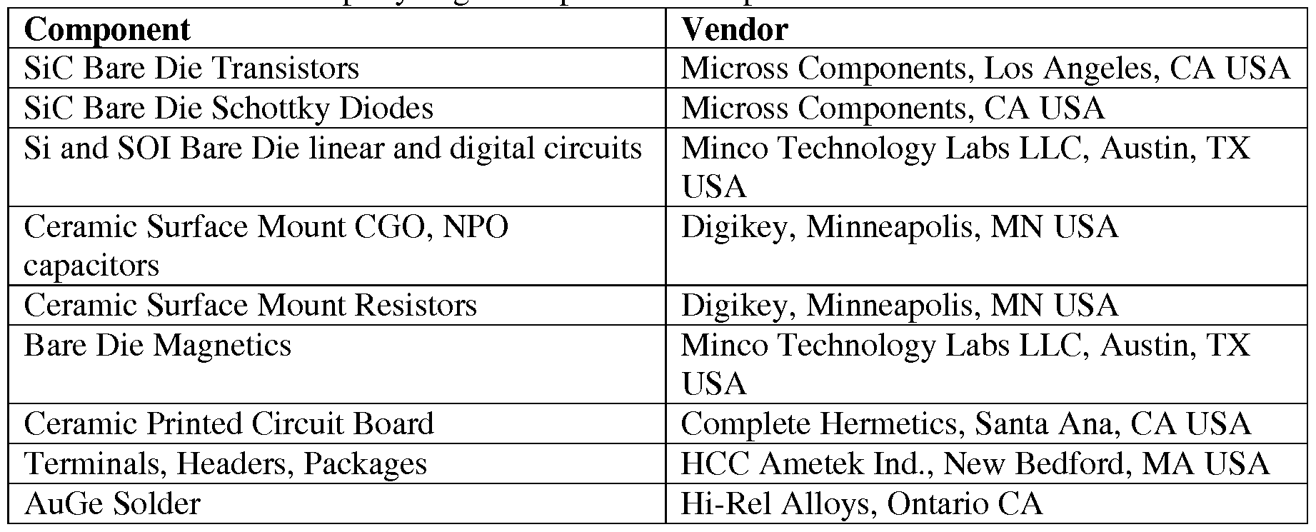
- Some exemplary off-the-shelf components and techniques that may be used in the power system 16 include: (1) bare die silicon and silicon-on-insulator active devices, (2) silicon carbide active power devices, (3) high temperature rated and low temperature coefficient ceramic passives (COG or NPO dielectrics), and (4) high temperature magnetic passives.
- A1N (aluminum nitride) ceramics may be used as a circuit substrate material for excellent thermal stability and thermal conductivity.
- Circuit interconnects may be formed of oxidation resistant Au traces. Bonding strategies may employ flip chip or Au or Al wire bonding for bare die active components using, for instance, AuGe high temperature solder. In some embodiments, wire bonding is expected to be advantageous over flip chip bonding due to the added mechanical compliance, especially in the presence of thermal expansion and shock and vibration.
- System peak power is calculated using the peak power of each cell, V w 2 /(4Rd C ), multiplied by the number of cells in the system, N.
- the maximum output current is calculated by dividing peak power by a nominal system voltage 20 V.
- System energy is calculated using the per cell energy, 1 ⁇ 2 CV w 2 /3,600, multiplied by the number of cells in the system, N.
Abstract
Description

Claims
Priority Applications (7)
| Application Number | Priority Date | Filing Date | Title |
|---|---|---|---|
| CA2838558A CA2838558C (en) | 2011-05-24 | 2012-05-24 | Power system for high temperature applications with rechargeable energy storage |
| EP20174829.0A EP3757348A1 (en) | 2011-05-24 | 2012-05-24 | Power system for high temperature applications with rechargeable energy storage |
| CN201280036518.XA CN104271880A (en) | 2011-05-24 | 2012-05-24 | Power system for high temperature applications with rechargeable energy storage |
| BR112013030106-6A BR112013030106B1 (en) | 2011-05-24 | 2012-05-24 | Power system adapted to supply power in a high temperature environment |
| EP12790090.0A EP2723979B1 (en) | 2011-05-24 | 2012-05-24 | Power system for high temperature applications with rechargeable energy storage |
| JP2014512104A JP2014525219A (en) | 2011-05-24 | 2012-05-24 | Power system for high temperature applications with rechargeable energy storage |
| AU2012258672A AU2012258672A1 (en) | 2011-05-24 | 2012-05-24 | Power system for high temperature applications with rechargeable energy storage |
Applications Claiming Priority (10)
| Application Number | Priority Date | Filing Date | Title |
|---|---|---|---|
| US201161489389P | 2011-05-24 | 2011-05-24 | |
| US61/489,389 | 2011-05-24 | ||
| US201161493039P | 2011-06-03 | 2011-06-03 | |
| US61/493,039 | 2011-06-03 | ||
| US201161494332P | 2011-06-07 | 2011-06-07 | |
| US61/494,332 | 2011-06-07 | ||
| US201161537360P | 2011-09-21 | 2011-09-21 | |
| US61/537,360 | 2011-09-21 | ||
| US201261620364P | 2012-04-04 | 2012-04-04 | |
| US61/620,364 | 2012-04-04 |
Publications (2)
| Publication Number | Publication Date |
|---|---|
| WO2012162500A2 true WO2012162500A2 (en) | 2012-11-29 |
| WO2012162500A3 WO2012162500A3 (en) | 2013-02-21 |
Family
ID=47218078
Family Applications (1)
| Application Number | Title | Priority Date | Filing Date |
|---|---|---|---|
| PCT/US2012/039342 WO2012162500A2 (en) | 2011-05-24 | 2012-05-24 | Power system for high temperature applications with rechargeable energy storage |
Country Status (8)
| Country | Link |
|---|---|
| US (6) | US9013144B2 (en) |
| EP (2) | EP3757348A1 (en) |
| JP (5) | JP2014525219A (en) |
| CN (1) | CN104271880A (en) |
| AU (1) | AU2012258672A1 (en) |
| BR (1) | BR112013030106B1 (en) |
| CA (1) | CA2838558C (en) |
| WO (1) | WO2012162500A2 (en) |
Cited By (36)
| Publication number | Priority date | Publication date | Assignee | Title |
|---|---|---|---|---|
| CN103236569A (en) * | 2013-05-02 | 2013-08-07 | 哈尔滨市德昌电气有限公司 | Electric vehicle power system and control method thereof |
| JP2014136927A (en) * | 2013-01-17 | 2014-07-28 | Sumitomo Electric Ind Ltd | Power supply system for winze |
| EP2808883A1 (en) * | 2013-05-30 | 2014-12-03 | Services Pétroliers Schlumberger | Thermal switch for downhole device |
| WO2015095858A3 (en) * | 2013-12-20 | 2015-09-03 | Fastcap Systems Corporation | Electromagnetic telemetry device |
| EP2965402A4 (en) * | 2013-03-07 | 2016-06-01 | Evolution Engineering Inc | System and method for charging a capacitor used to power measurement-while-drilling equipment |
| WO2016057983A3 (en) * | 2014-10-09 | 2016-06-30 | Fastcap Systems Corporation | Nanostructured electrode for energy storage device |
| JP2016521451A (en) * | 2013-03-15 | 2016-07-21 | ファーストキャップ・システムズ・コーポレイションFa | Modular signal interface device and associated wellbore power and data system |
| US9553336B2 (en) | 2013-11-15 | 2017-01-24 | Sumitomo Electric Industries, Ltd. | Power supply system for well |
| JP2017525870A (en) * | 2014-06-13 | 2017-09-07 | グリーンファイア・エナジー・インコーポレイテッドGreenfire Energy Inc | Geothermal loop energy production system |
| WO2017139692A3 (en) * | 2016-02-12 | 2017-09-21 | Capacitor Sciences Incorporated | Capacitive energy storage system |
| WO2017139284A3 (en) * | 2016-02-12 | 2017-09-28 | Capacitor Sciences Incorporated | Capacitive energy storage cell, module and system |
| US9899150B2 (en) | 2014-05-12 | 2018-02-20 | Capacitor Sciences Incorporated | Energy storage device and method of production thereof |
| US9916931B2 (en) | 2014-11-04 | 2018-03-13 | Capacitor Science Incorporated | Energy storage devices and methods of production thereof |
| US9932358B2 (en) | 2015-05-21 | 2018-04-03 | Capacitor Science Incorporated | Energy storage molecular material, crystal dielectric layer and capacitor |
| US9941051B2 (en) | 2015-06-26 | 2018-04-10 | Capactor Sciences Incorporated | Coiled capacitor |
| US9978517B2 (en) | 2016-04-04 | 2018-05-22 | Capacitor Sciences Incorporated | Electro-polarizable compound and capacitor |
| US10026553B2 (en) | 2015-10-21 | 2018-07-17 | Capacitor Sciences Incorporated | Organic compound, crystal dielectric layer and capacitor |
| EP3192154A4 (en) * | 2014-09-12 | 2018-09-12 | Saint-Augustin Canada Electric Inc. | Energy storage management system |
| US10153087B2 (en) | 2016-04-04 | 2018-12-11 | Capacitor Sciences Incorporated | Electro-polarizable compound and capacitor |
| CN109541285A (en) * | 2018-12-26 | 2019-03-29 | 东莞市长工微电子有限公司 | BuckBoost circuit output current detection method and its detection circuit |
| US10305295B2 (en) | 2016-02-12 | 2019-05-28 | Capacitor Sciences Incorporated | Energy storage cell, capacitive energy storage module, and capacitive energy storage system |
| US10319523B2 (en) | 2014-05-12 | 2019-06-11 | Capacitor Sciences Incorporated | Yanli dielectric materials and capacitor thereof |
| US10340082B2 (en) | 2015-05-12 | 2019-07-02 | Capacitor Sciences Incorporated | Capacitor and method of production thereof |
| US10347423B2 (en) | 2014-05-12 | 2019-07-09 | Capacitor Sciences Incorporated | Solid multilayer structure as semiproduct for meta-capacitor |
| US10395841B2 (en) | 2016-12-02 | 2019-08-27 | Capacitor Sciences Incorporated | Multilayered electrode and film energy storage device |
| EP3458677A4 (en) * | 2016-05-12 | 2020-02-26 | Baker Hughes, a GE company, LLC | Downhole component communication and power management |
| US10600582B1 (en) | 2016-12-02 | 2020-03-24 | Fastcap Systems Corporation | Composite electrode |
| US10636575B2 (en) | 2016-02-12 | 2020-04-28 | Capacitor Sciences Incorporated | Furuta and para-Furuta polymer formulations and capacitors |
| US10714271B2 (en) | 2011-07-08 | 2020-07-14 | Fastcap Systems Corporation | High temperature energy storage device |
| US10830034B2 (en) | 2011-11-03 | 2020-11-10 | Fastcap Systems Corporation | Production logging instrument |
| US10872737B2 (en) | 2013-10-09 | 2020-12-22 | Fastcap Systems Corporation | Advanced electrolytes for high temperature energy storage device |
| US10872733B2 (en) | 2016-04-04 | 2020-12-22 | Capacitor Sciences Incorporated | YanLi material and dielectric and capacitor thereof |
| US11127537B2 (en) | 2015-01-27 | 2021-09-21 | Fastcap Systems Corporation | Wide temperature range ultracapacitor |
| US11250995B2 (en) | 2011-07-08 | 2022-02-15 | Fastcap Systems Corporation | Advanced electrolyte systems and their use in energy storage devices |
| US11270850B2 (en) | 2013-12-20 | 2022-03-08 | Fastcap Systems Corporation | Ultracapacitors with high frequency response |
| US11557765B2 (en) | 2019-07-05 | 2023-01-17 | Fastcap Systems Corporation | Electrodes for energy storage devices |
Families Citing this family (104)
| Publication number | Priority date | Publication date | Assignee | Title |
|---|---|---|---|---|
| WO2010068929A2 (en) * | 2008-12-12 | 2010-06-17 | Ionix Power Systems | Active electrolyte electrochemical capacitor |
| US8829905B2 (en) * | 2010-05-25 | 2014-09-09 | General Electric Company | Magnetic resonance imaging compatible switched mode power supply |
| EP3757348A1 (en) * | 2011-05-24 | 2020-12-30 | FastCAP SYSTEMS Corporation | Power system for high temperature applications with rechargeable energy storage |
| EA201490346A1 (en) * | 2011-07-27 | 2015-02-27 | Фасткэп Системз Корпорейшн | POWER SUPPLY FOR WELL TOOLING |
| JP6042148B2 (en) * | 2011-11-22 | 2016-12-14 | 東芝メディカルシステムズ株式会社 | Magnetic resonance imaging system |
| EP2826095A2 (en) * | 2012-03-13 | 2015-01-21 | Maxwell Technologies, Inc. | Capacitor and battery combination |
| ITCO20120015A1 (en) | 2012-04-12 | 2013-10-13 | Nuovo Pignone Srl | METHOD FOR THE PREVENTION OF CORROSION AND COMPONENT OBTAINED THROUGH THIS METHOD |
| TWI467885B (en) * | 2012-10-19 | 2015-01-01 | 廣達電腦股份有限公司 | Electronic devices and electronic systems |
| FR3000264B1 (en) * | 2012-12-20 | 2015-02-27 | Commissariat Energie Atomique | HIGH TEMPERATURE BATTERY MANAGEMENT |
| US20150346752A1 (en) * | 2012-12-21 | 2015-12-03 | Shell Oil Company | Combination power source for instrumented sensor subsystems |
| JP2014137938A (en) * | 2013-01-17 | 2014-07-28 | Sumitomo Electric Ind Ltd | Molten salt battery, and power supply system |
| US9631484B2 (en) * | 2013-02-17 | 2017-04-25 | R&B Industrial Supply Co. | Drilling system having a super-capacitor amplifier and a method for transmitting signals |
| CN104008882B (en) | 2013-02-22 | 2018-03-27 | 王海 | High pressure pulse discharge capacitor and preparation method thereof |
| US9512716B2 (en) * | 2013-03-05 | 2016-12-06 | Evolution Engineering Inc. | System and method for regulating an electromagnetic telemetry signal sent from downhole to surface |
| KR102201102B1 (en) * | 2013-03-15 | 2021-01-12 | 디자인 플럭스 테크놀로지스, 엘엘씨 | Method and apparatus for creating a dynamically reconfigurable energy storage device |
| US20190218894A9 (en) * | 2013-03-15 | 2019-07-18 | Fastcap Systems Corporation | Power system for downhole toolstring |
| US9816325B2 (en) * | 2013-04-19 | 2017-11-14 | Schlumberger Technology Corporation | Isolation adapter for using multiple power sources in a bottom hole assembly |
| US9461469B2 (en) * | 2013-05-31 | 2016-10-04 | Schlumberger Technology Corporation | Electrical power grid for a downhole BHA |
| US10145210B2 (en) * | 2013-06-19 | 2018-12-04 | Baker Hughes, A Ge Company, Llc | Hybrid battery for high temperature applications |
| KR101500358B1 (en) * | 2013-07-08 | 2015-03-18 | 현대자동차 주식회사 | System and method for controlling state of charge of battery in vehicle |
| JP2015065795A (en) * | 2013-09-26 | 2015-04-09 | ソニー株式会社 | Power storage, power storage controller and power storage control method |
| WO2015054432A1 (en) * | 2013-10-08 | 2015-04-16 | Fastcap Systems Corporation | Dynamics monitoring system with rotational sensor |
| AU2013404986B2 (en) * | 2013-11-05 | 2017-07-27 | Halliburton Energy Services, Inc. | Bulk capacitor charging circuit for mud pulse telemetry device |
| CN103716002A (en) * | 2013-12-20 | 2014-04-09 | 中国北方车辆研究所 | Apparatus for realizing wireless transmission tuning antenna matching |
| DK3101770T3 (en) * | 2014-01-28 | 2019-07-22 | Guangdong Oppo Mobile Telecommunications Corp Ltd | POWER ADAPTERS AND TERMINAL |
| DK3101437T3 (en) | 2014-01-28 | 2019-05-06 | Guangdong Oppo Mobile Telecommunications Corp Ltd | POWER ADAPTERS, TERMINAL AND METHOD OF HANDLING IMPEDANCE DIFFERENCE IN A CHARGING LOOP |
| WO2015113466A1 (en) * | 2014-01-28 | 2015-08-06 | 广东欧珀移动通信有限公司 | Power adapter, terminal, and method for processing exception of charging loop |
| US9856722B2 (en) | 2014-03-14 | 2018-01-02 | General Electric Company | Methods and systems for controlling voltage switching |
| DE102014206470A1 (en) * | 2014-04-03 | 2015-10-08 | Msa Europe Gmbh | Method for depassivating a lithium thionyl battery, a device for carrying out the method and a battery device |
| JP6090265B2 (en) * | 2014-08-29 | 2017-03-08 | トヨタ自動車株式会社 | vehicle |
| WO2016039900A1 (en) * | 2014-09-12 | 2016-03-17 | Exxonmobil Upstream Research Comapny | Discrete wellbore devices, hydrocarbon wells including a downhole communication network and the discrete wellbore devices and systems and methods including the same |
| US9593557B2 (en) * | 2014-09-25 | 2017-03-14 | Chevron U.S.A. Inc | System and method for autonomous downhole power generation |
| US9927274B2 (en) * | 2014-11-24 | 2018-03-27 | Jabil Inc. | Non-invasive fluid flow detection using digital accelerometers |
| US10431858B2 (en) | 2015-02-04 | 2019-10-01 | Global Web Horizons, Llc | Systems, structures and materials for electrochemical device thermal management |
| EP3283859B1 (en) * | 2015-04-17 | 2020-02-12 | Micatu Inc. | Enhanced optical condition monitoring system for power transformer and method for operating power transformer |
| CN106329898B (en) | 2015-06-19 | 2021-09-14 | 康普技术有限责任公司 | Quick discharge circuit and discharge method for soft start circuit |
| US20160380247A1 (en) * | 2015-06-25 | 2016-12-29 | Iontensity, LLC | Battery Packs Having Single Stacks of Battery Cells |
| JP6401668B2 (en) * | 2015-06-29 | 2018-10-10 | Kyb株式会社 | Control system and control method for hybrid construction machine |
| US10672578B2 (en) * | 2015-08-26 | 2020-06-02 | David Stuckey Investments Pty Ltd | Solid-state relay |
| US10090766B2 (en) * | 2015-11-11 | 2018-10-02 | Halliburton Energy Services, Inc. | Reusing electromagnetic energy from a voltage converter downhole |
| US10983246B2 (en) * | 2015-12-21 | 2021-04-20 | Schlumberger Technology Corporation | Thermal maturity estimation via logs |
| US10224579B2 (en) * | 2015-12-31 | 2019-03-05 | Robert Bosch Gmbh | Evaluating capacity fade in dual insertion batteries using potential and temperature measurements |
| DE102016100341A1 (en) * | 2016-01-11 | 2017-07-13 | Wincor Nixdorf International Gmbh | Method and device for depassivating a battery of a valuable container |
| JP6569540B2 (en) * | 2016-01-13 | 2019-09-04 | 株式会社Gsユアサ | In-vehicle power supply system and battery state detection method included therein |
| US10263447B2 (en) | 2016-01-29 | 2019-04-16 | Robert Bosch Gmbh | Secondary battery management system |
| US10686321B2 (en) | 2016-01-29 | 2020-06-16 | Robert Bosch Gmbh | Secondary battery management |
| DE102016202443B3 (en) * | 2016-02-17 | 2017-05-18 | Siemens Healthcare Gmbh | Circuit arrangement, gradient amplifier and method for compensation of non-linearities of an amplifier output stage |
| US10118696B1 (en) | 2016-03-31 | 2018-11-06 | Steven M. Hoffberg | Steerable rotating projectile |
| MY192979A (en) | 2016-05-20 | 2022-09-20 | Kyocera Avx Components Corp | System and method for charging a capacitor |
| EP3252268A1 (en) * | 2016-06-02 | 2017-12-06 | Welltec A/S | Downhole power supply device |
| US10753191B2 (en) | 2016-06-28 | 2020-08-25 | Baker Hughes, A Ge Company, Llc | Downhole tools with power utilization apparatus during flow-off state |
| WO2018005409A1 (en) * | 2016-06-30 | 2018-01-04 | Westerngeco Llc | Seismic sensor assembly overvoltage protection circuitry |
| CN107617806B (en) * | 2016-07-15 | 2020-08-04 | 上海沪工焊接集团股份有限公司 | Welding machine control circuit |
| US10954005B1 (en) * | 2016-07-25 | 2021-03-23 | Space Systems/Loral, Llc | Power train for deep space solar electric propulsion |
| CA3028626C (en) | 2016-08-09 | 2022-05-31 | Halliburton Energy Services, Inc. | Depassivation of completion tool batteries |
| WO2018038911A1 (en) | 2016-08-26 | 2018-03-01 | General Electric Company | Power conversion system and an associated method thereof |
| GB2565729B (en) * | 2016-09-28 | 2021-07-28 | Halliburton Energy Services Inc | Extended power system for downhole tools |
| US11830672B2 (en) | 2016-11-23 | 2023-11-28 | KYOCERA AVX Components Corporation | Ultracapacitor for use in a solder reflow process |
| CN106655440B (en) * | 2016-12-06 | 2019-06-11 | 武汉工程大学 | The method of the super capacitor and accumulator hybrid energy-storing system and energy absorption and release of two-stage series connection |
| US10072495B1 (en) * | 2017-03-13 | 2018-09-11 | Saudi Arabian Oil Company | Systems and methods for wirelessly monitoring well conditions |
| US10914777B2 (en) * | 2017-03-24 | 2021-02-09 | Rosemount Aerospace Inc. | Probe heater remaining useful life determination |
| US11060992B2 (en) | 2017-03-24 | 2021-07-13 | Rosemount Aerospace Inc. | Probe heater remaining useful life determination |
| US10564203B2 (en) | 2017-03-24 | 2020-02-18 | Rosemount Aerospace Inc. | Probe heater remaining useful life determination |
| US10895592B2 (en) | 2017-03-24 | 2021-01-19 | Rosemount Aerospace Inc. | Probe heater remaining useful life determination |
| CN108736463A (en) * | 2017-04-24 | 2018-11-02 | 通用电气公司 | Generating power downhole system and method |
| CN107159068B (en) * | 2017-06-21 | 2020-05-22 | 北京石油化工学院 | Preparation method of graphene composite aerogel |
| CN109281661B (en) * | 2017-07-19 | 2021-09-14 | 中国石油化工股份有限公司 | Quantitative evaluation method and device for double-laterolog |
| US10620229B2 (en) * | 2017-08-25 | 2020-04-14 | Nxp B.V. | Magnetic field sensor systems and method of determining operability of same |
| JP2020533790A (en) * | 2017-09-07 | 2020-11-19 | エイブイエックス コーポレイション | Supercapacitor module with matched supercapacitor |
| US10749373B2 (en) * | 2017-09-29 | 2020-08-18 | Fisher Controls International Llc | Systems and methods for situation-dependent supercapacitor voltage control |
| JP7358343B2 (en) | 2017-10-03 | 2023-10-10 | ファーストキャップ・システムズ・コーポレイション | Chip type ultracapacitor |
| TWI668562B (en) * | 2017-11-09 | 2019-08-11 | 新唐科技股份有限公司 | System on chip |
| WO2019113694A1 (en) * | 2017-12-13 | 2019-06-20 | Mwdplanet And Lumen Corporation | Electromagnetic telemetry transmitter apparatus and mud pulse-electromagnetic telemetry assembly |
| CN108386168B (en) * | 2018-03-02 | 2023-10-31 | 浙江聚能电气科技有限公司 | Device for heavy oil exploitation by utilizing energy-gathering pulse and application method thereof |
| JP6984498B2 (en) | 2018-03-09 | 2021-12-22 | トヨタ自動車株式会社 | Vehicle driving system |
| US11712637B1 (en) | 2018-03-23 | 2023-08-01 | Steven M. Hoffberg | Steerable disk or ball |
| US10677620B2 (en) | 2018-05-01 | 2020-06-09 | Nxp B.V. | System and method for sensor diagnostics during functional operation |
| CN109083623B (en) * | 2018-08-23 | 2021-01-05 | 东北石油大学 | Intelligent underground layered water injection flow adjusting system |
| US11251637B2 (en) | 2018-12-04 | 2022-02-15 | Mobile Escapes, Llc | Mobile power system with multiple converters and related platforms and methods |
| US11061080B2 (en) | 2018-12-14 | 2021-07-13 | Rosemount Aerospace Inc. | Real time operational leakage current measurement for probe heater PHM and prediction of remaining useful life |
| US10962580B2 (en) | 2018-12-14 | 2021-03-30 | Rosemount Aerospace Inc. | Electric arc detection for probe heater PHM and prediction of remaining useful life |
| CN109659634B (en) * | 2018-12-18 | 2021-03-09 | 安徽江淮汽车集团股份有限公司 | Compact battery cut-off unit |
| EP4343271A2 (en) * | 2019-02-28 | 2024-03-27 | Halliburton Energy Services, Inc. | Power bottom hole assembly via a powered drill string |
| WO2020180317A1 (en) * | 2019-03-06 | 2020-09-10 | Johnson Controls Fire Protection LP | Lithium battery passivation detection |
| CN110011411A (en) * | 2019-03-08 | 2019-07-12 | 国网浙江省电力有限公司 | The intelligent distribution transformer terminals of low-voltage power distribution station area |
| US11316217B2 (en) * | 2019-05-09 | 2022-04-26 | GM Global Technology Operations LLC | Configurable thermal conditioning of battery cells |
| US11639954B2 (en) | 2019-05-29 | 2023-05-02 | Rosemount Aerospace Inc. | Differential leakage current measurement for heater health monitoring |
| US11472562B2 (en) | 2019-06-14 | 2022-10-18 | Rosemount Aerospace Inc. | Health monitoring of an electrical heater of an air data probe |
| GB201908929D0 (en) * | 2019-06-21 | 2019-08-07 | Expro North Sea Ltd | Power and telemetry systems for a downhole instrument |
| US11930563B2 (en) | 2019-09-16 | 2024-03-12 | Rosemount Aerospace Inc. | Monitoring and extending heater life through power supply polarity switching |
| US11349191B1 (en) * | 2019-09-17 | 2022-05-31 | Amazon Technologies, Inc. | Ring-shaped devices with combined battery and antenna assemblies |
| CN110630253B (en) * | 2019-09-18 | 2020-11-06 | 中国科学院地质与地球物理研究所 | Near-bit wireless short-transmission constant current transmitting method and device |
| CN110907042B (en) * | 2019-11-21 | 2021-02-23 | 深圳供电局有限公司 | Transformer temperature rise monitoring device and system |
| CN110867965A (en) * | 2019-11-27 | 2020-03-06 | 黄河科技学院 | Intelligent detection system for transformer substation computer monitoring system |
| CN110952425B (en) * | 2019-12-19 | 2021-06-01 | 长沙理工大学 | Working method of paving and rolling construction monitoring device |
| CN110994993B (en) * | 2019-12-30 | 2021-01-29 | 施耐德电气(中国)有限公司 | Multichannel bidirectional buck-boost circuit |
| CN111293753B (en) * | 2020-03-19 | 2021-07-27 | 上海度普新能源科技有限公司 | Fault processing method and system for charging gun |
| US11293995B2 (en) | 2020-03-23 | 2022-04-05 | Rosemount Aerospace Inc. | Differential leakage current measurement for heater health monitoring |
| US11630140B2 (en) | 2020-04-22 | 2023-04-18 | Rosemount Aerospace Inc. | Prognostic health monitoring for heater |
| CN111613743A (en) * | 2020-04-27 | 2020-09-01 | 中国石油天然气集团有限公司 | High-temperature and high-pressure resistant storage type logging instrument rechargeable power supply short section and charging and discharging method |
| CN112580289B (en) * | 2020-12-04 | 2024-03-19 | 华中科技大学 | Hybrid capacitor power state online estimation method and system |
| US11905799B2 (en) * | 2021-07-18 | 2024-02-20 | Cnpc Usa Corporation | Hybrid battery pack system |
| WO2023239270A1 (en) * | 2022-06-10 | 2023-12-14 | Epiroc Rock Drills Aktiebolag | Control system, control unit and method therein for handling a condition of an energy storage |
| CN115345208B (en) * | 2022-10-19 | 2023-02-03 | 成都理工大学 | Neutron-gamma pulse accumulation discrimination method based on top-hat conversion |
Family Cites Families (144)
| Publication number | Priority date | Publication date | Assignee | Title |
|---|---|---|---|---|
| US3982182A (en) | 1973-08-13 | 1976-09-21 | Coulter Electronics, Inc. | Conductivity cell for particle study device |
| US4408259A (en) | 1979-02-09 | 1983-10-04 | Matsushita Electric Industrial Company, Limited | Electrochemical double-layer capacitor |
| US4349910A (en) | 1979-09-28 | 1982-09-14 | Union Carbide Corporation | Method and apparatus for orientation of electrode joint threads |
| US4839248A (en) * | 1988-01-15 | 1989-06-13 | Rainin Instrument Co., Inc. | System and method for depassivating a passivated lithium battery in a battery powered microprocessor controlled device |
| US4934366A (en) | 1988-09-01 | 1990-06-19 | Siemens-Pacesetter, Inc. | Feedthrough connector for implantable medical device |
| NL9001976A (en) | 1990-09-07 | 1992-04-01 | Kinetron Bv | GENERATOR. |
| JPH05234814A (en) * | 1992-02-24 | 1993-09-10 | Murata Mfg Co Ltd | Electric double layer capacitor |
| CH686206A5 (en) | 1992-03-26 | 1996-01-31 | Asulab Sa | Cellule photoelectrochimique regeneratrice transparent. |
| US5476709A (en) | 1992-06-15 | 1995-12-19 | Mitsui Toatsu Chemicals, Inc. | Polymeric insulating material and formed article making use of the material |
| EP0662248A4 (en) * | 1992-09-18 | 2000-10-25 | Pinnacle Research Inst Inc | Energy storage device and methods of manufacture |
| US5711988A (en) | 1992-09-18 | 1998-01-27 | Pinnacle Research Institute, Inc. | Energy storage device and its methods of manufacture |
| US5440447A (en) | 1993-07-02 | 1995-08-08 | The Morgan Crucible Company, Plc | High temperature feed-through system and method for making same |
| US5621607A (en) | 1994-10-07 | 1997-04-15 | Maxwell Laboratories, Inc. | High performance double layer capacitors including aluminum carbon composite electrodes |
| RU98120524A (en) | 1996-05-15 | 2000-10-10 | Хайперион Каталайзис Интернэшнл | GRAPHITE NANOFIBERS IN ELECTROCHEMICAL CAPACITORS |
| EP0948828B1 (en) * | 1996-08-19 | 2001-06-06 | Siemens Aktiengesellschaft Österreich | Method and circuit for depassivation of a battery |
| BR9807239A (en) | 1997-02-19 | 2000-04-25 | Starck H C Gmbh Co Kg | Tantalum powders, processes for their preparation, as well as sintering anodes prepared from them |
| US6683783B1 (en) | 1997-03-07 | 2004-01-27 | William Marsh Rice University | Carbon fibers formed from single-wall carbon nanotubes |
| US6205016B1 (en) | 1997-06-04 | 2001-03-20 | Hyperion Catalysis International, Inc. | Fibril composite electrode for electrochemical capacitors |
| US6045941A (en) * | 1997-07-08 | 2000-04-04 | Schlumberger Technology Corporation | Method to determine the state of charge and remaining life of lithium batteries used in oilfield services applications |
| US6843119B2 (en) | 1997-09-18 | 2005-01-18 | Solinst Canada Limited | Apparatus for measuring and recording data from boreholes |
| US6511760B1 (en) | 1998-02-27 | 2003-01-28 | Restek Corporation | Method of passivating a gas vessel or component of a gas transfer system using a silicon overlay coating |
| US6247533B1 (en) | 1998-03-09 | 2001-06-19 | Seismic Recovery, Llc | Utilization of energy from flowing fluids |
| US6141205A (en) | 1998-04-03 | 2000-10-31 | Medtronic, Inc. | Implantable medical device having flat electrolytic capacitor with consolidated electrode tabs and corresponding feedthroughs |
| JP2000100672A (en) | 1998-09-22 | 2000-04-07 | Okamura Kenkyusho:Kk | Manufacture of electric double layer capacitor |
| US6201685B1 (en) | 1998-10-05 | 2001-03-13 | General Electric Company | Ultracapacitor current collector |
| US6232706B1 (en) | 1998-11-12 | 2001-05-15 | The Board Of Trustees Of The Leland Stanford Junior University | Self-oriented bundles of carbon nanotubes and method of making same |
| US6118251A (en) * | 1999-01-27 | 2000-09-12 | The United States Of America As Represented By The Secretary Of The Army | Battery depassivation and conditioning method and apparatus |
| US6444326B1 (en) | 1999-03-05 | 2002-09-03 | Restek Corporation | Surface modification of solid supports through the thermal decomposition and functionalization of silanes |
| WO2004030120A2 (en) | 1999-04-08 | 2004-04-08 | Quallion Llc | Battery case, cover and feedthrough |
| EP1059266A3 (en) | 1999-06-11 | 2000-12-20 | Iljin Nanotech Co., Ltd. | Mass synthesis method of high purity carbon nanotubes vertically aligned over large-size substrate using thermal chemical vapor deposition |
| EP1061554A1 (en) | 1999-06-15 | 2000-12-20 | Iljin Nanotech Co., Ltd. | White light source using carbon nanotubes and fabrication method thereof |
| US6449139B1 (en) | 1999-08-18 | 2002-09-10 | Maxwell Electronic Components Group, Inc. | Multi-electrode double layer capacitor having hermetic electrolyte seal |
| US6257332B1 (en) | 1999-09-14 | 2001-07-10 | Halliburton Energy Services, Inc. | Well management system |
| JP2001160525A (en) | 1999-09-24 | 2001-06-12 | Honda Motor Co Ltd | Pretreatment method of active carbon for polarized electrode |
| TW497286B (en) | 1999-09-30 | 2002-08-01 | Canon Kk | Rechargeable lithium battery and process for the production thereof |
| US6413285B1 (en) | 1999-11-01 | 2002-07-02 | Polyplus Battery Company | Layered arrangements of lithium electrodes |
| US6304427B1 (en) | 2000-01-07 | 2001-10-16 | Kemet Electronics Corporation | Combinations of materials to minimize ESR and maximize ESR stability of surface mount valve-metal capacitors after exposure to heat and/or humidity |
| US6679332B2 (en) | 2000-01-24 | 2004-01-20 | Shell Oil Company | Petroleum well having downhole sensors, communication and power |
| KR100487069B1 (en) | 2000-04-12 | 2005-05-03 | 일진나노텍 주식회사 | Supercapacitor using electrode of new material and manufacturing method the same |
| US6388423B1 (en) * | 2001-02-23 | 2002-05-14 | John W. Schilleci, Jr. | Battery monitor and open circuit protector |
| JP2002270235A (en) | 2001-03-07 | 2002-09-20 | Nisshinbo Ind Inc | Pregel component for polymer gel electrolyte and dehidrating method of the same, secondary cell and electric double layer capacitor |
| US6872681B2 (en) | 2001-05-18 | 2005-03-29 | Hyperion Catalysis International, Inc. | Modification of nanotubes oxidation with peroxygen compounds |
| US6497974B2 (en) * | 2001-05-23 | 2002-12-24 | Avista Laboratories, Inc. | Fuel cell power system, method of distributing power, and method of operating a fuel cell power system |
| JP2003045759A (en) | 2001-07-30 | 2003-02-14 | Meidensha Corp | Improvement method of self-discharging characteristics of electric double-layer capacitor |
| JP2003089371A (en) * | 2001-09-17 | 2003-03-25 | Honda Motor Co Ltd | Light-emission device for vehicle |
| JP2003173936A (en) | 2001-09-28 | 2003-06-20 | Sanyo Chem Ind Ltd | Electrolyte solution for electrochemical capacitor and electrochemical capacitor using the same |
| US20080068801A1 (en) | 2001-10-04 | 2008-03-20 | Ise Corporation | High-Power Ultracapacitor Energy Storage Cell Pack and Coupling Method |
| JP2003115422A (en) * | 2001-10-05 | 2003-04-18 | Nissan Diesel Motor Co Ltd | Method of manufacturing electric double layer capacitor |
| JP3941917B2 (en) | 2001-10-19 | 2007-07-11 | Necトーキン株式会社 | Electric double layer capacitor manufacturing method and electric double layer capacitor |
| ATE502414T1 (en) | 2002-01-09 | 2011-04-15 | Eco Bat Indiana Llc | METHOD FOR REMOVAL OF AN ELECTROLYTE FROM AN ENERGY STORAGE AND/OR A SUPERCRITICAL FLUID CONVERSION DEVICE |
| CA2367290A1 (en) | 2002-01-16 | 2003-07-16 | Hydro Quebec | High stability polymer electrolyte > 4 volts as electrolyte for a hybrid supercondenser and electrochemical generator |
| US6872645B2 (en) | 2002-04-02 | 2005-03-29 | Nanosys, Inc. | Methods of positioning and/or orienting nanostructures |
| US7709415B2 (en) | 2002-04-22 | 2010-05-04 | Kuraray Chemical Co., Ltd. | Method for manufacturing activated carbon, polarizable electrode, and electric double-layered capacitor |
| US7335395B2 (en) | 2002-04-23 | 2008-02-26 | Nantero, Inc. | Methods of using pre-formed nanotubes to make carbon nanotube films, layers, fabrics, ribbons, elements and articles |
| US7452452B2 (en) | 2002-04-29 | 2008-11-18 | The Trustees Of Boston College | Carbon nanotube nanoelectrode arrays |
| JP4439797B2 (en) * | 2002-10-03 | 2010-03-24 | 株式会社日本触媒 | Ion conductor materials |
| EP1411533A1 (en) | 2002-10-09 | 2004-04-21 | Asahi Glass Company, Limited | Electric double layer capacitor and process for its production |
| WO2004040605A1 (en) | 2002-10-31 | 2004-05-13 | Mitsubishi Chemical Corporation | Electrolyte for electrolytic capacitor, electrolytic capacitor and process for producing tetrafluoroaluminate salt of organic onium |
| DE10250808B3 (en) | 2002-10-31 | 2004-04-08 | Honeywell Specialty Chemicals Seelze Gmbh | Preparation of electrolyte containing tetraalkylammonium tetrafluoroborate, used in electrochemical cell or capacitor, involves mixing tetraalkylammonium halide and metal tetrafluoroborate in (partly) water-miscible organic solvent |
| JP2004207451A (en) | 2002-12-25 | 2004-07-22 | Sanyo Chem Ind Ltd | Electrolyte |
| KR100675366B1 (en) | 2002-12-30 | 2007-01-29 | 주식회사 네스캡 | Electric energy storage device and method of charging and discharging the same |
| TWI236778B (en) | 2003-01-06 | 2005-07-21 | Hon Hai Prec Ind Co Ltd | Lithium ion battery |
| US6764874B1 (en) | 2003-01-30 | 2004-07-20 | Motorola, Inc. | Method for chemical vapor deposition of single walled carbon nanotubes |
| AU2003900633A0 (en) | 2003-02-13 | 2003-02-27 | Energy Storage Systems Pty Ltd | A resistive balance for an energy storage device |
| US7070833B2 (en) | 2003-03-05 | 2006-07-04 | Restek Corporation | Method for chemical vapor deposition of silicon on to substrates for use in corrosive and vacuum environments |
| DE10313207A1 (en) | 2003-03-25 | 2004-10-07 | Basf Ag | Cleaning or processing ionic liquids with adsorptive separation processes |
| US7009363B2 (en) * | 2003-03-26 | 2006-03-07 | Pathfinder Energy Services, Inc. | Optimized battery life in multiple battery applications |
| KR100873426B1 (en) | 2003-03-31 | 2008-12-11 | 도요 알루미늄 가부시키가이샤 | Foil for negative electrode of capacitor and process for producing the same |
| US20040229117A1 (en) | 2003-05-14 | 2004-11-18 | Masaya Mitani | Electrochemical cell stack |
| US6914341B1 (en) | 2003-07-29 | 2005-07-05 | Mcintyre Stephen | Rotational inertia aided electric generator |
| US7201627B2 (en) | 2003-07-31 | 2007-04-10 | Semiconductor Energy Laboratory, Co., Ltd. | Method for manufacturing ultrafine carbon fiber and field emission element |
| CN100399480C (en) * | 2003-09-30 | 2008-07-02 | 清华大学深圳研究生院 | Stacked super condensor and its manufacturing method |
| JP4415673B2 (en) | 2003-12-26 | 2010-02-17 | Tdk株式会社 | Capacitor electrode manufacturing method |
| BRPI0418225A (en) | 2003-12-29 | 2007-04-27 | Shell Int Research | electrochemical element, and method for providing electrical energy in an underground wellbore |
| US7017417B2 (en) * | 2004-02-10 | 2006-03-28 | Weatherford/Lamb, Inc. | Pressure sensor assembly suitable for use in harsh environments |
| JP2005234814A (en) * | 2004-02-18 | 2005-09-02 | Fujitsu Ltd | Program, program construction method, storage medium, program construction system and terminal equipment |
| US7999695B2 (en) | 2004-03-03 | 2011-08-16 | Halliburton Energy Services, Inc. | Surface real-time processing of downhole data |
| US7521153B2 (en) | 2004-03-16 | 2009-04-21 | Toyota Motor Engineering & Manufacturing North America, Inc. | Corrosion protection using protected electron collector |
| US20050231893A1 (en) | 2004-04-19 | 2005-10-20 | Harvey Troy A | Electric double layer capacitor enclosed in polymer housing |
| JP4379247B2 (en) | 2004-04-23 | 2009-12-09 | 住友電気工業株式会社 | Method for producing carbon nanostructure |
| US20050238810A1 (en) | 2004-04-26 | 2005-10-27 | Mainstream Engineering Corp. | Nanotube/metal substrate composites and methods for producing such composites |
| GB0412314D0 (en) * | 2004-06-02 | 2004-07-07 | Glaxo Group Ltd | Compounds |
| US8277984B2 (en) | 2006-05-02 | 2012-10-02 | The Penn State Research Foundation | Substrate-enhanced microbial fuel cells |
| US7245478B2 (en) | 2004-08-16 | 2007-07-17 | Maxwell Technologies, Inc. | Enhanced breakdown voltage electrode |
| US20080090183A1 (en) | 2004-10-22 | 2008-04-17 | Lingbo Zhu | Aligned Carbon Nanotubes And Method For Construction Thereof |
| KR100627313B1 (en) | 2004-11-30 | 2006-09-25 | 삼성에스디아이 주식회사 | Secondary battery |
| US7717167B2 (en) * | 2004-12-03 | 2010-05-18 | Halliburton Energy Services, Inc. | Switchable power allocation in a downhole operation |
| WO2006060673A1 (en) * | 2004-12-03 | 2006-06-08 | Halliburton Energy Services, Inc. | Rechargeable energy storage device in a downhole operation |
| DE102004058907A1 (en) | 2004-12-07 | 2006-06-08 | Basf Ag | Purification of ionic liquids |
| US7667942B2 (en) * | 2004-12-13 | 2010-02-23 | Schlumberger Technology Corporation | Battery switch for downhole tools |
| US7381367B1 (en) | 2005-03-21 | 2008-06-03 | Catalytic Materials, Llc | Aluminum electrolytic capacitor having an anode having a uniform array of micron-sized pores |
| US7126207B2 (en) | 2005-03-24 | 2006-10-24 | Intel Corporation | Capacitor with carbon nanotubes |
| US7800886B2 (en) | 2005-04-12 | 2010-09-21 | Sumitomo Chemical Company, Limited | Electric double layer capacitor |
| US7817404B2 (en) | 2005-04-20 | 2010-10-19 | Panasonic Corporation | Capacitor and method for manufacturing same |
| US20060256506A1 (en) | 2005-04-27 | 2006-11-16 | Showa Denko K.K. | Solid electrolyte capacitor and process for producing same |
| US8164307B2 (en) * | 2005-05-27 | 2012-04-24 | Savi Technology, Inc. | Method and apparatus for monitoring the voltage of a battery |
| WO2006130511A1 (en) | 2005-05-31 | 2006-12-07 | Corning Incorporated | Cellular honeycomb ultracapacitors and hybrid capacitors and methods for producing |
| US7271994B2 (en) | 2005-06-08 | 2007-09-18 | Greatbatch Ltd. | Energy dense electrolytic capacitor |
| US7511941B1 (en) | 2005-06-08 | 2009-03-31 | Maxwell Technologies, Inc. | Ultrasonic sealed fill hole |
| TWI367511B (en) | 2005-06-10 | 2012-07-01 | Japan Gore Tex Inc | Electrode for electric double layer capacitor and electric double layer capacitor |
| US7475593B2 (en) * | 2005-06-24 | 2009-01-13 | Precision Energy Services, Inc. | High temperature near infrared for measurements and telemetry in well boreholes |
| US8563166B2 (en) | 2005-07-29 | 2013-10-22 | Seiko Instruments Inc. | Electrochemical cell |
| US7466539B2 (en) | 2005-09-30 | 2008-12-16 | Wisconsin Alumni Research Foundation | Electrochemical double-layer capacitor using organosilicon electrolytes |
| WO2007062125A1 (en) | 2005-11-22 | 2007-05-31 | Maxwell Technologies, Inc. | Ultracapacitor pressure control system |
| JP5179015B2 (en) * | 2005-12-13 | 2013-04-10 | パナソニック株式会社 | Capacitor |
| US7692411B2 (en) | 2006-01-05 | 2010-04-06 | Tpl, Inc. | System for energy harvesting and/or generation, storage, and delivery |
| JP4817296B2 (en) | 2006-01-06 | 2011-11-16 | 独立行政法人産業技術総合研究所 | Aligned carbon nanotube bulk aggregate and method for producing the same |
| CN101375431B (en) | 2006-01-30 | 2011-02-02 | 京瓷株式会社 | Container for electricity accumulator and battery and electric double layer capacitor employing same |
| WO2008054839A2 (en) | 2006-03-03 | 2008-05-08 | William Marsh Rice University | Carbon nanotube diameter selection by pretreatment of metal catalysts on surfaces |
| US8475676B2 (en) | 2006-03-08 | 2013-07-02 | Cap-Xx Limited | Electrolyte |
| US20070258192A1 (en) | 2006-05-05 | 2007-11-08 | Joel Schindall | Engineered structure for charge storage and method of making |
| US7990679B2 (en) | 2006-07-14 | 2011-08-02 | Dais Analytic Corporation | Nanoparticle ultracapacitor |
| WO2008013095A1 (en) | 2006-07-27 | 2008-01-31 | Nichicon Corporation | Ionic compound |
| US8284539B2 (en) | 2006-08-02 | 2012-10-09 | Ada Technologies, Inc. | High performance ultracapacitors with carbon nanomaterials and ionic liquids |
| US7658247B2 (en) * | 2006-09-20 | 2010-02-09 | Gatekeeper Systems, Inc. | Systems and methods for power storage and management from intermittent power sources |
| JP2008088135A (en) * | 2006-10-05 | 2008-04-17 | Japan Carlit Co Ltd:The | Method for purifying quaternary imidazolium tetrafluoroborate and electric double layer capacitor using quaternary imidazolium tetrafluoroborate purified thereby |
| US7399102B2 (en) * | 2006-11-27 | 2008-07-15 | Sullivan James E | Portable self contained light generating device powered by a flow of falling granular material |
| EP2118441B1 (en) * | 2007-01-08 | 2016-08-10 | Baker Hughes Incorporated | Drilling components and systems to dynamically control drilling dysfunctions and methods of drilling a well with same |
| JP4895028B2 (en) | 2007-03-31 | 2012-03-14 | 日本ケミコン株式会社 | Electric double layer capacitor |
| US7834622B2 (en) * | 2007-10-18 | 2010-11-16 | Baker Hughes Incorporated | Configurable magnet assembly for using in NMR well logging instrument |
| US7983022B2 (en) | 2008-03-05 | 2011-07-19 | Greatbatch Ltd. | Electrically connecting multiple cathodes in a case negative multi-anode capacitor |
| CN102015525A (en) | 2008-04-16 | 2011-04-13 | 日东电工株式会社 | Fibrous rod-like structure aggregates and adhesive members wherein same are used |
| JP4581146B2 (en) | 2008-04-16 | 2010-11-17 | 日本ゼオン株式会社 | Manufacturing apparatus and manufacturing method of aligned carbon nanotube assembly |
| WO2009137508A1 (en) * | 2008-05-05 | 2009-11-12 | Ada Technologies, Inc. | High performance carbon nanocomposites for ultracapacitors |
| US8789791B2 (en) * | 2008-06-10 | 2014-07-29 | Lockheed Martin Corporation | Electrical system and electrical accumulator for electrical actuation and related methods |
| FR2933814B1 (en) | 2008-07-11 | 2011-03-25 | Commissariat Energie Atomique | IONIC LIQUID ELECTROLYTES COMPRISING A SURFACTANT AND ELECTROCHEMICAL DEVICES SUCH AS ACCUMULATORS COMPRISING SAME |
| JP5913804B2 (en) | 2008-08-22 | 2016-04-27 | 日宝化学株式会社 | Ionic compound, method for producing the same, and ion conductive material using the same |
| US8531818B2 (en) | 2008-12-08 | 2013-09-10 | Panasonic Corporation | Electric double layer capacitor and method for manufacturing the same |
| JP2010283309A (en) | 2009-06-08 | 2010-12-16 | Mitsubishi Chemicals Corp | Electrolyte for electrochemical capacitor, and electrochemical capacitor using the same |
| US20110080689A1 (en) * | 2009-09-04 | 2011-04-07 | Bielawski Christopher W | Ionic Liquids for Use in Ultracapacitor and Graphene-Based Ultracapacitor |
| US8194395B2 (en) | 2009-10-08 | 2012-06-05 | Avx Corporation | Hermetically sealed capacitor assembly |
| US8373971B2 (en) | 2010-01-13 | 2013-02-12 | Karl S. YOUNG | Supercapacitors using nanotube fibers and methods of making the same |
| US8102642B2 (en) | 2010-08-06 | 2012-01-24 | International Battery, Inc. | Large format ultracapacitors and method of assembly |
| US8760851B2 (en) | 2010-12-21 | 2014-06-24 | Fastcap Systems Corporation | Electrochemical double-layer capacitor for high temperature applications |
| US9001495B2 (en) | 2011-02-23 | 2015-04-07 | Fastcap Systems Corporation | High power and high energy electrodes using carbon nanotubes |
| EP3757348A1 (en) | 2011-05-24 | 2020-12-30 | FastCAP SYSTEMS Corporation | Power system for high temperature applications with rechargeable energy storage |
| US20120313586A1 (en) | 2011-06-09 | 2012-12-13 | Fastcap Systems Corporation | Automotive electrified drive train systems with high temperature rechargeable energy storage device |
| US9558894B2 (en) | 2011-07-08 | 2017-01-31 | Fastcap Systems Corporation | Advanced electrolyte systems and their use in energy storage devices |
| US8932750B2 (en) | 2011-07-27 | 2015-01-13 | Fastcap Systems Corporation | Aluminum housing with a hermetic seal |
| US9017634B2 (en) | 2011-08-19 | 2015-04-28 | Fastcap Systems Corporation | In-line manufacture of carbon nanotubes |
| US20130141840A1 (en) | 2011-12-05 | 2013-06-06 | Fastcap Systems Corporation | On-board power supply |
| US20140057164A1 (en) | 2012-05-02 | 2014-02-27 | Fastcap Systems Corporation | Enhanced carbon based electrode for use in energy storage devices |
| US9206672B2 (en) | 2013-03-15 | 2015-12-08 | Fastcap Systems Corporation | Inertial energy generator for supplying power to a downhole tool |
| US20140265565A1 (en) | 2013-03-15 | 2014-09-18 | Fastcap Systems Corporation | Modular signal interface devices and related downhole power and data systems |
-
2012
- 2012-05-24 EP EP20174829.0A patent/EP3757348A1/en active Pending
- 2012-05-24 JP JP2014512104A patent/JP2014525219A/en active Pending
- 2012-05-24 AU AU2012258672A patent/AU2012258672A1/en not_active Abandoned
- 2012-05-24 EP EP12790090.0A patent/EP2723979B1/en active Active
- 2012-05-24 WO PCT/US2012/039342 patent/WO2012162500A2/en unknown
- 2012-05-24 CA CA2838558A patent/CA2838558C/en active Active
- 2012-05-24 BR BR112013030106-6A patent/BR112013030106B1/en active IP Right Grant
- 2012-05-24 CN CN201280036518.XA patent/CN104271880A/en active Pending
- 2012-05-24 US US13/480,085 patent/US9013144B2/en active Active
-
2015
- 2015-04-10 US US14/683,475 patent/US20150218913A1/en not_active Abandoned
- 2015-07-07 US US14/792,726 patent/US9954382B2/en active Active
-
2017
- 2017-06-14 JP JP2017116948A patent/JP2017216871A/en active Pending
-
2018
- 2018-03-12 US US15/918,908 patent/US10673264B2/en active Active
- 2018-12-20 JP JP2018238568A patent/JP2019071449A/en active Pending
-
2020
- 2020-05-12 US US15/930,069 patent/US11088556B2/en active Active
-
2021
- 2021-04-22 JP JP2021072502A patent/JP7279107B2/en active Active
- 2021-08-10 US US17/398,374 patent/US11697979B2/en active Active
-
2023
- 2023-05-10 JP JP2023077824A patent/JP2023103344A/en active Pending
Non-Patent Citations (1)
| Title |
|---|
| See references of EP2723979A4 * |
Cited By (60)
| Publication number | Priority date | Publication date | Assignee | Title |
|---|---|---|---|---|
| US11776765B2 (en) | 2011-07-08 | 2023-10-03 | Fastcap Systems Corporation | Advanced electrolyte systems and their use in energy storage devices |
| US11250995B2 (en) | 2011-07-08 | 2022-02-15 | Fastcap Systems Corporation | Advanced electrolyte systems and their use in energy storage devices |
| US11482384B2 (en) | 2011-07-08 | 2022-10-25 | Fastcap Systems Corporation | High temperature energy storage device |
| US11901123B2 (en) | 2011-07-08 | 2024-02-13 | Fastcap Systems Corporation | High temperature energy storage device |
| US10714271B2 (en) | 2011-07-08 | 2020-07-14 | Fastcap Systems Corporation | High temperature energy storage device |
| US11512562B2 (en) | 2011-11-03 | 2022-11-29 | Fastcap Systems Corporation | Production logging instrument |
| US10830034B2 (en) | 2011-11-03 | 2020-11-10 | Fastcap Systems Corporation | Production logging instrument |
| JP2014136927A (en) * | 2013-01-17 | 2014-07-28 | Sumitomo Electric Ind Ltd | Power supply system for winze |
| US9608467B2 (en) | 2013-03-07 | 2017-03-28 | Evolution Engineering Inc. | System and method for charging a capacitor used to power measurement-while-drilling equipment |
| EP2965402A4 (en) * | 2013-03-07 | 2016-06-01 | Evolution Engineering Inc | System and method for charging a capacitor used to power measurement-while-drilling equipment |
| JP2016521451A (en) * | 2013-03-15 | 2016-07-21 | ファーストキャップ・システムズ・コーポレイションFa | Modular signal interface device and associated wellbore power and data system |
| CN103236569A (en) * | 2013-05-02 | 2013-08-07 | 哈尔滨市德昌电气有限公司 | Electric vehicle power system and control method thereof |
| EP2808883A1 (en) * | 2013-05-30 | 2014-12-03 | Services Pétroliers Schlumberger | Thermal switch for downhole device |
| US10872737B2 (en) | 2013-10-09 | 2020-12-22 | Fastcap Systems Corporation | Advanced electrolytes for high temperature energy storage device |
| US11488787B2 (en) | 2013-10-09 | 2022-11-01 | Fastcap Systems Corporation | Advanced electrolytes for high temperature energy storage device |
| US9553336B2 (en) | 2013-11-15 | 2017-01-24 | Sumitomo Electric Industries, Ltd. | Power supply system for well |
| US11270850B2 (en) | 2013-12-20 | 2022-03-08 | Fastcap Systems Corporation | Ultracapacitors with high frequency response |
| EA038707B1 (en) * | 2013-12-20 | 2021-10-07 | Фасткэп Системз Корпорейшн | Electromagnetic telemetry device |
| US11313221B2 (en) | 2013-12-20 | 2022-04-26 | Fastcap Systems Corporation | Electromagnetic telemetry device |
| US10563501B2 (en) | 2013-12-20 | 2020-02-18 | Fastcap Systems Corporation | Electromagnetic telemetry device |
| WO2015095858A3 (en) * | 2013-12-20 | 2015-09-03 | Fastcap Systems Corporation | Electromagnetic telemetry device |
| US10347423B2 (en) | 2014-05-12 | 2019-07-09 | Capacitor Sciences Incorporated | Solid multilayer structure as semiproduct for meta-capacitor |
| US10685782B2 (en) | 2014-05-12 | 2020-06-16 | Capacitor Sciences Incorporated | Capacitor and method of production thereof |
| US9899150B2 (en) | 2014-05-12 | 2018-02-20 | Capacitor Sciences Incorporated | Energy storage device and method of production thereof |
| US10319523B2 (en) | 2014-05-12 | 2019-06-11 | Capacitor Sciences Incorporated | Yanli dielectric materials and capacitor thereof |
| US10347424B2 (en) | 2014-05-12 | 2019-07-09 | Capacitor Sciences Incorporated | Energy storage device and method of production thereof |
| JP2017525870A (en) * | 2014-06-13 | 2017-09-07 | グリーンファイア・エナジー・インコーポレイテッドGreenfire Energy Inc | Geothermal loop energy production system |
| EP3422532A1 (en) * | 2014-09-12 | 2019-01-02 | Saint-Augustin Canada Electric Inc. | Energy storage management system |
| US11277052B2 (en) | 2014-09-12 | 2022-03-15 | Saint-Augustin Canada Electric Inc. | Energy storage management system |
| EP3192154A4 (en) * | 2014-09-12 | 2018-09-12 | Saint-Augustin Canada Electric Inc. | Energy storage management system |
| US11664173B2 (en) | 2014-10-09 | 2023-05-30 | Fastcap Systems Corporation | Nanostructured electrode for energy storage device |
| US11942271B2 (en) | 2014-10-09 | 2024-03-26 | Fastcap Systems Corporation | Nanostructured electrode for energy storage device |
| WO2016057983A3 (en) * | 2014-10-09 | 2016-06-30 | Fastcap Systems Corporation | Nanostructured electrode for energy storage device |
| US10886074B2 (en) | 2014-10-09 | 2021-01-05 | Fastcap Systems Corporation | Nanostructured electrode for energy storage device |
| US9916931B2 (en) | 2014-11-04 | 2018-03-13 | Capacitor Science Incorporated | Energy storage devices and methods of production thereof |
| US11756745B2 (en) | 2015-01-27 | 2023-09-12 | Fastcap Systems Corporation | Wide temperature range ultracapacitor |
| US11127537B2 (en) | 2015-01-27 | 2021-09-21 | Fastcap Systems Corporation | Wide temperature range ultracapacitor |
| US10340082B2 (en) | 2015-05-12 | 2019-07-02 | Capacitor Sciences Incorporated | Capacitor and method of production thereof |
| US9932358B2 (en) | 2015-05-21 | 2018-04-03 | Capacitor Science Incorporated | Energy storage molecular material, crystal dielectric layer and capacitor |
| US9941051B2 (en) | 2015-06-26 | 2018-04-10 | Capactor Sciences Incorporated | Coiled capacitor |
| US10854386B2 (en) | 2015-06-26 | 2020-12-01 | Capacitor Sciences Incorporated | Coiled capacitor |
| US10672561B2 (en) | 2015-06-26 | 2020-06-02 | Capacitor Sciences Incorporated | Coiled capacitor |
| US10026553B2 (en) | 2015-10-21 | 2018-07-17 | Capacitor Sciences Incorporated | Organic compound, crystal dielectric layer and capacitor |
| US10636575B2 (en) | 2016-02-12 | 2020-04-28 | Capacitor Sciences Incorporated | Furuta and para-Furuta polymer formulations and capacitors |
| WO2017139692A3 (en) * | 2016-02-12 | 2017-09-21 | Capacitor Sciences Incorporated | Capacitive energy storage system |
| WO2017139284A3 (en) * | 2016-02-12 | 2017-09-28 | Capacitor Sciences Incorporated | Capacitive energy storage cell, module and system |
| US10305295B2 (en) | 2016-02-12 | 2019-05-28 | Capacitor Sciences Incorporated | Energy storage cell, capacitive energy storage module, and capacitive energy storage system |
| US10153087B2 (en) | 2016-04-04 | 2018-12-11 | Capacitor Sciences Incorporated | Electro-polarizable compound and capacitor |
| US10672560B2 (en) | 2016-04-04 | 2020-06-02 | Capacitor Sciences Incorporated | Electro-polarizable compound and capacitor |
| US10872733B2 (en) | 2016-04-04 | 2020-12-22 | Capacitor Sciences Incorporated | YanLi material and dielectric and capacitor thereof |
| US10707019B2 (en) | 2016-04-04 | 2020-07-07 | Capacitor Science Incorporated | Electro-polarizable compound and capacitor |
| US9978517B2 (en) | 2016-04-04 | 2018-05-22 | Capacitor Sciences Incorporated | Electro-polarizable compound and capacitor |
| EP3458677A4 (en) * | 2016-05-12 | 2020-02-26 | Baker Hughes, a GE company, LLC | Downhole component communication and power management |
| US10600582B1 (en) | 2016-12-02 | 2020-03-24 | Fastcap Systems Corporation | Composite electrode |
| US10395841B2 (en) | 2016-12-02 | 2019-08-27 | Capacitor Sciences Incorporated | Multilayered electrode and film energy storage device |
| US11450488B2 (en) | 2016-12-02 | 2022-09-20 | Fastcap Systems Corporation | Composite electrode |
| CN109541285B (en) * | 2018-12-26 | 2020-12-08 | 东莞市长工微电子有限公司 | Buckboost circuit output current detection method and detection circuit thereof |
| CN109541285A (en) * | 2018-12-26 | 2019-03-29 | 东莞市长工微电子有限公司 | BuckBoost circuit output current detection method and its detection circuit |
| US11557765B2 (en) | 2019-07-05 | 2023-01-17 | Fastcap Systems Corporation | Electrodes for energy storage devices |
| US11848449B2 (en) | 2019-07-05 | 2023-12-19 | Fastcap Systems Corporation | Electrodes for energy storage devices |
Also Published As
| Publication number | Publication date |
|---|---|
| EP2723979A4 (en) | 2015-07-29 |
| EP2723979A2 (en) | 2014-04-30 |
| EP3757348A1 (en) | 2020-12-30 |
| US9013144B2 (en) | 2015-04-21 |
| US20200280202A1 (en) | 2020-09-03 |
| JP7279107B2 (en) | 2023-05-22 |
| BR112013030106A2 (en) | 2017-12-12 |
| US20190058345A1 (en) | 2019-02-21 |
| CA2838558C (en) | 2022-08-30 |
| EP2723979B1 (en) | 2020-07-08 |
| JP2021129498A (en) | 2021-09-02 |
| US11697979B2 (en) | 2023-07-11 |
| US9954382B2 (en) | 2018-04-24 |
| US10673264B2 (en) | 2020-06-02 |
| BR112013030106B1 (en) | 2022-02-22 |
| US20120268074A1 (en) | 2012-10-25 |
| JP2023103344A (en) | 2023-07-26 |
| AU2012258672A1 (en) | 2014-01-16 |
| US11088556B2 (en) | 2021-08-10 |
| US20210376641A1 (en) | 2021-12-02 |
| JP2019071449A (en) | 2019-05-09 |
| CN104271880A (en) | 2015-01-07 |
| JP2014525219A (en) | 2014-09-25 |
| US20150326049A1 (en) | 2015-11-12 |
| WO2012162500A3 (en) | 2013-02-21 |
| CA2838558A1 (en) | 2012-11-29 |
| US20150218913A1 (en) | 2015-08-06 |
| JP2017216871A (en) | 2017-12-07 |
Similar Documents
| Publication | Publication Date | Title |
|---|---|---|
| US11697979B2 (en) | Power system for high temperature applications with rechargeable energy storage | |
| US20230374888A1 (en) | Power system for downhole toolstring | |
| US20230095574A1 (en) | Production logging instrument | |
| JP7002481B2 (en) | Modular signal interface equipment and related wells power and data systems | |
| US20140265565A1 (en) | Modular signal interface devices and related downhole power and data systems | |
| WO2015054432A1 (en) | Dynamics monitoring system with rotational sensor | |
| JP2017137754A (en) | Power supply for downhole instrument | |
| JP2016521451A5 (en) | ||
| MX2007016518A (en) | Construction and operation of an oilfield molten salt battery. | |
| US20230296004A1 (en) | Power system for high temperature applications with rechargeable energy storage |
Legal Events
| Date | Code | Title | Description |
|---|---|---|---|
| 121 | Ep: the epo has been informed by wipo that ep was designated in this application |
Ref document number: 12790090 Country of ref document: EP Kind code of ref document: A2 |
|
| ENP | Entry into the national phase |
Ref document number: 2014512104 Country of ref document: JP Kind code of ref document: A |
|
| NENP | Non-entry into the national phase |
Ref country code: DE |
|
| ENP | Entry into the national phase |
Ref document number: 2838558 Country of ref document: CA |
|
| REG | Reference to national code |
Ref country code: BR Ref legal event code: B01A Ref document number: 112013030106 Country of ref document: BR |
|
| ENP | Entry into the national phase |
Ref document number: 2012258672 Country of ref document: AU Date of ref document: 20120524 Kind code of ref document: A |
|
| 121 | Ep: the epo has been informed by wipo that ep was designated in this application |
Ref document number: 12790090 Country of ref document: EP Kind code of ref document: A2 |
|
| REG | Reference to national code |
Ref country code: BR Ref legal event code: B01E Ref document number: 112013030106 Country of ref document: BR |
|
| ENP | Entry into the national phase |
Ref document number: 112013030106 Country of ref document: BR Kind code of ref document: A2 Effective date: 20131122 |