WO2014185492A1 - Vertical take-off and landing aircraft - Google Patents
Vertical take-off and landing aircraft Download PDFInfo
- Publication number
- WO2014185492A1 WO2014185492A1 PCT/JP2014/062955 JP2014062955W WO2014185492A1 WO 2014185492 A1 WO2014185492 A1 WO 2014185492A1 JP 2014062955 W JP2014062955 W JP 2014062955W WO 2014185492 A1 WO2014185492 A1 WO 2014185492A1
- Authority
- WO
- WIPO (PCT)
- Prior art keywords
- main wing
- vertical take
- landing aircraft
- main
- ducted fan
- Prior art date
Links
Images


Classifications
-
- B—PERFORMING OPERATIONS; TRANSPORTING
- B64—AIRCRAFT; AVIATION; COSMONAUTICS
- B64C—AEROPLANES; HELICOPTERS
- B64C29/00—Aircraft capable of landing or taking-off vertically, e.g. vertical take-off and landing [VTOL] aircraft
- B64C29/0008—Aircraft capable of landing or taking-off vertically, e.g. vertical take-off and landing [VTOL] aircraft having its flight directional axis horizontal when grounded
- B64C29/0016—Aircraft capable of landing or taking-off vertically, e.g. vertical take-off and landing [VTOL] aircraft having its flight directional axis horizontal when grounded the lift during taking-off being created by free or ducted propellers or by blowers
- B64C29/0033—Aircraft capable of landing or taking-off vertically, e.g. vertical take-off and landing [VTOL] aircraft having its flight directional axis horizontal when grounded the lift during taking-off being created by free or ducted propellers or by blowers the propellers being tiltable relative to the fuselage
-
- B—PERFORMING OPERATIONS; TRANSPORTING
- B64—AIRCRAFT; AVIATION; COSMONAUTICS
- B64C—AEROPLANES; HELICOPTERS
- B64C11/00—Propellers, e.g. of ducted type; Features common to propellers and rotors for rotorcraft
- B64C11/001—Shrouded propellers
-
- B—PERFORMING OPERATIONS; TRANSPORTING
- B64—AIRCRAFT; AVIATION; COSMONAUTICS
- B64C—AEROPLANES; HELICOPTERS
- B64C27/00—Rotorcraft; Rotors peculiar thereto
- B64C27/006—Safety devices
-
- B—PERFORMING OPERATIONS; TRANSPORTING
- B64—AIRCRAFT; AVIATION; COSMONAUTICS
- B64C—AEROPLANES; HELICOPTERS
- B64C3/00—Wings
- B64C3/38—Adjustment of complete wings or parts thereof
- B64C3/385—Variable incidence wings
-
- B—PERFORMING OPERATIONS; TRANSPORTING
- B64—AIRCRAFT; AVIATION; COSMONAUTICS
- B64C—AEROPLANES; HELICOPTERS
- B64C9/00—Adjustable control surfaces or members, e.g. rudders
- B64C9/14—Adjustable control surfaces or members, e.g. rudders forming slots
- B64C9/22—Adjustable control surfaces or members, e.g. rudders forming slots at the front of the wing
- B64C9/24—Adjustable control surfaces or members, e.g. rudders forming slots at the front of the wing by single flap
Definitions
- the present invention relates to a vertical take-off and landing aircraft, and more particularly to a vertical take-off and landing aircraft that can safely and temporarily land when thrust is lost.
- helicopters are a typical vertical take-off and landing aircraft that can generate lift without sliding.
- the helicopter has a rotor larger than the airframe, and generates lift and thrust by rotating the rotor.
- the helicopter is relatively large in size, and has a main rotor larger than the aircraft and a tail rotor at the rear of the aircraft. Therefore, helicopters take off and land in narrow spaces where obstacles such as buildings and trees exist. And attitude control, the main rotor and tail rotor come into contact with obstacles, so a large space is required for takeoff and landing.
- VTOL Vertical Take-off and Landing
- the vertical take-off and landing aircraft described in Patent Document 1 and Patent Document 2 includes a ducted fan in which a propeller-shaped fan is disposed in a cylindrical duct or nacelle.
- JP 2006-56364 A Japanese Patent Laid-Open No. 05-077789
- the vertical take-off and landing aircraft described in Patent Document 2 has a ducted fan arranged on the aircraft body, and has a main wing similar to an aircraft, so that the fan stops and loses thrust. Even if there is, you can glide with the main wing, so you can try to land on time.
- a vertical take-off and landing aircraft is based on the aircraft body, the entire aircraft becomes larger, requiring a certain wide space for take-off and landing, and reducing the advantages of the vertical take-off and landing aircraft. there were.
- the present invention was devised in view of the above-described problems, and an object thereof is to provide a vertical take-off and landing aircraft that can glide even when thrust is lost while suppressing an increase in size of the aircraft. .
- the present invention is a vertical take-off and landing aircraft, a propulsion device that generates lift and thrust, a main frame that supports a seat and a ground leg, and supports the propulsion device and rotates in the front-rear direction with respect to the main frame A subframe arranged in a possible manner, a power supply means which is supported by the main frame or the subframe and supplies power to the propeller, a control stick connected to the subframe, the propeller or the A main wing disposed in a sub-frame, and the main wing is normally retracted to a position where it does not interfere with the air flow of the thruster, and is configured to be movable to a position where lift is generated when thrust is lost. .
- the main wing is arranged in the propeller or subframe, so that it can be rotated in conjunction with the propeller, and during normal times (for example, during cruise flight or hovering) It can be retreated to a position where it does not interfere with the airflow of the propelling device, and can be moved to a position where lift is generated when thrust is lost.
- the main wing can use the airflow to generate lift and glide the aircraft.
- Vertical drop can be suppressed.
- it is only necessary to arrange the main wings on the propulsion unit or the subframe it is possible to suppress an increase in size of the airframe.
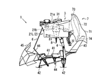
- FIG. 1 is a side view showing a vertical take-off and landing aircraft according to a first embodiment of the present invention. It is a block diagram from the front side of the power transmission mechanism in the vertical take-off and landing aircraft according to the first embodiment of the present invention. It is a partial rear view showing the main wing in the vertical take-off and landing aircraft according to the first embodiment of the present invention. It is a figure which shows the effect
- FIGS. 1A to 4B are views showing the vertical take-off and landing aircraft according to the first embodiment of the present invention.
- FIG. 1A is a side view
- FIG. 1B is a configuration diagram showing a power transmission mechanism
- FIG. 1C is a main wing.
- FIG. 1A is a side view
- FIG. 1B is a configuration diagram showing a power transmission mechanism
- FIG. 1C is a main wing.
- a vertical take-off and landing aircraft 1 includes a propulsion unit 2 that generates lift and thrust, a main frame 4 that supports a seat 41 and a grounding leg 42.
- the subframe 5 that supports the propelling device 2 and is pivotable in the front-rear direction with respect to the main frame 4, and the power that is supported by the main frame 4 or the subframe 5 and that supplies power to the propelling device 2 It has a supply means 3, a control stick 6 connected to the subframe 5, and a main wing 7 arranged in the propulsion device 2.
- the main wing 7 is retracted to a position where it does not interfere with the airflow of the propulsion device 2 at normal times. When the thrust is lost, it is configured to be movable to a position where lift is generated.
- the propulsion device 2 includes, for example, a ducted fan 21L disposed on the left side of the main shaft 4 (right side in FIG. 1B) and a ducted fan 21R disposed on the right side of the main frame 4 (left side in FIG. 1B).
- the ducted fans 21L and 21R are integrally connected by the subframe 5.
- Ducted fans 21L and 21R are generally configured by a substantially cylindrical duct 21a and a propeller 21b rotatably disposed in duct 21a, and a nose is located in front (upstream side) of the center of propeller 21b.
- a cone 21c is disposed, and a tail cone 21d is disposed behind (downstream) the center of the propeller 21b.
- the nose cone 21c has a function of smoothly guiding the gas sucked by the propeller 21b into the duct 21a, and the tail cone 21d has a function of rectifying the gas discharged from the duct 21a.
- the propeller 21b may have a pitch variable mechanism. By providing the pitch variable mechanism, the pitch of the left and right propellers 21b can be changed, and the maneuverability can be improved. Also, the propeller can be feathered to reduce air resistance during gliding.
- the power supply means 3 is, for example, a prime mover that supplies power to the ducted fans 21L and 21R by the power transmission mechanism shown in FIG. 1B.
- a prime mover that supplies power to the ducted fans 21L and 21R by the power transmission mechanism shown in FIG. 1B.
- an electric motor or a reciprocating engine may be used instead of the prime mover, or a supercharger may be installed.
- the power supply means 3 is fixed to the back surface of the main frame 4 and is supplied with fuel from an oil tank 31 disposed at the upper part of the fuselage, burns the fuel and outputs power, and an exhaust nozzle 32 disposed rearward. Exhaust gas from an oil tank 31 disposed at the upper part of the fuselage, burns the fuel and outputs power, and an exhaust nozzle 32 disposed rearward. Exhaust gas from
- the power transmission mechanism of the vertical take-off and landing aircraft 1 has power supply means 3, a sprocket 33 connected to the tip of the output shaft of the power supply means 3, and bevel gears 34a at both ends.
- a power transmission shaft 34 having a sprocket 34b in the middle, a roller chain spanned between the sprockets 33 and 34b, and a bearing 35 that rotatably supports the power transmission shaft 34;
- the output power is transmitted to the power transmission shaft 34 via the chain drive mechanism, and the rotation of the power transmission shaft 34 is transmitted to the drive shafts of the ducted fans 21L and 21R via the bevel gear 34a.
- the power transmission between the power supply means 3 and the power transmission shaft 34 is not limited to the chain drive mechanism, but may be a belt drive mechanism, a gear drive mechanism, a speed reducer or an increaser. A speed machine may be interposed. Further, when it is desired to individually control the rotational speed of each ducted fan 21L, 21R, the power supply means 3 may be individually connected to each ducted fan 21L, 21R.
- the bearing 35 that supports the power transmission shaft 34 is disposed on the main frame 4 to which the power supply means 3 is fixed, and is configured so that the positional relationship between the output shaft of the power supply means 3 and the power transmission shaft 34 does not fluctuate. Has been.
- the main frame 4 is a member that forms the skeleton of the fuselage and is a component that supports the propulsion device 2, the power supply means 3, the seat 41, the grounding leg 42, and the like.
- the main frame 4 preferably has a frame structure in order to reduce the weight of the airframe.
- a seat 41 for example, a front seat and a rear seat
- a plurality of ground legs 42 that constitute legs that contact the ground when landing, and the moment and balance of the fuselage are stabilized.
- the tail wing 43 to be moved, the footrest 44 for supporting the occupant's feet, and the like are arranged.
- a seat belt may be disposed on the seat 41, and a damper may be disposed on the grounding leg 42.
- a cowl 45 that is a rectifying means is connected in front of the seat 41.
- a part of the cowl 45 is made of a transparent member in order to secure a field of view, and a rearview mirror may be arranged on the side surface.
- the connecting portion 46 between the seat 41 and the cowl 45 may be used as a console box, or may be used as a control portion in which an operation switch and an operation lever of the power supply means 3 are arranged.
- the main body of the power supply means 3 is fixed to the back surface of the main frame 4, and an oil tank 31 is fixed to the upper part (ceiling part) of the main frame 4. Further, a plate member constituting a roof portion for avoiding rain may be disposed on the ceiling portion of the main frame 4.
- the subframe 5 is a component that connects the left and right ducted fans 21L and 21R.
- a control stick 6 extending in front of the seat 41 is connected to the subframe 5.
- the control stick 6 extends from the subframe 5 to the front of the seat 41 so that the subframe 5 is rotated in the front-rear direction with respect to the main frame 4 by rotating the control stick 6 in the front-rear direction. It is configured. Since the control stick 6 rotates the subframe 5 and the propulsion device 2, the control stick 6 may be connected to the outer peripheral surface of the propulsion device 2.
- the sub-frame 5 is rotatably connected to the main frame 4 by the frame connection part 51, as shown to FIG. 1B.
- the seat 41 and the power supply means 3 are fixed to the main frame 4 by such a frame structure, the seat 41 and the power supply means 3 have an integral structure and are configured not to move relative to each other.
- the propulsion device 2 ducted fans 21L and 21R
- the propulsion device 2 ducted fans 21L and 21R
- the propulsion device 2 is connected by rotatably connecting the subframe 5 to the main frame 4. Relative movement (rotation) with respect to the seat 41 and the power supply means 3 can be performed.
- the frame connecting portion 51 is configured such that the rotation axis of the power transmission shaft 34 and the rotation axis of the subframe 5 are arranged coaxially.
- the frame connecting portion 51 is connected to the lower surface of the main frame 4 and has a first cylindrical portion that can be inserted through the power transmission shaft 34 and the lower surface of the subframe 5 and is connected to the lower surface of the subframe 5.
- It has the rotation part 51b which has the 2nd cylinder part inserted by the inner side of one cylinder part, and the bearing (not shown) arrange
- the ducted fans 21L and 21R are rotated along the rotation axis of the power transmission shaft 34 while maintaining the connection state at the connecting portion (bevel gear 34a) between the power transmission shaft 34 and the ducted fans 21L and 21R. And the direction of the propulsion device 2 can be changed.
- the frame connecting portion 51 is not limited to the illustrated configuration as long as the main frame 4 and the sub frame 5 can be relatively moved (rotated).
- the sub-frame 5 having the propelling device 2 is configured to be rotatable with respect to the main frame 4 forming the skeleton of the airframe, and operates around the axis of the power transmission shaft 34 by operating the control stick 6.
- the propulsion device 2 ducted fans 21L, 21R
- the power supply means 3 described above may be arranged in the subframe 5 instead of the mainframe 4 although not shown. In this case, it is not necessary to arrange the rotating shaft of the power transmission shaft 34 and the rotation shaft of the subframe 5 on the same axis, and the power transmission mechanism can be simplified.
- the main wing 7 includes, for example, a pair of support panels 71 and 71 fixed to both side portions of the propelling device 2, and a main wing body 72 disposed between the support panels 71 and 71.
- the slat wing 73 is disposed in front of the main wing body 72
- the flap wing 74 is disposed in the rear of the main wing body 72.
- the slat wings 73 and the flap wings 74 are not essential components for the main wing body 72, and both may be omitted or only one of them may be arranged.
- the support panel 71 is made of, for example, a thin plate member having a streamline shape, and is fixed to the outer surface of the duct 21a of the ducted fans 21L and 21R. Note that the shape of the support panel 71 is not limited to the illustrated shape, and may be any other shape as long as aerodynamic resistance is taken into consideration. Although not shown, the support panel 71 may be fixed to the subframe 5.
- the main wing body 72 has, for example, a wing-shaped cross section as shown in FIG. 1A, and is arranged and fixed so as to be spanned between the support panels 71 and 71 as shown in FIG. 1C.
- the main wing body 72 has a surface area capable of generating lift necessary to glide the vertical take-off and landing aircraft 1 against gravity relative to the weight of the vertical take-off and landing aircraft 1 and the loaded weight (total weight of passengers and luggage). ing.
- the surface area of the main wing body 72 is appropriately changed according to conditions such as the weight of the vertical take-off and landing aircraft 1 and the maximum load weight. In order to increase the surface area of the main wing body 72, the lateral width of the main wing body 72 may be increased and the support panel 71 may be penetrated.
- the slat wing 73 is a kind of high lift device for increasing the lift of the aircraft.
- the slat wings 73 are arranged so as to form a certain gap with the front edge of the main wing body 72, for example. By disposing such slat wings 73, a part of the airflow passing through the lower surface side of the slat wings 73 can flow to the upper surface side of the main wing main body 72, and the separation of the airflow can be delayed.
- the slat wings 73 are not limited to fixed wings, and may be configured to be stored in the main wing body 72 during cruise flight.
- the flap wing 74 is also a kind of high lift device for increasing the lift of the aircraft.
- the flap blade 74 is disposed so as to form a certain gap with the rear edge of the main wing body 72.
- the flap wing 74 having such a configuration is called a slotted flap, and can make the camber of the main wing main body 72 longer, and a part of the airflow passing through the lower surface side of the main wing main body 72 flows to the upper surface side of the flap wing 74. Airflow separation can be delayed.
- the flap wings 74 are not limited to fixed wings, and may be configured such that the angle can be changed according to the flight state, or configured to be stored in the main wing body 72 during cruise flight. It may be.
- the main wing body 72 is disposed behind the propulsion device 2 (ducted fans 21L and 21R) with the propulsion device 2 (ducted fans 21L and 21R) facing vertically upward. It is configured as follows. That is, the main wing body 72 is disposed such that the chord direction is substantially parallel to the rotation axis of the ducted fans 21L and 21R. With this configuration, the main wing 7 does not interfere with the airflow passing through the ducted fans 21L and 21R.
- the main wing body 72 is disposed so as to have a certain gap between the main wing body 72 and the propulsion device 2 (ducted fans 21L and 21R). Specifically, the main wing body 72 has a certain clearance from the duct 21a of the ducted fans 21L and 21R and the power supply means 3 (exhaust nozzle 32, etc.). By forming such a gap, air current can flow between the propulsion device 2 (ducted fans 21L and 21R) and the main wing body 72 during gliding, and lift can be generated. This gap is appropriately set according to conditions such as the weight of the fuselage and the size of the main wing body 72.
- FIG. 2A shows the action during cruise flight
- FIG. 2B shows the action in the thrust loss state during cruise flight
- FIG. 3A shows the action during hovering
- FIG. 3B shows the action in the thrust loss state during hovering.
- the configuration other than the ducted fan 21L and the main wing 7 is omitted, and the support panel 71 is indicated by a one-dot chain line.
- the ducted fan 21L is steered forward with the power transmission shaft 34 as the center of rotation, and sucks air from the front and moves backward. Thrust is generated by blowing out.
- the main wing 7 is disposed above the ducted fan 21L, and the main wing main body 72 has an angle of attack of ⁇ with respect to the airflow A generated by the thrust of the ducted fan 21L.
- the airflow A passes through the gap between the main wing body 72 and the ducted fan 21L, and the main wing body 72 generates lift L (lift) and drag D (drag). Therefore, the aircraft body is lifted upward by the resultant force F, and the main wing 7 assists the flight of the vertical take-off and landing aircraft 1.
- the thruster 2 loses thrust.
- the main wing 7 that receives the airflow A and generates the lift L is provided, the main wing main body while the vertical take-off and landing aircraft 1 is flying by inertial force.
- the upward resultant force F that opposes the gravity of the vertical take-off and landing aircraft 1 can be generated by the airflow A that passes through the gap between the duct 72 and the ducted fan 21L.
- the vertical take-off and landing aircraft 1 can be safely and temporarily landed at a desired location.
- the vertical take-off and landing aircraft 1 can be turned by changing the weight of the occupant, and the traveling direction can be arbitrarily changed.
- the ducted fan 21L is driven in a state of being directed vertically upward with the power transmission shaft 34 as a rotation center, and sucks air from above to move downward. Thrust is generated by blowing out.
- the main wing 7 is arranged behind (in the back of) the ducted fan 21L, and is retracted to a position where it does not interfere with the airflow of the ducted fan 21L.
- the vertical take-off and landing aircraft 1 can be slid while avoiding the vertical take-off and landing aircraft 1 from falling vertically, as in the case of cruise flight.
- the vertical take-off and landing aircraft 1 can be safely landed at the place.
- the main wing 7 is arranged in the propulsion device 2 so that the propulsion device 2 can be rotated in conjunction with the propulsion device 2 at normal times (for example, during cruise flight or When hovering or the like) can be retracted to a position where it does not interfere with the airflow of the propulsion device 2, and when thrust is lost, it can be moved to a position where lift L is generated. Therefore, even if the propulsion device 2 loses thrust due to an engine trouble or the like, the main wing 7 can use the airflow A to generate the lift L and glide the airframe, thereby suppressing the vertical drop. be able to. Moreover, since it is only necessary to arrange the main wings 7 on the propulsion device 2, it is possible to suppress an increase in the size of the airframe.
- FIG. 4A is a side view showing the vertical take-off and landing aircraft according to the second embodiment of the present invention
- FIG. 4B is a side view showing the vertical take-off and landing aircraft according to the third embodiment.
- symbol is attached
- the propulsion device 2 may include control blades 8 that are configured by the ducted fans 21L and 21R and that control the flow direction of the airflow passing through the ducted fans 21L and 21R.
- the control wings 8 are arranged along the left and right directions of the ducted fans 21L and 21R. Specifically, a rotating shaft 81 is stretched between the duct 21a and the tail cone 21d of the ducted fans 21L and 21R, and the control blade 8 is fixed to the rotating shaft 81. Although not shown, one end of the rotation shaft 81 is rotatably supported by a bearing portion formed in the duct 21a, and the other end is connected to an actuator disposed in the tail cone 21d. Therefore, the control blade 8 can be rotated back and forth by rotating the rotation shaft 81.
- control wings 8 may be arranged on both the left and right sides of the tail cone 21d, or may be arranged only on either the inner side or the outer side. Further, the control blade 8 may be disposed so as to be exposed to the outside of the duct 21a, may be disposed so as to be accommodated in the duct 21a, or upstream of the propeller 21b of the ducted fans 21L and 21R. May be arranged.
- the control wings 8 are arranged in the front-rear direction of the ducted fans 21L and 21R. Specifically, a rotating shaft 81 is stretched along the left-right direction in the duct 21 a of the ducted fans 21 ⁇ / b> L and 21 ⁇ / b> R, and the control blade 8 is fixed to the rotating shaft 81.
- the rotating shaft 81 is rotatably supported at one end by a bearing portion formed in the duct 21a, and the other end is connected to an actuator disposed in the duct 21a. Therefore, the control blade 8 can be rotated back and forth by rotating the rotation shaft 81.
- control blades 8 may be disposed on both the front and rear sides of the tail cone 21d, or may be disposed only on either the front side or the rear side. Further, the control blade 8 may be disposed so as to be accommodated inside the duct 21a, may be disposed so as to be exposed to the outside of the duct 21a, or upstream of the propeller 21b of the ducted fans 21L and 21R. May be arranged.
- the flow of the airflow passing through the ducted fans 21L and 21R can be controlled by manipulating the rotation of the control blade 8, and thrust can be applied in a desired direction.
- the traveling direction of the vertical take-off and landing aircraft 1 is controlled by controlling the flow direction of the air flow.
- the vertical take-off and landing aircraft 1 can be steered toward a place suitable for emergency landing.
- a first aspect of the vertical take-off and landing aircraft includes a propulsion unit that generates lift and thrust, a main frame that supports a seat and a grounding leg, a propulsion unit that supports the propulsion unit and a longitudinal direction with respect to the main frame.
- a subframe that is pivotally disposed on the main frame, a power supply means that is supported by the main frame or the subframe and supplies power to the propulsion device, a control stick connected to the subframe, and the propulsion
- a main wing arranged on the sub-frame or the sub-frame, and the main wing is normally retracted to a position where it does not interfere with the air flow of the propellant and is movable to a position where lift is generated when thrust is lost It is supposed to be.
- the main wings are arranged in the propeller or subframe, so that the propeller can be rotated in conjunction with the propeller, for example, during cruise flight or hovering, the airflow of the propeller Can be retreated to a position where it does not interfere with, and when thrust is lost, it can be moved to a position where lift is generated.
- the main wing can use the airflow to generate lift and glide the aircraft, so that vertical fall can be suppressed. Become. Moreover, since it is only necessary to arrange the main wings on the propulsion unit or the subframe, the increase in size of the airframe can be suppressed.
- the main wing is configured by a pair of support panels fixed to both side portions of the propulsion device and a main wing body disposed between the support panels.
- the main wing body since both sides of the main wing body are respectively fixed to the pair of support panels, the main wing body has a high structural strength.
- the main wing is configured such that the main wing main body is arranged behind the propulsion unit with the propulsion unit facing vertically upward.
- the main wing can be prevented from interfering with the airflow passing through the propeller.
- the main wing body is disposed so as to have a certain gap between the main wing body and the propeller.
- the main wing includes at least one of a slat wing disposed in front of the main wing body and a flap wing disposed in the rear of the main wing body. It has a configuration.
- the separation of the airflow from the main wing body can be delayed.
- the propulsion unit is constituted by a ducted fan, and has control blades for controlling the direction of airflow passing through the ducted fan.
- the flow of the airflow passing through the propeller can be controlled, and the thrust can be generated in a desired direction.
Abstract
A vertical take-off and landing aircraft comprises: a propeller (2) which generates lift and thrust; a main frame (4) which supports a seat (41) and ground contact legs (42); a sub frame (5) which supports the propeller (2) and is rotatably disposed in a front-back direction with respect to the main frame (4); a power supply means (3) which is supported by the main frame (4) and supplies power to the propeller (2); a control stick (6) which is connected to the sub frame (5); and a main wing (7) which is disposed in the propeller (2), the main wing (7) being configured to usually retreat to a position that does not interfere with an air current generated by the propeller (2), and when the thrust is lost, be able to move to a position at which the lift is generated. Consequently, gliding becomes possible even when the thrust is lost while an increase in the size of the body thereof is suppressed.
Description
本発明は、垂直離着陸機に関し、特に、推力喪失時に安全に不時着可能な垂直離着陸機に関する。
The present invention relates to a vertical take-off and landing aircraft, and more particularly to a vertical take-off and landing aircraft that can safely and temporarily land when thrust is lost.
現在、滑走せずに揚力を発生させることができる垂直離着陸機として代表的なものは、ヘリコプターである。ヘリコプターは、機体に比して大きなローターを有し、かかるローターを回転させることによって揚力と推力を発生している。また、数少ない実例としては、ジェットエンジンの推力を偏向して垂直離着陸を行う固定翼機も存在している。
Currently, helicopters are a typical vertical take-off and landing aircraft that can generate lift without sliding. The helicopter has a rotor larger than the airframe, and generates lift and thrust by rotating the rotor. As a few examples, there are fixed wing aircraft that perform vertical takeoff and landing by deflecting the thrust of a jet engine.
ヘリコプターは、機体そのものが比較的大きいうえに、機体よりも大きなメインローターや機体後部にテールローターを有していることから、建築物や樹木等の障害物が存在している狭い空間において、離着陸や姿勢制御を行うと、メインローターやテールローターが障害物と接触してしまうため、離着陸のために広い空間が必要となる。
The helicopter is relatively large in size, and has a main rotor larger than the aircraft and a tail rotor at the rear of the aircraft. Therefore, helicopters take off and land in narrow spaces where obstacles such as buildings and trees exist. And attitude control, the main rotor and tail rotor come into contact with obstacles, so a large space is required for takeoff and landing.
一方、ジェットエンジンを使用した垂直離着陸可能な固定翼機の場合は、ジェット排気が高温であるとともに排気量が多いことから、離着陸時に石等の小さな物体がジェット排気により吹き飛ばされ、周囲の建築物等を傷つけてしまう。したがって、かかる固定翼機の場合も離着陸のために広い空間が必要となる。
On the other hand, in the case of a fixed-wing aircraft that uses a jet engine and can take off and land, jet exhaust is hot and the displacement is large, so small objects such as stones are blown away by jet exhaust during takeoff and landing, and surrounding buildings Etc. will be damaged. Therefore, even in the case of such fixed wing aircraft, a large space is required for takeoff and landing.
そこで、狭い空間であっても安全に離着陸することができる垂直離着陸機(VTOL:Vertical Take-off and Landing)が既に提案されている(例えば、特許文献1、特許文献2等参照)。特許文献1及び特許文献2に記載された垂直離着陸機は、円筒形のダクトやナセルの中にプロペラ状のファンが配置されたダクテッドファンを備えている。
Therefore, a vertical take-off and landing aircraft (VTOL: Vertical Take-off and Landing) that can safely take off and land even in a narrow space has already been proposed (see, for example, Patent Document 1 and Patent Document 2). The vertical take-off and landing aircraft described in Patent Document 1 and Patent Document 2 includes a ducted fan in which a propeller-shaped fan is disposed in a cylindrical duct or nacelle.
しかしながら、特許文献1に記載された垂直離着陸機は、推力発生手段がダクテッドファンだけであることから、ファンが停止して推力を喪失した場合には機体は垂直落下してしまうという問題がある。また、緊急事態に備えて、パラシュートを配備しておくことも考えられるが、パラシュートの開傘には一定の時間を要し、十分な高度を有していなければならず、乗員が曝露した状態で操縦する垂直離着陸機への適応が難しいという問題もあった。
However, since the vertical take-off and landing aircraft described in Patent Document 1 has only a ducted fan as the thrust generating means, there is a problem that the aircraft falls vertically when the fan stops and loses thrust. It is also possible to deploy a parachute in case of an emergency, but it takes a certain amount of time to open the parachute, it must have sufficient altitude, and the passenger is exposed. There was also a problem that it was difficult to adapt to the vertical take-off and landing aircraft operated by the aircraft.
また、特許文献2に記載された垂直離着陸機は、航空機の機体にダクテッドファンを配置したものであり、航空機と同様の主翼を有していることから、ファンが停止して推力を喪失した場合であったとしても主翼により滑空することができるので、不時着を試みることができる。しかしながら、かかる垂直離着陸機は、航空機の機体をベースにしていることから、機体全体が大型化してしまい、離着陸に一定の広い空間を必要とし、垂直離着陸機の利点を減殺させてしまうという問題があった。
In addition, the vertical take-off and landing aircraft described in Patent Document 2 has a ducted fan arranged on the aircraft body, and has a main wing similar to an aircraft, so that the fan stops and loses thrust. Even if there is, you can glide with the main wing, so you can try to land on time. However, since such a vertical take-off and landing aircraft is based on the aircraft body, the entire aircraft becomes larger, requiring a certain wide space for take-off and landing, and reducing the advantages of the vertical take-off and landing aircraft. there were.
本発明は上述した問題点に鑑み創案されたものであり、機体の大型化を抑制しつつ、推力喪失時であったとしても滑空することができる、垂直離着陸機を提供することを目的とする。
The present invention was devised in view of the above-described problems, and an object thereof is to provide a vertical take-off and landing aircraft that can glide even when thrust is lost while suppressing an increase in size of the aircraft. .
本発明は、垂直離着陸機であって、揚力及び推力を発生させる推進器と、座席及び接地脚を支持するメインフレームと、前記推進器を支持するとともに前記メインフレームに対して前後方向に回動可能に配置されたサブフレームと、前記メインフレーム又は前記サブフレームに支持されるとともに前記推進器に動力を供給する動力供給手段と、前記サブフレームに接続された操縦桿と、前記推進器又は前記サブフレームに配置された主翼と、を有し、前記主翼は、通常時は前記推進器の気流と干渉しない位置に退避し、推力喪失時は揚力を発生させる位置に移動可能に構成されている。
The present invention is a vertical take-off and landing aircraft, a propulsion device that generates lift and thrust, a main frame that supports a seat and a ground leg, and supports the propulsion device and rotates in the front-rear direction with respect to the main frame A subframe arranged in a possible manner, a power supply means which is supported by the main frame or the subframe and supplies power to the propeller, a control stick connected to the subframe, the propeller or the A main wing disposed in a sub-frame, and the main wing is normally retracted to a position where it does not interfere with the air flow of the thruster, and is configured to be movable to a position where lift is generated when thrust is lost. .
本発明の垂直離着陸機によれば、推進器又はサブフレームに主翼を配置したことにより、推進器と連動して回動させることができ、通常時(例えば、巡航飛行時やホバリング時等)は推進器の気流と干渉しない位置に退避させることができ、推力喪失時は揚力を発生させる位置に移動させることができる。
According to the vertical take-off and landing aircraft of the present invention, the main wing is arranged in the propeller or subframe, so that it can be rotated in conjunction with the propeller, and during normal times (for example, during cruise flight or hovering) It can be retreated to a position where it does not interfere with the airflow of the propelling device, and can be moved to a position where lift is generated when thrust is lost.
上述した本発明の垂直離着陸機によれば、推進器がエンジントラブル等により推力を喪失した場合であったとしても、主翼により気流を利用して揚力を発生させて機体を滑空させることができるので、垂直落下を抑制することができる。また、推進器又はサブフレームに主翼を配置するだけでよいことから、機体の大型化を抑制することもできる。
According to the vertical take-off and landing aircraft of the present invention described above, even if the propulsion device loses thrust due to engine trouble or the like, the main wing can use the airflow to generate lift and glide the aircraft. , Vertical drop can be suppressed. Moreover, since it is only necessary to arrange the main wings on the propulsion unit or the subframe, it is possible to suppress an increase in size of the airframe.
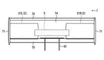
以下、本発明の実施形態について図1A~図4Bを用いて説明する。ここで、図1A~図1Cは、本発明の第一実施形態に係る垂直離着陸機を示す図であり、図1Aは側面図、図1Bは動力伝達機構を示す構成図、図1Cは主翼を示す部分背面図、である。
Hereinafter, embodiments of the present invention will be described with reference to FIGS. 1A to 4B. 1A to 1C are views showing the vertical take-off and landing aircraft according to the first embodiment of the present invention. FIG. 1A is a side view, FIG. 1B is a configuration diagram showing a power transmission mechanism, and FIG. 1C is a main wing. FIG.
本発明の第一実施形態に係る垂直離着陸機1は、図1A~図1Cに示したように、揚力及び推力を発生させる推進器2と、座席41及び接地脚42を支持するメインフレーム4と、推進器2を支持するとともにメインフレーム4に対して前後方向に回動可能に配置されたサブフレーム5と、メインフレーム4又はサブフレーム5に支持されるとともに推進器2に動力を供給する動力供給手段3と、サブフレーム5に接続された操縦桿6と、推進器2に配置された主翼7と、を有し、主翼7は、通常時は推進器2の気流と干渉しない位置に退避し、推力喪失時は揚力を発生させる位置に移動可能に構成されている。
As shown in FIGS. 1A to 1C, a vertical take-off and landing aircraft 1 according to a first embodiment of the present invention includes a propulsion unit 2 that generates lift and thrust, a main frame 4 that supports a seat 41 and a grounding leg 42. The subframe 5 that supports the propelling device 2 and is pivotable in the front-rear direction with respect to the main frame 4, and the power that is supported by the main frame 4 or the subframe 5 and that supplies power to the propelling device 2 It has a supply means 3, a control stick 6 connected to the subframe 5, and a main wing 7 arranged in the propulsion device 2. The main wing 7 is retracted to a position where it does not interfere with the airflow of the propulsion device 2 at normal times. When the thrust is lost, it is configured to be movable to a position where lift is generated.
前記推進器2は、例えば、メインフレーム4の機軸左側(図1Bの右側)に配置されるダクテッドファン21Lと、メインフレーム4の機軸右側(図1Bの左側)に配置されるダクテッドファン21Rと、を有し、これらのダクテッドファン21L,21Rはサブフレーム5により一体に連結されている。
The propulsion device 2 includes, for example, a ducted fan 21L disposed on the left side of the main shaft 4 (right side in FIG. 1B) and a ducted fan 21R disposed on the right side of the main frame 4 (left side in FIG. 1B). The ducted fans 21L and 21R are integrally connected by the subframe 5.
ダクテッドファン21L,21Rは、一般に、略円筒形状のダクト21aと、ダクト21a内に回転可能に配置されたプロペラ21bと、により構成されており、プロペラ21bの中心部の前方(上流側)にはノーズコーン21cが配置され、プロペラ21bの中心部の後方(下流側)にはテールコーン21dが配置されている。ノーズコーン21cは、プロペラ21bにより吸い込まれる気体をダクト21a内に滑らかに案内する機能を有し、テールコーン21dはダクト21aから排出される気体を整流する機能を有している。
Ducted fans 21L and 21R are generally configured by a substantially cylindrical duct 21a and a propeller 21b rotatably disposed in duct 21a, and a nose is located in front (upstream side) of the center of propeller 21b. A cone 21c is disposed, and a tail cone 21d is disposed behind (downstream) the center of the propeller 21b. The nose cone 21c has a function of smoothly guiding the gas sucked by the propeller 21b into the duct 21a, and the tail cone 21d has a function of rectifying the gas discharged from the duct 21a.
また、図示しないが、プロペラ21bはピッチ可変機構を有していてもよい。ピッチ可変機構を設けることにより、左右のプロペラ21bのピッチを変更することができ、操縦性を向上させることができる。また、滑空時に空気抵抗を減少させるためにプロペラをフェザリングさせることもできる。
Although not shown, the propeller 21b may have a pitch variable mechanism. By providing the pitch variable mechanism, the pitch of the left and right propellers 21b can be changed, and the maneuverability can be improved. Also, the propeller can be feathered to reduce air resistance during gliding.
前記動力供給手段3は、例えば、図1Bに示した動力伝達機構により、ダクテッドファン21L,21Rに動力を供給する原動機である。動力源としては、原動機に替えて、電動モータやレシプロエンジン等を使用してもよいし、過給機を設置するようにしてもよい。動力供給手段3は、メインフレーム4の背面に固定されており、機体上部に配置されたオイルタンク31から燃料が供給され、燃料を燃焼させて動力を出力し、後方に配置された排気ノズル32から排気ガスを排出する。
The power supply means 3 is, for example, a prime mover that supplies power to the ducted fans 21L and 21R by the power transmission mechanism shown in FIG. 1B. As the power source, an electric motor or a reciprocating engine may be used instead of the prime mover, or a supercharger may be installed. The power supply means 3 is fixed to the back surface of the main frame 4 and is supplied with fuel from an oil tank 31 disposed at the upper part of the fuselage, burns the fuel and outputs power, and an exhaust nozzle 32 disposed rearward. Exhaust gas from
図1Bに示したように、垂直離着陸機1の動力伝達機構は、動力供給手段3と、動力供給手段3の出力軸の先端に接続されたスプロケット33と、両端部に傘歯車34aを有するとともに中間部にスプロケット34bを有する動力伝達シャフト34と、スプロケット33,34b間に掛け渡されたローラチェーンと、動力伝達シャフト34を回転可能に支持する軸受35と、を有し、動力供給手段3により出力される動力は、チェーン駆動機構を介して動力伝達シャフト34に伝達され、動力伝達シャフト34の回転は傘歯車34aを介してダクテッドファン21L,21Rの駆動軸に伝達される。
As shown in FIG. 1B, the power transmission mechanism of the vertical take-off and landing aircraft 1 has power supply means 3, a sprocket 33 connected to the tip of the output shaft of the power supply means 3, and bevel gears 34a at both ends. A power transmission shaft 34 having a sprocket 34b in the middle, a roller chain spanned between the sprockets 33 and 34b, and a bearing 35 that rotatably supports the power transmission shaft 34; The output power is transmitted to the power transmission shaft 34 via the chain drive mechanism, and the rotation of the power transmission shaft 34 is transmitted to the drive shafts of the ducted fans 21L and 21R via the bevel gear 34a.
動力供給手段3と動力伝達シャフト34との動力伝達は、チェーン駆動機構に限定されるものではなく、ベルト駆動機構であってもよいし、歯車駆動機構であってもよいし、減速機や増速機を介在させるようにしてもよい。また、各ダクテッドファン21L,21Rの回転数を個別に制御したい場合には、各ダクテッドファン21L,21Rに個別に動力供給手段3を接続するようにしてもよい。動力伝達シャフト34を支持する軸受35は、動力供給手段3が固定されるメインフレーム4に配置されており、動力供給手段3の出力軸と動力伝達シャフト34との位置関係が変動しないように構成されている。
The power transmission between the power supply means 3 and the power transmission shaft 34 is not limited to the chain drive mechanism, but may be a belt drive mechanism, a gear drive mechanism, a speed reducer or an increaser. A speed machine may be interposed. Further, when it is desired to individually control the rotational speed of each ducted fan 21L, 21R, the power supply means 3 may be individually connected to each ducted fan 21L, 21R. The bearing 35 that supports the power transmission shaft 34 is disposed on the main frame 4 to which the power supply means 3 is fixed, and is configured so that the positional relationship between the output shaft of the power supply means 3 and the power transmission shaft 34 does not fluctuate. Has been.
前記メインフレーム4は、機体の骨格をなす部材であって、推進器2、動力供給手段3、座席41、接地脚42等を支持する構成部品である。メインフレーム4は、機体の軽量化を図るためにフレーム構造であることが好ましい。メインフレーム4の下部には、乗員が着座する座席41(例えば、前部座席及び後部座席)、着陸時に地面等に接地する脚部を構成する複数の接地脚42、機体のモーメントやバランスを安定させる尾翼43、乗員の足を支持するフットレスト44等が配置されている。座席41にはシートベルトを配置してもよいし、接地脚42にはダンパーを配置してもよい。
The main frame 4 is a member that forms the skeleton of the fuselage and is a component that supports the propulsion device 2, the power supply means 3, the seat 41, the grounding leg 42, and the like. The main frame 4 preferably has a frame structure in order to reduce the weight of the airframe. At the lower part of the main frame 4, a seat 41 (for example, a front seat and a rear seat) on which an occupant sits, a plurality of ground legs 42 that constitute legs that contact the ground when landing, and the moment and balance of the fuselage are stabilized. The tail wing 43 to be moved, the footrest 44 for supporting the occupant's feet, and the like are arranged. A seat belt may be disposed on the seat 41, and a damper may be disposed on the grounding leg 42.
また、座席41の前方には整流手段であるカウル45が接続されている。カウル45の一部は、視界を確保するために透明の部材により構成されており、側面部にはバックミラーが配置されていてもよい。また、座席41とカウル45との接続部46は、コンソールボックスとして使用するようにしてもよいし、動力供給手段3の操作スイッチや操作レバーを配置する制御部として使用するようにしてもよい。
Further, a cowl 45 that is a rectifying means is connected in front of the seat 41. A part of the cowl 45 is made of a transparent member in order to secure a field of view, and a rearview mirror may be arranged on the side surface. Further, the connecting portion 46 between the seat 41 and the cowl 45 may be used as a console box, or may be used as a control portion in which an operation switch and an operation lever of the power supply means 3 are arranged.
また、メインフレーム4の背面には動力供給手段3の本体が固定されており、メインフレーム4の上部(天井部)にはオイルタンク31が固定されている。また、メインフレーム4の天井部には、雨避け用のルーフ部を構成する板部材を配置するようにしてもよい。
The main body of the power supply means 3 is fixed to the back surface of the main frame 4, and an oil tank 31 is fixed to the upper part (ceiling part) of the main frame 4. Further, a plate member constituting a roof portion for avoiding rain may be disposed on the ceiling portion of the main frame 4.
前記サブフレーム5は、左右のダクテッドファン21L,21Rを接続する構成部品である。また、サブフレーム5には、座席41の前方に延設された操縦桿6が接続されている。操縦桿6は、サブフレーム5から座席41の前方まで延設されており、操縦桿6を前後方向に回動させることによってサブフレーム5をメインフレーム4に対して前後方向に回動させるように構成されている。操縦桿6は、サブフレーム5及び推進器2を回動させるものであるため、推進器2の外周面に操縦桿6が接続されていてもよい。そして、サブフレーム5は、図1Bに示したように、フレーム連結部51によりメインフレーム4に回動可能に接続される。
The subframe 5 is a component that connects the left and right ducted fans 21L and 21R. In addition, a control stick 6 extending in front of the seat 41 is connected to the subframe 5. The control stick 6 extends from the subframe 5 to the front of the seat 41 so that the subframe 5 is rotated in the front-rear direction with respect to the main frame 4 by rotating the control stick 6 in the front-rear direction. It is configured. Since the control stick 6 rotates the subframe 5 and the propulsion device 2, the control stick 6 may be connected to the outer peripheral surface of the propulsion device 2. And the sub-frame 5 is rotatably connected to the main frame 4 by the frame connection part 51, as shown to FIG. 1B.
かかるフレーム構造により、座席41や動力供給手段3はメインフレーム4に固定されていることから、一体構造をなしており、相対移動しないように構成されている。一方、推進器2(ダクテッドファン21L,21R)はサブフレーム5に固定されていることから、サブフレーム5をメインフレーム4に回動可能に接続することにより、推進器2(ダクテッドファン21L,21R)を座席41や動力供給手段3に対して相対移動(回動)させることができる。
Since the seat 41 and the power supply means 3 are fixed to the main frame 4 by such a frame structure, the seat 41 and the power supply means 3 have an integral structure and are configured not to move relative to each other. On the other hand, since the propulsion device 2 (ducted fans 21L and 21R) is fixed to the subframe 5, the propulsion device 2 (ducted fans 21L and 21R) is connected by rotatably connecting the subframe 5 to the main frame 4. Relative movement (rotation) with respect to the seat 41 and the power supply means 3 can be performed.
フレーム連結部51は、動力伝達シャフト34の回転軸とサブフレーム5の回動軸とが同軸上に配置されるように構成されている。また、フレーム連結部51は、例えば、メインフレーム4の下面に接続されるとともに動力伝達シャフト34を挿通可能な第一筒部を有する本体部51aと、サブフレーム5の下面に接続されるとともに第一筒部の内側に挿嵌される第二筒部を有する回動部51bと、第一筒部と第二筒部との間に配置された軸受(図示せず)と、を有する。
The frame connecting portion 51 is configured such that the rotation axis of the power transmission shaft 34 and the rotation axis of the subframe 5 are arranged coaxially. In addition, the frame connecting portion 51 is connected to the lower surface of the main frame 4 and has a first cylindrical portion that can be inserted through the power transmission shaft 34 and the lower surface of the subframe 5 and is connected to the lower surface of the subframe 5. It has the rotation part 51b which has the 2nd cylinder part inserted by the inner side of one cylinder part, and the bearing (not shown) arrange | positioned between the 1st cylinder part and the 2nd cylinder part.
かかる構成によれば、動力伝達シャフト34とダクテッドファン21L,21Rとの連結部(傘歯車34a)における接続状態を維持したまま、ダクテッドファン21L,21Rを動力伝達シャフト34の回転軸に沿って回動させることができ、推進器2の向きを変更することができる。なお、フレーム連結部51は、メインフレーム4とサブフレーム5とを相対移動(回動)させることができればよく、図示した構成に限定されるものではない。
According to such a configuration, the ducted fans 21L and 21R are rotated along the rotation axis of the power transmission shaft 34 while maintaining the connection state at the connecting portion (bevel gear 34a) between the power transmission shaft 34 and the ducted fans 21L and 21R. And the direction of the propulsion device 2 can be changed. Note that the frame connecting portion 51 is not limited to the illustrated configuration as long as the main frame 4 and the sub frame 5 can be relatively moved (rotated).
上述したように、推進器2を有するサブフレーム5は、機体の骨格を形成するメインフレーム4に対して回動可能に構成されており、操縦桿6を操作して動力伝達シャフト34の軸回りに回動させることによって、推進器2(ダクテッドファン21L,21R)を前後方向に回動(傾斜)させることができ、機体の進行方向等を制御することができる。なお、上述した動力供給手段3は、図示しないが、メインフレーム4ではなくサブフレーム5に配置されていてもよい。この場合、動力伝達シャフト34の回転軸とサブフレーム5の回動軸とは、同軸上に配置する必要はなく、動力伝達機構の簡素化を図ることができる。
As described above, the sub-frame 5 having the propelling device 2 is configured to be rotatable with respect to the main frame 4 forming the skeleton of the airframe, and operates around the axis of the power transmission shaft 34 by operating the control stick 6. , The propulsion device 2 (ducted fans 21L, 21R) can be rotated (tilted) in the front-rear direction, and the traveling direction of the aircraft can be controlled. The power supply means 3 described above may be arranged in the subframe 5 instead of the mainframe 4 although not shown. In this case, it is not necessary to arrange the rotating shaft of the power transmission shaft 34 and the rotation shaft of the subframe 5 on the same axis, and the power transmission mechanism can be simplified.
主翼7は、図1A及び図1Cに示したように、例えば、推進器2の両側部に固定される一対の支持パネル71,71と、支持パネル71,71間に配置される主翼本体72と、主翼本体72の前方に配置されたスラット翼73と、主翼本体72の後方に配置されたフラップ翼74と、により構成される。なお、スラット翼73及びフラップ翼74は、主翼本体72に対して必須の構成要素ではなく、両方とも省略してもよいし、いずれか一方のみを配置するようにしてもよい。
As shown in FIGS. 1A and 1C, the main wing 7 includes, for example, a pair of support panels 71 and 71 fixed to both side portions of the propelling device 2, and a main wing body 72 disposed between the support panels 71 and 71. The slat wing 73 is disposed in front of the main wing body 72, and the flap wing 74 is disposed in the rear of the main wing body 72. The slat wings 73 and the flap wings 74 are not essential components for the main wing body 72, and both may be omitted or only one of them may be arranged.
支持パネル71は、例えば、流線形を有する薄板部材により構成されており、ダクテッドファン21L,21Rのダクト21aの外面に固定される。なお、支持パネル71の形状は図示したものに限定されず、空力抵抗を考慮した形状であれば他の形状であってもよい。また、図示しないが、支持パネル71は、サブフレーム5に固定されていてもよい。
The support panel 71 is made of, for example, a thin plate member having a streamline shape, and is fixed to the outer surface of the duct 21a of the ducted fans 21L and 21R. Note that the shape of the support panel 71 is not limited to the illustrated shape, and may be any other shape as long as aerodynamic resistance is taken into consideration. Although not shown, the support panel 71 may be fixed to the subframe 5.
主翼本体72は、例えば、図1Aに示したように、翼形状断面を有しており、図1Cに示したように、支持パネル71,71間に掛け渡されるように配置され固定される。主翼本体72は、垂直離着陸機1の機体重量及び積載重量(乗員及び荷物の総重量)に対する重力に対して垂直離着陸機1を滑空させるために必要な揚力を発生させることができる表面積を有している。主翼本体72の表面積は、垂直離着陸機1の機体重量や最大積載重量等の条件によって適宜変更される。なお、主翼本体72の表面積をより大きくしたい場合には、主翼本体72の横幅を長くして、支持パネル71を貫通させて配置するようにしてもよい。
The main wing body 72 has, for example, a wing-shaped cross section as shown in FIG. 1A, and is arranged and fixed so as to be spanned between the support panels 71 and 71 as shown in FIG. 1C. The main wing body 72 has a surface area capable of generating lift necessary to glide the vertical take-off and landing aircraft 1 against gravity relative to the weight of the vertical take-off and landing aircraft 1 and the loaded weight (total weight of passengers and luggage). ing. The surface area of the main wing body 72 is appropriately changed according to conditions such as the weight of the vertical take-off and landing aircraft 1 and the maximum load weight. In order to increase the surface area of the main wing body 72, the lateral width of the main wing body 72 may be increased and the support panel 71 may be penetrated.
スラット翼73は機体の揚力を増大させるための高揚力装置の一種である。スラット翼73は、例えば、主翼本体72の前縁との間に一定の隙間を形成するように配置される。かかるスラット翼73を配置することにより、スラット翼73の下面側を通る気流の一部を主翼本体72の上面側に流して、気流の剥離を遅らせることができる。なお、スラット翼73は、固定翼に限定されるものではなく、巡航飛行時は主翼本体72に格納できるように構成されていてもよい。
The slat wing 73 is a kind of high lift device for increasing the lift of the aircraft. The slat wings 73 are arranged so as to form a certain gap with the front edge of the main wing body 72, for example. By disposing such slat wings 73, a part of the airflow passing through the lower surface side of the slat wings 73 can flow to the upper surface side of the main wing main body 72, and the separation of the airflow can be delayed. The slat wings 73 are not limited to fixed wings, and may be configured to be stored in the main wing body 72 during cruise flight.
フラップ翼74も機体の揚力を増大させるための高揚力装置の一種である。フラップ翼74は、例えば、主翼本体72の後縁との間に一定の隙間を形成するように配置される。かかる構成のフラップ翼74は、スロッテドフラップと称され、主翼本体72のキャンバーを長くすることができるとともに、主翼本体72の下面側を通る気流の一部をフラップ翼74の上面側に流して、気流の剥離を遅らせることができる。なお、フラップ翼74は、固定翼に限定されるものではなく、飛行状態に応じて角度を変更できるように構成されていてもよいし、巡航飛行時は主翼本体72に格納できるように構成されていてもよい。
The flap wing 74 is also a kind of high lift device for increasing the lift of the aircraft. For example, the flap blade 74 is disposed so as to form a certain gap with the rear edge of the main wing body 72. The flap wing 74 having such a configuration is called a slotted flap, and can make the camber of the main wing main body 72 longer, and a part of the airflow passing through the lower surface side of the main wing main body 72 flows to the upper surface side of the flap wing 74. Airflow separation can be delayed. Note that the flap wings 74 are not limited to fixed wings, and may be configured such that the angle can be changed according to the flight state, or configured to be stored in the main wing body 72 during cruise flight. It may be.
また、主翼7は、図1Aに示したように、推進器2(ダクテッドファン21L,21R)が鉛直上方を向いた状態で主翼本体72が推進器2(ダクテッドファン21L,21R)の後方に配置されるように構成されている。すなわち、主翼本体72は、翼弦方向がダクテッドファン21L,21Rの回転軸と略平行となるように配置される。かかる構成により、ダクテッドファン21L,21Rを通過する気流に対して主翼7が干渉することはない。
In the main wing 7, as shown in FIG. 1A, the main wing body 72 is disposed behind the propulsion device 2 (ducted fans 21L and 21R) with the propulsion device 2 (ducted fans 21L and 21R) facing vertically upward. It is configured as follows. That is, the main wing body 72 is disposed such that the chord direction is substantially parallel to the rotation axis of the ducted fans 21L and 21R. With this configuration, the main wing 7 does not interfere with the airflow passing through the ducted fans 21L and 21R.
また、主翼本体72は、推進器2(ダクテッドファン21L,21R)との間に一定の隙間を有するように配置されている。具体的には、主翼本体72は、ダクテッドファン21L,21Rのダクト21aや動力供給手段3(排気ノズル32等)と一定の隙間を有する。かかる隙間を形成することにより、滑空時に気流を推進器2(ダクテッドファン21L,21R)と主翼本体72との間に流すことができ、揚力を発生させることができる。この隙間は、機体重量、主翼本体72の大きさ等の条件によって適宜設定される。
Further, the main wing body 72 is disposed so as to have a certain gap between the main wing body 72 and the propulsion device 2 (ducted fans 21L and 21R). Specifically, the main wing body 72 has a certain clearance from the duct 21a of the ducted fans 21L and 21R and the power supply means 3 (exhaust nozzle 32, etc.). By forming such a gap, air current can flow between the propulsion device 2 (ducted fans 21L and 21R) and the main wing body 72 during gliding, and lift can be generated. This gap is appropriately set according to conditions such as the weight of the fuselage and the size of the main wing body 72.
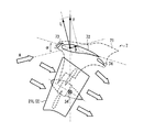
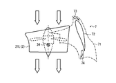
次に、上述した主翼7の作用について、図2A~図3Bを参照しつつ説明する。ここで、図2Aは、巡航飛行時における作用を示しており、図2Bは、巡航飛行時における推力喪失状態の作用を示している。図3Aは、ホバリング時における作用を示しており、図3Bは、ホバリング時における推力喪失状態の作用を示している。なお、各図において、説明の便宜上、ダクテッドファン21Lと主翼7以外の構成を省略するとともに、支持パネル71を一点鎖線で図示している。
Next, the operation of the main wing 7 will be described with reference to FIGS. 2A to 3B. Here, FIG. 2A shows the action during cruise flight, and FIG. 2B shows the action in the thrust loss state during cruise flight. FIG. 3A shows the action during hovering, and FIG. 3B shows the action in the thrust loss state during hovering. In each figure, for convenience of explanation, the configuration other than the ducted fan 21L and the main wing 7 is omitted, and the support panel 71 is indicated by a one-dot chain line.
図2Aに示したように、垂直離着陸機1の巡航飛行時には、ダクテッドファン21Lは、動力伝達シャフト34を回動中心にして前方に傾斜した状態に操縦されており、前方から空気を吸い込んで後方に噴き出すことによって推力を発生させている。このとき、主翼7は、ダクテッドファン21Lの上方に配置されており、主翼本体72は、ダクテッドファン21Lの推力により発生した気流Aに対してαの迎角を有している状態になっている。
As shown in FIG. 2A, during the cruise flight of the vertical take-off and landing aircraft 1, the ducted fan 21L is steered forward with the power transmission shaft 34 as the center of rotation, and sucks air from the front and moves backward. Thrust is generated by blowing out. At this time, the main wing 7 is disposed above the ducted fan 21L, and the main wing main body 72 has an angle of attack of α with respect to the airflow A generated by the thrust of the ducted fan 21L.
かかる巡航飛行状態において、気流Aは、主翼本体72とダクテッドファン21Lとの隙間を通過し、主翼本体72には揚力L(リフト)及び抗力D(ドラッグ)が生じる。したがって、その合力Fによって機体は上方に持ち上げられることとなり、主翼7は垂直離着陸機1の飛行を補助することとなる。
In such a cruise flight state, the airflow A passes through the gap between the main wing body 72 and the ducted fan 21L, and the main wing body 72 generates lift L (lift) and drag D (drag). Therefore, the aircraft body is lifted upward by the resultant force F, and the main wing 7 assists the flight of the vertical take-off and landing aircraft 1.
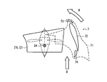
そして、巡航飛行状態において、エンジントラブル等によりダクテッドファン21Lの回転が著しく低下又は停止した場合には、推進器2が推力を喪失することとなる。しかしながら、本実施形態では、図2Bに示したように、気流Aを受けて揚力Lを発生させる主翼7を備えていることから、慣性力によって垂直離着陸機1が飛行している間、主翼本体72とダクテッドファン21Lとの隙間を通過する気流Aによって、垂直離着陸機1の重力に対抗する上向きの合力Fを発生させることができる。
In the cruise flight state, if the rotation of the ducted fan 21L is significantly reduced or stopped due to engine trouble or the like, the thruster 2 loses thrust. However, in the present embodiment, as shown in FIG. 2B, since the main wing 7 that receives the airflow A and generates the lift L is provided, the main wing main body while the vertical take-off and landing aircraft 1 is flying by inertial force. The upward resultant force F that opposes the gravity of the vertical take-off and landing aircraft 1 can be generated by the airflow A that passes through the gap between the duct 72 and the ducted fan 21L.
したがって、垂直離着陸機1の垂直落下を回避しつつ、垂直離着陸機1をそのまま滑空させることができる。また、操縦桿6を操作することによって、所望の場所に垂直離着陸機1を安全に不時着させることができる。なお、本実施形態に係る垂直離着陸機1では、乗員の体重移動によって、垂直離着陸機1を旋回させることができ、進行方向を任意に変更することができる。
Therefore, it is possible to glide the vertical take-off and landing aircraft 1 as it is while avoiding the vertical take-off and landing aircraft 1 from falling vertically. Further, by operating the control stick 6, the vertical take-off and landing aircraft 1 can be safely and temporarily landed at a desired location. In the vertical take-off and landing aircraft 1 according to the present embodiment, the vertical take-off and landing aircraft 1 can be turned by changing the weight of the occupant, and the traveling direction can be arbitrarily changed.
図3Aに示したように、垂直離着陸機1のホバリング時には、ダクテッドファン21Lは、動力伝達シャフト34を回動中心にして鉛直上方に向いた状態に操縦されており、上方から空気を吸い込んで下方に噴き出すことによって推力を発生させている。このとき、主翼7は、ダクテッドファン21Lの後方(背面)に配置されており、ダクテッドファン21Lの気流と干渉しない位置に退避している。
As shown in FIG. 3A, when the vertical take-off and landing aircraft 1 is hovered, the ducted fan 21L is driven in a state of being directed vertically upward with the power transmission shaft 34 as a rotation center, and sucks air from above to move downward. Thrust is generated by blowing out. At this time, the main wing 7 is arranged behind (in the back of) the ducted fan 21L, and is retracted to a position where it does not interfere with the airflow of the ducted fan 21L.
そして、ホバリング状態において、エンジントラブル等によりダクテッドファン21Lの回転が著しく低下又は停止した場合には、推進器2が推力を喪失することとなる。このとき、垂直離着陸機1は垂直落下しようとするが、図3Bに示したように、主翼本体72とダクテッドファン21Lとの隙間に下流側から気流Bが通過することとなる。その結果、主翼7は、気流Bの風圧を受けて、前方に回転しようとする回転力Rを生じさせる。主翼7が前方に回転すると、主翼本体72とダクテッドファン21Lとの隙間には上流側から気流Aが通過することとなり、最終的に、図2Bに示した状態と同じ姿勢へと移行する。
In the hovering state, when the rotation of the ducted fan 21L is significantly reduced or stopped due to an engine trouble or the like, the thruster 2 loses thrust. At this time, the vertical take-off and landing aircraft 1 tries to fall vertically, but as shown in FIG. 3B, the airflow B passes through the gap between the main wing body 72 and the ducted fan 21L from the downstream side. As a result, the main wing 7 receives the wind pressure of the airflow B and generates a rotational force R that tends to rotate forward. When the main wing 7 rotates forward, the airflow A passes through the gap between the main wing main body 72 and the ducted fan 21L from the upstream side, and finally shifts to the same posture as shown in FIG. 2B.
したがって、ホバリング時においても、巡航飛行時の場合と同様に、垂直離着陸機1の垂直落下を回避しつつ、垂直離着陸機1を滑空させることができ、操縦桿6を操作することによって、所望の場所に垂直離着陸機1を安全に不時着させることができる。
Accordingly, even during hovering, the vertical take-off and landing aircraft 1 can be slid while avoiding the vertical take-off and landing aircraft 1 from falling vertically, as in the case of cruise flight. The vertical take-off and landing aircraft 1 can be safely landed at the place.
上述した本実施形態に係る垂直離着陸機1によれば、推進器2に主翼7を配置したことにより、推進器2と連動して回動させることができ、通常時(例えば、巡航飛行時やホバリング時等)は推進器2の気流と干渉しない位置に退避させることができ、推力喪失時は揚力Lを発生させる位置に移動させることができる。したがって、推進器2がエンジントラブル等により推力を喪失した場合であったとしても、主翼7により気流Aを利用して揚力Lを発生させて機体を滑空させることができるので、垂直落下を抑制することができる。また、推進器2に主翼7を配置するだけでよいことから、機体の大型化を抑制することもできる。
According to the vertical take-off and landing aircraft 1 according to the present embodiment described above, the main wing 7 is arranged in the propulsion device 2 so that the propulsion device 2 can be rotated in conjunction with the propulsion device 2 at normal times (for example, during cruise flight or When hovering or the like) can be retracted to a position where it does not interfere with the airflow of the propulsion device 2, and when thrust is lost, it can be moved to a position where lift L is generated. Therefore, even if the propulsion device 2 loses thrust due to an engine trouble or the like, the main wing 7 can use the airflow A to generate the lift L and glide the airframe, thereby suppressing the vertical drop. be able to. Moreover, since it is only necessary to arrange the main wings 7 on the propulsion device 2, it is possible to suppress an increase in the size of the airframe.
次に、本発明の他の実施形態に係る垂直離着陸機1について、図4A及び図4Bを参照しつつ説明する。ここで、図4Aは、本発明の第二実施形態に係る垂直離着陸機を示す側面図であり、図4Bは第三実施形態に係る垂直離着陸機を示す側面図である。なお、上述した第一実施形態に係る垂直離着陸機1と同じ構成部品については、同じ符号を付して重複した説明を省略する。
Next, a vertical take-off and landing aircraft 1 according to another embodiment of the present invention will be described with reference to FIGS. 4A and 4B. Here, FIG. 4A is a side view showing the vertical take-off and landing aircraft according to the second embodiment of the present invention, and FIG. 4B is a side view showing the vertical take-off and landing aircraft according to the third embodiment. In addition, about the same component as the vertical take-off and landing aircraft 1 which concerns on 1st embodiment mentioned above, the same code | symbol is attached | subjected and the overlapping description is abbreviate | omitted.
図4Aに示した第二実施形態に係る垂直離着陸機1及び図4Bに示した第三実施形態に係る垂直離着陸機1は、いずれも推進器2に制御翼8を配置したものである。すなわち、推進器2は、ダクテッドファン21L,21Rにより構成され、ダクテッドファン21L,21Rを通過する気流の流れる方向を制御する制御翼8を有していてもよい。
The vertical take-off and landing aircraft 1 according to the second embodiment shown in FIG. 4A and the vertical take-off and landing aircraft 1 according to the third embodiment shown in FIG. 4B both have control wings 8 arranged on the propulsion device 2. In other words, the propulsion device 2 may include control blades 8 that are configured by the ducted fans 21L and 21R and that control the flow direction of the airflow passing through the ducted fans 21L and 21R.
図4Aに示した第二実施形態に係る垂直離着陸機1では、ダクテッドファン21L,21Rの左右方向に沿って制御翼8を配置している。具体的には、ダクテッドファン21L,21Rのダクト21aとテールコーン21dとの間に回動軸81が掛け渡されており、回動軸81に制御翼8が固定されている。図示しないが、回動軸81は、一端がダクト21aに形成された軸受部に回動可能に支持されており、他端がテールコーン21d内に配置されたアクチュエータに接続されている。したがって、回動軸81を回転させることによって、制御翼8を前後に回動させることができる。
In the vertical take-off and landing aircraft 1 according to the second embodiment shown in FIG. 4A, the control wings 8 are arranged along the left and right directions of the ducted fans 21L and 21R. Specifically, a rotating shaft 81 is stretched between the duct 21a and the tail cone 21d of the ducted fans 21L and 21R, and the control blade 8 is fixed to the rotating shaft 81. Although not shown, one end of the rotation shaft 81 is rotatably supported by a bearing portion formed in the duct 21a, and the other end is connected to an actuator disposed in the tail cone 21d. Therefore, the control blade 8 can be rotated back and forth by rotating the rotation shaft 81.
また、図示しないが、制御翼8は、テールコーン21dの左右両側に配置されていてもよいし、内側又は外側のいずれか一方にのみ配置されていてもよい。また、制御翼8は、ダクト21aの外部に露出するように配置されていてもよいし、ダクト21aの内部に収まるように配置されていてもよいし、ダクテッドファン21L,21Rのプロペラ21bの上流側に配置されていてもよい。
Although not shown, the control wings 8 may be arranged on both the left and right sides of the tail cone 21d, or may be arranged only on either the inner side or the outer side. Further, the control blade 8 may be disposed so as to be exposed to the outside of the duct 21a, may be disposed so as to be accommodated in the duct 21a, or upstream of the propeller 21b of the ducted fans 21L and 21R. May be arranged.
図4Bに示した第三実施形態に係る垂直離着陸機1では、ダクテッドファン21L,21Rの前後方向に制御翼8を配置している。具体的には、ダクテッドファン21L,21Rのダクト21a内に回動軸81が左右方向に沿って掛け渡されており、回動軸81に制御翼8が固定されている。図示しないが、回動軸81は、一端がダクト21aに形成された軸受部に回動可能に支持されており、他端がダクト21a内に配置されたアクチュエータに接続されている。したがって、回動軸81を回転させることによって、制御翼8を前後に回動させることができる。
In the vertical take-off and landing aircraft 1 according to the third embodiment shown in FIG. 4B, the control wings 8 are arranged in the front-rear direction of the ducted fans 21L and 21R. Specifically, a rotating shaft 81 is stretched along the left-right direction in the duct 21 a of the ducted fans 21 </ b> L and 21 </ b> R, and the control blade 8 is fixed to the rotating shaft 81. Although not shown, the rotating shaft 81 is rotatably supported at one end by a bearing portion formed in the duct 21a, and the other end is connected to an actuator disposed in the duct 21a. Therefore, the control blade 8 can be rotated back and forth by rotating the rotation shaft 81.
また、図示しないが、制御翼8は、テールコーン21dの前後両側に配置されていてもよいし、前側又は後側のいずれか一方にのみ配置されていてもよい。また、制御翼8は、ダクト21aの内部に収まるように配置されていてもよいし、ダクト21aの外部に露出するように配置されていてもよいし、ダクテッドファン21L,21Rのプロペラ21bの上流側に配置されていてもよい。
Although not shown, the control blades 8 may be disposed on both the front and rear sides of the tail cone 21d, or may be disposed only on either the front side or the rear side. Further, the control blade 8 may be disposed so as to be accommodated inside the duct 21a, may be disposed so as to be exposed to the outside of the duct 21a, or upstream of the propeller 21b of the ducted fans 21L and 21R. May be arranged.
上述した制御翼8を推進器2に配置することにより、制御翼8の回動を操作することによって、ダクテッドファン21L,21Rを通過する気流の流れを制御することができ、所望の方向に推力を発生させることができる。したがって、ダクテッドファン21L,21Rをメインフレーム4に対して回動させる力を生じさせて操縦桿6の操縦を補助したり、乗員が体重移動させることなく垂直離着陸機1を左右に旋回させたりすることができる。
By disposing the control blade 8 described above in the propulsion unit 2, the flow of the airflow passing through the ducted fans 21L and 21R can be controlled by manipulating the rotation of the control blade 8, and thrust can be applied in a desired direction. Can be generated. Accordingly, a force for rotating the ducted fans 21L and 21R with respect to the main frame 4 is generated to assist the operation of the control stick 6, or the vertical take-off and landing aircraft 1 is turned left and right without the occupant moving the weight. Can do.
また、推力喪失時においても、垂直離着陸機1の滑空によってダクテッドファン21L,21R内に気流が流れ込んでいる場合には、その気流の流れる方向を制御することによって、垂直離着陸機1の進行方向を制御することができ、不時着に適した場所に向かって垂直離着陸機1を操縦することができる。
In addition, even when thrust is lost, if the airflow flows into the ducted fans 21L and 21R due to the glide of the vertical take-off and landing aircraft 1, the traveling direction of the vertical take-off and landing aircraft 1 is controlled by controlling the flow direction of the air flow. The vertical take-off and landing aircraft 1 can be steered toward a place suitable for emergency landing.
本発明は上述した実施形態に限定されず、本発明の趣旨を逸脱しない範囲で種々変更が可能であることは勿論である。
The present invention is not limited to the above-described embodiment, and various modifications can be made without departing from the spirit of the present invention.
本発明に係る垂直離着陸機の第1の態様は、揚力及び推力を発生させる推進器と、座席及び接地脚を支持するメインフレームと、前記推進器を支持するとともに前記メインフレームに対して前後方向に回動可能に配置されたサブフレームと、前記メインフレーム又は前記サブフレームに支持されるとともに前記推進器に動力を供給する動力供給手段と、前記サブフレームに接続された操縦桿と、前記推進器又は前記サブフレームに配置された主翼と、を有し、前記主翼は、通常時は前記推進器の気流と干渉しない位置に退避し、推力喪失時は揚力を発生させる位置に移動可能に構成されているものとしている。
A first aspect of the vertical take-off and landing aircraft according to the present invention includes a propulsion unit that generates lift and thrust, a main frame that supports a seat and a grounding leg, a propulsion unit that supports the propulsion unit and a longitudinal direction with respect to the main frame. A subframe that is pivotally disposed on the main frame, a power supply means that is supported by the main frame or the subframe and supplies power to the propulsion device, a control stick connected to the subframe, and the propulsion A main wing arranged on the sub-frame or the sub-frame, and the main wing is normally retracted to a position where it does not interfere with the air flow of the propellant and is movable to a position where lift is generated when thrust is lost It is supposed to be.
本発明の第1の態様によれば、推進器又はサブフレームに主翼を配置したことにより、推進器と連動して回動させることができ、例えば、巡航飛行時やホバリング時は推進器の気流と干渉しない位置に退避させることができ、推力喪失時は揚力を発生させる位置に移動させることができる。
According to the first aspect of the present invention, the main wings are arranged in the propeller or subframe, so that the propeller can be rotated in conjunction with the propeller, for example, during cruise flight or hovering, the airflow of the propeller Can be retreated to a position where it does not interfere with, and when thrust is lost, it can be moved to a position where lift is generated.
したがって、推進器がエンジントラブル等により推力を喪失した場合であったとしても、主翼により気流を利用して揚力を発生させて機体を滑空させる得ることとなって、垂直落下を抑制し得ることとなる。また、推進器又はサブフレームに主翼を配置するだけでよいことから、機体の大型化も抑制し得ることとなる。
Therefore, even if the thruster loses thrust due to engine trouble, etc., the main wing can use the airflow to generate lift and glide the aircraft, so that vertical fall can be suppressed. Become. Moreover, since it is only necessary to arrange the main wings on the propulsion unit or the subframe, the increase in size of the airframe can be suppressed.
本発明の第2の態様において、前記主翼は、前記推進器の両側部に固定される一対の支持パネルと、該支持パネル間に配置される主翼本体と、により構成されているものとしている。
In the second aspect of the present invention, the main wing is configured by a pair of support panels fixed to both side portions of the propulsion device and a main wing body disposed between the support panels.
本発明の第2の態様によれば、主翼本体の両側が一対の支持パネルにそれぞれ固定されるので、主翼本体が高い構造強度を有することとなる。
According to the second aspect of the present invention, since both sides of the main wing body are respectively fixed to the pair of support panels, the main wing body has a high structural strength.
本発明の第3の態様において、前記主翼は、前記推進器が鉛直上方を向いた状態で前記主翼本体が前記推進器の後方に配置されるように構成されているものとしている。
In the third aspect of the present invention, the main wing is configured such that the main wing main body is arranged behind the propulsion unit with the propulsion unit facing vertically upward.
本発明の第3の態様によれば、推進器を通過する気流に対して主翼が干渉するのを回避し得ることとなる。
According to the third aspect of the present invention, the main wing can be prevented from interfering with the airflow passing through the propeller.
本発明の第4の態様において、前記主翼本体は、前記推進器との間に一定の隙間を有するように配置されているものとしている。
In the fourth aspect of the present invention, the main wing body is disposed so as to have a certain gap between the main wing body and the propeller.
本発明の第4の態様によれば、滑空時に推進器と主翼本体との間に気流を流すことができるので、揚力を発生させ得ることとなる。
According to the fourth aspect of the present invention, since airflow can flow between the propeller and the main wing body during gliding, lift can be generated.
本発明の第5の態様において、前記主翼は、前記主翼本体の前方に配置されたスラット翼、及び、前記主翼本体の後方に配置されたフラップ翼のうちの少なくともいずれか一方の翼を有している構成としている。
In the fifth aspect of the present invention, the main wing includes at least one of a slat wing disposed in front of the main wing body and a flap wing disposed in the rear of the main wing body. It has a configuration.
本発明の第5の態様によれば、主翼本体からの気流の剥離を遅らせることができる。
According to the fifth aspect of the present invention, the separation of the airflow from the main wing body can be delayed.
本発明の第6の態様において、前記推進器は、ダクテッドファンにより構成され、該ダクテッドファンを通過する気流の流れる方向を制御する制御翼を有している構成としている。
In the sixth aspect of the present invention, the propulsion unit is constituted by a ducted fan, and has control blades for controlling the direction of airflow passing through the ducted fan.
本発明の第6の態様によれば、制御翼の回動を操作することによって、推進器を通過する気流の流れを制御することができ、所望の方向に推力を発生させることができる。
According to the sixth aspect of the present invention, by operating the rotation of the control blade, the flow of the airflow passing through the propeller can be controlled, and the thrust can be generated in a desired direction.
1 垂直離着陸機
2 推進器
3 動力供給手段
4 メインフレーム
5 サブフレーム
6 操縦桿
7 主翼
8 制御翼
21L,21R ダクテッドファン
41 座席
42 接地脚
71 支持パネル
72 主翼本体
73 スラット翼
74 フラップ翼 DESCRIPTION OFSYMBOLS 1 Vertical take-off and landing machine 2 Propeller 3 Power supply means 4 Main frame 5 Sub frame 6 Control stick 7 Main wing 8 Control wing 21L, 21R Ducted fan 41 Seat 42 Grounding leg 71 Support panel 72 Main wing body 73 Slat wing 74 Flap wing
2 推進器
3 動力供給手段
4 メインフレーム
5 サブフレーム
6 操縦桿
7 主翼
8 制御翼
21L,21R ダクテッドファン
41 座席
42 接地脚
71 支持パネル
72 主翼本体
73 スラット翼
74 フラップ翼 DESCRIPTION OF
Claims (10)
- 揚力及び推力を発生させる推進器と、
座席及び接地脚を支持するメインフレームと、
前記推進器を支持するとともに前記メインフレームに対して前後方向に回動可能に配置されたサブフレームと、
前記メインフレーム又は前記サブフレームに支持されるとともに前記推進器に動力を供給する動力供給手段と、
前記サブフレームに接続された操縦桿と、
前記推進器又は前記サブフレームに配置された主翼と、を有し、
前記主翼は、通常時は前記推進器の気流と干渉しない位置に退避し、推力喪失時は揚力を発生させる位置に移動可能に構成されている垂直離着陸機。 A propulsion device for generating lift and thrust;
A main frame that supports the seat and grounding legs;
A sub-frame which supports the propelling device and is arranged to be rotatable in the front-rear direction with respect to the main frame;
Power supply means that is supported by the main frame or the sub frame and supplies power to the propulsion unit;
A control stick connected to the subframe;
A main wing disposed in the propulsion device or the subframe,
The vertical take-off and landing aircraft is configured such that the main wing is normally retracted to a position where it does not interfere with the airflow of the propulsion device and can be moved to a position where lift is generated when thrust is lost. - 前記主翼は、前記推進器の両側部に固定される一対の支持パネルと、該支持パネル間に配置される主翼本体と、により構成されている請求項1に記載の垂直離着陸機。 The vertical take-off and landing aircraft according to claim 1, wherein the main wing includes a pair of support panels fixed to both sides of the propulsion unit and a main wing body disposed between the support panels.
- 前記主翼は、前記推進器が鉛直上方を向いた状態で前記主翼本体が前記推進器の後方に配置されるように構成されている請求項2に記載の垂直離着陸機。 The vertical take-off and landing aircraft according to claim 2, wherein the main wing is configured such that the main wing main body is disposed behind the propulsion unit with the propulsion unit facing vertically upward.
- 前記主翼本体は、前記推進器との間に一定の隙間を有するように配置されている請求項2に記載の垂直離着陸機。 The vertical take-off and landing aircraft according to claim 2, wherein the main wing body is disposed so as to have a certain gap between the main wing body and the propeller.
- 前記主翼は、前記主翼本体の前方に配置されたスラット翼、及び、前記主翼本体の後方に配置されたフラップ翼のうちの少なくともいずれか一方の翼を有している請求項2に記載の垂直離着陸機。 3. The vertical according to claim 2, wherein the main wing includes at least one of a slat wing disposed in front of the main wing body and a flap wing disposed in the rear of the main wing body. Take-off and landing aircraft.
- 前記推進器は、ダクテッドファンにより構成され、該ダクテッドファンを通過する気流の流れる方向を制御する制御翼を有する請求項1に記載の垂直離着陸機。 The vertical take-off and landing aircraft according to claim 1, wherein the propulsion unit includes a ducted fan, and has control wings that control a flow direction of an airflow passing through the ducted fan.
- 前記推進器は、ダクテッドファンにより構成され、該ダクテッドファンを通過する気流の流れる方向を制御する制御翼を有する請求項2に記載の垂直離着陸機。 The vertical take-off and landing aircraft according to claim 2, wherein the propulsion unit includes a ducted fan, and has control wings for controlling a direction in which an airflow passing through the ducted fan flows.
- 前記推進器は、ダクテッドファンにより構成され、該ダクテッドファンを通過する気流の流れる方向を制御する制御翼を有する請求項3に記載の垂直離着陸機。 The vertical take-off and landing aircraft according to claim 3, wherein the propulsion unit includes a ducted fan, and includes control wings that control a flow direction of an airflow passing through the ducted fan.
- 前記推進器は、ダクテッドファンにより構成され、該ダクテッドファンを通過する気流の流れる方向を制御する制御翼を有する請求項4に記載の垂直離着陸機。 The vertical take-off and landing aircraft according to claim 4, wherein the propulsion unit includes a ducted fan, and includes control wings that control a flow direction of an airflow passing through the ducted fan.
- 前記推進器は、ダクテッドファンにより構成され、該ダクテッドファンを通過する気流の流れる方向を制御する制御翼を有する請求項5に記載の垂直離着陸機。 The vertical take-off and landing aircraft according to claim 5, wherein the propulsion unit includes a ducted fan, and has control wings that control a flow direction of an airflow passing through the ducted fan.
Priority Applications (4)
| Application Number | Priority Date | Filing Date | Title |
|---|---|---|---|
| EP14798021.3A EP2998221B1 (en) | 2013-05-16 | 2014-05-15 | Vertical take-off and landing aircraft |
| AU2014266242A AU2014266242B2 (en) | 2013-05-16 | 2014-05-15 | Vertical take-off and landing aircraft |
| NZ712963A NZ712963A (en) | 2013-05-16 | 2014-05-15 | Vertical take-off and landing aircraft |
| US14/886,481 US9994312B2 (en) | 2013-05-16 | 2015-10-19 | Vertical take-off and landing aircraft |
Applications Claiming Priority (2)
| Application Number | Priority Date | Filing Date | Title |
|---|---|---|---|
| JP2013103898A JP6213713B2 (en) | 2013-05-16 | 2013-05-16 | Vertical take-off and landing aircraft |
| JP2013-103898 | 2013-05-16 |
Related Child Applications (1)
| Application Number | Title | Priority Date | Filing Date |
|---|---|---|---|
| US14/886,481 Continuation US9994312B2 (en) | 2013-05-16 | 2015-10-19 | Vertical take-off and landing aircraft |
Publications (1)
| Publication Number | Publication Date |
|---|---|
| WO2014185492A1 true WO2014185492A1 (en) | 2014-11-20 |
Family
ID=51898467
Family Applications (1)
| Application Number | Title | Priority Date | Filing Date |
|---|---|---|---|
| PCT/JP2014/062955 WO2014185492A1 (en) | 2013-05-16 | 2014-05-15 | Vertical take-off and landing aircraft |
Country Status (6)
| Country | Link |
|---|---|
| US (1) | US9994312B2 (en) |
| EP (1) | EP2998221B1 (en) |
| JP (1) | JP6213713B2 (en) |
| AU (1) | AU2014266242B2 (en) |
| NZ (1) | NZ712963A (en) |
| WO (1) | WO2014185492A1 (en) |
Families Citing this family (6)
| Publication number | Priority date | Publication date | Assignee | Title |
|---|---|---|---|---|
| US10822099B2 (en) | 2017-05-25 | 2020-11-03 | General Electric Company | Propulsion system for an aircraft |
| KR102186780B1 (en) * | 2019-02-18 | 2020-12-04 | 박주현 | A manned drone that separates the flight part from the occupant and combines it with an axis |
| EP3702277B1 (en) * | 2019-02-27 | 2021-01-27 | AIRBUS HELICOPTERS DEUTSCHLAND GmbH | A multirotor aircraft that is adapted for vertical take-off and landing (vtol) |
| CN109760830B (en) * | 2019-03-20 | 2020-10-20 | 山东天衢精密工业有限公司 | Environment surveying is with three leg module combination formula rotor unmanned aerial vehicle that prop |
| CN109835463A (en) * | 2019-04-16 | 2019-06-04 | 李则熙 | A kind of culvert type self-balancing stealth unmanned plane |
| JP6739779B1 (en) * | 2020-03-25 | 2020-08-12 | 株式会社One Air | Personal or cargo flight device |
Citations (9)
| Publication number | Priority date | Publication date | Assignee | Title |
|---|---|---|---|---|
| JPH0577789A (en) | 1991-09-20 | 1993-03-30 | Kawasaki Heavy Ind Ltd | Vertical take-off and landing aircraft |
| US5758844A (en) * | 1996-05-28 | 1998-06-02 | Boeing North American, Inc. | Vertical/short take-off and landing (V/STOL) air vehicle capable of providing high speed horizontal flight |
| JP2003509276A (en) * | 1999-09-14 | 2003-03-11 | ユーロコプター | Improvements in Rotor Inclined Convertible Aircraft |
| JP2006056364A (en) | 2004-08-19 | 2006-03-02 | Toyota Motor Corp | Vertical take-off/landing aircraft |
| US20070158494A1 (en) * | 2004-01-08 | 2007-07-12 | Burrage Robert G | Tilt-rotor aircraft |
| JP2008531395A (en) * | 2005-03-04 | 2008-08-14 | ジーエヌエム リミテッド | Propulsion device |
| US20080272226A1 (en) * | 2007-05-02 | 2008-11-06 | Honeywell International Inc. | Ducted Fan Air Vehicle with Deployable Wings |
| JP2013010466A (en) * | 2011-06-30 | 2013-01-17 | Ihi Corp | Vertical takeoff and landing aircraft |
| JP2013189104A (en) * | 2012-03-14 | 2013-09-26 | Ihi Corp | Vertical takeoff/landing aircraft |
Family Cites Families (18)
| Publication number | Priority date | Publication date | Assignee | Title |
|---|---|---|---|---|
| US3049320A (en) * | 1958-07-11 | 1962-08-14 | Charles J Fletcher | Annular wing aircraft |
| US3329376A (en) * | 1965-09-07 | 1967-07-04 | Paul D Sullivan | Short takeoff and landing aircraft |
| US3488018A (en) * | 1968-03-13 | 1970-01-06 | Us Navy | Ducted propulsion units for vtol aircraft |
| US3666209A (en) * | 1970-02-24 | 1972-05-30 | Boeing Co | V/stol aircraft with variable tilt wing |
| US3966142A (en) * | 1975-03-06 | 1976-06-29 | Grumman Aerospace Corporation | Vertical takeoff and landing aircraft |
| US4085911A (en) * | 1976-06-24 | 1978-04-25 | Grumman Aerospace Corporation | Vertical takeoff and landing aircraft |
| US5295643A (en) * | 1992-12-28 | 1994-03-22 | Hughes Missile Systems Company | Unmanned vertical take-off and landing, horizontal cruise, air vehicle |
| US6783096B2 (en) * | 2001-01-31 | 2004-08-31 | G. Douglas Baldwin | Vertical lift flying craft |
| US6691949B2 (en) * | 2001-07-06 | 2004-02-17 | The Charles Stark Draper Laboratory, Inc. | Vertical takeoff and landing aerial vehicle |
| RU2004114833A (en) * | 2001-10-12 | 2005-04-27 | Гилберт БОЛДУИН (US) | VERTICAL TAKEOFF FLIGHT VEHICLE |
| WO2003106259A2 (en) * | 2002-06-12 | 2003-12-24 | Thomas Sash | Control of an aircraft as a thrust-vectored pendulum in vertical, horizontal and all flight transitional modes thereof |
| US7472863B2 (en) * | 2004-07-09 | 2009-01-06 | Steve Pak | Sky hopper |
| CA2599342C (en) | 2005-03-04 | 2014-05-27 | Gnm Limited | Propulsion device |
| US7753309B2 (en) * | 2007-03-22 | 2010-07-13 | Oliver Garreau | VTOL/STOL tilt-prop flying wing |
| US8256704B2 (en) * | 2007-08-14 | 2012-09-04 | Lapcad Engineering, Inc. | Vertical/short take-off and landing aircraft |
| US8162253B2 (en) * | 2009-08-19 | 2012-04-24 | Seiford Sr Donald S | Convertible vehicle for road, air, and water usage |
| WO2011146349A2 (en) * | 2010-05-17 | 2011-11-24 | Piasecki Aircraft Corp. | Modular and morphable air vehicle |
| US9637230B2 (en) * | 2013-03-15 | 2017-05-02 | Bertelsen Design LLC | Aircraft and convertible wing assembly |
-
2013
- 2013-05-16 JP JP2013103898A patent/JP6213713B2/en not_active Expired - Fee Related
-
2014
- 2014-05-15 WO PCT/JP2014/062955 patent/WO2014185492A1/en active Application Filing
- 2014-05-15 EP EP14798021.3A patent/EP2998221B1/en not_active Not-in-force
- 2014-05-15 AU AU2014266242A patent/AU2014266242B2/en not_active Ceased
- 2014-05-15 NZ NZ712963A patent/NZ712963A/en not_active IP Right Cessation
-
2015
- 2015-10-19 US US14/886,481 patent/US9994312B2/en not_active Expired - Fee Related
Patent Citations (9)
| Publication number | Priority date | Publication date | Assignee | Title |
|---|---|---|---|---|
| JPH0577789A (en) | 1991-09-20 | 1993-03-30 | Kawasaki Heavy Ind Ltd | Vertical take-off and landing aircraft |
| US5758844A (en) * | 1996-05-28 | 1998-06-02 | Boeing North American, Inc. | Vertical/short take-off and landing (V/STOL) air vehicle capable of providing high speed horizontal flight |
| JP2003509276A (en) * | 1999-09-14 | 2003-03-11 | ユーロコプター | Improvements in Rotor Inclined Convertible Aircraft |
| US20070158494A1 (en) * | 2004-01-08 | 2007-07-12 | Burrage Robert G | Tilt-rotor aircraft |
| JP2006056364A (en) | 2004-08-19 | 2006-03-02 | Toyota Motor Corp | Vertical take-off/landing aircraft |
| JP2008531395A (en) * | 2005-03-04 | 2008-08-14 | ジーエヌエム リミテッド | Propulsion device |
| US20080272226A1 (en) * | 2007-05-02 | 2008-11-06 | Honeywell International Inc. | Ducted Fan Air Vehicle with Deployable Wings |
| JP2013010466A (en) * | 2011-06-30 | 2013-01-17 | Ihi Corp | Vertical takeoff and landing aircraft |
| JP2013189104A (en) * | 2012-03-14 | 2013-09-26 | Ihi Corp | Vertical takeoff/landing aircraft |
Also Published As
| Publication number | Publication date |
|---|---|
| EP2998221A4 (en) | 2017-01-04 |
| EP2998221B1 (en) | 2018-03-14 |
| JP2014223846A (en) | 2014-12-04 |
| JP6213713B2 (en) | 2017-10-18 |
| AU2014266242B2 (en) | 2016-04-07 |
| NZ712963A (en) | 2016-08-26 |
| EP2998221A1 (en) | 2016-03-23 |
| AU2014266242A1 (en) | 2015-10-29 |
| US20160114885A1 (en) | 2016-04-28 |
| US9994312B2 (en) | 2018-06-12 |
Similar Documents
| Publication | Publication Date | Title |
|---|---|---|
| EP2899122B1 (en) | Vertical takeoff and landing aircraft | |
| EP3684687B1 (en) | Wing tilt actuation system for electric vertical take-off and landing (vtol) aircraft | |
| US9254916B2 (en) | Vertical take-off and landing aircraft with tiltrotor power for use on land and in air | |
| CN106573678B (en) | Aircraft suitable for vertical take-off and horizontal flight | |
| US6896221B1 (en) | Vertical takeoff and landing aircraft | |
| EP2738091B1 (en) | Vertical take-off and landing (VTOL) aerial vehicle and method of operating such a VTOL aerial vehicle | |
| EP2727833B1 (en) | Vertical takeoff and landing aircraft | |
| WO2014185492A1 (en) | Vertical take-off and landing aircraft | |
| WO2013137261A1 (en) | Vertical take-off and landing device | |
| JP2009045986A (en) | Helicopter | |
| US20040232279A1 (en) | VTOL/STOL ducted propeller aircraft | |
| KR20090057504A (en) | Taking off and landing airplane using variable rotary wings | |
| JP2009541124A (en) | Aircraft with switchable flight system | |
| US11472545B2 (en) | Propulsion system and aircraft with vertical take-off and landing-VTOL | |
| KR20090054027A (en) | Taking off and landing airplane using variable rotary wings | |
| JP2011162173A (en) | Vertical takeoff and landing airplane | |
| EP3181445B1 (en) | Plate member for reducing drag on a fairing of an aircraft | |
| GB2504369A (en) | Aircraft wing with reciprocating outer aerofoil sections | |
| EP3805100B1 (en) | Vtol aircraft | |
| US8944366B2 (en) | Rotorcraft empennage mounting system | |
| JP2010042792A (en) | Multifunctional airplane | |
| NZ619528B2 (en) | Vertical take-off and landing aircraft |
Legal Events
| Date | Code | Title | Description |
|---|---|---|---|
| 121 | Ep: the epo has been informed by wipo that ep was designated in this application |
Ref document number: 14798021 Country of ref document: EP Kind code of ref document: A1 |
|
| ENP | Entry into the national phase |
Ref document number: 2014266242 Country of ref document: AU Date of ref document: 20140515 Kind code of ref document: A |
|
| WWE | Wipo information: entry into national phase |
Ref document number: 2014798021 Country of ref document: EP |
|
| NENP | Non-entry into the national phase |
Ref country code: DE |