WO2015151667A1 - Log analysis system - Google Patents
Log analysis system Download PDFInfo
- Publication number
- WO2015151667A1 WO2015151667A1 PCT/JP2015/055613 JP2015055613W WO2015151667A1 WO 2015151667 A1 WO2015151667 A1 WO 2015151667A1 JP 2015055613 W JP2015055613 W JP 2015055613W WO 2015151667 A1 WO2015151667 A1 WO 2015151667A1
- Authority
- WO
- WIPO (PCT)
- Prior art keywords
- processing unit
- log
- detection
- analysis
- communication
- Prior art date
Links
Images


Classifications
-
- H—ELECTRICITY
- H04—ELECTRIC COMMUNICATION TECHNIQUE
- H04L—TRANSMISSION OF DIGITAL INFORMATION, e.g. TELEGRAPHIC COMMUNICATION
- H04L41/00—Arrangements for maintenance, administration or management of data switching networks, e.g. of packet switching networks
- H04L41/14—Network analysis or design
-
- G—PHYSICS
- G06—COMPUTING; CALCULATING OR COUNTING
- G06F—ELECTRIC DIGITAL DATA PROCESSING
- G06F21/00—Security arrangements for protecting computers, components thereof, programs or data against unauthorised activity
- G06F21/50—Monitoring users, programs or devices to maintain the integrity of platforms, e.g. of processors, firmware or operating systems
- G06F21/55—Detecting local intrusion or implementing counter-measures
- G06F21/552—Detecting local intrusion or implementing counter-measures involving long-term monitoring or reporting
-
- G—PHYSICS
- G06—COMPUTING; CALCULATING OR COUNTING
- G06Q—INFORMATION AND COMMUNICATION TECHNOLOGY [ICT] SPECIALLY ADAPTED FOR ADMINISTRATIVE, COMMERCIAL, FINANCIAL, MANAGERIAL OR SUPERVISORY PURPOSES; SYSTEMS OR METHODS SPECIALLY ADAPTED FOR ADMINISTRATIVE, COMMERCIAL, FINANCIAL, MANAGERIAL OR SUPERVISORY PURPOSES, NOT OTHERWISE PROVIDED FOR
- G06Q50/00—Systems or methods specially adapted for specific business sectors, e.g. utilities or tourism
- G06Q50/10—Services
-
- H—ELECTRICITY
- H04—ELECTRIC COMMUNICATION TECHNIQUE
- H04L—TRANSMISSION OF DIGITAL INFORMATION, e.g. TELEGRAPHIC COMMUNICATION
- H04L12/00—Data switching networks
- H04L12/64—Hybrid switching systems
- H04L12/6418—Hybrid transport
-
- H—ELECTRICITY
- H04—ELECTRIC COMMUNICATION TECHNIQUE
- H04L—TRANSMISSION OF DIGITAL INFORMATION, e.g. TELEGRAPHIC COMMUNICATION
- H04L41/00—Arrangements for maintenance, administration or management of data switching networks, e.g. of packet switching networks
- H04L41/14—Network analysis or design
- H04L41/149—Network analysis or design for prediction of maintenance
-
- H—ELECTRICITY
- H04—ELECTRIC COMMUNICATION TECHNIQUE
- H04L—TRANSMISSION OF DIGITAL INFORMATION, e.g. TELEGRAPHIC COMMUNICATION
- H04L63/00—Network architectures or network communication protocols for network security
- H04L63/14—Network architectures or network communication protocols for network security for detecting or protecting against malicious traffic
- H04L63/1408—Network architectures or network communication protocols for network security for detecting or protecting against malicious traffic by monitoring network traffic
- H04L63/1425—Traffic logging, e.g. anomaly detection
-
- H—ELECTRICITY
- H04—ELECTRIC COMMUNICATION TECHNIQUE
- H04L—TRANSMISSION OF DIGITAL INFORMATION, e.g. TELEGRAPHIC COMMUNICATION
- H04L43/00—Arrangements for monitoring or testing data switching networks
- H04L43/02—Capturing of monitoring data
- H04L43/026—Capturing of monitoring data using flow identification
-
- H—ELECTRICITY
- H04—ELECTRIC COMMUNICATION TECHNIQUE
- H04L—TRANSMISSION OF DIGITAL INFORMATION, e.g. TELEGRAPHIC COMMUNICATION
- H04L43/00—Arrangements for monitoring or testing data switching networks
- H04L43/06—Generation of reports
- H04L43/065—Generation of reports related to network devices
Definitions
- the present invention relates to a log analysis system that acquires and analyzes logs generated in a target system.
- a large amount of data is communicated and processed in various information systems using an information communication network such as the Internet (hereinafter simply referred to as a network).
- a network an information communication network
- problems such as unauthorized access to devices such as servers and various terminal devices operating on the network and unauthorized information leakage from the server may occur.
- Patent Document 1 collects and stores security events from various monitoring devices, supplies a subset of the stored security events to a manager as an event stream, Techniques for discovering by a manager one or more unknown event patterns in a stream are disclosed.
- An object of the present invention is to provide a log analysis system that enables efficient analysis by narrowing down targets in log analysis.
- a log analysis system analyzes a detection log detected in a monitoring target system.
- the log analysis system detects a detection target process performed in the monitoring target system, acquires a detection log of the detection target process, processes a detection log acquired by the acquisition apparatus, and performs a specific process.
- a processing apparatus that classifies the detection target process having the property and the detection target process not having the specific property.
- the processing device normalizes the detection log acquired by the acquisition device, and distributes and outputs the information for each preset monitoring target unit, and the detection for each monitoring target unit output from the first processing unit
- a second processing unit that adds common information based on a preset rule to the log, aligns the information granularity based on the contents of the detection log and the common information, and outputs the information as analysis unit information; and the second processing unit
- the analysis unit information output from is accumulated based on a preset rule to be a candidate for a detection target event, and the detection target event candidate has the specific property based on a preset rule
- a third processing unit that determines whether or not the target process is to be performed and outputs a candidate for the detection target event and a determination result; and a detection target event output from the third processing unit Complement and determination result comprises a fourth processing unit for outputting a preset output format, the.
- the first processing unit of the processing apparatus may be configured by combining processing unit blocks that are individually componentized for each processing performed for normalization and distribution of the detection log. .
- the first processing unit of the processing device specifies the type and application order of the processing unit blocks constituting the first processing unit based on a rule set corresponding to the type of the acquisition device. May be processed.
- the second processing unit of the processing device combines the processing unit blocks individually componentized for each processing performed to add the common information to the detection log and to uniform the information granularity. May be configured.
- the second processing unit of the processing device specifies the type and application order of the processing unit blocks constituting the second processing unit based on a rule set corresponding to the type of the monitoring target unit. Then, the processing may be performed.
- the third processing unit of the processing apparatus uses the analysis unit information output from the second processing unit as an analysis unit in which the correlation analysis is not performed and the analysis unit information in which the correlation analysis is performed.
- Classification means to divide into information, accumulation means for collecting analysis unit information for which correlation analysis is performed and making it a candidate for an event to be detected, and correlation of analysis unit information to this candidate for an event to be detected
- Analysis means for performing a determination process including the above analysis to determine whether or not the candidate event to be detected is a detection target process having the specific property.
- the analysis unit included in the third processing unit of the processing device has a determination condition set to determine whether or not the detection target event candidate is a detection target process having the specific property
- the second processing unit of the processing device acquires the detection log from a monitoring target system in which a detection log is acquired for one detection target process as a process for aligning the information granularity of the detection log.
- a plurality of detection logs aggregated based on a preset aggregation condition may be used as one piece of analysis unit information.
- the second processing unit of the processing device is a detection log acquired from a monitoring target system in which detection logs are acquired for a plurality of detection target processes as processing for uniforming the information granularity of the detection log. In this case, one detection log may be used as one piece of analysis unit information.
- the embodiment of the present invention may be realized as a program that controls a computer to realize each function of the above-described device.
- This program may be provided by being stored and distributed in a magnetic disk, an optical disk, a semiconductor memory, or another recording medium, or distributed via a network.
- the log analysis system of this embodiment that acquires and analyzes the log (detection log) of the detection target process from the inspection target system, monitors the communication on the network as the detection target process, and displays the communication log as the detection log.
- An information processing apparatus such as a server connected to a network performs various communications via the network.
- the security monitoring system (SOC (Security Operation Center) system) of the present embodiment monitors communication of an information processing apparatus that is a monitoring target apparatus, and as an example of a detection target process having a specific property to be extracted, Extract communications with problems such as unauthorized access and unauthorized information leakage from inside.
- SOC Security Operation Center
- FIG. 1 is a diagram illustrating a configuration example of a security monitoring system according to the present embodiment.
- the security monitoring system according to the present embodiment includes a detection device 110, a log acquisition agent 121, and a log management subsystem 120 as an acquisition device that monitors communication in the monitoring target device 100 and acquires a communication log.
- the security monitoring system according to the present embodiment includes a monitoring subsystem 200 as a processing device that processes the acquired communication log and extracts problematic communication.
- the security monitoring system according to the present embodiment includes a terminal device 300 as an output device that outputs a result of processing by the monitoring subsystem 200. In the configuration illustrated in FIG.
- the monitoring target device 100 and the log acquisition agent 121 mounted on the monitoring target device 100 are distinguished from the log management subsystem 120, the monitoring subsystem 200, and the terminal device 300.
- the component installed in the system is referred to as a target system
- the log management subsystem 120, the monitoring subsystem 200, and the terminal device 300 are referred to as a center system.
- FIG. 1 only one monitoring target device 100 is illustrated, but in an actual system, communication in a plurality of monitoring target devices 100 is a monitoring target.
- the monitoring target device 100 is a monitoring target of the security monitoring system according to the present embodiment, and is a device that generates a log acquired by the detection device 110 and the log management subsystem 120.
- the monitoring target device 100 is a server in which a security system such as IDS (Intrusion Detection System) or IPS (Intrusion Prevention System), software such as a firewall or anti-virus software, and the like is installed. Etc.
- IDS Intrusion Detection System
- IPS Intrusion Prevention System
- Etc In the present embodiment, an example will be described in which a log analysis system as a security monitoring system acquires a communication log for monitoring network communication.
- the application example of this embodiment is not limited to this. It is also possible to apply the log analysis system of this embodiment to acquire and inspect various logs generated in various processes other than communication.
- the detection device 110 includes a sensor 111 and a sensor manager 112.
- the sensor 111 is a monitoring target unit of the security monitoring system according to the present embodiment.
- the sensor 111 is realized using, for example, a communication detection function in the monitoring target device 100, and acquires data related to communication in real time.
- the sensor manager 112 is realized by using the function of the monitoring target device 100, for example, and manages the sensor 111. That is, the sensor 111 and the sensor manager 112 have various forms such as the combination of software and software and hardware as functions of various security systems such as IDS / IPS, firewall, and anti-virus software described above. Provided in. In an actual system, various types of sensors 111 and sensor managers 112 are used according to the specifications, applications, usage environment, and the like of the monitoring target device 100 set as a monitoring target.
- the log acquisition agent 121 transmits data related to communication acquired by the sensor 111 under the management of the sensor manager 112 to the log management subsystem 120 in real time as a communication log.
- the communication log sent to the log management subsystem 120 by the log acquisition agent 121 is referred to as “raw log”.
- the log acquisition agent 121 is provided as a computer program, for example, and the log acquisition agent 121 is installed in the monitoring target apparatus 100 and executed, thereby realizing a function of transmitting raw logs to the log management subsystem 120.
- various types of sensors 111 and sensor manager 112 that acquire raw logs can be used.
- the content and format of information included in the raw log may differ depending on the types of the sensor 111 and the sensor manager 112 that have acquired the raw log.
- a configuration is adopted in which the log acquisition agent 121 is mounted on the monitoring target device 100 as a target system.
- the log acquisition agent 121 may be configured as a center system without being installed in the monitoring target device 100.
- the log acquisition agent 121 may be configured as an independent server or the like connected to the monitoring target device 100 via the network, or the log acquisition agent 121 may be realized as one of the functions of the log management subsystem 120. May be.
- the log management subsystem 120 acquires raw logs from the log acquisition agent 121. Therefore, in the log management subsystem 120, a raw log for each log acquisition agent 121 is acquired. In addition, the log management subsystem 120 divides the acquired raw log into communication log files for each sensor 111 and transmits them to the monitoring subsystem 200 in real time.
- the log management subsystem 120 is realized by a computer, for example. That is, when the CPU executes a program stored in the storage device of the computer, the above function of dividing the raw log acquired from the log acquisition agent 121 into communication log files and transmitting it to the monitoring subsystem 200 is realized. .
- the monitoring subsystem 200 includes a collection unit 210, a detection unit 220, an analysis unit 230, and a manual analysis unit 240 as processing units that perform processing on the communication log file acquired from the log management subsystem 120.
- the monitoring subsystem 200 sequentially processes the communication log file acquired from the log management subsystem 120 by these processing units 210, 220, 230, and 240, and extracts problematic communication. In other words, the monitoring subsystem 200 classifies communication performed by the monitoring target apparatus 100 indicated in the communication log file into troublesome communication and troubleless communication.
- the processing units 210, 220, 230, and 240 in the monitoring subsystem 200 can each be realized by a plurality of servers (hardware), and the plurality of servers can execute processing in parallel and asynchronously with each other. . Therefore, in the present embodiment, asynchronous communication based on, for example, JMS (Java Message Service) is used for communication log file transmission between the processing units 210, 220, 230, and 240 in the monitoring subsystem 200.
- JMS Java Message Service
- the monitoring subsystem 200 is realized by a computer, for example. That is, the functions of the processing units 210, 220, 230, and 240 are realized by the CPU executing a program stored in the storage device of the computer. Details of communication between the processing units 210, 220, 230, and 240 and the units will be described later.
- the terminal device 300 is a device that outputs a processing result by the monitoring subsystem 200.
- the terminal device 300 is a device used by an analyst (analyst) who analyzes communication in the monitoring target device 100.
- communication in the monitoring target device 100 is classified into communication having a problem and communication having no problem.
- the problematic communication includes communication that is clearly unauthorized communication and communication that may be unauthorized communication (communication that cannot be identified as problematic communication).
- the analyst who is the user of the terminal device 300 analyzes the communication that may be unauthorized communication based on the processing result of the monitoring subsystem 200 output to the terminal device 300, and determines whether the communication is unauthorized communication. Can be determined.
- the terminal device 300 is realized by a computer, for example. That is, each function of the terminal device 300 is realized by the CPU executing a program stored in the storage device of the computer. Specific functions of the terminal device 300, details of information output from the terminal device 300, and details of the output format will be described later.
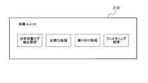
- FIG. 2 is a diagram illustrating a functional configuration example of the collection unit 210 configuring the monitoring subsystem 200.
- the collection unit 210 which is the first processing unit, sets the communication log file acquired from the log management subsystem 120 for each type of the detection device 110 that acquired the original communication log (raw log) of the communication log file. Perform the specified processing.
- the type of the detection device 110 means the type of product such as IDS / IPS, firewall, and anti-virus software that provides the functions of the sensor 111 and sensor manager 112 of the detection device 110.
- Information (ID, product name, etc.) specifying the type of the detection device 110 is included in, for example, a communication log file.
- the collection unit 210 of the present embodiment performs analysis target log extraction processing, communication log normalization processing, communication log distribution processing, and filtering processing as processing for the acquired communication log file.
- the collection unit 210 extracts a communication log to be processed (analyzed) by the monitoring subsystem 200 from communication logs included in the communication log file acquired from the log management subsystem 120.
- the communication log file (raw log) acquired from the log management subsystem 120 includes a log of an operation such as activation / deactivation of the sensor 111 of the detection device 110 (log unnecessary for analysis). Therefore, the collection unit 210 extracts only information that is a processing target (analysis target) of the monitoring subsystem 200 set in advance, and removes other information.
- the collection unit 210 normalizes the extracted communication log to be analyzed based on a predetermined rule. Specifically, the collection unit 210 arranges information such as date and time, protocol number, transmission source IP address (Internet Protocol Address), transmission source port, destination IP address, and destination port in the communication log in a common format. For example, the collection unit 210 unifies the standard (such as the Western calendar or the Japanese calendar) and format for describing the date and time, or unifies the IP address notation (notation system).
- the standard such as the Western calendar or the Japanese calendar
- format for describing the date and time or unifies the IP address notation (notation system).
- the acquired communication log may not include a part of information to be normalized.
- the collection unit 210 substitutes a preset default value, substitutes a value (Null) indicating that there is no information, performs analysis without complementing information, and the like. May be performed. Specifically, it is determined which action is taken according to the type of information that is lacking. Note that if the format of the communication log does not match the product specifications of the detection device 110 that acquired the communication log, or if the value in the acquired communication log is abnormal, the collection unit 210 uses the acquired communication log as an illegal communication. As a log, it is removed from the analysis target and saved in a database that stores unauthorized communication logs.
- the case where the value in the acquired communication log is abnormal is, for example, a case where the date and time value is a future date and time.
- the communication log distribution processing is performed by using the normalized communication log for each monitoring target determined by a contract or the like. This process is divided into logs. For example, when a service provided by the detection device 110 provided on the network is implemented in an environment used by the registered monitoring target device 100, one detection device 110 may detect communication of a plurality of monitoring target devices 100. obtain. In this case, the communication log file acquired by the detection device 110 includes communication logs in the plurality of monitoring target devices 100. Therefore, in order to analyze the communication log for each customer, in this embodiment, the collection unit 210 divides the communication log for each monitoring target device 100. Therefore, in the case where an embodiment based on the data center method is not employed and an individual detection device 110 is provided for each monitoring target, this communication log distribution processing is unnecessary. This is because in this case, the communication log has been distributed in advance.
- the distribution of communication logs is performed based on, for example, IP address range information.
- the IP address handled by the detection device 110 is in the range of “xx.x.1” to “xx.x.30” (“x” is a numerical value of 0 to 255).
- the IP addresses assigned to the monitoring target apparatus 100 of the customer A are “xx.x.1” to “xx.x.10”.
- the IP addresses assigned to the monitoring target apparatus 100 of the customer B are “xx.x.11” to “xx.x.12”.
- the IP addresses assigned to the monitoring target device 100 of the customer C are “xx.x.13” to “xx.x.30”.
- the IP address range for each monitoring target device 100 is registered in the collection unit 210 in advance, so that the collection unit 210 has a communication log associated with any monitoring target device 100. You can determine whether it is a log and distribute it.
- the collection unit 210 determines whether or not the communication log distributed in the above-described distribution process is to be analyzed based on individual conditions and rules set for each customer. Determination items in this filtering process include a source IP address, a source port, a destination IP address, a destination port, and the like. That is, when the transmission source IP address has a specific value in a certain communication log, the collection unit 210 can perform processing such as excluding the communication log from the analysis target. In addition, when the detection date and time is set as a determination item, the collection unit 210 can perform processing so that only communication performed after a specific date and time is included in the analysis target.
- the collection unit 210 extracts and normalizes the communication log to be processed from the communication log file of the raw log acquired from the log management subsystem 120. Then, the collection unit 210 sends the processed communication log to the detection unit 220 at the subsequent stage.
- the execution means for performing the processing as described above is configured as a component for each small processing unit.
- processing unit blocks componentized processing unit blocks
- processing corresponding to various detection devices 110 can be easily configured.
- the content (processing unit) of the processing executed by each processing unit block is not particularly limited, but is set to such a content as to be compatible with various detection devices 110 by rearranging the processing unit blocks.
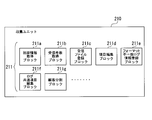
- FIG. 3 is a diagram illustrating a configuration example of the collection unit 210 configured by componentized processing unit blocks.
- the plurality of processing unit blocks 211 include an initial information acquisition block 211a, a received number acquisition block 211b, a received file registration block 211c, an item edit block 211d, a format mismatch log information registration block 211e, and a log common item edit.
- a block 211f and a customer division block 211d are included.
- the initial information acquisition block 211a is a processing unit block that performs processing for acquiring initial information.
- the reception number acquisition block 211b is a processing unit block that performs processing for acquiring the reception number.
- the received file registration block 211c is a processing unit block that performs processing for registering a received file.
- the item editing block 211d is a processing unit block that performs processing for editing an item.
- the format mismatch log information registration block 211e is a processing unit block for performing processing for registering log information whose format does not match.
- the log common item edit block 211f is a processing unit block that performs processing for editing a common item of a log.
- the customer division block 211d is a processing unit block that performs processing for dividing a customer.
- a collection unit 210 is configured by combining these processing unit blocks 211. In FIG. 3, only a part of the processing unit block 211 constituting the collection unit 210 is described.
- the processing unit blocks 211 such as the initial information acquisition block 211a, the reception number acquisition block 211b, and the reception file registration block 211c are responsible for the analysis target log extraction processing shown in FIG.
- the processing unit blocks 211 such as the item editing block 211d, the format mismatch log information registration block 211e, and the log common item editing block 211f are responsible for the normalization processing shown in FIG.
- the processing unit block 211 such as the customer division block 211g is responsible for the distribution process shown in FIG.
- the type and order of processing unit blocks 211 to be applied are set according to the type of detection device 110 (product type such as IDS / IPS, firewall, anti-virus software, etc.). That is, the application order (sequence) of the processing unit block 211 is prepared for each type of the detection device 110 of the monitoring target apparatus 100 set as a monitoring target. Then, according to the type of the detection device 110 that acquired the raw log of the communication log file to be processed, the processing set by each processing unit block 211 is performed by applying the sequence set to process the communication log file. .
- the type of detection device 110 product type such as IDS / IPS, firewall, anti-virus software, etc.
- each processing unit block 211 of the collection unit 210 is temporarily stored, for example, in the memory of a computer that constitutes the collection unit 210. Then, the communication log that has been processed by the collection unit 210 is sent together with the result to the detection unit 220 at the subsequent stage.
- FIG. 4 is a diagram illustrating a functional configuration example of the detection unit 220 that configures the monitoring subsystem 200.
- the detection unit 220 which is the second processing unit, is set for each classification of the detection device 110 that acquired the original communication log (raw log) of the communication log file as a process for the communication log acquired from the previous collection unit 210.
- the classification of the detection device 110 means the type of security device (IDS / IPS, firewall, etc.) that provides the functions of the sensor 111 and sensor manager 112 of the detection device 110.
- Information (ID, device name, etc.) specifying the classification of the detection device 110 is included in, for example, a communication log file.
- the detection unit 220 performs common information addition processing and log aggregation (eventing) processing as processing on the communication log processed by the collection unit 210.
- the detection unit 220 adds common information used for analyzing the communication log in the common information adding process.
- This common information is information related to items common to the communication logs.
- five items of attack pattern information original signature ID
- communication direction classification communication direction classification
- rule / action communication direction classification
- protocol number / name protocol number / name
- country code country code
- the attack pattern information is information that identifies an attack pattern that is given to each communication log by the monitoring subsystem 200.
- the detection device 110 detects any attack in the communication log (raw log), information (maker / signature information) specifying the detected attack is added to the communication log.
- the format of this information varies depending on the types of the monitoring target device 100 and the detection device 110. For this reason, in this embodiment, the detection unit 220 adds original information (attack pattern information) to the communication log.
- the communication indicated by the communication log is communication performed from the external network toward the internal network classified by the monitoring target apparatus 100, or conversely, from the internal network to the external network through the monitoring target apparatus 100.
- This is information indicating whether the communication has been performed.
- the meaning and importance of communication vary greatly depending on whether the communication source is an internal network or an external network.
- a case where there is a communication log regarding communication performed by an information processing apparatus infected with a computer virus will be described. In this case, if the communication is a communication sent from an external network, there is no particular problem because an information processing apparatus infected with a computer virus exists in the external network.
- the detection unit 220 assigns information on the communication direction classification indicating the communication direction in each communication log.
- the communication direction classification information refers to, for example, the network address or private address of the monitoring target device 100 to determine whether the transmission source IP address and the destination IP address are the internal network or the external network of the monitoring target device 100. Can be obtained.
- the rule action is information indicating an operation (action) performed by the detection device 110 in response to the communication when the monitoring target device 100 detects the communication.
- a security device such as IDS or IPS
- the device reports that it has detected dangerous communication or permits the communication based on the functions of those devices. Stop it. Therefore, information indicating what operation the detection unit 220 has performed is given.
- This rule / action information may also be added to the communication log by the security device that is the detection device 110.
- the name varies depending on the type of security device. For this reason, the monitoring subsystem 200 (the detection unit 220) gives a unified name.
- the protocol number / name is information indicating the type of communication protocol used for communication indicated by the communication log. Since there are several protocols such as TCP and UDP, the detection unit 220 gives information for identifying them. In the present embodiment, information indicating the type of communication protocol is determined based on, for example, the definition of IANA (Internet Assigned Number Number Authority).
- the country code is information indicating the transmission source and destination country of the communication indicated by the communication log, and is determined based on the transmission source IP address and the destination IP address of the communication log. This country code is mainly used as statistical information. This country code is used to analyze communication logs when the source and destination countries are considered to have different communication risks depending on whether they are countries where there are many attacks by unauthorized communications or whether they are domestic. It can also be used.
- the detection unit 220 adds information having high utility value in the analysis of the communication log to the communication log as information in a common format.
- the detection unit 220 aggregates communication logs as necessary, and generates an event that is analysis unit information.
- the information granularity of the communication log varies depending on the type of security device used as the detection device 110. For example, when the detection device 110 is a firewall, if one communication to be detected is detected, the communication is immediately detected by the sensor 111. On the other hand, when the detection device 110 is an IDS or the like, if it is determined that dangerous communication is being performed based on a plurality of communications according to a predetermined determination rule, the sensor 111 determines that it is dangerous. Detected communication is detected.
- the detection unit 220 When the detection device 110 is anti-virus software, the infection is detected by the sensor 111 after the target information processing apparatus is infected with a computer virus. Therefore, the weight of information in one communication log differs depending on the type of the detection device 110. Therefore, in the present embodiment, the detection unit 220 accumulates a plurality of communication logs according to the type of the detection device 110 to create an event, and arranges the granularity of information. That is, the detection unit 220 regards the communication log acquired by the detection device 110 having a large amount of information in one communication log as one event with a smaller number of communication logs. On the other hand, the detection unit 220 regards the communication log acquired by the detection device 110 having a small amount of information of one communication log as one event with a larger number of communication logs.
- the eventing process is different depending on whether the detection device 110 is a firewall or not.
- the detection device 110 is a firewall
- the amount of information in the communication log is small as described above (the communication is detected by the sensor 111 in one communication).
- the detection unit 220 generates an event by aggregating the acquired communication logs according to a predetermined rule.
- the communication log acquired by the detection device 110 other than the firewall has a larger amount of information in the communication log than the firewall (an event (communication or the like is detected by the sensor 111 via a plurality of communications)). .
- the detection unit 220 sets one log as one event.
- the event generation process when the detection device 110 is a firewall is performed as follows.
- the detection unit 220 collects communication logs conforming to a predetermined aggregation rule as an event based on the information included in the communication log and the common information added to the communication log in the processing for adding the common information. .
- the detection unit 220 is common information including a customer ID, a detection date, a transmission source IP address, a transmission source port number, a destination IP address, or a destination port number included in the communication log as determination items.
- Communication logs with the same communication direction classification, rule / action, and protocol number (name) are targeted. When the number of communication logs having these determination items in common becomes equal to or greater than a predetermined threshold, the detection unit 220 collects these communication logs as one event.
- the detection unit 220 includes, as determination items, a customer ID included in the communication log, a detection date, a transmission source IP address, a transmission source port number, a destination port number, and a communication direction classification that is common information.
- Target communication logs that have the same rule / action and protocol number (name).
- the detection unit 220 collects the communication logs and collects one communication log. An event.
- the detection unit 220 includes, as determination items, a customer ID included in the communication log, a detection date, a transmission source IP address, a transmission source port number, a destination IP address, and a communication direction classification that is common information.
- Target communication logs that have the same rule / action and protocol number (name).
- the detection unit 220 collects the communication logs and collects one communication log. An event.
- the execution means for performing the processing as described above is configured as a component for each small processing unit.
- processing unit blocks By combining these componentized processing unit blocks (hereinafter referred to as processing unit blocks), it is possible to design the processing contents (types of individual processing units, execution order, etc.) in the detection unit 220. Then, it is possible to easily configure processes corresponding to various monitoring target devices 100.
- the content (processing unit) of the processing executed by each processing unit block is not particularly limited, but is set to such a content as to be compatible with various monitoring target devices 100 by rearranging the processing unit blocks.
- FIG. 5 is a diagram showing a configuration example of the detection unit 220 configured by componentized processing unit blocks.
- the plurality of processing unit blocks 221 include a unique identification information addition block 221a, a communication direction division addition block 221b, a rule / action addition block 221c, a protocol number / name addition block 221d, a country code addition block 221e, An aggregation rule determination block 221f, a host / scan aggregation block 221g, and a port / scan aggregation block 221h are included.
- the unique identification information addition block 221a is a processing unit block to which unique identification information is added.
- the communication direction division addition block 221b is a processing unit block for adding a communication direction division.
- the rule / action addition block 221c is a processing unit block to which a rule / action is added.
- the protocol number / name addition block 221d is a processing unit block for adding a protocol number / name.
- the country code addition block 221e is a processing unit block for adding a country code.
- the aggregation rule determination block 221f is a processing unit block for determining an aggregation rule.
- the host scan aggregation block 221g is a processing unit block that aggregates host scans.
- the port scan aggregation block 221h is a processing unit block that aggregates port scans.
- the detection unit 220 is configured by combining these processing unit blocks 221. In FIG. 5, only a part of the processing unit block 221 constituting the detection unit 220 is shown.
- the processing unit blocks 221 such as the unique identification information addition block 221a, the communication direction division addition block 221b, the rule / action addition block 221c, the protocol number / name addition block 221d, and the country code addition block 221e are the same as shown in FIG. responsible for information addition processing.
- the processing unit blocks 221 such as the aggregation rule determination block 221f, the host / scan aggregation block 221g, and the port / scan aggregation block 221h are responsible for the log aggregation (eventing) processing shown in FIG.
- the type and order of the processing unit blocks 221 to be applied are set according to the type of the monitoring target device 100 (type of security device). That is, the application order (sequence) of the processing unit block 221 is prepared for each type of the monitoring target device 100 set as the monitoring target. Then, according to the type of the monitoring target device 100 from which the raw log of the processing target communication log file is acquired, the sequence set for processing the communication log file is applied, and the processing by each processing unit block 221 I do.
- the result of the common information addition process and the log aggregation process performed by each processing unit block 221 of the detection unit 220 is temporarily stored in, for example, the memory of a computer that configures the detection unit 220. Then, the result obtained together with the event obtained by collecting the communication logs is sent to the analysis unit 230 at the subsequent stage.
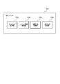
- FIG. 6 is a diagram illustrating a functional configuration example of the analysis unit 230 configuring the monitoring subsystem 200.
- the analysis unit 230 which is the third processing unit, includes an individual analysis processing unit 230a, an event accumulation processing unit 230b, a correlation analysis processing unit 230c, and an incremental analysis processing unit 230d. .
- the individual analysis processing unit 230a determines whether there is a problem communication for the event generated by the detection unit 220 individually. Specifically, the individual analysis processing unit 230a compares (matches) each event with a list (so-called black list) related to unauthorized communication, and determines that the communication indicated by the event is unauthorized communication.
- the unauthorized communication list registers, for example, IP addresses related to problematic communication.
- the individual analysis processing unit 230a determines that the communication is an unauthorized communication if either the transmission source IP address or the destination IP address of the communication indicated in the event matches the IP address registered in the list. .
- the individual analysis processing unit 230a determines whether or not to perform an analysis based on the correlation between events for an event that is not determined to be a problematic communication by collating with the problematic communication list. That is, the individual analysis processing unit 230a functions as a classification unit (classification unit) that classifies an event into an event that performs an analysis based on a correlation and an event that does not perform an analysis based on a correlation.
- classification unit classification unit
- the determination as to whether or not to analyze based on the correlation is, for example, information on the communication log included in the event, or common information (attack pattern information) added to the communication log in the common information addition processing by the detection unit 220. , Based on the content of communication specified by the communication direction type).
- the event that is the subject of the analysis based on the correlation is then subjected to accumulation processing by the event accumulation processing unit 230b.
- the analysis unit 230 does not perform subsequent processing (that is, excluded from correlation analysis or incremental analysis), and the event is manually analyzed by the analysis unit 240. Send to.
- the event accumulation processing unit 230b accumulates the events subjected to the analysis based on the correlation by the individual analysis processing unit 230a based on a predetermined rule, and an event sequence (event / event) composed of one or a plurality of events. Chain). Further, the event accumulation processing unit 230b accumulates an event sequence based on a predetermined rule, and includes one or a plurality of event sequences, and a candidate for an event to be detected by analysis (incident candy date: Called detection event candidate). That is, the event accumulation processing unit 230b functions as an accumulation unit (accumulation unit) that accumulates events and generates detection event candidates.
- the event accumulation processing unit 230b has the same attack by the same attacker (access), the same attack means (access method), and the same attack with respect to an attack by unauthorized access from a server or the like existing in the external network.
- Communication that is assumed to be a target is extracted, and the extracted communication is collected as a detection event candidate.
- the extraction of the communication assumed to be the attack by the same attacker, the same attack means, the same attack target, etc. is performed based on information such as the transmission source IP address, the communication direction classification, and the detection date.
- the acquisition of the communication log by the detection device 110 and the log management subsystem 120 and the processing by the collection unit 210 and the detection unit 220 of the monitoring subsystem 200 are performed at any time. For this reason, events are generated one after another as time passes. If the newly generated event is determined by the event accumulation processing unit 230b to correspond to the target event included in the specific detection event candidate, it is incorporated into the detection event candidate. Therefore, the detection event candidate to which a new event is added becomes a target of processing by the correlation analysis processing unit 230c and the incremental analysis processing unit 230d each time.
- the correlation analysis processing unit (analyzing unit, analyzing unit) 230c determines whether or not a detected event candidate that is a combination of a plurality of events is a problematic communication by performing an attack pattern combination determination and a case number threshold excess determination. To do.
- the correlation analysis processing unit 230c determines the communication direction, source / destination IP address (range), source / destination port, rule / action, source / destination country in the communication log included in the detection event candidate. Whether the communication specified by the detection event candidate is a problematic communication based on the type of communication specified based on information such as code and session data and the combination of attack pattern information (original signature ID) Judging. That is, the correlation analysis processing unit 230c determines whether or not the communication content specified by the detected event candidate corresponds to the attack pattern specified by the attack pattern information. Here, the correlation analysis processing unit 230c determines whether or not there is a high possibility that an attack (exploitation or disappearance of information) is actually performed through this communication.
- the correlation analysis processing unit 230c determines the communication direction, source / destination IP address (range), source / destination port, rule / action, source / destination country in the communication log included in the detection event candidate. Based on information such as the code and the number of cases, it is determined whether or not the communication specified by the detected event candidate is a problematic communication. Here, the correlation analysis processing unit 230c determines whether or not the number of times of communication specified by the detected event candidate is significantly increased compared to the usual case.
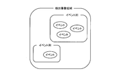
- FIG. 7 is a diagram showing the concept of correlation analysis.
- the event accumulation processing unit 230b of the analysis unit 230 accumulates events that are targets of accumulation processing among events acquired from the detection unit 220, generates an event sequence, and further generates detection event candidates. Then, for each detection event candidate, the event accumulation processing unit 230b performs the above attack pattern combination determination and the number threshold value excess determination based on the correlation between the event sequence and events included in each detection event candidate.
- the incremental analysis processing unit 230d determines whether a detected event candidate that is a combination of a plurality of events is a problem by performing event change determination, attack means increase determination, attack number increase determination, and attack destination increase determination. It is determined whether or not there is communication. For example, regarding an attack caused by unauthorized access from a server or the like that exists in an external network, the same attack may continue repeatedly instead of a single attack, the attack content may change, or the attack destination may increase. Therefore, the incremental analysis processing unit 230d determines whether there is a change in an event that is suspected to be problematic communication based on a communication log included in the detected event candidate.
- the incremental analysis processing unit 230d based on the analysis result for a certain period (for example, one day) by the correlation analysis processing unit 230c, analyzes rules (for analysis for each detected event candidate) ( Changes in the application of rules for determining attack pattern combinations and determining the number of cases exceeding the threshold value are determined.
- rules for analysis for each detected event candidate
- the incremental analysis processing unit 230d determines that the communication included in the detection event candidate to be determined is a problem communication. Judge that there is.
- the incremental analysis processing unit 230d determines It is determined that the communication included in the target detection event candidate is a problematic communication. In the determination of the increase in the number of attacks, communication with the same attack pattern information to be confirmed (same attack technique) and communication from the same attack source continue, and the number of events per unit time due to those communication increases. In such a case, the incremental analysis processing unit 230d determines that the communication included in the detection event candidate to be determined is a problematic communication. In the attack destination increase determination, when the attack destination or the connection destination increases, the incremental analysis processing unit 230d determines that the communication included in the detection event candidate to be determined is a problem communication.
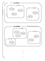
- FIG. 8A and 8B are diagrams illustrating the concept of incremental analysis.
- FIG. 8A shows a configuration example of one detection event candidate that is a target of correlation analysis during a certain analysis.
- FIG. 8B shows a configuration example of the same detection event candidate at the time of the next analysis.
- the configuration at the time of the previous analysis see FIG. 8A
- the configuration at the time of the current analysis see FIG. 8B
- an event sequence (event sequence shaded in FIG. 8B) that was not included at the time of the previous analysis is newly included. For this reason, this detected event candidate is determined to be a problem communication in any of the above-described event change determination, attack means increase determination, attack number increase determination, or attack destination increase determination.
- the analysis unit 230 sends the analysis result for each detection event candidate to the manual analysis unit 240 in association with the detection event candidate to be analyzed.
- the analysis result by the analysis unit 230 indicates whether each detection event candidate is unauthorized communication, problematic communication (communication that may be unauthorized communication), or non-illegal communication.
- the individual analysis processing unit 230a, the event accumulation processing unit 230b, the correlation analysis processing unit 230c, and the incremental analysis processing unit 230d that perform the processing as described above are configured as components for each small processing unit.
- processing unit blocks componentized processing unit blocks
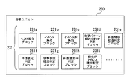
- FIG. 9 is a diagram illustrating a configuration example of the analysis unit 230 including the individual analysis processing unit 230a including the componentized processing unit blocks, the event accumulation processing unit 230b, the correlation analysis processing unit 230c, and the incremental analysis processing unit 230d. is there.
- the plurality of processing unit blocks 231 include a list matching block 231a, an event aggregation block 231b, an event string aggregation block 231c, an attack pattern combination determination block 231d, a case number threshold excess determination block 231e, and an event change determination block 231f.
- Attack means increase determination block 231g, number increase rate determination block 231h, and destination IP address increase determination block 231i.
- the list collation block 231a is a processing unit block that performs processing for collating lists.
- the event aggregation block 231b is a processing unit block that performs processing for aggregating events.
- the event string aggregation block 231c is a processing unit block that performs processing for aggregating event strings.
- the attack pattern combination determination block 231d is a processing unit block that performs a process of determining an attack pattern combination.
- the number-of-threshold-threshold excess determination block 231e is a processing unit block that performs processing for determining whether the number of cases exceeds the threshold.
- the event change determination block 231f is a processing unit block that performs processing for determining whether an event has changed.
- the attack means increase determination block 231g is a processing unit block that performs processing for determining whether or not the attack means is increasing.
- the case increase rate determination block 231h is a processing unit block that performs processing for determining the increase rate of the number of cases.
- the destination IP address increase determination block 231i is a processing unit block that performs processing to determine whether the destination IP address has increased.
- the processing unit blocks 231 such as the event aggregation block 231b and the event string aggregation block 231c are responsible for the generation of event strings and detected event candidates by the event accumulation processing unit 230b.
- the processing unit blocks 231 such as the attack pattern combination determination block 231d and the case threshold value excess determination block 231e are responsible for analysis by the correlation analysis processing unit 230c.
- the processing unit blocks 231 such as the event change determination block 231f, the attack means increase determination block 231g, the number of cases increase rate determination block 231h, and the destination IP address increase determination block 231i are responsible for analysis by the incremental analysis processing unit 230d.
- the columns of these processing unit blocks 231 constitute an individual analysis processing unit 230a, an event accumulation processing unit 230b, a correlation analysis processing unit 230c, and an incremental analysis processing unit 230d.
- a plurality of individual analysis processing units 230a, a plurality of event accumulation processing units 230b, a plurality of correlation analysis processing units 230c, and a plurality of incremental analysis processing units 230d are prepared, and each can execute processing in parallel and asynchronously.
- each processing unit block 231 of the analysis unit 230 The results of the individual analysis processing, event accumulation processing, correlation analysis processing, and incremental analysis processing performed by each processing unit block 231 of the analysis unit 230 are temporarily stored in, for example, the memory of a computer constituting the analysis unit 230. Then, the detection event candidates that have been subjected to various analysis processes and the events that have not been collected in the individual analysis process are sent to the manual analysis unit 240 at the subsequent stage.
- FIG. 10 is a diagram illustrating a functional configuration example of the manual analysis unit 240 of the monitoring subsystem 200.
- the manual analysis unit 240 which is the fourth processing unit, stores information on events, event sequences and detection event candidates obtained by the above-described processes by the detection unit 220 and the analysis unit 230, and analysis results by the analysis unit 230. 241 is stored and managed. Further, in response to a request from the terminal device 300, the manual analysis unit 240 uses the transmission / reception unit 242 to store information on events, event strings, and detection event candidates stored in the storage device 241, and analysis results from the analysis unit 230. Is sent to the terminal device 300. Further, the manual analysis unit 240 acquires information given to these pieces of information in the terminal device 300 by the transmission / reception unit 242 and adds and manages the acquired information to each stored information.
- the security monitoring system monitors communication in the monitoring target device 100 and detects problematic communication in real time.
- the system is not a system that analyzes the accumulated communication log file and later discovers that there was a problem communication. Therefore, it is desirable that the communication log file is transmitted between the processing units in the monitoring subsystem 200 for detecting problematic communication from the communication log as fast as possible.
- connectionless communication is performed instead of connection communication such as TCP (Transmission Control Protocol).
- TCP Transmission Control Protocol
- connectionless communication unlike the connection communication, it is not determined whether or not individual communication between the processing units in the monitoring subsystem 200 has been performed normally. . Therefore, even if the communication log file to be processed is lost in the communication between the processing units, the fact cannot be recognized. For this reason, when a communication log file to be processed is lost during processing in the monitoring subsystem 200, a mechanism for detecting the fact is necessary.
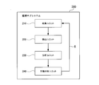
- FIG. 11 is a diagram for explaining a communication log file transmission method according to this embodiment.
- FIG. 11 shows a processing unit row (a row constituted by the collection unit 210, the detection unit 220, the analysis unit 230, and the manual analysis unit 240) constituting the monitoring subsystem 200.
- the communication log is normally transmitted from the first processing unit (collection unit 210) to the last processing unit (manual analysis unit 240). A configuration for feeding back to the processing unit is provided.
- the manual analysis unit 240 which is the last processing unit of the monitoring subsystem 200, receives information on events and detection event candidates from the analysis unit 230, the manual analysis unit 240 has acquired the communication logs constituting these events and detection event candidates. Is notified to the collection unit 210 which is the first processing unit (see arrow R in FIG. 11). As a result, the first collection unit 210 recognizes that the communication log file to be processed has reached the last processing unit (manual analysis unit 240) through each processing unit without being lost. The collection unit 210 transmits a communication log file to the detection unit 220, which is a subsequent processing unit, and then retransmits the communication log file, for example, at regular intervals until a predetermined retransmission stop condition is satisfied.
- the retransmission stop condition it may be set on the condition that a notification indicating that the communication log file has been acquired from the manual analysis unit 240 is received within a certain time from the previous transmission.
- the retransmission stop condition in this way, if the communication log file to be processed disappears for some reason and does not reach the manual analysis unit 240, the manual analysis unit 240 notifies the collection unit 210. (Retransmission stop condition is not satisfied). For this reason, after the lapse of a certain time, the same communication log file is retransmitted from the collection unit 210.
- the retransmission stop condition it may be set on the condition that the same communication log file is transmitted a predetermined number of times. As yet another example of the retransmission stop condition, it may be set on the condition that a predetermined time has elapsed since the first transmission.
- the retransmission stop condition in this manner, when the communication log file is not transmitted normally a predetermined number of times, a failure has occurred in the monitoring subsystem 200, not the loss due to the connectionless communication specification. It can be judged. Therefore, in this case, the retransmission of the communication log file is stopped and the system operator is notified that a failure has occurred in the monitoring subsystem 200.
- the counting of the number of times of transmission of the same communication log file may be realized, for example, by the collection unit 210 counting the number of transmissions when transmitting the communication log file and holding the counted number of transmissions. Good.
- the communication log file to be processed when the communication log file to be processed does not reach the manual analysis unit 240, the communication log file is not generated at any stage in the transmission of the communication log file between the processing units. I know it was lost. On the other hand, it is impossible to identify where the communication log file has been lost. However, in this embodiment, unless the communication log file reaches the manual analysis unit 240, the processing (analysis) for the communication log file is not completed. Therefore, as described above, the manual analysis unit 240 located at the end of the processing unit row of the monitoring subsystem 200 is set as the inspection position.
- the communication log file is newly transferred from the first collection unit 210 to the last manual analysis unit 240. Is transmitted. Therefore, for example, when a communication log file is lost between the analysis unit 230 and the manual analysis unit 240, the same communication log is processed even though the processing by the detection unit 220 and the analysis unit 230 is completed for the communication log file. The file will be transmitted again.
- each processing unit performs processing on the retransmitted communication log file regardless of whether or not processing was performed at the previous transmission.
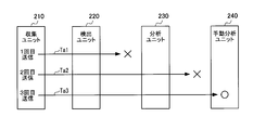
- FIG. 12 is a diagram illustrating an example of communication log file transmission according to the present embodiment.
- “x” indicates that the communication log file has been lost.
- “ ⁇ ” indicates that the communication log file has reached the manual analysis unit 240.
- An arrow Ta1 indicates the first transmission.
- An arrow Ta2 indicates the second transmission.
- Arrow Ta3 indicates the third transmission.
- a certain communication log file is transmitted from the collection unit 210 to the detection unit 220 in the first transmission, and after being processed by the detection unit 220, is transmitted from the detection unit 220 to the analysis unit 230. It disappears without reaching the analysis unit 230 (see arrow Ta1). In this case, notification indicating that the communication log file has been acquired from the manual analysis unit 240 is not sent to the collection unit 210.
- the collection unit 210 retransmits the communication log file. That is, the collection unit 210 transmits the communication log file for the second time.
- the result of the processing of the detection unit 220 performed on the communication log file related to the first transmission disappears together with the communication log file related to the first transmission. For this reason, the detection unit 220 performs processing on the retransmitted communication log file.
- the communication log file is transmitted from the analysis unit 230 to the manual analysis unit 240 through processing by the analysis unit 230, but is lost without reaching the manual analysis unit 240. (See arrow Ta2). Also in this case, the collection unit 210 is not notified that the communication log file has been acquired from the manual analysis unit 240. Therefore, the collection unit 210 retransmits the communication log file. That is, the collection unit 210 performs the third transmission of the communication log file. The result of the processing of the detection unit 220 and the analysis unit 230 performed on the communication log file related to the second transmission disappears together with the communication log file related to the second transmission. For this reason, the detection unit 220 and the analysis unit 230 perform processing on the retransmitted communication log file.
- the communication log file in the third transmission, the communication log file reaches the manual analysis unit 240 and is stored in the storage device 241 (see arrow Ta3). Then, a notification indicating that the communication log file has arrived from the manual analysis unit 240 to the collection unit 210 is made. Thereby, the retransmission of the communication log file is stopped.
- the communication log file may be retransmitted even if it is not lost.
- the waiting time for retransmission in the collection unit 210 has elapsed before notification from the manual analysis unit 240 because the processing by the processing unit in the middle took time.
- the same communication log file (detection event candidate) and its processing result may reach the manual analysis unit 240 a plurality of times and be stored in the storage device 241 redundantly. Therefore, in such a case, the communication log file and the processing result transmitted last from the collection unit 210 are used as valid data.
- the valid data is data to be transmitted to the terminal device 300 and displayed on the display unit 330 (see FIG. 15), which will be described later.
- FIG. 13 is a diagram showing another example of communication log file transmission according to the present embodiment.
- “x” indicates that the communication log file has been lost.
- “ ⁇ ” indicates that the communication log file has reached the manual analysis unit 240.
- Arrow Tb1 indicates the first transmission.
- Arrow Tb2 indicates the second transmission.
- Arrow Tb3 indicates the third transmission.
- the communication log file related to the second transmission reaches the analysis unit 230.
- the communication log file disappears without reaching the analysis unit 230 after being processed by the detection unit 220 (see arrow Tb1).
- the communication log file reaches the manual analysis unit 240 without disappearing (see arrow Tb2).
- the second transmission takes time for the intermediate processing.
- the third transmission is performed before the manual analysis unit 240 notifies the collection unit 210 (see arrow Tb3).
- it takes time to process the communication log file related to the second transmission.
- the communication log file related to the third transmission reaches the manual analysis unit 240 earlier than the communication log file related to the second transmission. In this case, regardless of the order of arrival at the manual analysis unit 240, the result of the processing performed on the communication log file related to the third (last) transmission is treated as valid data.
- data other than valid data among the duplicated data related to the same communication log file that has reached the manual analysis unit 240 and stored in the storage device 241 may be deleted, or may be left stored in the storage device 241.
- FIG. 14 is a diagram illustrating still another example of communication log file transmission according to the present embodiment.
- “x” indicates that the communication log file has been lost.
- “ ⁇ ” indicates that the communication log file has reached the manual analysis unit 240.
- Arrow Tc1 indicates the first transmission.
- Arrow Tc2 indicates the second transmission.
- Arrow Tc3 indicates the third transmission.
- the communication log file may be retransmitted before the previously transmitted communication log file reaches the manual analysis unit 240. In such a case, a communication log file transmitted later may be lost on the way.
- the communication log file is retransmitted (third transmission) before the communication log file related to the second transmission reaches the manual analysis unit 240.
- the communication log file related to the third transmission disappears without reaching the manual analysis unit 240.
- the communication log file that reaches the manual analysis unit 240 and is stored in the storage device 241 is only the communication log file related to the second transmission. For this reason, the data regarding the communication log file related to the second transmission is handled as valid data.
- each processing unit is merely an example of the operation for the retransmitted communication log file, and is not limited to the above operation.
- the case where the processing result of each processing unit is temporarily stored in the memory of a computer configuring each processing unit has been described above.
- the present embodiment is not limited to such a configuration.
- a configuration may be adopted in which the processing result of each processing unit is stored and managed in a predetermined database. In this case, even if the communication log file is lost during transmission of each processing unit, the processing result of the processing already performed remains in the database. In such a case, if the processing unit performs processing on the retransmitted communication log file, the detection accuracy of the problematic communication is affected.
- a retransmitted communication log file is a processed communication log file in a certain processing unit
- the information on the processing result that already exists may be replaced with the information on the current processing result. That is, the previous processing result related to the communication log file is discarded.
- the processing for the retransmitted communication log file is skipped and skipped.
- the communication log file may be sent to the processing unit.
- flag data indicating retransmission may be added, or information indicating the number of transmissions may be added.
- the collection unit 210 does not count the number of transmissions of the same communication log file. Also, it is possible to recognize how many times the same communication log file has been transmitted based on the notification from the manual analysis unit 240.
- FIG. 15 is a diagram illustrating a functional configuration example of the terminal device 300.
- the terminal device 300 includes a transmission / reception unit 310 and a data processing unit 320.
- the terminal device 300 includes a display unit 330 realized by a liquid crystal display or the like, and an operation unit 340 realized by an input device such as a keyboard or a mouse.
- the transmission / reception unit 310 is an interface that communicates with the manual analysis unit 240 of the monitoring subsystem 200.
- the transmission / reception unit 310 receives from the manual analysis unit 240 information on events, event strings, and detection event candidates obtained by the processing of the detection unit 220 and the analysis unit 230, and analysis results by the analysis unit 230.
- the transmission / reception unit 310 transmits information input by operating the operation unit 340 to the manual analysis unit 240 of the monitoring subsystem 200.
- the transmission / reception unit 310 transmits the communication to a terminal device (not shown) operated by the operator of the monitoring target device 100. Notify discovery.
- the data processing unit 320 generates an analysis screen based on the information of the event, the event string, and the detection event candidate acquired from the manual analysis unit 240 of the monitoring subsystem 200 by the transmission / reception unit 310 and the analysis result by the analysis unit 230. In addition, the data processing unit 320 causes the display unit 330 to display the generated analysis screen.
- FIG. 16 is a diagram illustrating a configuration example of the analysis screen.
- the analysis screen displayed on the display unit 330 includes a search condition display area 331, a detection event candidate display area 332, an event string display area 333, an event display area 334, a comment display area 335, an importance level.
- the display area 336 includes six display areas.
- search conditions such as detection event candidates displayed in the detection event candidate display area 332 are displayed.
- this search condition for example, an appropriate condition may be set initially. Further, for example, this search condition may be set by an analyzer inputting a desired search condition by operating the operation unit 340.
- the detection event candidate to be searched includes a detection event candidate composed of only one event string or one event.
- a single event taken out as the analysis based on the correlation is not performed by the individual analysis processing unit 230a of the analysis unit 230 can be set as a search target as a detection event candidate including one event.
- the detection event candidate displayed in the search condition display area 331 the detection event candidate searched by the search condition displayed in the search condition display area 331 and the processing result by the analysis unit 230 of the monitoring subsystem 200 are displayed.
- the event string display area 333 the event string and the monitoring subsystem 200 included in the detected event candidates displayed in the detected event candidate display area 332 (that is, searched with the search condition specified in the search condition display area 331).
- the processing result by the analysis unit 230 is displayed.
- event display area 334 analysis of events included in the detection event candidates displayed in the detection event candidate display area 332 (that is, searched by the search condition specified in the search condition display area 331) and the monitoring subsystem 200 is performed.
- the processing result by the unit 230 is displayed.
- the importance level display area 336 shows an evaluation level for evaluating the detection event candidate displayed in the detection event candidate display area 332 (that is, searched with the search condition specified in the search condition display area 331). It is.
- the evaluation level is, for example, the necessity for communication specified by the detection event candidate, such as whether it is necessary to take immediate measures or whether it is necessary to detect and evaluate the same type of communication continuously. It is a value of importance that is divided in stages according to the correspondence.
- the importance display area 336 is an input interface that accepts selection of importance levels by an analyst. The analyst evaluates the detected detection event candidate by selecting one of the importance levels displayed in the importance display area 336.
- the analyst can search for detection event candidates, event strings, and events that are searched based on the search conditions that are initially displayed in the search condition display area 331 of the display unit 330 or the search conditions that are input by the operation unit 340. Based on this, the communication of the monitoring target device 100 is evaluated (manual analysis). If a problematic communication is found, the analyst operates the operation unit 340 to input a comment and an importance level corresponding to the content of the communication (contents of the problem), and monitor via the transmission / reception unit 310. The operator of the target device 100 is notified.
- communication that is determined to be unauthorized communication (such as an attack or unauthorized information leakage) by collation with the list in the analysis unit 230 or communication that has been determined to be unauthorized communication by analysis in the analysis unit 230 is analyzed. It is possible to make it an object of notification to the operator of the monitoring target device 100 without requiring evaluation by the operator.
- FIG. 17 is a diagram showing a hardware (computer) configuration example applicable to configure each processing unit and terminal device 300 of the monitoring subsystem 200 of this embodiment.
- the computer shown in FIG. 17 includes a central processing unit (CPU) 10a that is a calculation unit and a memory 10c that is a main storage unit.
- the computer shown in FIG. 17 includes a magnetic disk device (HDD: Hard Disk Drive) 10g, a network interface 10f, a display mechanism 10d including a display device, an input device 10i such as a keyboard and a mouse, and the like as external devices.
- HDD Hard Disk Drive
- the memory 10c and the display mechanism 10d are connected to the CPU 10a via the system controller 10b.
- the network interface 10f, the magnetic disk device 10g, and the input device 10i are connected to the system controller 10b via the I / O controller 10e.
- Each component is connected by various buses such as a system bus and an input / output bus.
- FIG. 17 merely exemplifies a hardware configuration of a computer suitable for applying the present embodiment.
- This embodiment can be widely applied to information processing apparatuses that can acquire and process a communication log file in the monitoring target apparatus 100 in real time and detect unauthorized communication or problematic communication. That is, the configuration for realizing the present embodiment is not limited to the configuration shown in FIG.
- the OS program and application programs are stored in the magnetic disk device 10g. These programs are read into the memory 10c and executed by the CPU 10a, whereby various functions in the processing units 210 to 240 and the terminal device 300 of the monitoring subsystem 200 in the present embodiment are realized.
- the present invention may be applied to a log analysis system.
Abstract
Description
本願は、2014年3月31日に、日本に出願された特願2014-074606号に基づき優先権を主張し、その内容をここに援用する。 The present invention relates to a log analysis system that acquires and analyzes logs generated in a target system.
This application claims priority based on Japanese Patent Application No. 2014-074606 filed in Japan on March 31, 2014, the contents of which are incorporated herein by reference.
上記のログ分析システムにおいて、処理装置の第1処理ユニットは、取得装置の種類に対応して設定された規則に基づいて、第1処理ユニットを構成する処理単位ブロックの種類および適用順を特定して処理を行ってもよい。
上記のログ分析システムにおいて、処理装置の第2処理ユニットは、検知ログに前記共通情報を付加し、情報粒度を揃えるために行われる個々の処理ごとに個別にコンポーネント化された処理単位ブロックを組み合わせて構成されてもよい。
上記のログ分析システムにおいて、処理装置の第2処理ユニットは、監視対象単位の種類に対応して設定された規則に基づいて、第2処理ユニットを構成する処理単位ブロックの種類および適用順を特定して処理を行ってもよい。
上記のログ分析システムにおいて、処理装置の第3処理ユニットは、第2処理ユニットから出力された分析単位情報を、相関関係の分析が行われる分析単位情報と相関関係の分析が行われない分析単位情報とに分ける分類手段と、相関関係の分析が行われる分析単位情報を集積して検出対象の事象の候補とする集積手段と、この検出対象の事象の候補に対して分析単位情報の相関関係の分析を含む判定処理を行って、この検出対象の事象の候補が前記特定の性質を有する検知対象処理か否かを判断する分析手段と、を備えてもよい。
上記のログ分析システムにおいて、処理装置の第3処理ユニットに含まれる分析手段は、検出対象の事象の候補が前記特定の性質を有する検知対象処理か否かを判断するために設定された判定条件に基づいて、相関関係の分析を含む判定処理における個々の処理ごとに個別にコンポーネント化された処理単位ブロックを組み合わせて構成されてもよい。
上記のログ分析システムにおいて、処理装置の第2処理ユニットは、検知ログの情報粒度を揃える処理として、この検知ログが一つの検知対象処理に対して検知ログが取得される監視対象システムから取得された検知ログである場合は、予め設定された集約条件に基づいて集約された複数の検知ログを一つの分析単位情報としてもよい。一方、処理装置の第2処理ユニットは、検知ログの情報粒度を揃える処理として、この検知ログが複数の検知対象処理に対して検知ログが取得される監視対象システムから取得された検知ログである場合は、一つの検知ログを一つの分析単位情報としてもよい。 In the log analysis system described above, the first processing unit of the processing apparatus may be configured by combining processing unit blocks that are individually componentized for each processing performed for normalization and distribution of the detection log. .
In the log analysis system, the first processing unit of the processing device specifies the type and application order of the processing unit blocks constituting the first processing unit based on a rule set corresponding to the type of the acquisition device. May be processed.
In the log analysis system, the second processing unit of the processing device combines the processing unit blocks individually componentized for each processing performed to add the common information to the detection log and to uniform the information granularity. May be configured.
In the above log analysis system, the second processing unit of the processing device specifies the type and application order of the processing unit blocks constituting the second processing unit based on a rule set corresponding to the type of the monitoring target unit. Then, the processing may be performed.
In the log analysis system, the third processing unit of the processing apparatus uses the analysis unit information output from the second processing unit as an analysis unit in which the correlation analysis is not performed and the analysis unit information in which the correlation analysis is performed. Classification means to divide into information, accumulation means for collecting analysis unit information for which correlation analysis is performed and making it a candidate for an event to be detected, and correlation of analysis unit information to this candidate for an event to be detected Analysis means for performing a determination process including the above analysis to determine whether or not the candidate event to be detected is a detection target process having the specific property.
In the log analysis system, the analysis unit included in the third processing unit of the processing device has a determination condition set to determine whether or not the detection target event candidate is a detection target process having the specific property Based on the above, processing unit blocks that are individually componentized for each process in the determination process including the analysis of the correlation may be combined.
In the log analysis system, the second processing unit of the processing device acquires the detection log from a monitoring target system in which a detection log is acquired for one detection target process as a process for aligning the information granularity of the detection log. A plurality of detection logs aggregated based on a preset aggregation condition may be used as one piece of analysis unit information. On the other hand, the second processing unit of the processing device is a detection log acquired from a monitoring target system in which detection logs are acquired for a plurality of detection target processes as processing for uniforming the information granularity of the detection log. In this case, one detection log may be used as one piece of analysis unit information.
以下では、検査対象のシステムから検知対象処理のログ(検知ログ)を取得して分析する本実施形態のログ分析システムを、検知対象処理としてネットワーク上の通信を監視し、検知ログとして通信ログを取得し分析するセキュリティ監視システムに適用した場合を例として説明する。ネットワークに接続されたサーバ等の情報処理装置では、ネットワークを介して様々な通信が行われる。本実施形態のセキュリティ監視システム(SOC(Security Operation Center)システム)は、監視対象装置である情報処理装置の通信を監視し、抽出すべき特定の性質を有する検知対象処理の一例として、外部からの不正なアクセスや内部からの不正な情報流出等のような問題のある通信を抽出する。 Hereinafter, embodiments of the present invention will be described in detail with reference to the accompanying drawings.
In the following, the log analysis system of this embodiment that acquires and analyzes the log (detection log) of the detection target process from the inspection target system, monitors the communication on the network as the detection target process, and displays the communication log as the detection log. A case where the present invention is applied to a security monitoring system that acquires and analyzes will be described as an example. An information processing apparatus such as a server connected to a network performs various communications via the network. The security monitoring system (SOC (Security Operation Center) system) of the present embodiment monitors communication of an information processing apparatus that is a monitoring target apparatus, and as an example of a detection target process having a specific property to be extracted, Extract communications with problems such as unauthorized access and unauthorized information leakage from inside.
図1は、本実施形態のセキュリティ監視システムの構成例を示す図である。
図1に示すように、本実施形態によるセキュリティ監視システムは、監視対象装置100における通信を監視して通信ログを取得する取得装置としての検知デバイス110、ログ取得エージェント121およびログ管理サブシステム120を備える。また、本実施形態によるセキュリティ監視システムは、取得された通信ログを処理して問題のある通信を抽出する処理装置としての監視サブシステム200を備える。さらに、本実施形態によるセキュリティ監視システムは、監視サブシステム200による処理の結果を出力する出力装置としての端末装置300を備える。図1に示す構成において、監視対象装置100に搭載される検知デバイス110およびログ取得エージェント121と、ログ管理サブシステム120、監視サブシステム200および端末装置300とを区別するために、監視対象装置100に搭載される構成要素を対象側システムと呼び、ログ管理サブシステム120、監視サブシステム200および端末装置300をセンター側システムと呼ぶ場合がある。なお、図1において、監視対象装置100は1台のみが例示されているが、実際のシステムにおいては、複数の監視対象装置100における通信を監視対象とする。 <System configuration example>
FIG. 1 is a diagram illustrating a configuration example of a security monitoring system according to the present embodiment.
As shown in FIG. 1, the security monitoring system according to the present embodiment includes a
なお、本実施形態では、セキュリティ監視システムとしてのログ分析システムが、ネットワーク通信を監視対象として通信ログを取得する例について説明する。しかしながら、本実施形態の適用例はこれに限定されない。通信以外の種々の処理において生成される様々なログを取得し検査するために本実施形態のログ分析システムを適用することも可能である。 The
In the present embodiment, an example will be described in which a log analysis system as a security monitoring system acquires a communication log for monitoring network communication. However, the application example of this embodiment is not limited to this. It is also possible to apply the log analysis system of this embodiment to acquire and inspect various logs generated in various processes other than communication.
なお、図1に示す構成例では、ログ取得エージェント121を対象側システムとして監視対象装置100に搭載する構成を採用している。しかしながら本実施形態はこのような構成に限定されない。ログ取得エージェント121を監視対象装置100に搭載せずにセンター側システムとして構成しても良い。この場合、ネットワークを介して監視対象装置100に接続された独立のサーバ等としてログ取得エージェント121を構成しても良いし、ログ管理サブシステム120の機能の一つとしてログ取得エージェント121を実現しても良い。 The
In the configuration example illustrated in FIG. 1, a configuration is adopted in which the
図2は、監視サブシステム200を構成する収集ユニット210の機能構成例を示す図である。
第1処理ユニットである収集ユニット210は、ログ管理サブシステム120から取得した通信ログファイルに対して、その通信ログファイルの元の通信ログ(生ログ)を取得した検知デバイス110の種類ごとに設定された処理を行う。ここで、検知デバイス110の種類とは、検知デバイス110のセンサ111およびセンサ・マネージャ112の機能を提供するIDS/IPS、ファイア・ウォール、ウィルス対策ソフト等の製品の種別を意味する。なお、検知デバイス110の種類を特定する情報(ID、製品名等)は、例えば、通信ログファイルに含まれている。 <Function of collection unit>
FIG. 2 is a diagram illustrating a functional configuration example of the
The
図3に示す例では、複数の処理単位ブロック211は、初期情報取得ブロック211a、受信件数取得ブロック211b、受信ファイル登録ブロック211c、項目編集ブロック211d、フォーマット不一致ログ情報登録ブロック211e、ログ共通項目編集ブロック211f、顧客分割ブロック211dを含む。初期情報取得ブロック211aは、初期情報を取得する処理を行う処理単位ブロックである。受信件数取得ブロック211bは、受信件数を取得する処理を行う処理単位ブロックである。受信ファイル登録ブロック211cは、受信ファイルを登録する処理を行う処理単位ブロックである。項目編集ブロック211dは、項目を編集する処理を行う処理単位ブロックである。フォーマット不一致ログ情報登録ブロック211eは、フォーマットが不一致であるログの情報を登録する処理を行う処理単位ブロックである。ログ共通項目編集ブロック211fは、ログの共通項目を編集する処理を行う処理単位ブロックである。顧客分割ブロック211dは、顧客を分割する処理を行う処理単位ブロックである。これらの処理単位ブロック211が組み合わされて収集ユニット210が構成されている。なお、図3には、収集ユニット210を構成する処理単位ブロック211の一部のみが記載されている。例えば、初期情報取得ブロック211a、受信件数取得ブロック211b、受信ファイル登録ブロック211c等の処理単位ブロック211が、図2に示した分析対象ログ抽出処理を担う。項目編集ブロック211d、フォーマット不一致ログ情報登録ブロック211e、ログ共通項目編集ブロック211f等の処理単位ブロック211が、図2に示した正規化処理を担う。顧客分割ブロック211g等の処理単位ブロック211が、図2に示した振り分け処理を担う。 FIG. 3 is a diagram illustrating a configuration example of the
In the example shown in FIG. 3, the plurality of processing unit blocks 211 include an initial
図4は、監視サブシステム200を構成する検出ユニット220の機能構成例を示す図である。
第2処理ユニットである検出ユニット220は、前段の収集ユニット210から取得した通信ログに対する処理として、その通信ログファイルの元の通信ログ(生ログ)を取得した検知デバイス110の分類ごとに設定された処理を行う。ここで、検知デバイス110の分類とは、検知デバイス110のセンサ111およびセンサ・マネージャ112の機能を提供するセキュリティ装置の種別(IDS/IPSやファイア・ウォール等)を意味する。なお、検知デバイス110の分類を特定する情報(ID、機器名等)は、例えば、通信ログファイルに含まれている。 <Function of detection unit>
FIG. 4 is a diagram illustrating a functional configuration example of the
The
図5に示す例では、複数の処理単位ブロック221は、固有識別情報付加ブロック221a、通信方向区分付加ブロック221b、ルール・アクション付加ブロック221c、プロトコル番号・名称付加ブロック221d、国コード付加ブロック221e、集約規則判断ブロック221f、ホスト・スキャン集約ブロック221g、ポート・スキャン集約ブロック221hを含む。固有識別情報付加ブロック221aは、固有識別情報を付加する処理単位ブロックである。通信方向区分付加ブロック221bは、通信方向区分を付加する処理単位ブロックである。ルール・アクション付加ブロック221cは、ルール・アクションを付加する処理単位ブロックである。プロトコル番号・名称付加ブロック221dは、プロトコル番号・名称を付加する処理単位ブロックである。国コード付加ブロック221eは、国コードを付加する処理単位ブロックである。集約規則判断ブロック221fは、集約規則を判断する処理単位ブロックである。ホスト・スキャン集約ブロック221gは、ホスト・スキャンを集約する処理単位ブロックである。ポート・スキャン集約ブロック221hは、ポート・スキャンを集約する処理単位ブロックである。これらの処理単位ブロック221が組み合わされて検出ユニット220が構成されている。なお、図5には、検出ユニット220を構成する処理単位ブロック221の一部のみが記載されている。例えば、固有識別情報付加ブロック221a、通信方向区分付加ブロック221b、ルール・アクション付加ブロック221c、プロトコル番号・名称付加ブロック221d、国コード付加ブロック221e等の処理単位ブロック221が、図4に示した共通情報の付加処理を担う。集約規則判断ブロック221f、ホスト・スキャン集約ブロック221g、ポート・スキャン集約ブロック221h等の処理単位ブロック221が、図4に示したログ集約(イベント化)処理を担う。 FIG. 5 is a diagram showing a configuration example of the
In the example shown in FIG. 5, the plurality of processing unit blocks 221 include a unique identification
図6は、監視サブシステム200を構成する分析ユニット230の機能構成例を示す図である。
図6に示す構成例において、第3処理ユニットである分析ユニット230は、個別分析処理部230aと、イベント集積処理部230bと、相関分析処理部230cと、増分分析処理部230dとにより構成される。 <Function of analysis unit>
FIG. 6 is a diagram illustrating a functional configuration example of the
In the configuration example shown in FIG. 6, the
分析ユニット230のイベント集積処理部230bは、検出ユニット220から取得したイベントのうち、集積処理の対象となったイベントを集積してイベント列を生成し、さらに検出事象候補を生成する。そして、イベント集積処理部230bは、検出事象候補ごとに、各検出事象候補に含まれるイベント列やイベントの間の相関関係に基づき、上記の攻撃パターン組み合わせ判定および件数閾値超過判定を行う。 FIG. 7 is a diagram showing the concept of correlation analysis.
The event
事象変化の判定では、前回の分析時と異なる分析ルールが適用された(事象が変化した)場合に、増分分析処理部230dは、判定対象の検出事象候補に含まれる通信が問題のある通信であると判断する。
攻撃手段増加の判定では、前回分析時と同一ルールが適用されたが、確認対象の攻撃パターン情報が追加された(確認対象の攻撃手段が増えた)場合に、増分分析処理部230dは、判定対象の検出事象候補に含まれる通信が問題のある通信であると判断する。
攻撃件数増加の判定では、確認対象の攻撃パターン情報が同一の通信(同一の攻撃手法)や、同一の攻撃元からの通信が継続しており、それらの通信による単位時間当たりのイベント件数が増加している場合に、増分分析処理部230dは、判定対象の検出事象候補に含まれる通信が問題のある通信であると判断する。
攻撃先増加の判定では、攻撃先や接続先が増えた場合に、増分分析処理部230dは、判定対象の検出事象候補に含まれる通信が問題のある通信であると判断する。 Further explaining each determination, for example, the incremental
In the event change determination, when an analysis rule different from the previous analysis is applied (the event has changed), the incremental
In the determination of the attack means increase, when the same rule as that at the time of the previous analysis is applied, but when the attack pattern information to be confirmed is added (the attack means to be confirmed increases), the incremental
In the determination of the increase in the number of attacks, communication with the same attack pattern information to be confirmed (same attack technique) and communication from the same attack source continue, and the number of events per unit time due to those communication increases. In such a case, the incremental
In the attack destination increase determination, when the attack destination or the connection destination increases, the incremental
ここで、同じ検出事象候補に関する前回分析時の構成(図8A参照)と今回分析時の構成(図8B参照)とを比較する。今回分析時の構成では、前回分析時には含まれていなかったイベント列(図8Bにおいて網掛けが付されたイベント列)が新たに含まれている。このため、この検出事象候補は、上述した事象変化の判定、攻撃手段増加の判定、攻撃件数増加の判定、攻撃先増加の判定の何れかにおいて問題のある通信と判断される。 8A and 8B are diagrams illustrating the concept of incremental analysis. FIG. 8A shows a configuration example of one detection event candidate that is a target of correlation analysis during a certain analysis. FIG. 8B shows a configuration example of the same detection event candidate at the time of the next analysis.
Here, the configuration at the time of the previous analysis (see FIG. 8A) and the configuration at the time of the current analysis (see FIG. 8B) regarding the same detected event candidate are compared. In the configuration at the time of this analysis, an event sequence (event sequence shaded in FIG. 8B) that was not included at the time of the previous analysis is newly included. For this reason, this detected event candidate is determined to be a problem communication in any of the above-described event change determination, attack means increase determination, attack number increase determination, or attack destination increase determination.
図9に示す例では、複数の処理単位ブロック231は、リスト照合ブロック231a、イベント集約ブロック231b、イベント列集約ブロック231c、攻撃パターン組み合わせ判定ブロック231d、件数閾値超過判定ブロック231e、事象変化判定ブロック231f、攻撃手段増加判定ブロック231g、件数増加率判定ブロック231h、宛先IPアドレス増加判定ブロック231iを含む。リスト照合ブロック231aは、リストを照合する処理を行う処理単位ブロックである。イベント集約ブロック231bは、イベントを集約する処理を行う処理単位ブロックである。イベント列集約ブロック231cは、イベント列を集約する処理を行う処理単位ブロックである。攻撃パターン組み合わせ判定ブロック231dは、攻撃パターンの組み合わせを判定する処理を行う処理単位ブロックである。件数閾値超過判定ブロック231eは、件数が閾値を超過しているか判定する処理を行う処理単位ブロックである。事象変化判定ブロック231fは、事象が変化しているか判定する処理を行う処理単位ブロックである。攻撃手段増加判定ブロック231gは、攻撃手段が増加しているか判定する処理を行う処理単位ブロックである。件数増加率判定ブロック231hは、件数の増加率を判定する処理を行う処理単位ブロックである。宛先IPアドレス増加判定ブロック231iは、宛先IPアドレスが増加しているか判定する処理を行う処理単位ブロックである。これらの処理単位ブロック231が組み合わされて分析ユニット230の各処理部230a~230dが構成されている。なお、図9には、分析ユニット230を構成する処理単位ブロック231の一部のみが記載されている。例えば、リスト照合ブロック231a等の処理単位ブロック231は、個別分析処理部230aによる問題のある通信のリストとの照合を担う。イベント集約ブロック231bおよびイベント列集約ブロック231c等の処理単位ブロック231は、イベント集積処理部230bによるイベント列および検出事象候補の生成を担う。攻撃パターン組み合わせ判定ブロック231dおよび件数閾値超過判定ブロック231e等の処理単位ブロック231は、相関分析処理部230cによる分析を担う。事象変化判定ブロック231f、攻撃手段増加判定ブロック231g、件数増加率判定ブロック231hおよび宛先IPアドレス増加判定ブロック231i等の処理単位ブロック231は、増分分析処理部230dによる分析を担う。これらの処理単位ブロック231の列が、個別分析処理部230a、イベント集積処理部230b、相関分析処理部230cおよび増分分析処理部230dを構成する。複数の個別分析処理部230a、複数のイベント集積処理部230b、複数の相関分析処理部230cおよび複数の増分分析処理部230dが用意され、それぞれが並列かつ非同期に処理を実行することができる。 FIG. 9 is a diagram illustrating a configuration example of the
In the example illustrated in FIG. 9, the plurality of processing unit blocks 231 include a
図10は、監視サブシステム200の手動分析ユニット240の機能構成例を示す図である。
第4処理ユニットである手動分析ユニット240は、検出ユニット220および分析ユニット230による上記の各処理によって得られたイベント、イベント列および検出事象候補の情報と、分析ユニット230による分析結果とを記憶装置241に格納して管理する。また、手動分析ユニット240は、端末装置300からの要求に応じて、送受信部242により、記憶装置241に格納しているイベント、イベント列および検出事象候補の情報と、分析ユニット230による分析結果とを端末装置300に送る。さらに、手動分析ユニット240は、端末装置300においてこれらの情報に付与された情報を送受信部242により取得し、取得した情報を格納している各情報に付加して管理する。 <Function of manual analysis unit>
FIG. 10 is a diagram illustrating a functional configuration example of the
The
本実施形態によるセキュリティ監視システムは、監視対象装置100における通信を監視して、問題のある通信をリアルタイムに検出する。すなわち、蓄積された通信ログファイルを解析して問題のある通信が行われていたことを事後的に発見するシステムではない。したがって、通信ログから問題のある通信を検出するための監視サブシステム200における各処理ユニット間における通信ログファイルの伝達は、できるだけ高速に行われることが望ましい。例えば、TCP(Transmission Control Protocol)等のようなコネクション型の通信ではなく、コネクションレス型の通信を行う。上述したように、本実施形態では、JMSに基づくコネクションレス型の通信を行うこととしている。 <Communication between each processing unit of the monitoring subsystem>
The security monitoring system according to the present embodiment monitors communication in the
図11は、監視サブシステム200を構成する処理ユニット列(収集ユニット210、検出ユニット220、分析ユニット230、手動分析ユニット240により構成される列)を示している。本実施形態では、図11に示す処理ユニット列において、先頭の処理ユニット(収集ユニット210)から最後の処理ユニット(手動分析ユニット240)まで、正常に通信ログの伝達が行われたことを、先頭の処理ユニットにフィードバックする構成が設けられている。 FIG. 11 is a diagram for explaining a communication log file transmission method according to this embodiment.
FIG. 11 shows a processing unit row (a row constituted by the
図12において、“×”は通信ログファイルが消失したことを示している。“○”は通信ログファイルが手動分析ユニット240に到達したことを示している。矢印Ta1は1回目の送信を示す。矢印Ta2は2回目の送信を示す。矢印Ta3は3回目の送信を示す。
図12に示す例において、ある通信ログファイルが、1回目の送信において、収集ユニット210から検出ユニット220へ送信され、検出ユニット220による処理を経た後、検出ユニット220から分析ユニット230へ送信され、分析ユニット230に到達せずに消失している(矢印Ta1参照)。この場合、手動分析ユニット240から通信ログファイルを取得したことを示す通知が収集ユニット210に対して行われない。このため、収集ユニット210は、通信ログファイルを再送する。すなわち、収集ユニット210は、通信ログファイルの2回目の送信を行う。
1回目の送信に係る通信ログファイルに対して行われた検出ユニット220の処理の結果は、1回目の送信に係る通信ログファイルと共に消失している。このため、検出ユニット220は、再送された通信ログファイルに対して処理を行う。 FIG. 12 is a diagram illustrating an example of communication log file transmission according to the present embodiment.
In FIG. 12, “x” indicates that the communication log file has been lost. “◯” indicates that the communication log file has reached the
In the example shown in FIG. 12, a certain communication log file is transmitted from the
The result of the processing of the
2回目の送信に係る通信ログファイルに対して行われた検出ユニット220および分析ユニット230の処理の結果は、2回目の送信に係る通信ログファイルと共に消失している。このため、検出ユニット220および分析ユニット230は、再送された通信ログファイルに対して処理を行う。 In the example shown in FIG. 12, in the second transmission, the communication log file is transmitted from the
The result of the processing of the
図13において、“×”は通信ログファイルが消失したことを示している。“○”は通信ログファイルが手動分析ユニット240に到達したことを示している。矢印Tb1は1回目の送信を示す。矢印Tb2は2回目の送信を示す。矢印Tb3は3回目の送信を示す。図13に示す例においては、後述のように、3回目の送信に係る通信ログファイルが分析ユニット230に到達した後に、2回目の送信に係る通信ログファイルが分析ユニット230に到達している。
図13に示す例において、1回目の送信では、通信ログファイルは、検出ユニット220による処理を経た後、分析ユニット230に到達せずに消失している(矢印Tb1参照)。2回目の送信では、通信ログファイルは消失せずに手動分析ユニット240に到達している(矢印Tb2参照)。しかしながら、2回目の送信は途中の処理に時間を要している。このため、手動分析ユニット240から収集ユニット210へ通知が行われる前に3回目の送信が行われている(矢印Tb3参照)。さらに、2回目の送信に係る通信ログファイルに対する処理に時間を要している。このため、3回目の送信に係る通信ログファイルが、2回目の送信に係る通信ログファイルよりも先に手動分析ユニット240に到達している。この場合、手動分析ユニット240に到達した順番に関わらず、3回目(最後)の送信に係る通信ログファイルに対して行われた処理の結果が有効なデータとして扱われる。
なお、上記の場合、手動分析ユニット240に到達して記憶装置241に格納された、同じ通信ログファイルに関する重複したデータのうち、有効なデータ以外のデータ(図13に示す例では、2回目の送信に係る通信ログファイルに関するデータ)については、削除しても良いし、記憶装置241に格納されたまま放置しても良い。 FIG. 13 is a diagram showing another example of communication log file transmission according to the present embodiment.
In FIG. 13, “x” indicates that the communication log file has been lost. “◯” indicates that the communication log file has reached the
In the example shown in FIG. 13, in the first transmission, the communication log file disappears without reaching the
In the above case, data other than valid data among the duplicated data related to the same communication log file that has reached the
図14において、“×”は通信ログファイルが消失したことを示している。“○”は通信ログファイルが手動分析ユニット240に到達したことを示している。矢印Tc1は1回目の送信を示す。矢印Tc2は2回目の送信を示す。矢印Tc3は3回目の送信を示す。
図13に示した例のように、前に送信された通信ログファイルが手動分析ユニット240に到達する前に通信ログファイルの再送が行われる場合がある。このような場合において、後に送信された通信ログファイルが途中で消失する場合があり得る。図14に示す例では、2回目の送信に係る通信ログファイルが手動分析ユニット240に到達する前に通信ログファイルの再送(3回目の送信)が行われている。しかしながら、3回目の送信に係る通信ログファイルは手動分析ユニット240に到達せずに消失している。この場合、手動分析ユニット240に到達して記憶装置241に格納された通信ログファイルは、2回目の送信に係る通信ログファイルだけである。このため、この2回目の送信に係る通信ログファイルに関するデータが有効なデータとして扱われる。 FIG. 14 is a diagram illustrating still another example of communication log file transmission according to the present embodiment.
In FIG. 14, “x” indicates that the communication log file has been lost. “◯” indicates that the communication log file has reached the
As in the example illustrated in FIG. 13, the communication log file may be retransmitted before the previously transmitted communication log file reaches the
一例としては、ある処理ユニットにおいて、再送された通信ログファイルが処理済みの通信ログファイルであった場合、既に存在している処理結果の情報を今回の処理結果の情報に置き換えてもよい。すなわち、その通信ログファイルに関する前回の処理結果を破棄する。また、別の例としては、ある処理ユニットにおいて、再送された通信ログファイルが処理済みの通信ログファイルであった場合、その再送された通信ログファイルに対する処理をスキップして(飛ばして)、後段の処理ユニットへ通信ログファイルを送るようにしても良い。 The operation by each processing unit is merely an example of the operation for the retransmitted communication log file, and is not limited to the above operation. For example, as an example of the present embodiment, the case where the processing result of each processing unit is temporarily stored in the memory of a computer configuring each processing unit has been described above. However, the present embodiment is not limited to such a configuration. As another example of the present embodiment, a configuration may be adopted in which the processing result of each processing unit is stored and managed in a predetermined database. In this case, even if the communication log file is lost during transmission of each processing unit, the processing result of the processing already performed remains in the database. In such a case, if the processing unit performs processing on the retransmitted communication log file, the detection accuracy of the problematic communication is affected. Therefore, it is necessary not to leave duplicate processing results.
As an example, when a retransmitted communication log file is a processed communication log file in a certain processing unit, the information on the processing result that already exists may be replaced with the information on the current processing result. That is, the previous processing result related to the communication log file is discarded. As another example, in a certain processing unit, when the retransmitted communication log file is a processed communication log file, the processing for the retransmitted communication log file is skipped and skipped. The communication log file may be sent to the processing unit.
図15は、端末装置300の機能構成例を示す図である。
図15に示す例において、端末装置300は、送受信部310と、データ処理部320とを備える。また、端末装置300は、液晶ディスプレイ等で実現される表示部330と、キーボードやマウス等の入力デバイスで実現される操作部340とを備える。 <Functions of terminal device>
FIG. 15 is a diagram illustrating a functional configuration example of the
In the example illustrated in FIG. 15, the
図16に示す例において、表示部330に表示される分析用画面は、検索条件表示領域331、検出事象候補表示領域332、イベント列表示領域333、イベント表示領域334、コメント表示領域335、重要度表示領域336の6個の表示領域により構成される。 FIG. 16 is a diagram illustrating a configuration example of the analysis screen.
In the example illustrated in FIG. 16, the analysis screen displayed on the
重要度表示領域336には、検出事象候補表示領域332に表示された(すなわち、検索条件表示領域331において特定された検索条件で検索された)検出事象候補に対する評価を行うための評価レベルが示される。ここで、評価レベルとは、例えば、直ちに対策を取ることが必要か否か、引き続き同種の通信を検出して評価する必要があるか否か等の、検出事象候補により特定される通信に対する必要な対応等に応じて予め段階分けされた、重要度の値である。この重要度表示領域336は、解析者による重要度レベルの選択を受け付ける入力インターフェイスとなっている。解析者は、重要度表示領域336に表示された重要度レベルの一つを選択することにより、検索された検出事象候補に対する評価を行う。 In the
The importance
図17は、本実施形態の監視サブシステム200の各処理ユニットや端末装置300を構成するのに適用可能なハードウェア(コンピュータ)構成例を示す図である。
図17に示すコンピュータは、演算手段であるCPU(Central Processing Unit)10aと、主記憶手段であるメモリ10cを備える。また、図17に示すコンピュータは、外部デバイスとして、磁気ディスク装置(HDD:Hard Disk Drive)10g、ネットワーク・インターフェイス10f、ディスプレイ装置を含む表示機構10d、キーボードやマウス等の入力デバイス10i等を備える。 <Hardware configuration example>
FIG. 17 is a diagram showing a hardware (computer) configuration example applicable to configure each processing unit and
The computer shown in FIG. 17 includes a central processing unit (CPU) 10a that is a calculation unit and a
110…検知デバイス
111…センサ
112…センサ・マネージャ
120…ログ管理サブシステム
121…ログ取得エージェント
200…監視サブシステム
210…収集ユニット
220…検出ユニット
230…分析ユニット
240…手動分析ユニット
300…端末装置 100 ...
Claims (8)
- 監視対象システムにおいて検知される検知ログを分析するログ分析システムにおいて、
前記監視対象システムにおいて行われる検知対象処理を検知し、当該検知対象処理の検知ログを取得する取得装置と、
前記取得装置により取得された前記検知ログを処理して、特定の性質を有する検知対象処理と当該特定の性質を有しない検知対象処理とを仕分ける処理装置と、を備え、
前記処理装置は、
前記取得装置により取得された前記検知ログを正規化し、予め設定された監視対象単位ごとに振り分けて出力する第1処理ユニットと、
前記第1処理ユニットから出力された前記監視対象単位ごとの検知ログに対して、予め設定された規則に基づく共通情報を付加し、当該検知ログの内容および当該共通情報に基づいて情報粒度を揃え、分析単位情報として出力する第2処理ユニットと、
前記第2処理ユニットから出力された前記分析単位情報を、予め設定された規則に基づいて集積して検出対象の事象の候補とし、予め設定された規則に基づいて当該検出対象の事象の候補が前記特定の性質を有する検知対象処理か否かを判断し、当該検出対象の事象の候補および判断結果を出力する第3処理ユニットと、
前記第3処理ユニットから出力された前記検出対象の事象の候補および前記判断結果を、予め設定された出力形式で出力する第4処理ユニットと、
を備えることを特徴とする、ログ分析システム。 In the log analysis system that analyzes the detection log detected in the monitored system,
An acquisition device that detects a detection target process performed in the monitoring target system and acquires a detection log of the detection target process;
A processing device that processes the detection log acquired by the acquisition device and sorts the detection target processing having a specific property and the detection target processing not having the specific property,
The processor is
A first processing unit that normalizes the detection log acquired by the acquisition device, and distributes and outputs it for each preset monitoring target unit;
Common information based on preset rules is added to the detection log for each monitoring target unit output from the first processing unit, and the information granularity is aligned based on the content of the detection log and the common information A second processing unit for outputting as analysis unit information;
The analysis unit information output from the second processing unit is accumulated based on a preset rule as a candidate for a detection target event, and the detection target event candidate is determined based on a preset rule. A third processing unit that determines whether or not the detection target process has the specific property and outputs a candidate for the detection target event and a determination result;
A fourth processing unit for outputting the detection target event candidate and the determination result output from the third processing unit in a preset output format;
A log analysis system comprising: - 前記処理装置の前記第1処理ユニットは、前記検知ログの正規化および振り分けのために行われる個々の処理ごとに個別にコンポーネント化された処理単位ブロックを組み合わせて構成されること、を特徴とする、請求項1に記載のログ分析システム。 The first processing unit of the processing device is configured by combining processing unit blocks individually componentized for each processing performed for normalization and distribution of the detection log. The log analysis system according to claim 1.
- 前記処理装置の前記第1処理ユニットは、前記取得装置の種類に対応して設定された規則に基づいて、当該第1処理ユニットを構成する前記処理単位ブロックの種類および適用順を特定して処理を行うこと、を特徴とする、請求項2に記載のログ分析システム。 The first processing unit of the processing device specifies and processes the type and order of application of the processing unit blocks constituting the first processing unit based on a rule set corresponding to the type of the acquisition device. The log analysis system according to claim 2, wherein:
- 前記処理装置の前記第2処理ユニットは、前記検知ログに前記共通情報を付加し、情報粒度を揃えるために行われる個々の処理ごとに個別にコンポーネント化された処理単位ブロックを組み合わせて構成されること、を特徴とする、請求項1乃至請求項3の何れかに記載のログ分析システム。 The second processing unit of the processing device is configured by combining processing unit blocks individually componentized for each processing performed to add the common information to the detection log and to uniform the information granularity. The log analysis system according to claim 1, wherein the log analysis system is a log analysis system.
- 前記処理装置の前記第2処理ユニットは、前記監視対象単位の種類に対応して設定された規則に基づいて、当該第2処理ユニットを構成する前記処理単位ブロックの種類および適用順を特定して処理を行うこと、を特徴とする、請求項4に記載のログ分析システム。 The second processing unit of the processing device specifies a type and an application order of the processing unit blocks constituting the second processing unit based on a rule set corresponding to the type of the monitoring target unit. The log analysis system according to claim 4, wherein processing is performed.
- 前記処理装置の前記第3処理ユニットは、
前記第2処理ユニットから出力された前記分析単位情報を、相関関係の分析が行われる分析単位情報と相関関係の分析が行われない分析単位情報とに分ける分類手段と、
当該相関関係の分析が行われる分析単位情報を集積して前記検出対象の事象の候補とする集積手段と、
当該検出対象の事象の候補に対して当該分析単位情報の相関関係の分析を含む判定処理を行って、当該検出対象の事象の候補が前記特定の性質を有する検知対象処理か否かを判断する分析手段と、
を備えることを特徴とする、請求項1乃至請求項5の何れかに記載のログ分析システム。 The third processing unit of the processing device is
Classification means for dividing the analysis unit information output from the second processing unit into analysis unit information for which correlation analysis is performed and analysis unit information for which correlation analysis is not performed;
An accumulating means for accumulating analysis unit information on which the correlation analysis is performed to be a candidate for the event to be detected;
A determination process including an analysis of the correlation of the analysis unit information is performed on the detection target event candidate to determine whether the detection target event candidate is a detection target process having the specific property. Analytical means;
The log analysis system according to any one of claims 1 to 5, further comprising: - 前記処理装置の前記第3処理ユニットに含まれる前記分析手段は、前記検出対象の事象の候補が前記特定の性質を有する検知対象処理か否かを判断するために設定された判定条件に基づいて、前記相関関係の分析を含む判定処理における個々の処理ごとに個別にコンポーネント化された処理単位ブロックを組み合わせて構成されること、を特徴とする、請求項6に記載のログ分析システム。 The analysis means included in the third processing unit of the processing device is based on a determination condition set to determine whether the detection target event candidate is a detection target process having the specific property. The log analysis system according to claim 6, wherein the log analysis system is configured by combining processing unit blocks individually componentized for each processing in the determination processing including analysis of the correlation.
- 前記処理装置の前記第2処理ユニットは、前記検知ログの情報粒度を揃える処理として、当該検知ログが一つの検知対象処理に対して検知ログが取得される前記監視対象システムから取得された検知ログである場合は、予め設定された集約条件に基づいて集約された複数の検知ログを一つの前記分析単位情報とし、当該検知ログが複数の検知対象処理に対して検知ログが取得される前記監視対象システムから取得された検知ログである場合は、一つの検知ログを一つの前記分析単位情報とすること、を特徴とする、請求項1乃至請求項7の何れかに記載のログ分析システム。 The second processing unit of the processing device is a detection log acquired from the monitoring target system in which the detection log is acquired for one detection target process as a process for aligning the information granularity of the detection log. If it is, the plurality of detection logs aggregated based on the aggregation condition set in advance as one piece of the analysis unit information, and the detection log is acquired for a plurality of detection target processes The log analysis system according to any one of claims 1 to 7, wherein in the case of a detection log acquired from a target system, one detection log is used as one piece of the analysis unit information.
Priority Applications (7)
| Application Number | Priority Date | Filing Date | Title |
|---|---|---|---|
| KR1020167025232A KR101827197B1 (en) | 2014-03-31 | 2015-02-26 | Log analysis system |
| SG11201602112WA SG11201602112WA (en) | 2014-03-31 | 2015-02-26 | Log analysis system |
| CN201580013969.5A CN106133740B (en) | 2014-03-31 | 2015-02-26 | Log Analysis System |
| EA201691642A EA201691642A1 (en) | 2014-03-31 | 2015-02-26 | RECORD ANALYSIS SYSTEM |
| CA2942521A CA2942521A1 (en) | 2014-03-31 | 2015-02-26 | Log analysis system |
| EP15773496.3A EP3128457A4 (en) | 2014-03-31 | 2015-02-26 | Log analysis system |
| US15/072,720 US10164839B2 (en) | 2014-03-31 | 2016-03-17 | Log analysis system |
Applications Claiming Priority (2)
| Application Number | Priority Date | Filing Date | Title |
|---|---|---|---|
| JP2014074606A JP5640166B1 (en) | 2014-03-31 | 2014-03-31 | Log analysis system |
| JP2014-074606 | 2014-03-31 |
Related Child Applications (1)
| Application Number | Title | Priority Date | Filing Date |
|---|---|---|---|
| US15/072,720 Continuation US10164839B2 (en) | 2014-03-31 | 2016-03-17 | Log analysis system |
Publications (1)
| Publication Number | Publication Date |
|---|---|
| WO2015151667A1 true WO2015151667A1 (en) | 2015-10-08 |
Family
ID=52145716
Family Applications (1)
| Application Number | Title | Priority Date | Filing Date |
|---|---|---|---|
| PCT/JP2015/055613 WO2015151667A1 (en) | 2014-03-31 | 2015-02-26 | Log analysis system |
Country Status (9)
| Country | Link |
|---|---|
| US (1) | US10164839B2 (en) |
| EP (1) | EP3128457A4 (en) |
| JP (1) | JP5640166B1 (en) |
| KR (1) | KR101827197B1 (en) |
| CN (1) | CN106133740B (en) |
| CA (1) | CA2942521A1 (en) |
| EA (1) | EA201691642A1 (en) |
| SG (1) | SG11201602112WA (en) |
| WO (1) | WO2015151667A1 (en) |
Families Citing this family (16)
| Publication number | Priority date | Publication date | Assignee | Title |
|---|---|---|---|---|
| US10812327B2 (en) * | 2014-07-31 | 2020-10-20 | Ent. Services Development Corporation Lp | Event clusters |
| JP6048555B1 (en) * | 2015-09-10 | 2016-12-21 | 日本電気株式会社 | Classification information creation device, classification information creation method, classification information creation program, search device, search method, and search program |
| JP6070799B1 (en) * | 2015-09-24 | 2017-02-01 | 日本電気株式会社 | COMMUNICATION INFORMATION CALCULATION DEVICE, COMMUNICATION INFORMATION CALCULATION METHOD, COMMUNICATION INFORMATION CALCULATION PROGRAM, AND COMMUNICATION MANAGEMENT SYSTEM |
| JP5966076B1 (en) * | 2015-12-25 | 2016-08-10 | 株式会社ラック | Information processing apparatus, information processing method, and program |
| JP6475654B2 (en) * | 2016-03-10 | 2019-02-27 | 株式会社日立製作所 | Information security system, server device, and information security support method |
| FI127335B (en) * | 2016-05-27 | 2018-04-13 | Cysec Ice Wall Oy | Logging of data traffic in a computer network |
| EP3291120B1 (en) * | 2016-09-06 | 2021-04-21 | Accenture Global Solutions Limited | Graph database analysis for network anomaly detection systems |
| JP6903901B2 (en) * | 2016-11-28 | 2021-07-14 | 富士通株式会社 | Attack detection device, attack detection program and attack detection method |
| US10929765B2 (en) * | 2016-12-15 | 2021-02-23 | Nec Corporation | Content-level anomaly detection for heterogeneous logs |
| JP7028559B2 (en) * | 2017-01-25 | 2022-03-02 | エヌ・ティ・ティ・コミュニケーションズ株式会社 | Attack detection system, attack detection method and attack detection program |
| JP6852421B2 (en) * | 2017-01-31 | 2021-03-31 | オムロン株式会社 | Information processing equipment, information processing programs and information processing methods |
| CN107733716A (en) * | 2017-10-26 | 2018-02-23 | 郑州云海信息技术有限公司 | Distributed file system log analysis method, system, equipment and storage medium |
| US11461463B2 (en) | 2017-12-13 | 2022-10-04 | Nec Corporation | Information processing device, information processing method, and recording medium |
| CN109271349A (en) * | 2018-09-29 | 2019-01-25 | 四川长虹电器股份有限公司 | A kind of rules process method based on log versatility regulation engine |
| CN115668189A (en) * | 2020-06-05 | 2023-01-31 | 富士通株式会社 | Information processing program, information processing method, and information processing apparatus |
| CN111736579B (en) * | 2020-08-26 | 2020-12-08 | 北京安帝科技有限公司 | Industrial control equipment safety detection method based on log inquiry and retention |
Citations (4)
| Publication number | Priority date | Publication date | Assignee | Title |
|---|---|---|---|---|
| US20030188189A1 (en) * | 2002-03-27 | 2003-10-02 | Desai Anish P. | Multi-level and multi-platform intrusion detection and response system |
| JP2009020812A (en) * | 2007-07-13 | 2009-01-29 | Hitachi Electronics Service Co Ltd | Operation detecting system |
| JP2010512563A (en) * | 2006-11-30 | 2010-04-22 | アリババ グループ ホールディング リミテッド | Log file analysis method and system based on distributed computer network |
| US20110314148A1 (en) * | 2005-11-12 | 2011-12-22 | LogRhythm Inc. | Log collection, structuring and processing |
Family Cites Families (32)
| Publication number | Priority date | Publication date | Assignee | Title |
|---|---|---|---|---|
| JP3778652B2 (en) * | 1997-04-18 | 2006-05-24 | 株式会社日立製作所 | Log data collection management method and apparatus |
| US6597818B2 (en) * | 1997-05-09 | 2003-07-22 | Sarnoff Corporation | Method and apparatus for performing geo-spatial registration of imagery |
| US7155507B2 (en) * | 2000-03-25 | 2006-12-26 | Nippon Telegraph And Telephone Corporation | Method and system for providing environmental information on network |
| US7568019B1 (en) * | 2002-02-15 | 2009-07-28 | Entrust, Inc. | Enterprise management system for normalization, integration and correlation of business measurements with application and infrastructure measurements |
| EP1535164B1 (en) * | 2002-08-26 | 2012-01-04 | International Business Machines Corporation | Determining threat level associated with network activity |
| US7376969B1 (en) * | 2002-12-02 | 2008-05-20 | Arcsight, Inc. | Real time monitoring and analysis of events from multiple network security devices |
| US7500266B1 (en) * | 2002-12-03 | 2009-03-03 | Bbn Technologies Corp. | Systems and methods for detecting network intrusions |
| US7509677B2 (en) | 2004-05-04 | 2009-03-24 | Arcsight, Inc. | Pattern discovery in a network security system |
| US7668809B1 (en) * | 2004-12-15 | 2010-02-23 | Kayak Software Corporation | Method and apparatus for dynamic information connection search engine |
| US8135828B2 (en) * | 2005-03-14 | 2012-03-13 | Microsoft Corporation | Cooperative diagnosis of web transaction failures |
| JP4523480B2 (en) * | 2005-05-12 | 2010-08-11 | 株式会社日立製作所 | Log analysis system, analysis method, and log analysis device |
| US20070073519A1 (en) * | 2005-05-31 | 2007-03-29 | Long Kurt J | System and Method of Fraud and Misuse Detection Using Event Logs |
| US8402002B2 (en) * | 2005-09-23 | 2013-03-19 | Barclays Capital Inc. | System and method for event log review |
| KR100748246B1 (en) * | 2006-03-29 | 2007-08-10 | 한국전자통신연구원 | Multi-step integrated security monitoring system and method using intrusion detection system log collection engine and traffic statistic generation engine |
| US8489110B2 (en) * | 2006-05-12 | 2013-07-16 | At&T Intellectual Property I, L.P. | Privacy control of location information |
| US9111088B2 (en) * | 2006-08-14 | 2015-08-18 | Quantum Security, Inc. | Policy-based physical security system for restricting access to computer resources and data flow through network equipment |
| JP2008205954A (en) * | 2007-02-21 | 2008-09-04 | International Network Securitiy Inc | Communication information audit device, method, and program |
| US8051204B2 (en) | 2007-04-05 | 2011-11-01 | Hitachi, Ltd. | Information asset management system, log analysis server, log analysis program, and portable medium |
| US7844600B2 (en) * | 2007-07-13 | 2010-11-30 | Oracle International Corp. | Materialized views with user-defined aggregates |
| US9390384B2 (en) * | 2008-07-01 | 2016-07-12 | The 41 St Parameter, Inc. | Systems and methods of sharing information through a tagless device consortium |
| KR101399326B1 (en) | 2009-05-07 | 2014-06-03 | 에스케이플래닛 주식회사 | Tracking trail apparatus for information security and method thereof |
| JP5560641B2 (en) * | 2009-09-30 | 2014-07-30 | 富士通株式会社 | Data management apparatus, data management program, and data management method |
| CA2784475A1 (en) * | 2009-12-14 | 2011-07-07 | Alwayson Llc | Electronic messaging technology |
| US8868728B2 (en) * | 2010-03-11 | 2014-10-21 | Accenture Global Services Limited | Systems and methods for detecting and investigating insider fraud |
| EP2564323B1 (en) * | 2010-04-29 | 2015-11-04 | Hewlett Packard Development Company, L.P. | Information tracking system and method |
| US9225793B2 (en) * | 2011-01-28 | 2015-12-29 | Cisco Technology, Inc. | Aggregating sensor data |
| US20120246303A1 (en) * | 2011-03-23 | 2012-09-27 | LogRhythm Inc. | Log collection, structuring and processing |
| US8996688B2 (en) * | 2011-05-31 | 2015-03-31 | Nokia Corporation | Method and apparatus for monitoring and controlling data sharing |
| US20150356104A9 (en) * | 2011-10-04 | 2015-12-10 | Electro Industries/Gauge Tech | Systems and methods for collecting, analyzing, billing, and reporting data from intelligent electronic devices |
| JP6196017B2 (en) * | 2012-01-13 | 2017-09-13 | サターン ライセンシング エルエルシーSaturn Licensing LLC | Information processing apparatus, information processing method, and computer program |
| JP6001689B2 (en) * | 2013-01-30 | 2016-10-05 | 日本電信電話株式会社 | Log analysis apparatus, information processing method, and program |
| WO2014138115A1 (en) * | 2013-03-05 | 2014-09-12 | Pierce Global Threat Intelligence, Inc | Systems and methods for detecting and preventing cyber-threats |
-
2014
- 2014-03-31 JP JP2014074606A patent/JP5640166B1/en active Active
-
2015
- 2015-02-26 CA CA2942521A patent/CA2942521A1/en not_active Abandoned
- 2015-02-26 EP EP15773496.3A patent/EP3128457A4/en not_active Withdrawn
- 2015-02-26 SG SG11201602112WA patent/SG11201602112WA/en unknown
- 2015-02-26 WO PCT/JP2015/055613 patent/WO2015151667A1/en active Application Filing
- 2015-02-26 EA EA201691642A patent/EA201691642A1/en unknown
- 2015-02-26 CN CN201580013969.5A patent/CN106133740B/en not_active Expired - Fee Related
- 2015-02-26 KR KR1020167025232A patent/KR101827197B1/en active IP Right Grant
-
2016
- 2016-03-17 US US15/072,720 patent/US10164839B2/en active Active
Patent Citations (4)
| Publication number | Priority date | Publication date | Assignee | Title |
|---|---|---|---|---|
| US20030188189A1 (en) * | 2002-03-27 | 2003-10-02 | Desai Anish P. | Multi-level and multi-platform intrusion detection and response system |
| US20110314148A1 (en) * | 2005-11-12 | 2011-12-22 | LogRhythm Inc. | Log collection, structuring and processing |
| JP2010512563A (en) * | 2006-11-30 | 2010-04-22 | アリババ グループ ホールディング リミテッド | Log file analysis method and system based on distributed computer network |
| JP2009020812A (en) * | 2007-07-13 | 2009-01-29 | Hitachi Electronics Service Co Ltd | Operation detecting system |
Non-Patent Citations (1)
| Title |
|---|
| See also references of EP3128457A4 * |
Also Published As
| Publication number | Publication date |
|---|---|
| CA2942521A1 (en) | 2015-10-08 |
| US20160197790A1 (en) | 2016-07-07 |
| JP2015198301A (en) | 2015-11-09 |
| JP5640166B1 (en) | 2014-12-10 |
| KR20160120761A (en) | 2016-10-18 |
| EP3128457A4 (en) | 2017-11-15 |
| EA201691642A1 (en) | 2017-04-28 |
| KR101827197B1 (en) | 2018-02-07 |
| US10164839B2 (en) | 2018-12-25 |
| CN106133740B (en) | 2019-04-05 |
| EP3128457A1 (en) | 2017-02-08 |
| SG11201602112WA (en) | 2016-04-28 |
| CN106133740A (en) | 2016-11-16 |
Similar Documents
| Publication | Publication Date | Title |
|---|---|---|
| WO2015151667A1 (en) | Log analysis system | |
| WO2015151668A1 (en) | Log analysis system | |
| US11882135B2 (en) | Machine-learning based approach for dynamically generating incident-specific playbooks for a security orchestration, automation and response (SOAR) platform | |
| CN106462702B (en) | Method and system for acquiring and analyzing electronic forensic data in a distributed computer infrastructure | |
| Xiao et al. | From patching delays to infection symptoms: Using risk profiles for an early discovery of vulnerabilities exploited in the wild | |
| JP7069399B2 (en) | Systems and methods for reporting computer security incidents | |
| KR102040371B1 (en) | Apparatus and method for analyzing network attack pattern | |
| JP5927330B2 (en) | Information analysis system, information analysis method and program | |
| US11546356B2 (en) | Threat information extraction apparatus and threat information extraction system | |
| JP2017211806A (en) | Communication monitoring method, security management system, and program | |
| JP6035445B2 (en) | Information processing system, information processing method, and program | |
| JP2017199250A (en) | Computer system, analysis method of data, and computer | |
| JP2015198455A (en) | Processing system, processing device, processing method, and program | |
| JP5797827B1 (en) | Information analysis system, information analysis method and program | |
| KR101712462B1 (en) | System for monitoring dangerous ip | |
| JP2016001493A (en) | Information analysis system, information analysis method, and program | |
| Balcerek et al. | ACARM-ng: next generation correlation framework | |
| lomiej Balcerek et al. | ACARM-ng: Next Generation Correlation Framework | |
| JP2016024506A (en) | Data processing apparatus, data processing method, and program |
Legal Events
| Date | Code | Title | Description |
|---|---|---|---|
| 121 | Ep: the epo has been informed by wipo that ep was designated in this application |
Ref document number: 15773496 Country of ref document: EP Kind code of ref document: A1 |
|
| ENP | Entry into the national phase |
Ref document number: 2942521 Country of ref document: CA Ref document number: 20167025232 Country of ref document: KR Kind code of ref document: A |
|
| REEP | Request for entry into the european phase |
Ref document number: 2015773496 Country of ref document: EP |
|
| WWE | Wipo information: entry into national phase |
Ref document number: 2015773496 Country of ref document: EP |
|
| WWE | Wipo information: entry into national phase |
Ref document number: 201691642 Country of ref document: EA |
|
| NENP | Non-entry into the national phase |
Ref country code: DE |