
In my post about cymbals reverb with the help of piezo mics, I explained the technique of using a piezo transducer (also called contact mic) in order to get beautiful, musical stereo reverbs from drum cymbals. I showed the DIY ilski PB-1 (“PiezoBanana-1”) preamp, which I will explain thoroughly in this post.
Piezos are little mics in disc form that are dirt cheap to buy (about 1€) and have a terrible reputation for sounding thin and noisy. Unfortunately, just connecting them to your line mixer is going to give you exactly that. Since piezos have a very high impedance, they need to be buffered in order to bring them to an impedance compatible with line level.
Typical piezo impedance is 1MΩ, which is way too high. Perfect output impedance of devices hooked up to a line mixer is around 600Ω. If you don’t match this, you get a nasal, honky, quaky, thin sound, because the impedance mismatch will impose a hefty hi-pass filter on your signal. In addition, you get all sorts of hum, buzz, noise and more dirt, all associated with low signal level.
Actually piezos can put out a lot of signal and hardly need any amplification, but they desperately need buffering and that can be done through various methods. Most preamp recipies out there use FETs, but I opted for a little more complex, but in the end very rewarding op-amp (operational amplifier) solution. It’s based off the Megalithia op-amp piezo buffer and has design changes which the awesome folks at GroupDIY have patiently helped with. Thanks a lot 😀 It has two channels and runs off a single 9v battery. Like the Megalithia one, it has extra protection diodes that will keep the piezo from doing harm to the ICs in case you accidentally hit it or drop it.
Since I will be using this mostly for experimental reverbs, I opted to add a hi-pass filter so I could filter out the bass as much as I wanted to, without having to use up filter channels. The -3dB point, or cutoff, is around 47hz, which is basically “off” and can be adjusted up to around 4800hz. Note that if you have never used buffered piezos, you will be amazed at how much bass comes out of these things. More than you wish for!
In addition to the Megalithia version, I added two potentiometers for variable gain. Lots of gain. In fact it goes from a mere +10dB gain up to a huge +50dB gain. The high gain settings will pickup extremely small vibrations and are useful for picking up resonance that is caused through the air, like in the example of the cymbal being excited by another instrument. Hitting or touching the cymbal at such a high gain setting will lead to brutal distortion, so mind your levels 🙂
Next to the circuit itself, it’s important to both keep the piezo leads short and to use shielded cable. The shield is connected to ground along with the “black” or ground lead of the disc. That way, the hum and noise induced in the system can be greatly reduced.

Piezo Preamp Schematic Revision 5 (PDF)
Let me quickly walk you through the schematic:
The signal enters at “from piezo” on the left. In order to get a good noise performance, use shielded microphone cables. Connect the positive piezo lead to pin 1 and connect the ground lead to pin 2. The microphone cable shield goes to pin 3. Eventually, both ground and shield connect together, but in order to prevent ground loops, make sure you adhere to the star grounding scheme as much as you can. If you are not familiar with star grounding, read about it here and here.
The two diodes before the first op-amp will protect the chip from voltage spikes coming from the piezo element. Those can be pretty high and in case you drop it or hit it too hard, the diodes will lead the surplus current to + and – (called VCC and VEE in the schematic).
The first op-amp provides the buffering and gain, through R2 and RV1, the gain being a factor of 1.0 (0 dB) when the pot is at zero resistance, to a factor of 101.0 (+40dB) when the pot is at 10k. Calculating the gain works like this:
G = 1 + (RV1/R2)
So when RV1 is 0, gain is 1. When RV1 is 10k, gain is 1 + (10k/100) = 101.
Next, signal goes through high-pass filter C4, R4, RV2 and the second op-amp, which acts as a buffer with a little additional gain (same formula, a fixed factor of around 10dB).
The formula for the filter frequency is
f = 1 / (2π * C * R)
C being C4 and R being R4+RV2 in this case. This gives a variable cutoff between 47hz and 4.8khz, which is a pretty good and usable range for removing bass and even mids from the pickup. I use the higher cutoff settings when using the preamp for my cymbal reverb.
The feedback network of the second op-amp, together with C2 forms a low-pass filter against radio frequencies and other high frequency noise. Without it I could hear radio stations through this pre-amp, true story! 😀
Finally the AC coupling capacitor C6 and the unbalanced audio output, which can be soldered directly to a TS (tip-sleeve) jack.
The schematic shows one channel and the power supply. Duplicate for as many channels as you need (and your battery can provide). In case it’s not obvious, use only one of the power supply circuits (you need one battery for 2 channels for example). VCC and VEE are the positive and negative rails, while GNDREF is the virtual ground used to simulate a dual rail supply. GNDREF does NOT connect to the negative terminal of the battery, it connects just to the output of the voltage divider formed by R5, R6. That way, to the input device you connect this preamp to, GNDREF appears to be at 0v, swinging between roughly +2/-2, if your gain is high.
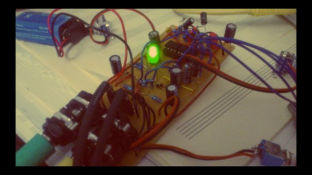
Prototype before being put in the yellow box
When building this thing, you can use both channels of the NE5532 for one channel of audio, gain followed by filter. Note that all connection from the piezo to the first op-amp should be as short as possible, with the possible exception of the shielded cable. In my own build I used 3-pin connectors so I can detach the piezos and attach different ones (see picture below). Mark the + pole!
All in all, this isn’t a difficult build. The configuration of the pots is totally up to you, as long as they are of the logarithmic (or A taper, audio taper) type. If you are building a stereo version, you could use one stereo pot for the filters and two mono pots for separate gains. I also added a LED for showing working status and put everything in a yellow box. If you want a LED, connect it from VCC to VEE through a series resistor (calculate like for example here). You could also use one of those IC prototype PCBs which already have some traces pre-laid, that makes it easier to solder without too many wires.
As usual, use metal film resistors (the blue ones, not the yellow/brown ones) and appropriate film capacitors where non-polarized ones are shown. Happy building!
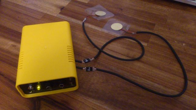
PiezoBanana-1 with detachable piezos

Hello,
Thank you for the interesting article!
I’m really not in circuitry, what do you mean with “When building this thing, you can use both channels of the NE5532 for one channel of audio”.
How can I do this, regarding to your schematics?
Thank you!
LikeLike
Hey Andrea! Well it’s very simple: there are two op-amps in the schematic, U1A an U1B. The NE5532 has two op-amps in one package (on one chip), so you only need one chip for one channel of audio. Hope it helps. Peace!
LikeLike
Hello, Thank you for your article. Really interesting.
I’ve tried to reproduce the circuit with 2 identic model directly from your scheme, but in both cases I have as a result a signal really strong but seems distorted and with a strong hipass (before the filter itself).
I’ve checked all the circuit many times, but I don’t understand what’s wrong…
Maybe do you have some advice or ideas?
Thank you again!
LikeLike
Hey Andrea, it’s hard to tell what’s wrong and I’m not an expert either, but I’d check the power supply first, then check if the diodes are in the right direction, and then most important check if you have correctly connected the GNDREF (which is the virtual earth). GNDREF does not refer to the negative pole of the battery/power supply, so each time you see VEE, it refers to the battery pole, each time you see GNDREF, it’s actually in the middle between + and -, which could be hovering around 4 volts if your battery is at 8 volts, for example.
LikeLiked by 1 person
Thank you ilski, very kind. It took me 2 hours to figure out what was wrong and now I can simply tell that I was forgetting to connect the V+ to the op amp… twice…
Thank you again for the support.
The preamp are really powerful. Really good schematics!
LikeLiked by 1 person
Thank you for providing this informations!
I am curious if it will also work with a DC wall wart 9V instead of the battery?
Do you then need the 9V Battery supply circuit as well or could go go directly from the DC wall wart?
thanks in advance
LikeLike
Hey, sorry for the late reply! Well, I’m not 100% sure but it should work with a wall wart, however, noise might be induced because most power supplies are noisy. You still need the circuit for making a virtual ground and buffering power fluctuations with the caps. Cheers!
LikeLike
Hi! This is just what I need! But, I want to build it with dual rail supply instead of 9v battery, should I just substitute groundref with ground? best regards, Claus Sörensen
LikeLike
Sorry for the late reply! Yes, that would be the way, ground ref would be ground and the new + – would be the two poles.
LikeLike
Hello, nice article! I intend to use this very circuit to match the hi-Z and amplify a passive undersadle acoustic guitar piezo signal. Can I swap the NE5532 to an TL072 opamp? Many Thanks.
LikeLike
Should work in most cases. Try it out, at most you’ll fry the OP-amp 🙂
LikeLike
Thanks, dude! Let´s cook some IC´s.
LikeLike
Hi Ilski, I´m try to use your schem for a guitar undersaddle piezo. As the undersaddle piezo has a considerable bigger signal and I can´t find a 10Kpot with long shaft for my application, I used a RV1 250K pot and a 3K3 R2, thinking in lower the gain a bit. Even with those mods, the gain is way too much. Can you help me with some ideia do tame this little beast? The noise level is fantastic, but I got distortion, even with low volumes. I´ll try to swap the old piezo, but I think that some preamp mods is needed, maybe an input resistor or something. Thank you.
LikeLike
Hey Mauricio! Well, the gain formula being 1 + RV1/R2 making your gain roughly 76-fold with your values. You should try a much higher value for R2, like maybe 25k? Making it roughly 11-fold at max. I’m not sure what gain you need. Try experimenting with those values. Cheers!
LikeLike
Hi there, this is great! Do you have a Veroboard layout for this?
LikeLike
sorry, no, only what you see here
LikeLike