EP1821391A1 - Over-unity energy motor-generator - Google Patents
Over-unity energy motor-generator Download PDFInfo
- Publication number
- EP1821391A1 EP1821391A1 EP07290204A EP07290204A EP1821391A1 EP 1821391 A1 EP1821391 A1 EP 1821391A1 EP 07290204 A EP07290204 A EP 07290204A EP 07290204 A EP07290204 A EP 07290204A EP 1821391 A1 EP1821391 A1 EP 1821391A1
- Authority
- EP
- European Patent Office
- Prior art keywords
- motor
- generator
- unit
- winding
- rotor
- Prior art date
- Legal status (The legal status is an assumption and is not a legal conclusion. Google has not performed a legal analysis and makes no representation as to the accuracy of the status listed.)
- Withdrawn
Links
Images


Classifications
-
- H—ELECTRICITY
- H02—GENERATION; CONVERSION OR DISTRIBUTION OF ELECTRIC POWER
- H02K—DYNAMO-ELECTRIC MACHINES
- H02K47/00—Dynamo-electric converters
- H02K47/12—DC/DC converters
- H02K47/16—Single-armature converters, e.g. metadyne
-
- C—CHEMISTRY; METALLURGY
- C12—BIOCHEMISTRY; BEER; SPIRITS; WINE; VINEGAR; MICROBIOLOGY; ENZYMOLOGY; MUTATION OR GENETIC ENGINEERING
- C12M—APPARATUS FOR ENZYMOLOGY OR MICROBIOLOGY; APPARATUS FOR CULTURING MICROORGANISMS FOR PRODUCING BIOMASS, FOR GROWING CELLS OR FOR OBTAINING FERMENTATION OR METABOLIC PRODUCTS, i.e. BIOREACTORS OR FERMENTERS
- C12M31/00—Means for providing, directing, scattering or concentrating light
- C12M31/10—Means for providing, directing, scattering or concentrating light by light emitting elements located inside the reactor, e.g. LED or OLED
-
- C—CHEMISTRY; METALLURGY
- C12—BIOCHEMISTRY; BEER; SPIRITS; WINE; VINEGAR; MICROBIOLOGY; ENZYMOLOGY; MUTATION OR GENETIC ENGINEERING
- C12M—APPARATUS FOR ENZYMOLOGY OR MICROBIOLOGY; APPARATUS FOR CULTURING MICROORGANISMS FOR PRODUCING BIOMASS, FOR GROWING CELLS OR FOR OBTAINING FERMENTATION OR METABOLIC PRODUCTS, i.e. BIOREACTORS OR FERMENTERS
- C12M41/00—Means for regulation, monitoring, measurement or control, e.g. flow regulation
- C12M41/06—Means for regulation, monitoring, measurement or control, e.g. flow regulation of illumination
-
- H—ELECTRICITY
- H02—GENERATION; CONVERSION OR DISTRIBUTION OF ELECTRIC POWER
- H02K—DYNAMO-ELECTRIC MACHINES
- H02K47/00—Dynamo-electric converters
- H02K47/18—AC/AC converters
-
- H—ELECTRICITY
- H02—GENERATION; CONVERSION OR DISTRIBUTION OF ELECTRIC POWER
- H02P—CONTROL OR REGULATION OF ELECTRIC MOTORS, ELECTRIC GENERATORS OR DYNAMO-ELECTRIC CONVERTERS; CONTROLLING TRANSFORMERS, REACTORS OR CHOKE COILS
- H02P23/00—Arrangements or methods for the control of AC motors characterised by a control method other than vector control
- H02P23/28—Controlling the motor by varying the switching frequency of switches connected to a DC supply and the motor phases
-
- H—ELECTRICITY
- H02—GENERATION; CONVERSION OR DISTRIBUTION OF ELECTRIC POWER
- H02P—CONTROL OR REGULATION OF ELECTRIC MOTORS, ELECTRIC GENERATORS OR DYNAMO-ELECTRIC CONVERTERS; CONTROLLING TRANSFORMERS, REACTORS OR CHOKE COILS
- H02P6/00—Arrangements for controlling synchronous motors or other dynamo-electric motors using electronic commutation dependent on the rotor position; Electronic commutators therefor
- H02P6/08—Arrangements for controlling the speed or torque of a single motor
- H02P6/085—Arrangements for controlling the speed or torque of a single motor in a bridge configuration
-
- H—ELECTRICITY
- H02—GENERATION; CONVERSION OR DISTRIBUTION OF ELECTRIC POWER
- H02P—CONTROL OR REGULATION OF ELECTRIC MOTORS, ELECTRIC GENERATORS OR DYNAMO-ELECTRIC CONVERTERS; CONTROLLING TRANSFORMERS, REACTORS OR CHOKE COILS
- H02P6/00—Arrangements for controlling synchronous motors or other dynamo-electric motors using electronic commutation dependent on the rotor position; Electronic commutators therefor
- H02P6/14—Electronic commutators
-
- H—ELECTRICITY
- H02—GENERATION; CONVERSION OR DISTRIBUTION OF ELECTRIC POWER
- H02P—CONTROL OR REGULATION OF ELECTRIC MOTORS, ELECTRIC GENERATORS OR DYNAMO-ELECTRIC CONVERTERS; CONTROLLING TRANSFORMERS, REACTORS OR CHOKE COILS
- H02P9/00—Arrangements for controlling electric generators for the purpose of obtaining a desired output
- H02P9/007—Control circuits for doubly fed generators
Definitions
- the present invention relates to a motor-generator that can covert an electric energy into a rotational motion and further convert an energy generated by the rotational motion into an electric energy, and more particularly, to a motor-generator using an over-unity brushless direct current (BLDC) motor.
- BLDC brushless direct current
- the BLDC motor uses a hole sensor as a position sensor of a rotor to control a phase of an electric current applied to a stator winding in response to a polarity of the rotor formed of permanent magnets.
- the over-unity BLDC motor is designed to be used as not only a motor but also a generator of the electric vehicle, the efficient use of the energy will be possible.
- the present invention is directed to an over-unity energy motor-generator that can fulfill the above-described need.
- An object of the present invention is to provide an over-unity energy motor-generator that can, when an electric energy is supplied thereto, provide a rotational force by running as a BLDC motor and generate an electric energy using the rotational force.
- an over-unity motor-generator including: a motor circuit unit; a motor-generator unit for generating an electric energy by rotating by an electric energy; and a generator circuit unit for commutating an alternating current generated from the motor-generator unit and outputting a direct current
- the motor-generator unit includes: a stator including a motor winding having n-phases, the motor winding being magnetized by receiving an electric power from the motor circuit unit and wound in an independent, multi-phase parallel distribution manner of an n-phase and a generator winding having 2n-phases and supplying the electric energy to the generator circuit unit, the generator winding being wound in an independent, multi-phase parallel distribution manner; a rotor having stacked silicon plates, flat permanent magnets buried in the stacked silicon plate and arranged in a radial direction, and a shaft located on a center of the stacked silicon plates
- the number of the detection regions of the commutation encoder is determined by the following equation 1
- an angle of the width of the detection regions are determined by the following equation 2
- an arrangement angle of the photo sensors are determined by the following equation 3
- an arrangement angle of the n-phase photo sensor is determined by the following equation 4:
- DN is the number of the detection regions and PN is the number of polarities of the rotor
- PN is the number of polarities of the rotor, the number of phases of the motor, and GP is the number of phases of the generator
- PN is the number of polarities of the rotor
- PN is the number of polarities of the rotor and GP is the number of phases of the generator.
- the stator may further include: flux dividing slots each having a relatively narrow width, the flux dividing slots being formed between motor winding slots and generator winding slots; and cancel eliminating slot each having a relatively narrow width, the cancel eliminating slots being formed between the adjacent generator winding slots.
- the motor generator unit may further include a velocity encoder for detecting rotational velocity of the rotor.
- the motor circuit unit may include: a direct current power supply unit using a direct current power by commutating an alternating current power or is formed of a battery to supply the direct current power; a power switching unit having H-bridges corresponding to the phases, four power semiconductor devices for each phase being connected to the motor winding, two of the semiconductor devices being alternately turned on and off according to a control signal to supply the direct current power to the motor winding; a polarity control unit receiving an optical sensor signal generated by the commutation encoder from the photo sensor and supplying the control signal for establishing the electronic rectifier to the power switching unit; and a PWM (pulse width modulation) control unit for generating a PWM signal for controlling the rotational velocity according to a control signal of a velocity control unit and a command value of a control input unit and transmitting the PWM signal to the power switching unit.
- a direct current power supply unit using a direct current power by commutating an alternating current power or is formed of a battery to supply the direct current power a
- FIG. 1 is a block diagram of an over-unity energy motor-generator according to an embodiment of the present invention
- FIG. 2 is a schematic view of a stator of the over-unity energy motor-generator of FIG. 1;
- FIG. 3 is a view of a stator winding of the over-unity energy motor-generator of FIG. 1;
- FIG. 4 is a schematic view of a rotor of the over-unity energy motor-generator of FIG. 1;
- FIG. 5 is a schematic view of encoders used in the over-unity energy motor-generator of FIG. 1;
- FIG. 6 is a view illustrating a control operation of an over-unity energy motor-generator of FIG. 1;
- FIG. 7 is a view of a signal wave of the over-unity energy motor-generator of FIG. 1.
- FIG. 1 is a block diagram of an over-unity energy motor-generator according to an embodiment of the present invention.
- an over-unity energy motor-generator of this embodiment includes a motor-generator unit 100, a motor circuit unit 200 rotating a rotor of the motor-generator unit 100 such that the motor-generator unit 100 can generate an electric energy, and a generator circuit unit 300 outputting a direct electric current by commutating an alternating electric current generated from the motor-generator unit 100.
- the motor-generator unit 100 includes a main body having a stator 110 (see FIG. 2) and a rotor 120 (see FIG. 4) that are located in a housing 102, and velocity and commutation encoders 130 and 140 that rotate together with a shaft 125 of the main body.
- the motor circuit unit 200 includes a direct current power supply unit 210, a power switching unit 220, a polarity control unit 230, a velocity control unit 240, a control input unit 250, and a pulse width modulation (PWM) control unit 260.
- PWM pulse width modulation
- the direct current power supply unit 210 supplies a direct current power to the power switching unit 220 via a switch 212 by commutating a commercial alternating current power or is formed of a battery to supply the direct current power (V+, V-) to the power switching unit 220 via the switch 212.
- the power switching unit 220 turns a power semiconductor device on and off in response to a control signal to transmit an electric power of the direct current power supply unit 210 to a motor winding M of the stator 110.
- the structure thereof may vary according to the type of the motor (the number of phases of the stator winding).
- four switching elements Q1-Q4 are necessary. Since these four switching element Q1-Q4 are connected to each other in the form of an H-shape, they are called an H-bridge. Therefore, the power switching unit 220 includes a plurality of H-bridges. Transistors, IGBTs, MOSFETs, and FETs are may be used as the switching elements.
- the polarity control unit 230 receives an optical sensor signal from the commutation encoder 140 of the motor generator unit 100 and transmits a control signal for electrically realizing the rectifier to the power switching unit 220 to electrically realize the rectifier.
- the velocity control unit 112 receives an encoder signal from the velocity encoder of the motor generator and transmits a velocity control signal to the PWM control unit 260.
- the control input unit 250 transmits a command signal on the rotational velocity in accordance with the manipulation of a worker.
- the PWM control unit 260 transmits a PWM signal for controlling the rotational velocity of the motor-generator unit 100 according to the control signal to the power switching unit 220.
- the generator circuit unit 300 includes a direct current rectifier 310 commutating the alternating current generated from a generating winding G and outputting the direct current power to the power switching unit 220.
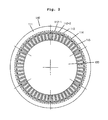
- FIG. 2 is a schematic view of a stator of the over-unity energy motor-generator of FIG. 1
- FIG. 3 is a view of a stator winding of the over-unity energy motor-generator of FIG. 1
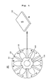
- FIG. 4 is a schematic view of a rotor of the over-unity energy motor-generator of FIG. 1
- FIG. 5 is a schematic view of encoders used in the over-unity energy motor-generator of FIG. 1.
- the motor-generator unit 100 includes the stator 110 placed in the housing 102, the velocity encoder 130 installed at an external side of the housing, and the commutation encoder 140.
- the stator 110 includes a plurality of ring-shaped silicon plates 111 stacked one another, a plurality of winding slots 112-1 and 112-2, a plurality of motor winding slots 113, a plurality of flux divided slots 114, a plurality of cancel elimination slots 115, a plurality of generator winding G wound around the respective generator winding slots 112-1 and 112-2, and a plurality of motor windings M wound around the respective motor winding slots 113.
- the motor windings M functions as a motor rotating the rotor 120 (i.e., motor) by receiving electric power from the motor circuit unit 200.
- the generator windings G functions as a generator generating electric power using the electric current induced by the rotation of the rotor 120.
- the total number of the winding slot and the windings is 54 that are grouped in 6 regions.
- 9 windings M, G, G, M, G, G, M and G i.e., 3 motor windings M and 6 generator windings G are arranged in each region.
- the stator 110 of this embodiment is designed in an independent, multi-phase, and parallel distribution winding structure.
- the number of phases of the motor windings M is 2, 3, 4 ... n.
- the number of phases of the generator windings G is 4, 6, 8 ... 2n.
- the motor windings M are connected to the respective H-bridges of the power switching units 220.
- the generator windings G are connected to the respective direct current rectifiers 310.
- the windings of the respective phases are wound in parallel, as shown in FIG. 3, the windings are distributed and wound by the phase or polarity and connected to respective lead wires without any interconnection.
- stator 110 in the independent, multi-phase parallel distribution structure, a large output can be realized at a low voltage. Since the ratio of the number of the number of the motor windings M to the number of the generator windings G is 1:2, the over-unity efficiency more than 200% can be achieved.
- the flux divided slots 114 each having a relatively narrow width are disposed between the motor winding slots 113 and the generator slots G 112-1 or 112-2, the magnet flux is divided to block a path through which the flux of the motor windings M can flow to the generator windings G so that the flux of the motor windings M can flow only to the magnetic field of the stator 110, thereby allowing the motor to effectively drive.
- the flux divide slot 114 maintains constantly the exciting width around the motor winding slot 113 so that the motor winding slots 113 can operate without affecting or being affected by the adjacent winding slots during driving or alternation.
- the cancel elimination slots 115 each having a relatively narrow width are disposed between the generator windings 112-1 and the adjacent generator slots 112-1 to eliminate the flux cancel, thereby improving the generation efficiency.
- the rotor 120 of the motor-generator unit includes a plurality of silicon plates 121 stacked one another and a plurality of flat permanent magnets 122 buried in the stacked silicon plates 121 in a radial direction.
- the permanent magnets 122 are designed having a strong magnetic force such that a relative wide magnetic field surface can be formed and thus the magnetic flux can be concentrated on the magnetic filed surface, thereby increasing the magnetic flux density of the magnetic field surface.
- the number of polarities of the rotor 120 is set in response to the number of the polarities of the stator 110.
- each permanent magnet 122 is equally spaced apart from each other and buried in the stacked circular silicon plates 121.
- a non-magnet core 124 is placed on a center of the stacked circular silicon plates 121 to support the permanent magnets 122 and the silicon plates 121 and a shaft 125 is disposed through the center of the nonmagnetic core 124.
- the permanent magnets 122 are formed in a flat-shape and empty spaces are formed between the permanent magnets 122.
- the motor using the permanent magnets is designed having a rotational force formed by the combination of the passive energy of the rotor 120 and the active energy of the stator 110.
- the passive energy of the rotor 120 In order to the over-unity energy in the motor, it is important to enhance the passive energy of the rotor 120. Therefore, "Neodymium(Nd,Fe,B)" magnets are used in this embodiment. These magnets enlarge the magnetic field surface and allows the magnetic flux to be concentrated on the magnetic field of the rotor, thereby enhancing the magnetic flux density of the magnetic field.
- the commutation encoder 140 and the velocity encoder 130 are provided to control the rotation of the motor-generator unit 100. As shown in FIG. 5, the commutation encoder 140 and the velocity encoder 130 are installed on an outer depressed portion of the motor main body housing to rotate together with the rotational shaft 125 of the rotor 120.
- the velocity encoder 130 is a cup-shaped encoder having protrusions uniformly spaced apart from each other.
- the velocity encoder 130 is operated together with a photo sensor 152 installed on a sensor mount plate 150 to generate the velocity signal.
- the commutation encoder 140 is also a cup-shaped encoder having detecting and non-detection regions 144 and 142.
- the commutation encoder 140 is operated together with a photo senor installed on the sensor mount plate 150 to generator an optical sensor signal for realizing the electronic rectifier.
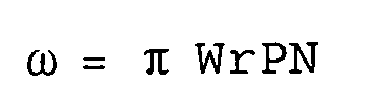
- the number of detection regions 144 of the communication encoder 140 is determined according to the following equation 1 and an angle ⁇ of a width of the detection region is determined according to the following equation 2.
- DN is the number of the detection regions and PN is the number of polarities of the rotor.
- Equation 2 ⁇ WrPN MP + GP s MP + GP - 1
- PN is the number of polarities of the rotor, the number of phases of the motor, and GP is the number of phases of the generator.
- two photo sensors (first and second photo sensors) 154 per one phase are arranged so that they can be operated together with the commutation encoder 140.
- the arrangement angle ⁇ of the first and second photo sensors 154 is determined according to the following equation 3.
- PN is the number of polarities of the rotor.
- the arrangement angle ⁇ n of 2n-photosensor 154 can be determined according to the following equation 4.
- PN is the number of polarities of the rotor and GP is the number of phases of the generator.
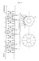
- FIG. 6 is a view illustrating a control operation of an over-unity energy motor-generator of FIG. 1
- FIG. 7 is a view of a signal wave of the over-unity energy motor-generator of FIG. 1.
- the two photo sensors 154 of each phase is connected to switching elements of a half switch of the H-bridges of the corresponding phase to realize the electronic rectifier.
- the photo sensor located on the detection regions 144 of the commutation encoder turns on the half bridge of the corresponding phase of the electronic rectifier to determine the rotational direction of the rotor and the drive the motor.
- an exciting width modulation is realized by the width of the detection regions 144 to turn on or off the half bridge to determine the on/off period according to which the half bridge is alternately turn on and off to effectively drive the motor-generator unit 100.
- the voltage of the motor-generator unit 260 varies so that the motor-generator unit 260 can operate at a constant velocity, thereby maintaining the predetermined require voltage.
- the direct current powers V+ and V- inputted from the motor circuit unit 200 are connected to the H-bridges of the phases A, B and C to supply electric power to the motor windings M of the respective phases.
- the H-bridges of the phases R, S and T and the H-bridges of the phases U, V and W commutate the corresponding electric powers generated by the generator windings G of the respective phases using the corresponding diode rectifiers and output the direct current voltage.
- the transistors Q1 through Q4 form the H-bridge for the phase A.
- the transistor Q1 and a base of the transistor Q3 are connected to the second photo sensor PA2.
- the transistors Q2 through Q8 form the H-bridge for the phase B.
- the transistor Q5 and a base of the transistor Q7 are connected to the first photo sensor PB1.
- the transistor Q6 and a base of the transistor Q8 are connected to the second photo sensor PB2.
- the transistors Q9 through Q12 form the H-bridge for the phase C.
- the transistor Q9 and a base of the transistor Q11 are connected to the first photo sensor PC1 and the transistor Q10 and a base of the transistor Q12 are connected to the second photo sensor PC2.
- the transistor Q1 is turned on while the transistor Q3 is turned off. Since the second photo sensor PA2 of the phase A is located on the non-detection region 142 of the commutation encoder, the transistor Q2 is turned off while the transistor Q4 is turned on to allow the current to flow from the transistor Q1 to the transistor Q4 via the motor winding M.
- the transistor Q5 Since the first photo sensor PB1 of the phase B is located on the detection region 144 of the commutation encoder, the transistor Q5 is turned on while the transistor Q 7 is turned off. Since the second photo sensor PB2 of the phase B is located on the non-detection region 142 of the commutation encoder, the transistor Q6 is turned off while the transistor Q8 is turned on to allow the current to flow from the transistor Q5 to the transistor Q8 via the motor winding M.
- both the first and second photo sensors PA1 and PA2 are located on the non-detection regions, no electric current is applied.
- the transistors Q2 and Q3 are turned on to allow the current to flow from the transistor Q2 to the transistor Q3 via the motor winding M.
- the flow direction of the current flowing along the motor winding M is opposite to that when the first photo sensor PA1 is located on the detection region.
- FIG. 7 shows torque scheme waves of the phases A, B and C throughout a rotational angle range of 0-360° of the shaft of the motor-generator, a total torque scheme of the torque scheme waves (A+B+C) throughout the rotational angle range of 0-360°, and current waves of the phases R, S and T and current waves of the phases U, V and W throughout the rotational angle range of 0-360°.
- PA1 and PA2 show an on/off wave of the photo sensor of the phase A
- PB1 and PB2 show an on/off wave of the photo sensor of the phase B
- PC1 and PC2 show an on/off wave of the photo sensor of the phase C.
- the energy can be effectively used.
- the ratio of the motor winding to the generator winding is 1:2, the over-unity energy motor-generator can be realized.
Abstract
An over-unity motor-generator is provided. The over-unity motor-generator includes a motor circuit unit, a motor-generator unit for generating an electric energy by rotating by an electric energy, and a generator circuit unit for commutating an alternating current generated from the motor-generator unit and outputting a direct current. The motor-generator unit includes a stator including a motor winding having n-phases, the motor winding being magnetized by receiving an electric power from the motor circuit unit and wound in an independent, multi-phase parallel distribution manner of an n-phase and a generator winding having 2n-phases and supplying the electric energy to the generator circuit unit, the generator winding being wound in an independent, multi-phase parallel distribution manner, a rotor having stacked silicon plates, flat permanent magnets buried in the stacked silicon plate and arranged in a radial direction, and a shaft located on a center of the stacked silicon plates, a commutation encoder having detection regions and non-detection regions and disposed on an end of the shaft of the rotor, and 2n-number photo sensors for transmitting an optical sensor signal to the motor circuit unit by, when the commutation encoder rotates together with the shaft, being turned on at the detection regions and off at the non-detection regions.
Description
- The present invention relates to a motor-generator that can covert an electric energy into a rotational motion and further convert an energy generated by the rotational motion into an electric energy, and more particularly, to a motor-generator using an over-unity brushless direct current (BLDC) motor.
- Likewise a direct current motor having a brush, since a BLDC motor also does not have a mechanical contact point, no noise is generated and thus the service life thereof increases. Therefore, the BLDC motor is widely used in a variety of fields such as industrial machines, home appliance, transportation, and the like. The BLDC motor uses a hole sensor as a position sensor of a rotor to control a phase of an electric current applied to a stator winding in response to a polarity of the rotor formed of permanent magnets.
- Recently, considering the exhaust of petroleum resources and environmental pollution problem, endeavors for finding out a clean energy have been done. Especially, in an automobile field causing the major environment pollution problem, an electric vehicle has been developed.
- Therefore, when the over-unity BLDC motor is designed to be used as not only a motor but also a generator of the electric vehicle, the efficient use of the energy will be possible.
- Accordingly, the present invention is directed to an over-unity energy motor-generator that can fulfill the above-described need.
- An object of the present invention is to provide an over-unity energy motor-generator that can, when an electric energy is supplied thereto, provide a rotational force by running as a BLDC motor and generate an electric energy using the rotational force.
- Additional advantages, objects, and features of the invention will be set forth in part in the description which follows and in part will become apparent to those having ordinary skill in the art upon examination of the following or may be learned from practice of the invention. The objectives and other advantages of the invention may be realized and attained by the structure particularly pointed out in the written description and claims hereof as well as the appended drawings.
- To achieve these objects and other advantages and in accordance with the purpose of the invention, as embodied and broadly described herein, there is provided an over-unity motor-generator including: a motor circuit unit; a motor-generator unit for generating an electric energy by rotating by an electric energy; and a generator circuit unit for commutating an alternating current generated from the motor-generator unit and outputting a direct current, wherein the motor-generator unit includes: a stator including a motor winding having n-phases, the motor winding being magnetized by receiving an electric power from the motor circuit unit and wound in an independent, multi-phase parallel distribution manner of an n-phase and a generator winding having 2n-phases and supplying the electric energy to the generator circuit unit, the generator winding being wound in an independent, multi-phase parallel distribution manner; a rotor having stacked silicon plates, flat permanent magnets buried in the stacked silicon plate and arranged in a radial direction, and a shaft located on a center of the stacked silicon plates; a commutation encoder having detection regions and non-detection regions and disposed on an end of the shaft of the rotor; and 2n-number photo sensors for transmitting an optical sensor signal to the motor circuit unit by, when the commutation encoder rotates together with the shaft, being turned on at the detection regions and off at the non-detection regions.
- The number of the detection regions of the commutation encoder is determined by the following
equation 1, an angle of the width of the detection regions are determined by the following equation 2, an arrangement angle of the photo sensors are determined by the following equation 3, and an arrangement angle of the n-phase photo sensor is determined by the following equation 4: -

- where, DN is the number of the detection regions and PN is the number of polarities of the rotor,
-

- where, PN is the number of polarities of the rotor, the number of phases of the motor, and GP is the number of phases of the generator,
-

- where, PN is the number of polarities of the rotor, and
-

- where, PN is the number of polarities of the rotor and GP is the number of phases of the generator.
- The stator may further include: flux dividing slots each having a relatively narrow width, the flux dividing slots being formed between motor winding slots and generator winding slots; and cancel eliminating slot each having a relatively narrow width, the cancel eliminating slots being formed between the adjacent generator winding slots.
- The motor generator unit may further include a velocity encoder for detecting rotational velocity of the rotor.
- The motor circuit unit may include: a direct current power supply unit using a direct current power by commutating an alternating current power or is formed of a battery to supply the direct current power; a power switching unit having H-bridges corresponding to the phases, four power semiconductor devices for each phase being connected to the motor winding, two of the semiconductor devices being alternately turned on and off according to a control signal to supply the direct current power to the motor winding; a polarity control unit receiving an optical sensor signal generated by the commutation encoder from the photo sensor and supplying the control signal for establishing the electronic rectifier to the power switching unit; and a PWM (pulse width modulation) control unit for generating a PWM signal for controlling the rotational velocity according to a control signal of a velocity control unit and a command value of a control input unit and transmitting the PWM signal to the power switching unit.
- It is to be understood that both the foregoing general description and the following detailed description of the present invention are exemplary and explanatory and are intended to provide further explanation of the invention as claimed.
- The accompanying drawings, which are included to provide a further understanding of the invention and are incorporated in and constitute a part of this application, illustrate embodiment(s) of the invention and together with the description serve to explain the principle of the invention. In the drawings:
- FIG. 1 is a block diagram of an over-unity energy motor-generator according to an embodiment of the present invention;
- FIG. 2 is a schematic view of a stator of the over-unity energy motor-generator of FIG. 1;
- FIG. 3 is a view of a stator winding of the over-unity energy motor-generator of FIG. 1;
- FIG. 4 is a schematic view of a rotor of the over-unity energy motor-generator of FIG. 1;
- FIG. 5 is a schematic view of encoders used in the over-unity energy motor-generator of FIG. 1;
- FIG. 6 is a view illustrating a control operation of an over-unity energy motor-generator of FIG. 1; and
- FIG. 7 is a view of a signal wave of the over-unity energy motor-generator of FIG. 1.
- Reference will now be made in detail to the preferred embodiments of the present invention, examples of which are illustrated in the accompanying drawings. Wherever possible, the same reference numbers will be used throughout the drawings to refer to the same or like parts.
- FIG. 1 is a block diagram of an over-unity energy motor-generator according to an embodiment of the present invention.
- Referring to FIG. 1, an over-unity energy motor-generator of this embodiment includes a motor-
generator unit 100, amotor circuit unit 200 rotating a rotor of the motor-generator unit 100 such that the motor-generator unit 100 can generate an electric energy, and agenerator circuit unit 300 outputting a direct electric current by commutating an alternating electric current generated from the motor-generator unit 100. - The motor-
generator unit 100 includes a main body having a stator 110 (see FIG. 2) and a rotor 120 (see FIG. 4) that are located in ahousing 102, and velocity andcommutation encoders shaft 125 of the main body. - The
motor circuit unit 200 includes a direct currentpower supply unit 210, apower switching unit 220, apolarity control unit 230, avelocity control unit 240, acontrol input unit 250, and a pulse width modulation (PWM)control unit 260. - The direct current
power supply unit 210 supplies a direct current power to thepower switching unit 220 via aswitch 212 by commutating a commercial alternating current power or is formed of a battery to supply the direct current power (V+, V-) to thepower switching unit 220 via theswitch 212. - The
power switching unit 220 turns a power semiconductor device on and off in response to a control signal to transmit an electric power of the direct currentpower supply unit 210 to a motor winding M of thestator 110. Here, since thepower switching unit 220 is provided to supply the direct current power to the motor winding M of thestator 110, the structure thereof may vary according to the type of the motor (the number of phases of the stator winding). In order to driving one phase, four switching elements Q1-Q4 are necessary. Since these four switching element Q1-Q4 are connected to each other in the form of an H-shape, they are called an H-bridge. Therefore, thepower switching unit 220 includes a plurality of H-bridges. Transistors, IGBTs, MOSFETs, and FETs are may be used as the switching elements. - The
polarity control unit 230 receives an optical sensor signal from thecommutation encoder 140 of themotor generator unit 100 and transmits a control signal for electrically realizing the rectifier to thepower switching unit 220 to electrically realize the rectifier. The velocity control unit 112 receives an encoder signal from the velocity encoder of the motor generator and transmits a velocity control signal to thePWM control unit 260. - The
control input unit 250 transmits a command signal on the rotational velocity in accordance with the manipulation of a worker. ThePWM control unit 260 transmits a PWM signal for controlling the rotational velocity of the motor-generator unit 100 according to the control signal to thepower switching unit 220. - The
generator circuit unit 300 includes adirect current rectifier 310 commutating the alternating current generated from a generating winding G and outputting the direct current power to thepower switching unit 220. - FIG. 2 is a schematic view of a stator of the over-unity energy motor-generator of FIG. 1, FIG. 3 is a view of a stator winding of the over-unity energy motor-generator of FIG. 1, FIG. 4 is a schematic view of a rotor of the over-unity energy motor-generator of FIG. 1, and FIG. 5 is a schematic view of encoders used in the over-unity energy motor-generator of FIG. 1.
- The motor-
generator unit 100 includes thestator 110 placed in thehousing 102, thevelocity encoder 130 installed at an external side of the housing, and thecommutation encoder 140. - As shown in FIG. 2, the
stator 110 includes a plurality of ring-shaped silicon plates 111 stacked one another, a plurality of winding slots 112-1 and 112-2, a plurality ofmotor winding slots 113, a plurality of flux dividedslots 114, a plurality of cancelelimination slots 115, a plurality of generator winding G wound around the respective generator winding slots 112-1 and 112-2, and a plurality of motor windings M wound around the respectivemotor winding slots 113. - The motor windings M functions as a motor rotating the rotor 120 (i.e., motor) by receiving electric power from the
motor circuit unit 200. The generator windings G functions as a generator generating electric power using the electric current induced by the rotation of therotor 120. - In this embodiment, the total number of the winding slot and the windings is 54 that are grouped in 6 regions. 9 windings M, G, G, M, G, G, M and G (i.e., 3 motor windings M and 6 generator windings G) are arranged in each region.
- Referring again to FIG. 2, the
stator 110 of this embodiment is designed in an independent, multi-phase, and parallel distribution winding structure. At this point, the number of phases of the motor windings M is 2, 3, 4 ... n. The number of phases of the generator windings G is 4, 6, 8 ... 2n. The motor windings M are connected to the respective H-bridges of thepower switching units 220. The generator windings G are connected to the respective directcurrent rectifiers 310. - When the windings of the respective phases are wound in parallel, as shown in FIG. 3, the windings are distributed and wound by the phase or polarity and connected to respective lead wires without any interconnection.
- As described above, by forming the
stator 110 in the independent, multi-phase parallel distribution structure, a large output can be realized at a low voltage. Since the ratio of the number of the number of the motor windings M to the number of the generator windings G is 1:2, the over-unity efficiency more than 200% can be achieved. - In addition, since the flux divided
slots 114 each having a relatively narrow width are disposed between themotor winding slots 113 and the generator slots G 112-1 or 112-2, the magnet flux is divided to block a path through which the flux of the motor windings M can flow to the generator windings G so that the flux of the motor windings M can flow only to the magnetic field of thestator 110, thereby allowing the motor to effectively drive. In addition, theflux divide slot 114 maintains constantly the exciting width around themotor winding slot 113 so that themotor winding slots 113 can operate without affecting or being affected by the adjacent winding slots during driving or alternation. - The cancel
elimination slots 115 each having a relatively narrow width are disposed between the generator windings 112-1 and the adjacent generator slots 112-1 to eliminate the flux cancel, thereby improving the generation efficiency. - Referring to FIG. 4, the
rotor 120 of the motor-generator unit includes a plurality ofsilicon plates 121 stacked one another and a plurality of flatpermanent magnets 122 buried in the stackedsilicon plates 121 in a radial direction. At this point, thepermanent magnets 122 are designed having a strong magnetic force such that a relative wide magnetic field surface can be formed and thus the magnetic flux can be concentrated on the magnetic filed surface, thereby increasing the magnetic flux density of the magnetic field surface. The number of polarities of therotor 120 is set in response to the number of the polarities of thestator 110. - Describing the
rotor 120 in more detail, sixpermanent magnets 122 are equally spaced apart from each other and buried in the stackedcircular silicon plates 121. Anon-magnet core 124 is placed on a center of the stackedcircular silicon plates 121 to support thepermanent magnets 122 and thesilicon plates 121 and ashaft 125 is disposed through the center of thenonmagnetic core 124. Thepermanent magnets 122 are formed in a flat-shape and empty spaces are formed between thepermanent magnets 122. - The motor using the permanent magnets is designed having a rotational force formed by the combination of the passive energy of the
rotor 120 and the active energy of thestator 110. In order to the over-unity energy in the motor, it is important to enhance the passive energy of therotor 120. Therefore, "Neodymium(Nd,Fe,B)" magnets are used in this embodiment. These magnets enlarge the magnetic field surface and allows the magnetic flux to be concentrated on the magnetic field of the rotor, thereby enhancing the magnetic flux density of the magnetic field. - Meanwhile, the
commutation encoder 140 and thevelocity encoder 130 are provided to control the rotation of the motor-generator unit 100. As shown in FIG. 5, thecommutation encoder 140 and thevelocity encoder 130 are installed on an outer depressed portion of the motor main body housing to rotate together with therotational shaft 125 of therotor 120. - Referring to FIG. 5, the
velocity encoder 130 is a cup-shaped encoder having protrusions uniformly spaced apart from each other. Thevelocity encoder 130 is operated together with aphoto sensor 152 installed on asensor mount plate 150 to generate the velocity signal. Thecommutation encoder 140 is also a cup-shaped encoder having detecting andnon-detection regions commutation encoder 140 is operated together with a photo senor installed on thesensor mount plate 150 to generator an optical sensor signal for realizing the electronic rectifier. - The number of
detection regions 144 of thecommunication encoder 140 is determined according to thefollowing equation 1 and an angle θ of a width of the detection region is determined according to the following equation 2. -

- where, DN is the number of the detection regions and PN is the number of polarities of the rotor.
-

- where, PN is the number of polarities of the rotor, the number of phases of the motor, and GP is the number of phases of the generator.
- In addition, two photo sensors (first and second photo sensors) 154 per one phase are arranged so that they can be operated together with the
commutation encoder 140. At this point, the arrangement angle ω of the first andsecond photo sensors 154 is determined according to the following equation 3. -

-
- where, PN is the number of polarities of the rotor.
- Therefore, in the motor having n-phase, the arrangement angle ωn of 2n-
photosensor 154 can be determined according to the following equation 4. -

- Where, PN is the number of polarities of the rotor and GP is the number of phases of the generator.
- FIG. 6 is a view illustrating a control operation of an over-unity energy motor-generator of FIG. 1 and FIG. 7 is a view of a signal wave of the over-unity energy motor-generator of FIG. 1.
- As shown in FIG. 6, the two
photo sensors 154 of each phase is connected to switching elements of a half switch of the H-bridges of the corresponding phase to realize the electronic rectifier. At this point, the photo sensor located on thedetection regions 144 of the commutation encoder turns on the half bridge of the corresponding phase of the electronic rectifier to determine the rotational direction of the rotor and the drive the motor. When the rotor rotates, an exciting width modulation is realized by the width of thedetection regions 144 to turn on or off the half bridge to determine the on/off period according to which the half bridge is alternately turn on and off to effectively drive the motor-generator unit 100. In addition, when the velocity of the motor-generator unit 100 increases or decreases through the PWM control according to the control signal of thePWM control unit 260, the voltage of the motor-generator unit 260 varies so that the motor-generator unit 260 can operate at a constant velocity, thereby maintaining the predetermined require voltage. - For example, referring to FIG. 6, the direct current powers V+ and V- inputted from the
motor circuit unit 200 are connected to the H-bridges of the phases A, B and C to supply electric power to the motor windings M of the respective phases. The H-bridges of the phases R, S and T and the H-bridges of the phases U, V and W commutate the corresponding electric powers generated by the generator windings G of the respective phases using the corresponding diode rectifiers and output the direct current voltage. - Describing the H-bridges of the phases A, B and C, which operate as the motor, the transistors Q1 through Q4 form the H-bridge for the phase A. The transistor Q1 and a base of the transistor Q3 are connected to the second photo sensor PA2. the transistors Q2 through Q8 form the H-bridge for the phase B. the transistor Q5 and a base of the transistor Q7 are connected to the first photo sensor PB1. The transistor Q6 and a base of the transistor Q8 are connected to the second photo sensor PB2. In addition, the transistors Q9 through Q12 form the H-bridge for the phase C. The transistor Q9 and a base of the transistor Q11 are connected to the first photo sensor PC1 and the transistor Q10 and a base of the transistor Q12 are connected to the second photo sensor PC2.
- In the above-described connection state, the operation when, as shown in FIG. 6, the first photo sensor PA1 of the phase A and the first photo sensor PB1 of the phase B are located on the
detection regions 144 of thecommutation encoder 140 and the rest photo sensors PC1, PA2, PB2, and PC2 are located on thenon-detection regions 142 will be described hereinafter. - First, since the first photo sensor PA1 of the phase A is located on the
detection region 144 of the commutation encoder, the transistor Q1 is turned on while the transistor Q3 is turned off. Since the second photo sensor PA2 of the phase A is located on thenon-detection region 142 of the commutation encoder, the transistor Q2 is turned off while the transistor Q4 is turned on to allow the current to flow from the transistor Q1 to the transistor Q4 via the motor winding M. - Since the first photo sensor PB1 of the phase B is located on the
detection region 144 of the commutation encoder, the transistor Q5 is turned on while the transistor Q 7 is turned off. Since the second photo sensor PB2 of the phase B is located on thenon-detection region 142 of the commutation encoder, the transistor Q6 is turned off while the transistor Q8 is turned on to allow the current to flow from the transistor Q5 to the transistor Q8 via the motor winding M. - If both the first and second photo sensors PA1 and PA2 are located on the non-detection regions, no electric current is applied. When the second photo sensor PA2 is located on the detection region, the transistors Q2 and Q3 are turned on to allow the current to flow from the transistor Q2 to the transistor Q3 via the motor winding M. At this point, it can be noted that the flow direction of the current flowing along the motor winding M is opposite to that when the first photo sensor PA1 is located on the detection region.
- Again, when the first and second photo sensors PA1 and PA2 are located on the
non-detection regions 142, no electric current is applied again. These processes are repeated to realize the alternating electric current application. At this point, the phases A, B and C undergo the alternating phase-shift-excitation to effectively drive the motor-generator unit 100. Therefore, a trapezoidal current is generated from the generator winding G such that the electric power whose voltage increases or decreases in accordance with the rotation velocity is outputted. - FIG. 7 shows torque scheme waves of the phases A, B and C throughout a rotational angle range of 0-360° of the shaft of the motor-generator, a total torque scheme of the torque scheme waves (A+B+C) throughout the rotational angle range of 0-360°, and current waves of the phases R, S and T and current waves of the phases U, V and W throughout the rotational angle range of 0-360°.
- In FIG. 7, PA1 and PA2 show an on/off wave of the photo sensor of the phase A, PB1 and PB2 show an on/off wave of the photo sensor of the phase B, and PC1 and PC2 show an on/off wave of the photo sensor of the phase C.
- According to the present invention, since the motor and the generator are integrated, the energy can be effectively used. Particularly, since the ratio of the motor winding to the generator winding is 1:2, the over-unity energy motor-generator can be realized.
- It will be apparent to those skilled in the art that various modifications and variations can be made in the present invention. Thus, it is intended that the present invention covers the modifications and variations of this invention provided they come within the scope of the appended claims and their equivalents.
Claims (5)
- An over-unity motor-generator comprising:a motor circuit unit;a motor-generator unit for generating an electric energy by rotating by an electric energy; anda generator circuit unit for commutating an alternating current generated from the motor-generator unit and outputting a direct current,wherein the motor-generator unit comprises:a stator including a motor winding having n-phases, the motor winding being magnetized by receiving an electric power from the motor circuit unit and wound in an independent, multi-phase parallel distribution manner of an n-phase and a generator winding having 2n-phases and supplying the electric energy to the generator circuit unit, the generator winding being wound in an independent, multi-phase parallel distribution manner;a rotor having stacked silicon plates, flat permanent magnets buried in the stacked silicon plate and arranged in a radial direction, and a shaft located on a center of the stacked silicon plates;a commutation encoder having detection regions and non-detection regions and disposed on an end of the shaft of the rotor; and2n-number photo sensors for transmitting an optical sensor signal to the motor circuit unit by, when the commutation encoder rotates together with the shaft, being turned on at the detection regions and off at the non-detection regions.
- The over-unity motor-generator of claim 1, wherein the number of the detection regions of the commutation encoder is determined by the following equation 1, an angle of the width of the detection regions are determined by the following equation 2, an arrangement angle of the photo sensors are determined by the following equation 3, and an arrangement angle of the n-phase photo sensor is determined by the following equation 4:

where, DN is the number of the detection regions and PN is the number of polarities of the rotor,
where, PN is the number of polarities of the rotor, the number of phases of the motor, and GP is the number of phases of the generator,
where, PN is the number of polarities of the rotor, and

where, PN is the number of polarities of the rotor and GP is the number of phases of the generator. - The over-unity motor-generator of claim 1, wherein the stator further includes:flux dividing slots each having a relatively narrow width, the flux dividing slots being formed between motor winding slots and generator winding slots; andcancel eliminating slot each having a relatively narrow width, the cancel eliminating slots being formed between the adjacent generator winding slots.
- The over-unity motor generator of claim 1, wherein the motor generator unit further comprises a velocity encoder for detecting rotational velocity of the rotor.
- The over-unity motor generator of claim 1, wherein the motor circuit unit comprises:a direct current power supply unit using a direct current power by commutating an alternating current power or is formed of a battery to supply the direct current power;a power switching unit having H-bridges corresponding to the phases, four power semiconductor devices for each phase being connected to the motor winding, two of the semiconductor devices being alternately turned on and off according to a control signal to supply the direct current power to the motor winding;a polarity control unit receiving an optical sensor signal generated by the commutation encoder from the photo sensor and supplying the control signal for establishing the electronic rectifier to the power switching unit; anda PWM (pulse width modulation) control unit for generating a PWM signal for controlling the rotational velocity according to a control signal of a velocity control unit and a command value of a control input unit and transmitting the PWM signal to the power switching unit.
Applications Claiming Priority (1)
| Application Number | Priority Date | Filing Date | Title |
|---|---|---|---|
| KR1020060015915A KR20070082819A (en) | 2006-02-18 | 2006-02-18 | High efficient motor-generator |
Publications (1)
| Publication Number | Publication Date |
|---|---|
| EP1821391A1 true EP1821391A1 (en) | 2007-08-22 |
Family
ID=37986787
Family Applications (1)
| Application Number | Title | Priority Date | Filing Date |
|---|---|---|---|
| EP07290204A Withdrawn EP1821391A1 (en) | 2006-02-18 | 2007-02-16 | Over-unity energy motor-generator |
Country Status (15)
| Country | Link |
|---|---|
| US (1) | US20070210730A1 (en) |
| EP (1) | EP1821391A1 (en) |
| JP (1) | JP2007221995A (en) |
| KR (1) | KR20070082819A (en) |
| CN (1) | CN101026329A (en) |
| AR (1) | AR059528A1 (en) |
| AU (1) | AU2007200624A1 (en) |
| BR (1) | BRPI0701382A2 (en) |
| CA (1) | CA2578658A1 (en) |
| CL (1) | CL2007000406A1 (en) |
| MX (1) | MX2007001881A (en) |
| PE (1) | PE20071272A1 (en) |
| RU (1) | RU2007105765A (en) |
| SG (1) | SG135108A1 (en) |
| TW (1) | TW200737656A (en) |
Cited By (1)
| Publication number | Priority date | Publication date | Assignee | Title |
|---|---|---|---|---|
| WO2010054608A1 (en) * | 2008-09-12 | 2010-05-20 | Getriebetechnik Kassel Schäfer Gmbh | Annular power converter having a motive effect |
Families Citing this family (24)
| Publication number | Priority date | Publication date | Assignee | Title |
|---|---|---|---|---|
| KR100815429B1 (en) * | 2005-12-14 | 2008-03-20 | 이옥재 | A constant-power brushless DC motor and the generator thereby |
| KR100934773B1 (en) * | 2008-06-03 | 2009-12-30 | 유동식 | Power generator using electromagnet |
| US20110241630A1 (en) | 2008-09-03 | 2011-10-06 | Exro Technologies Inc. | Power conversion system for a multi-stage generator |
| AT507320B1 (en) * | 2008-10-02 | 2010-10-15 | Hoerbiger Kompressortech Hold | RECIPROCATING COMPRESSOR |
| JP2010115068A (en) * | 2008-11-10 | 2010-05-20 | Hitachi Ltd | Motor and motor control device |
| BR112012004808A2 (en) * | 2009-09-03 | 2018-03-13 | Exro Tech Inc | variable coil configuration system, apparatus and method |
| JP4441584B1 (en) * | 2009-09-04 | 2010-03-31 | 敏雄 合田 | Back electromotive force generator motor |
| CN102025242A (en) * | 2011-01-07 | 2011-04-20 | 南昌康富电机技术有限公司 | Single-armature electric harmonic excitation six-phase synchronous generator |
| DE102011084627A1 (en) * | 2011-10-17 | 2013-04-18 | Dunkermotoren Gmbh | Electric motor with a rotary encoder |
| KR20150048507A (en) * | 2013-10-28 | 2015-05-07 | 이이수 | Induced Polarization Brushless DC Electric Motor |
| CN104065229A (en) * | 2014-06-10 | 2014-09-24 | 华中科技大学 | Electric power generation integration inductor motor |
| KR20160077974A (en) * | 2014-12-24 | 2016-07-04 | 이이수 | Induced Polarization AC Motor |
| CN104601078B (en) * | 2014-12-25 | 2017-10-17 | 国网浙江省电力公司嵊泗县供电公司 | A kind of control method of power system multi-function motor |
| CN104579087B (en) * | 2014-12-25 | 2017-08-15 | 贵州标准电机有限公司 | A kind of motor control method of low-cost environmental-protecting |
| KR102099409B1 (en) * | 2015-06-26 | 2020-04-09 | 이이수 | Induced polarization switching-less dc motor |
| CN107994814A (en) * | 2015-12-02 | 2018-05-04 | 刘振韬 | Multi-phase brushless DC motor and its driving method |
| US11081996B2 (en) | 2017-05-23 | 2021-08-03 | Dpm Technologies Inc. | Variable coil configuration system control, apparatus and method |
| JP2020524968A (en) * | 2017-06-22 | 2020-08-20 | チェ ヒョン クJei Hyun Goo | A device that rotates a shaft using one electromagnet |
| CN107346932A (en) * | 2017-07-31 | 2017-11-14 | 重庆宙盾新能源技术开发有限公司 | A kind of magnetic-energy generator |
| CN108616204A (en) * | 2018-06-29 | 2018-10-02 | 陈雷 | Electric-driving generation integrating machine |
| WO2020150747A1 (en) | 2019-01-20 | 2020-07-23 | Airborne Motors, Llc | Medical stabilizer harness method and apparatus |
| EP3942679A4 (en) * | 2019-03-19 | 2022-12-14 | Airborne Motors, LLC | Electric circulatory leverage drive method and apparatus |
| US11722026B2 (en) | 2019-04-23 | 2023-08-08 | Dpm Technologies Inc. | Fault tolerant rotating electric machine |
| US11897362B2 (en) | 2021-05-04 | 2024-02-13 | Exro Technologies Inc. | Systems and methods for individual control of a plurality of controllable units of battery cells |
Citations (3)
| Publication number | Priority date | Publication date | Assignee | Title |
|---|---|---|---|---|
| US4743828A (en) * | 1981-09-02 | 1988-05-10 | Gould Inc. | Electric drive system |
| EP1130757A1 (en) * | 1998-09-25 | 2001-09-05 | Fumito Komatsu | Synchronous motor |
| EP1503485A1 (en) * | 2003-08-01 | 2005-02-02 | Nissan Motor Company, Limited | Rotating machine |
Family Cites Families (5)
| Publication number | Priority date | Publication date | Assignee | Title |
|---|---|---|---|---|
| JPS522013Y2 (en) * | 1972-03-22 | 1977-01-18 | ||
| RU2221323C2 (en) * | 1995-08-16 | 2004-01-10 | Йоун Соо БАЕ | Magnetic circuits in revolving system for generating both mechanical and electrical energy |
| KR19990013313A (en) * | 1998-02-11 | 1999-02-25 | 이이수 | Variable Voltage Outputless Rectifier DC Motor |
| US6359401B1 (en) * | 2000-10-16 | 2002-03-19 | Neil Garcia-Sinclair | Multi-phase bipolar brushless D.C. motor |
| KR20030015098A (en) * | 2001-08-14 | 2003-02-20 | 박병순 | Ultra low voltage alternator |
-
2006
- 2006-02-18 KR KR1020060015915A patent/KR20070082819A/en not_active Application Discontinuation
-
2007
- 2007-02-05 TW TW096104094A patent/TW200737656A/en unknown
- 2007-02-06 SG SG200700823-8A patent/SG135108A1/en unknown
- 2007-02-12 US US11/705,391 patent/US20070210730A1/en not_active Abandoned
- 2007-02-13 AU AU2007200624A patent/AU2007200624A1/en not_active Abandoned
- 2007-02-14 CL CL2007000406A patent/CL2007000406A1/en unknown
- 2007-02-14 CN CNA2007100791597A patent/CN101026329A/en active Pending
- 2007-02-15 PE PE2007000176A patent/PE20071272A1/en not_active Application Discontinuation
- 2007-02-15 RU RU2007105765/09A patent/RU2007105765A/en not_active Application Discontinuation
- 2007-02-15 AR ARP070100667A patent/AR059528A1/en unknown
- 2007-02-15 CA CA002578658A patent/CA2578658A1/en not_active Abandoned
- 2007-02-15 MX MX2007001881A patent/MX2007001881A/en not_active Application Discontinuation
- 2007-02-16 BR BRPI0701382-5A patent/BRPI0701382A2/en not_active Application Discontinuation
- 2007-02-16 JP JP2007035984A patent/JP2007221995A/en active Pending
- 2007-02-16 EP EP07290204A patent/EP1821391A1/en not_active Withdrawn
Patent Citations (3)
| Publication number | Priority date | Publication date | Assignee | Title |
|---|---|---|---|---|
| US4743828A (en) * | 1981-09-02 | 1988-05-10 | Gould Inc. | Electric drive system |
| EP1130757A1 (en) * | 1998-09-25 | 2001-09-05 | Fumito Komatsu | Synchronous motor |
| EP1503485A1 (en) * | 2003-08-01 | 2005-02-02 | Nissan Motor Company, Limited | Rotating machine |
Cited By (2)
| Publication number | Priority date | Publication date | Assignee | Title |
|---|---|---|---|---|
| WO2010054608A1 (en) * | 2008-09-12 | 2010-05-20 | Getriebetechnik Kassel Schäfer Gmbh | Annular power converter having a motive effect |
| JP2012503458A (en) * | 2008-09-12 | 2012-02-02 | ゲトライベテクニク カッセル シェーファー ゲーエムベーハー | Annular power converter with motive effect. |
Also Published As
| Publication number | Publication date |
|---|---|
| CL2007000406A1 (en) | 2008-01-25 |
| CN101026329A (en) | 2007-08-29 |
| SG135108A1 (en) | 2007-09-28 |
| US20070210730A1 (en) | 2007-09-13 |
| TW200737656A (en) | 2007-10-01 |
| RU2007105765A (en) | 2008-08-20 |
| PE20071272A1 (en) | 2008-01-19 |
| KR20070082819A (en) | 2007-08-22 |
| AU2007200624A1 (en) | 2007-09-06 |
| AR059528A1 (en) | 2008-04-09 |
| CA2578658A1 (en) | 2007-08-18 |
| BRPI0701382A2 (en) | 2009-11-17 |
| JP2007221995A (en) | 2007-08-30 |
| MX2007001881A (en) | 2008-11-18 |
Similar Documents
| Publication | Publication Date | Title |
|---|---|---|
| EP1821391A1 (en) | Over-unity energy motor-generator | |
| US7884580B2 (en) | Constant-power brushless DC motor and the generator thereby | |
| US6710581B1 (en) | Constant-power brushless DC motor | |
| JP2832307B2 (en) | Electric motor | |
| US9059659B2 (en) | Method and system for measuring a characteristic of an electric motor | |
| US7675254B2 (en) | Electric drive for a vehicle | |
| RU2180766C2 (en) | Electronically commutated two-phase reluctance machine | |
| US6465973B1 (en) | Permanent magnet 2-phase DC brushless motor | |
| KR100415493B1 (en) | Constant-power brushless DC motor | |
| US8143830B2 (en) | Brushless motor apparatus | |
| EP1096658A2 (en) | Permanent magnet 2-phase DC-brushless motor | |
| US20230198452A1 (en) | Power conversion apparatus, motor, and electric power steering apparatus | |
| KR200242142Y1 (en) | DC Motor-Generator | |
| KR20100068848A (en) | Constant-power brushless dc motor | |
| WO2023218700A1 (en) | Power generator and power generation system using same | |
| JP6658925B2 (en) | Rotating electric machine drive system | |
| JP7056442B2 (en) | Rotating electric machine | |
| KR200317098Y1 (en) | Integral motor - generator | |
| KR20120037923A (en) | Constant-power brushless dc motor | |
| WO2019155961A1 (en) | Reluctance motor and motor system comprising said reluctance motor | |
| KR20060133301A (en) | Bldc motor and driving circuit therein | |
| KR20040080269A (en) | Integral motor - generator | |
| WO2010059076A2 (en) | Direct current electric motor with a hollow rotor | |
| KR20040081247A (en) | Brushless DC motor |
Legal Events
| Date | Code | Title | Description |
|---|---|---|---|
| PUAI | Public reference made under article 153(3) epc to a published international application that has entered the european phase |
Free format text: ORIGINAL CODE: 0009012 |
|
| AK | Designated contracting states |
Kind code of ref document: A1 Designated state(s): AT BE BG CH CY CZ DE DK EE ES FI FR GB GR HU IE IS IT LI LT LU LV MC NL PL PT RO SE SI SK TR |
|
| AX | Request for extension of the european patent |
Extension state: AL BA HR MK YU |
|
| AKX | Designation fees paid | ||
| REG | Reference to a national code |
Ref country code: DE Ref legal event code: 8566 |
|
| STAA | Information on the status of an ep patent application or granted ep patent |
Free format text: STATUS: THE APPLICATION IS DEEMED TO BE WITHDRAWN |
|
| 18D | Application deemed to be withdrawn |
Effective date: 20080223 |