US10320202B2 - Battery system bi-stable relay control - Google Patents
Battery system bi-stable relay control Download PDFInfo
- Publication number
- US10320202B2 US10320202B2 US14/502,158 US201414502158A US10320202B2 US 10320202 B2 US10320202 B2 US 10320202B2 US 201414502158 A US201414502158 A US 201414502158A US 10320202 B2 US10320202 B2 US 10320202B2
- Authority
- US
- United States
- Prior art keywords
- battery
- voltage
- electrical system
- vehicle
- key
- Prior art date
- Legal status (The legal status is an assumption and is not a legal conclusion. Google has not performed a legal analysis and makes no representation as to the accuracy of the status listed.)
- Active, expires
Links
- 230000001172 regenerating effect Effects 0.000 claims abstract description 68
- 230000007704 transition Effects 0.000 claims abstract description 10
- 239000002253 acid Substances 0.000 claims description 95
- HBBGRARXTFLTSG-UHFFFAOYSA-N Lithium ion Chemical group [Li+] HBBGRARXTFLTSG-UHFFFAOYSA-N 0.000 claims description 15
- 229910001416 lithium ion Inorganic materials 0.000 claims description 15
- 239000007858 starting material Substances 0.000 claims description 15
- 238000003860 storage Methods 0.000 claims description 14
- 229910001317 nickel manganese cobalt oxide (NMC) Inorganic materials 0.000 claims description 10
- 229910000625 lithium cobalt oxide Inorganic materials 0.000 claims description 6
- BFZPBUKRYWOWDV-UHFFFAOYSA-N lithium;oxido(oxo)cobalt Chemical compound [Li+].[O-][Co]=O BFZPBUKRYWOWDV-UHFFFAOYSA-N 0.000 claims description 6
- 239000000203 mixture Substances 0.000 claims description 3
- VGYDTVNNDKLMHX-UHFFFAOYSA-N lithium;manganese;nickel;oxocobalt Chemical compound [Li].[Mn].[Ni].[Co]=O VGYDTVNNDKLMHX-UHFFFAOYSA-N 0.000 claims 2
- 230000008878 coupling Effects 0.000 abstract description 4
- 238000010168 coupling process Methods 0.000 abstract description 4
- 238000005859 coupling reaction Methods 0.000 abstract description 4
- 238000002485 combustion reaction Methods 0.000 description 53
- 238000004146 energy storage Methods 0.000 description 23
- 230000007423 decrease Effects 0.000 description 14
- 238000013459 approach Methods 0.000 description 13
- 230000001133 acceleration Effects 0.000 description 11
- 238000007599 discharging Methods 0.000 description 9
- 238000000034 method Methods 0.000 description 9
- 238000005516 engineering process Methods 0.000 description 8
- 238000013461 design Methods 0.000 description 6
- 230000008901 benefit Effects 0.000 description 5
- 239000000446 fuel Substances 0.000 description 5
- 230000009286 beneficial effect Effects 0.000 description 4
- 238000011161 development Methods 0.000 description 4
- 238000010586 diagram Methods 0.000 description 4
- 238000004519 manufacturing process Methods 0.000 description 4
- 230000007246 mechanism Effects 0.000 description 4
- 239000013589 supplement Substances 0.000 description 4
- 238000004378 air conditioning Methods 0.000 description 3
- 238000009826 distribution Methods 0.000 description 3
- 230000000694 effects Effects 0.000 description 3
- 238000012986 modification Methods 0.000 description 3
- 230000004048 modification Effects 0.000 description 3
- 238000006243 chemical reaction Methods 0.000 description 2
- 238000001816 cooling Methods 0.000 description 2
- 230000009977 dual effect Effects 0.000 description 2
- 230000006870 function Effects 0.000 description 2
- 229910002102 lithium manganese oxide Inorganic materials 0.000 description 2
- VLXXBCXTUVRROQ-UHFFFAOYSA-N lithium;oxido-oxo-(oxomanganiooxy)manganese Chemical compound [Li+].[O-][Mn](=O)O[Mn]=O VLXXBCXTUVRROQ-UHFFFAOYSA-N 0.000 description 2
- 230000033001 locomotion Effects 0.000 description 2
- 239000000463 material Substances 0.000 description 2
- 239000000047 product Substances 0.000 description 2
- UFHFLCQGNIYNRP-UHFFFAOYSA-N Hydrogen Chemical compound [H][H] UFHFLCQGNIYNRP-UHFFFAOYSA-N 0.000 description 1
- WHXSMMKQMYFTQS-UHFFFAOYSA-N Lithium Chemical compound [Li] WHXSMMKQMYFTQS-UHFFFAOYSA-N 0.000 description 1
- RTAQQCXQSZGOHL-UHFFFAOYSA-N Titanium Chemical compound [Ti] RTAQQCXQSZGOHL-UHFFFAOYSA-N 0.000 description 1
- YQOXCVSNNFQMLM-UHFFFAOYSA-N [Mn].[Ni]=O.[Co] Chemical compound [Mn].[Ni]=O.[Co] YQOXCVSNNFQMLM-UHFFFAOYSA-N 0.000 description 1
- 238000003491 array Methods 0.000 description 1
- QVGXLLKOCUKJST-UHFFFAOYSA-N atomic oxygen Chemical compound [O] QVGXLLKOCUKJST-UHFFFAOYSA-N 0.000 description 1
- 230000005540 biological transmission Effects 0.000 description 1
- 230000008859 change Effects 0.000 description 1
- 239000003086 colorant Substances 0.000 description 1
- 230000000779 depleting effect Effects 0.000 description 1
- 230000005611 electricity Effects 0.000 description 1
- 229910052744 lithium Inorganic materials 0.000 description 1
- RSNHXDVSISOZOB-UHFFFAOYSA-N lithium nickel Chemical compound [Li].[Ni] RSNHXDVSISOZOB-UHFFFAOYSA-N 0.000 description 1
- 229910052987 metal hydride Inorganic materials 0.000 description 1
- 238000012544 monitoring process Methods 0.000 description 1
- QELJHCBNGDEXLD-UHFFFAOYSA-N nickel zinc Chemical compound [Ni].[Zn] QELJHCBNGDEXLD-UHFFFAOYSA-N 0.000 description 1
- 230000003287 optical effect Effects 0.000 description 1
- 239000001301 oxygen Substances 0.000 description 1
- 229910052760 oxygen Inorganic materials 0.000 description 1
- 230000008569 process Effects 0.000 description 1
- 230000001502 supplementing effect Effects 0.000 description 1
- 239000000725 suspension Substances 0.000 description 1
- XLYOFNOQVPJJNP-UHFFFAOYSA-N water Substances O XLYOFNOQVPJJNP-UHFFFAOYSA-N 0.000 description 1
Images


Classifications
-
- H02J7/0003—
-
- B60L11/1868—
-
- B—PERFORMING OPERATIONS; TRANSPORTING
- B60—VEHICLES IN GENERAL
- B60L—PROPULSION OF ELECTRICALLY-PROPELLED VEHICLES; SUPPLYING ELECTRIC POWER FOR AUXILIARY EQUIPMENT OF ELECTRICALLY-PROPELLED VEHICLES; ELECTRODYNAMIC BRAKE SYSTEMS FOR VEHICLES IN GENERAL; MAGNETIC SUSPENSION OR LEVITATION FOR VEHICLES; MONITORING OPERATING VARIABLES OF ELECTRICALLY-PROPELLED VEHICLES; ELECTRIC SAFETY DEVICES FOR ELECTRICALLY-PROPELLED VEHICLES
- B60L58/00—Methods or circuit arrangements for monitoring or controlling batteries or fuel cells, specially adapted for electric vehicles
- B60L58/10—Methods or circuit arrangements for monitoring or controlling batteries or fuel cells, specially adapted for electric vehicles for monitoring or controlling batteries
- B60L58/18—Methods or circuit arrangements for monitoring or controlling batteries or fuel cells, specially adapted for electric vehicles for monitoring or controlling batteries of two or more battery modules
- B60L58/20—Methods or circuit arrangements for monitoring or controlling batteries or fuel cells, specially adapted for electric vehicles for monitoring or controlling batteries of two or more battery modules having different nominal voltages
-
- H—ELECTRICITY
- H02—GENERATION; CONVERSION OR DISTRIBUTION OF ELECTRIC POWER
- H02J—CIRCUIT ARRANGEMENTS OR SYSTEMS FOR SUPPLYING OR DISTRIBUTING ELECTRIC POWER; SYSTEMS FOR STORING ELECTRIC ENERGY
- H02J7/00—Circuit arrangements for charging or depolarising batteries or for supplying loads from batteries
- H02J7/00032—Circuit arrangements for charging or depolarising batteries or for supplying loads from batteries characterised by data exchange
-
- H—ELECTRICITY
- H02—GENERATION; CONVERSION OR DISTRIBUTION OF ELECTRIC POWER
- H02J—CIRCUIT ARRANGEMENTS OR SYSTEMS FOR SUPPLYING OR DISTRIBUTING ELECTRIC POWER; SYSTEMS FOR STORING ELECTRIC ENERGY
- H02J7/00—Circuit arrangements for charging or depolarising batteries or for supplying loads from batteries
- H02J7/00047—Circuit arrangements for charging or depolarising batteries or for supplying loads from batteries with provisions for charging different types of batteries
-
- H—ELECTRICITY
- H02—GENERATION; CONVERSION OR DISTRIBUTION OF ELECTRIC POWER
- H02J—CIRCUIT ARRANGEMENTS OR SYSTEMS FOR SUPPLYING OR DISTRIBUTING ELECTRIC POWER; SYSTEMS FOR STORING ELECTRIC ENERGY
- H02J7/00—Circuit arrangements for charging or depolarising batteries or for supplying loads from batteries
- H02J7/14—Circuit arrangements for charging or depolarising batteries or for supplying loads from batteries for charging batteries from dynamo-electric generators driven at varying speed, e.g. on vehicle
- H02J7/1423—Circuit arrangements for charging or depolarising batteries or for supplying loads from batteries for charging batteries from dynamo-electric generators driven at varying speed, e.g. on vehicle with multiple batteries
-
- H—ELECTRICITY
- H02—GENERATION; CONVERSION OR DISTRIBUTION OF ELECTRIC POWER
- H02J—CIRCUIT ARRANGEMENTS OR SYSTEMS FOR SUPPLYING OR DISTRIBUTING ELECTRIC POWER; SYSTEMS FOR STORING ELECTRIC ENERGY
- H02J7/00—Circuit arrangements for charging or depolarising batteries or for supplying loads from batteries
- H02J7/14—Circuit arrangements for charging or depolarising batteries or for supplying loads from batteries for charging batteries from dynamo-electric generators driven at varying speed, e.g. on vehicle
- H02J7/1446—Circuit arrangements for charging or depolarising batteries or for supplying loads from batteries for charging batteries from dynamo-electric generators driven at varying speed, e.g. on vehicle in response to parameters of a vehicle
-
- B—PERFORMING OPERATIONS; TRANSPORTING
- B60—VEHICLES IN GENERAL
- B60L—PROPULSION OF ELECTRICALLY-PROPELLED VEHICLES; SUPPLYING ELECTRIC POWER FOR AUXILIARY EQUIPMENT OF ELECTRICALLY-PROPELLED VEHICLES; ELECTRODYNAMIC BRAKE SYSTEMS FOR VEHICLES IN GENERAL; MAGNETIC SUSPENSION OR LEVITATION FOR VEHICLES; MONITORING OPERATING VARIABLES OF ELECTRICALLY-PROPELLED VEHICLES; ELECTRIC SAFETY DEVICES FOR ELECTRICALLY-PROPELLED VEHICLES
- B60L2240/00—Control parameters of input or output; Target parameters
- B60L2240/40—Drive Train control parameters
- B60L2240/54—Drive Train control parameters related to batteries
- B60L2240/547—Voltage
-
- Y—GENERAL TAGGING OF NEW TECHNOLOGICAL DEVELOPMENTS; GENERAL TAGGING OF CROSS-SECTIONAL TECHNOLOGIES SPANNING OVER SEVERAL SECTIONS OF THE IPC; TECHNICAL SUBJECTS COVERED BY FORMER USPC CROSS-REFERENCE ART COLLECTIONS [XRACs] AND DIGESTS
- Y02—TECHNOLOGIES OR APPLICATIONS FOR MITIGATION OR ADAPTATION AGAINST CLIMATE CHANGE
- Y02T—CLIMATE CHANGE MITIGATION TECHNOLOGIES RELATED TO TRANSPORTATION
- Y02T10/00—Road transport of goods or passengers
- Y02T10/60—Other road transportation technologies with climate change mitigation effect
- Y02T10/70—Energy storage systems for electromobility, e.g. batteries
-
- Y02T10/7011—
-
- Y02T10/7016—
-
- Y02T10/7066—
-
- Y—GENERAL TAGGING OF NEW TECHNOLOGICAL DEVELOPMENTS; GENERAL TAGGING OF CROSS-SECTIONAL TECHNOLOGIES SPANNING OVER SEVERAL SECTIONS OF THE IPC; TECHNICAL SUBJECTS COVERED BY FORMER USPC CROSS-REFERENCE ART COLLECTIONS [XRACs] AND DIGESTS
- Y02—TECHNOLOGIES OR APPLICATIONS FOR MITIGATION OR ADAPTATION AGAINST CLIMATE CHANGE
- Y02T—CLIMATE CHANGE MITIGATION TECHNOLOGIES RELATED TO TRANSPORTATION
- Y02T10/00—Road transport of goods or passengers
- Y02T10/80—Technologies aiming to reduce greenhouse gasses emissions common to all road transportation technologies
- Y02T10/92—Energy efficient charging or discharging systems for batteries, ultracapacitors, supercapacitors or double-layer capacitors specially adapted for vehicles
Definitions
- the present disclosure relates generally to the field of battery systems, and more particularly, to battery systems used in vehicular contexts, as well as other energy storage/expending applications.
- xEV A vehicle that uses one or more battery systems for providing all or a portion of the motive power for the vehicle can be referred to as an xEV, where the term “xEV” is defined herein to include all of the following vehicles, or any variations or combinations thereof, that use electric power for all or a portion of their vehicular motive force.
- xEVs include electric vehicles (EVs) that utilize electric power for all motive force.
- EVs electric vehicles
- hybrid electric vehicles (HEVs) also considered xEVs, combine an internal combustion engine propulsion system and a battery-powered electric propulsion system, such as 48 volt or 130 volt systems.
- the term HEV may include any variation of a hybrid electric vehicle.
- full hybrid systems may provide motive and other electrical power to the vehicle using one or more electric motors, using only an internal combustion engine, or using both.
- mild hybrid systems MHEVs
- MHEVs disable the internal combustion engine when the vehicle is idling and utilize a battery system to continue powering the air conditioning unit, radio, or other electronics, as well as to restart the engine when propulsion is desired.
- the mild hybrid system may also apply some level of power assist, during acceleration for example, to supplement the internal combustion engine.
- Mild hybrids are typically 96V to 130V and recover braking energy through a belt or crank integrated starter generator.
- a micro-hybrid electric vehicle also uses a “Stop-Start” system similar to the mild hybrids, but the micro-hybrid systems of a mHEV may or may not supply power assist to the internal combustion engine and operates at a voltage below 60V.
- mHEVs typically do not technically use electric power provided directly to the crankshaft or transmission for any portion of the motive force of the vehicle, but an mHEV may still be considered as an xEV since it does use electric power to supplement a vehicle's power needs when the vehicle is idling with internal combustion engine disabled and recovers braking energy through an integrated starter generator.
- a plug-in electric vehicle is any vehicle that can be charged from an external source of electricity, such as wall sockets, and the energy stored in the rechargeable battery packs drives or contributes to drive the wheels.
- PEVs are a subcategory of EVs that include all-electric or battery electric vehicles (BEVs), plug-in hybrid electric vehicles (PHEVs), and electric vehicle conversions of hybrid electric vehicles and conventional internal combustion engine vehicles.
- xEVs as described above may provide a number of advantages as compared to more traditional gas-powered vehicles using only internal combustion engines and traditional electrical systems, which are typically 12V systems powered by a lead acid battery.
- xEVs may produce fewer undesirable emission products and may exhibit greater fuel efficiency as compared to traditional internal combustion vehicles and, in some cases, such xEVs may eliminate the use of gasoline entirely, as is the case of certain types of EVs or PEVs.
- Vehicles generally use one or more battery systems to power features in the vehicle including the air conditioning, radio, alarm system, and other electronics.
- improvements have been made to vehicle technologies.
- some vehicles may utilize techniques, such as regenerative braking, to generate and store electrical power as the vehicle decelerates or coasts. More specifically, as vehicle reduces in speed, a regenerative braking system may convert mechanical energy into electrical energy, which may then be stored and/or used to power to the vehicle.
- a lithium ion battery may be used to facilitate efficiently capturing the electrical energy generated. More specifically, the lithium ion battery may capture/store electrical energy during regenerative braking and subsequently supply electrical energy to the vehicle's electrical system. However, as the lithium ion battery module operates, the operational parameters of both the lithium ion battery and a traditional lead-acid battery may change and affect performance.
- the present disclosure relates to batteries and battery systems. More specifically, the present disclosure relates to various electrochemical and electrostatic energy storage technologies (e.g. lead-acid batteries, nickel-zinc batteries, nickel-metal hydride batteries, and lithium ion batteries). Particular embodiments are directed to dual chemistry battery modules that may be used in vehicular contexts (e.g., micro-hybrid vehicles) as well as other energy storage/expending applications (e.g., energy storage for an electrical grid).
- electrochemical and electrostatic energy storage technologies e.g. lead-acid batteries, nickel-zinc batteries, nickel-metal hydride batteries, and lithium ion batteries.
- vehicular contexts e.g., micro-hybrid vehicles
- other energy storage/expending applications e.g., energy storage for an electrical grid.
- the dual chemistry battery modules may include a first battery utilizing a first battery chemistry and a second battery utilizing a second battery chemistry.
- the first battery and the second battery may be connected in various parallel architectures, such as passive or semi-passive architectures.
- passive architecture the first battery and the second battery may be directly coupled to the terminals of the battery module.
- semi-passive architecture a bi-stable relay may be included between either the first battery or the second battery and the terminals of the battery module. The bi-stable relay may then be opened or closed to selectively connect either the first battery or the second battery.
- the battery chemistries used in the first battery and the second battery may be selected based on desired characteristics for each.
- the first battery may utilize a lead-acid chemistry to supply large surges of current, which may be utilized to start (e.g., crank) an internal combustion engine.
- the second battery may utilize various battery chemistries (e.g., nickel manganese cobalt oxide, lithium manganese oxide/nickel manganese cobalt oxide, or lithium manganese oxide/lithium titanate) with a higher coulombic efficiency and/or a higher charge power acceptance rate (e.g., higher maximum charging voltage or charging current) than the first battery.
- coulombic efficiency and “charge power acceptance rate” may be used interchangeably to describe charging efficiency.
- the second battery may be recharged more efficiently and at a faster rate, for example while capturing regenerative power.
- the first battery may be the primary source of electrical power and the second battery may supplement the first battery, for example by capturing, storing, and distributing regenerative power.
- a battery system includes a first battery coupled to an electrical system, in which the first battery includes a first battery chemistry, and a second battery selectively coupled to the electrical system via a bi-stable relay and in parallel with the first battery, in which the second battery includes a second battery chemistry that has a higher coulombic efficiency than the first battery chemistry.
- the bi-stable relay is configured to couple the second battery to the electrical system to enable the second battery to capture a majority of regenerative power generated during regenerative braking and to enable the second battery to supply the regenerative power to power the electrical system by itself or in combination with the first battery.
- a battery system in another embodiment, includes a first battery selectively coupled to an electrical system via a bi-stable relay, in which the first battery includes a first battery chemistry, and a second battery directly coupled to the electrical system in parallel with the first battery, in which the second battery includes a second battery chemistry that has a higher charge power acceptance rate than the first battery chemistry.
- the bi-stable relay is configured to disconnect the first battery from the electrical system to enable the second battery to be charged at a voltage higher than the first battery maximum charging voltage during regenerative braking.
- FIG. 1 is perspective view of a vehicle (an xEV) having a battery system contributing all or a portion of the power for the vehicle, in accordance with an embodiment of the present approach;
- FIG. 2 is a cutaway schematic view of the xEV of FIG. 1 in the form of a hybrid electric vehicle (HEV), in accordance with an embodiment of the present approach;
- HEV hybrid electric vehicle
- FIG. 3 is a schematic diagram of a passive battery architecture, in accordance with an embodiment of the present approach.
- FIG. 4A is a schematic diagram of a semi-passive battery architecture with a bi-stable relay to selectively couple a second battery, in accordance with an embodiment of the present approach;
- FIG. 4B is a schematic diagram of a semi-passive battery architecture with a bi-stable relay to selectively couple a first battery, in accordance with an embodiment of the present approach;
- FIG. 5 is a graph illustrating voltage characteristics of partial voltage matched battery chemistries, in accordance with an embodiment of the present approach
- FIG. 6 is a graph describing various hypothetical operations of a vehicle over time, in accordance with an embodiment of the present approach
- FIG. 7A is a graph illustrating the voltage of a semi-passive battery system with non-voltage matched battery chemistries for the vehicle described in FIG. 6 , in accordance with an embodiment of the present approach;
- FIG. 7B is a graph illustrating the voltage of a first embodiment of a semi-passive battery system with partial voltage matched battery chemistries for the vehicle described in FIG. 6 , in accordance with an embodiment of the present approach;
- FIG. 7C is a graph illustrating the voltage of a second embodiment of a semi-passive battery system with partial voltage matched battery chemistries for the vehicle described in FIG. 6 , in accordance with an embodiment of the present approach;
- FIG. 7D is a graph illustrating the voltage of a semi-passive battery system with voltage matched battery chemistries for the vehicle described in FIG. 6 , in accordance with an embodiment of the present approach;
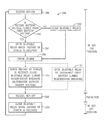
- FIG. 8 is a flow diagram describing an embodiment of a method for controlling a battery system, in accordance with an embodiment of the present approach.
- FIG. 9 is a perspective view of a prismatic battery cell used in a lithium ion battery, in accordance with an embodiment of the present approach.
- micro-hybrid vehicles disable the vehicle's internal combustion engine when the vehicle is idling. While the vehicle's internal combustion engine is disabled, the battery system may continue supplying power to the vehicle's electrical system, which may include the vehicle's radio, air conditioning, electronic control units, and the like. Additionally, regenerative braking vehicles capture and store electrical power generated when the vehicle is braking or coasting. In some embodiments, the generated electrical power may then be utilized to supply power to the vehicle's electrical system. In other embodiments, the generated electrical power may be utilized to stabilize voltage during high demand, for example in regenerative storage systems.
- manufactures which generally produce traditional gas-powered vehicles, may desire to utilize improved vehicle technologies (e.g., micro-hybrid technology or regenerative braking technology) within their vehicle lines. These manufactures often utilize one of their traditional vehicle platforms as a starting point.
- vehicle technologies e.g., micro-hybrid technology or regenerative braking technology
- manufactures often utilize one of their traditional vehicle platforms as a starting point.
- traditional gas-powered vehicles are designed to utilize 12 volt battery systems (e.g., voltage between 7-18 volts), such as a single 12 volt lead-acid battery.
- the single lead-acid battery may be adapted for the improved vehicle technologies.
- the lead-acid battery may be utilized to capture and store regenerative power and/or supply power to the electrical system during auto-stop.
- a lead-acid battery may be less efficient at capturing regenerative electrical power due to the lower coulombic efficiency and/or lower charge power acceptance rate associated with the lead-acid battery chemistry.
- coulombic efficiency and “charge power acceptance rate” may be used interchangeably to describe charging efficiency and charging rate.
- the lead-acid battery capacity may be increased to account for the electrical power demand during auto-stop, which may increase cost. As such, it would be beneficial to improve the efficiency of the power storage in the battery system and the efficiency of the power distribution to the vehicle's electrical system while largely conforming to existing vehicle electrical systems.
- present embodiments include physical battery system features, and so forth, that facilitate providing improved 12 volt battery systems.
- a “12 volt battery system” is intended to describe a battery system that supplies between 7-18 volts to an electrical system.
- the battery module may include multiple differing battery chemistries to improve the storage and distribution efficiency of the battery module. More specifically, as will be described in more detail below, the battery module may include a first battery (e.g., primary battery) with a first battery chemistry and a second battery (e.g., secondary battery) with a second battery chemistry.
- battery is intended describe energy storage devices that utilize various chemical reactions to store and/or distribute electrical power.
- the first battery and the second battery may operate in tandem.
- the first (e.g., primary) battery may efficiently supply large amounts of current, for example to crank the internal combustion engine
- the second battery e.g., power device
- the power stored in the second battery may be expended to provide power to the vehicle's electrical system.
- the first battery may be the primary source of electrical power and the second battery may supplement the battery, which in some embodiments may enable the storage capacity and/or the overall physical dimensions of the battery module to be reduced.
- the first battery and the second battery may be connected in various parallel architectures.
- the battery module may utilize a passive architecture or a semi-passive architecture.
- a passive architecture the first battery and the second battery may be directly coupled to terminals of the battery module, which may reduce complexity of a control algorithm for the battery system.
- a semi-passive architecture one of the first battery and the second battery may be coupled to the terminals of the battery module via a bi-stable relay while the other may be directly coupled.
- the bi-stable relay may increase the control over operation of the battery module by enabling either the first battery or the second battery to be selectively connected and disconnected.
- utilizing the techniques described herein may increase fuel economy and reduce undesirable emissions by 3-5% as compared to auto-stop technology utilizing traditional 12 volt battery systems (e.g., a single 12 volt lead-acid battery) because the load on the alternator is reduced by more efficiently capturing regenerative power.
- traditional 12 volt battery systems e.g., a single 12 volt lead-acid battery
- FIG. 1 is a perspective view of an embodiment of a vehicle 10 , which may utilize a regenerative braking system.
- a vehicle 10 which may utilize a regenerative braking system.
- the techniques described herein may be applied to other vehicles including xEV and gas-powered vehicles.
- the battery system 12 may be placed in a location in the vehicle 10 that would have housed a traditional battery system.
- the vehicle 10 may include the battery system 12 positioned similarly to a lead-acid battery of a typical combustion-engine vehicle (e.g., under the hood of the vehicle 10 ).
- the battery system 12 may be positioned to facilitate managing temperature of the battery system 12 .
- positioning a battery system 12 under the hood of the vehicle 10 may enable an air duct to channel airflow over the battery system 12 and cool the battery system 12 .
- the battery system 12 includes an energy storage component 14 coupled to an ignition system 16 , an alternator 18 , a vehicle console 20 , and optionally to an electric motor 22 .
- the energy storage component 14 may capture/store electrical energy generated in the vehicle 10 and output electrical energy to power electrical devices in the vehicle 10 .
- the energy storage component 14 may capture/store generated electrical energy and output electrical energy to power each of these components, as well as others.
- the battery system 12 may supply power to components of the vehicle's electrical system, which may include radiator cooling fans, climate control systems, electric power steering systems, active suspension systems, auto park systems, electric oil pumps, electric super/turbochargers, electric water pumps, heated windscreen/defrosters, window lift motors, vanity lights, tire pressure monitoring systems, sunroof motor controls, power seats, alarm systems, infotainment systems, navigation features, lane departure warning systems, electric parking brakes, external lights, or any combination thereof.
- the energy storage component 14 depicted in FIG. 2 supplies power to the vehicle console 20 and the ignition system 16 to start (e.g., crank) the internal combustion engine 24 .
- the ignition system 16 may include a traditional starter and/or a belt starter generator (BSG).
- BSG belt starter generator
- the energy storage component 14 may capture electrical energy generated by the alternator 18 and/or an electric motor 22 .
- the alternator 18 may generate electrical energy while an internal combustion engine 24 is running. More specifically, the alternator 18 may convert the mechanical energy produced by the rotation of the internal combustion engine 24 into electrical energy. Additionally or alternatively, when the vehicle 10 includes the electric motor 22 , the electric motor 22 may generate electrical energy by converting mechanical energy produced by the movement of the vehicle 10 (e.g., rotation of the wheels) into electrical energy. In other words, the energy storage component 14 may capture electrical energy generated during regenerative braking.
- the alternator 18 may be a variable voltage alternator, and the energy generated by the alternator 18 during regenerative braking may include a greater voltage than a voltage of the energy generated by the alternator 18 through the internal combustion engine 24 .
- the energy storage component 14 may be coupled to the vehicle's electric system via a bus 26 .
- the bus 26 may enable the energy storage component 14 to receive electrical energy generated by the alternator 18 and/or the electric motor 22 . Additionally, the bus may enable the energy storage component 14 to output electrical energy to the ignition system 16 and/or the vehicle console 20 . Accordingly, when a 12 volt battery system 12 is used, the bus 26 may carry electrical power typically between 8-18 volts.
- the energy storage component 14 may include multiple battery modules.
- the energy storage component 14 includes a first battery module 28 and a second battery module 30 , which each includes one or more battery cells.
- the energy storage component 14 may include any number of battery modules.
- the first battery module 28 and the second battery module 30 are depicted adjacent to one another, they may be positioned in different areas around the vehicle.
- the second battery module 30 may be positioned in or about the interior of the vehicle 10 while the first battery module 28 may be positioned under the hood of the vehicle 10 .
- the energy storage component 14 may include multiple battery modules to utilize multiple different battery chemistries.
- the first battery module 28 may utilize a lead-acid battery chemistry and the second battery module 30 may utilize a lithium ion battery chemistry.
- the performance of the battery system 12 may be improved since the lithium ion battery chemistry generally has a higher coulombic efficiency and/or a higher power charge acceptance rate (e.g., higher maximum charge current or charge voltage) than the lead-acid battery chemistry.
- the capture, storage, and/or distribution efficiency of the battery system 12 may be improved.
- the energy storage component 14 includes a first terminal 32 (i.e. a positive terminal) and a second terminal 34 (i.e., a ground terminal).
- the second terminal 34 may provide a ground connection and the first terminal 32 may provide a positive voltage ranging between 8-18 volts.
- the battery module 14 may have dimensions comparable to those of a typical lead-acid battery to limit modifications to the vehicle 10 design to accommodate the battery system 12 .
- the battery module 14 may be of similar dimensions to an H6 battery, which may be approximately 13.9 inches ⁇ 6.8 inches ⁇ 7.5 inches.
- the battery module 14 may be included within a single continuous housing.
- the battery module 14 may include multiple housings coupled together (e.g., a first housing including the first battery and a second housing including the second battery).
- the battery module 14 may include the first battery module 28 located under the hood of the vehicle 10 , and the second battery module 30 may be located within the interior of the vehicle 10 .
- the battery module 14 includes the first terminal 32 , the second terminal 34 , a first battery (e.g., a lead acid battery) 28 , a second battery 30 (e.g., a lithium ion battery), and a battery control unit 36 .
- the battery control unit 36 generally refers to control components that control operation of the battery system 12 , such as relays within the battery module or switches in the alternator 18 . The operation of the battery module 14 may be controlled by the battery control unit 36 .
- the battery control unit 36 may regulate amount of electrical energy captured/supplied by each battery module 28 or 30 (e.g., de-rate and re-rate the battery system 12 ), perform load balancing between the batteries, control charging and discharging of the batteries (e.g., via relays or DC/DC converters), determine a state of charge of each battery and/or the entire battery module 14 , activate an active cooling mechanism, and the like.
- the battery control unit 36 may include one or more memory 38 and one or more processor 40 programmed to execute control algorithms for performing such tasks. More specifically, the one or more processor 40 may include one or more application specific integrated circuits (ASICs), one or more field programmable gate arrays (FPGAs), one or more general purpose processors, or any combination thereof. Additionally, the one or more memory 38 may include volatile memory, such as random access memory (RAM), and/or non-volatile memory, such as read-only memory (ROM), optical drives, hard disc drives, or solid-state drives. In some embodiments, the battery control unit 36 may include portions of a vehicle control unit (VCU) and/or a separate battery control module. Additionally, as depicted, the battery control unit 36 may be included separate from the battery module 14 , such as a standalone module. In other embodiments, the battery control unit 36 may be included within the battery module 14 .
- VCU vehicle control unit
- the first battery 28 and the second battery 30 are connected in parallel across the first terminal 32 and the second terminal 34 to enable charging and discharging of the batteries.
- the battery terminals 32 and 34 may output the power stored in the battery module 14 to provide power to the vehicle's electrical system. Additionally, the battery terminals 32 and 34 may also input power to the battery module 14 to enable the first battery 28 and the second battery 30 to charge, for example, when the alternator 18 generates electrical power through regenerative braking.
- the first battery 28 and the second battery 30 may utilize various parallel architectures including a passive architecture or a semi-passive architecture.
- a passive battery system 42 is depicted
- a semi-passive architecture 50 is depicted.
- the first battery 28 and the second battery 30 are coupled in parallel with a starter (e.g., ignition system) 16 , an alternator (e.g., regenerative braking system) 18 , and the vehicle's electrical system 46 via the bus 26 .
- the first battery 28 and the second battery 30 are selectively connected to the ignition system 16 via a switch 48 .
- the switch 48 may represent various mechanisms, such as solenoids, that enable the first battery 28 and/or the second battery 30 to start (e.g., crank) the internal combustion engine 24 .
- the differences between the two architectures is the amount of control over the operation of each of the first battery 28 and the second battery 30 .
- the first battery 28 and the second battery 30 are directly coupled to the bus 26 . Accordingly, the operation of the first battery 28 and the second battery 30 may be controlled by the characteristics of each of the batteries. More specifically, the charging and discharging of the batteries 28 and 30 may be controlled by the current steering characteristics (e.g., internal resistance) of the first battery 28 (e.g., a lead-acid battery) and the second battery 30 (e.g., a lithium ion battery). For example, when the first battery 28 is fully charged or close to fully charged (e.g., generally full state of charge), the first battery 28 may have a high internal resistance that steers current toward the second battery 30 .
- the current steering characteristics e.g., internal resistance
- the first battery 28 e.g., a lead-acid battery
- the second battery 30 e.g., a lithium ion battery
- the current may be shared between the lead-acid battery 28 and the second battery 30 .
- the internal resistance may be proportionally related to the battery state of charge (e.g., high state of charge high internal resistance).
- the second battery 30 may provide power by itself, for example to a vehicle electrical system 46 , until it nears the open circuit voltage of the first battery. The exact voltage when the first battery 28 may begin providing power may be based on the various factors, such as the internal resistance of the batteries 28 and 30 and a diffusional resistance of the vehicle electrical system 46 .
- the first battery 28 and the second battery 30 are selectively connected to the ignition system 16 via a switch 48 .
- the switch 48 may represent various mechanisms, such as solenoids, that enable the first battery 28 (e.g., a lead-acid battery) and/or the second battery 30 to start (e.g., crank) the internal combustion engine 24 .
- a semi-passive architecture 50 may be utilized. More specifically, the semi-passive architecture 50 enables one of the batteries 28 or 30 to be selectively connected and disconnected from the bus 26 .
- FIG. 4A depicts an embodiment of a semi-passive architecture 50 A with a bi-stable relay 52 A included between the second battery 30 and the first terminal 32 while the first battery 30 is directly connected to the terminal 32 .
- a “bi-stable relay” is intended to describe any mechanism that can selectively connect and disconnect a battery while maintaining a stable state in either a connected or disconnected position.
- the bi-stable relay 52 may only consume power for an instant while the bi-stable relay 52 switches between positions.
- a standard relay may continuously consume power while the relay is in either or both of an open position and a closed position. Therefore, the bi-stable relay 52 may minimize power consumed from the battery system 12 . Further, it may be desirable to utilize the bi-stable relay 52 to minimize the risk of arcing, which may result from the use of a hardware switch.
- the battery control unit 36 may monitor information from the vehicle 10 to determine appropriate times to open or close the bi-stable relay 52 . For example, when the vehicle 10 transitions from a key-on to a key-off position, the battery control unit 36 may instruct the bi-stable relay 52 A to remain closed. While the bi-stable relay 52 A remains closed, any electrical loads on the vehicle 10 may be driven by the second battery 30 (e.g., a lithium ion battery) instead of the first battery 28 (e.g., a lead-acid battery).
- the second battery 30 e.g., a lithium ion battery
- the bi-stable relay 52 A may enable the second battery 30 to continue powering the electrical system 46 of the vehicle 10 when the vehicle 10 is transitioned to the key-off position. Additionally, the battery control unit 36 may maintain a coupling of the second battery 30 to the electrical system 46 for a predetermined about of time (e.g., 2-5 minutes), or until the second battery 30 reaches a predetermined voltage or state of charge to maintain a minimum voltage or state of charge level after the vehicle 10 transitions to the key-off position.
- a predetermined about of time e.g., 2-5 minutes
- the battery control unit 36 may determine whether the voltage of the second battery 30 is lower than the voltage of the first battery 28 . If so, the bi-stable relay 52 A may remain in an off position until the engine starts under power of the first battery 28 and until the alternator 18 is able to begin charging the second battery 30 (e.g., during regenerative braking).
- the bi-stable relay 52 A may immediately switch closed to couple the second battery 30 into the passive parallel configuration with the first battery 28 to assist in starting the internal combustion engine 24 . Further, if the battery control unit 36 determines that the voltage of the first battery 28 is too low to start the internal combustion engine 24 (i.e., the voltage of the first battery 28 is below a threshold voltage), the battery control unit 36 may close the bi-stable relay 52 A to allow the second battery 30 to provide the starting power for the ignition system 16 (i.e., allow the second battery 30 to “jump” the vehicle 10 ).
- FIG. 4B depicts an embodiment of a semi-passive architecture 50 B with a bi-stable relay 52 B included between the first battery 28 and the bus 26 while the second battery 30 is directly connected to the bus 26 .
- the bi-stable relay 52 B may be closed when it is desirable to charge or discharge the first battery 28 .
- the bi-stable relay 52 B may be open when the first battery 28 is neither charging nor discharging.
- current steering characteristics may control the operation of the second battery 30 while the battery control unit 36 may control the operation of the first battery 28 directly via the bi-stable relay 52 B.
- the bi-stable relay 52 B may open to remove the first battery 28 from the bus 26 when a key-off position is received by the vehicle 10 .
- the first battery 28 which may generally be relied on to crank the internal combustion engine 24 , may not be depleted by the various components of the electrical system 46 that remain active after the key-off position is received.
- the battery control unit 36 may instruct the bi-stable relay 52 B to close. In closing the bi-stable relay 52 B, the first battery 28 may be relied on to provide power to the ignition system 16 to crank the internal combustion engine 24 .
- the semi-passive architecture 50 embodiments may be similar to the passive battery system 42 embodiments.
- the semi-passive battery system architecture 50 A may improve the reliability of the battery system by enabling the second battery 30 to be disabled (e.g., disconnected from the vehicle 10 ) when it is undesirable to charge and/or discharge the second battery 30 .
- the semi-passive architecture 50 B may improve reliability of the battery system by enabling the first battery 28 to be disabled (e.g., disconnected from the vehicle 10 ) when it is undesirable to charge and/or discharge the first battery 28 , for example to protect the first battery 28 from overvoltage.
- operation of one of the batteries 28 or 30 may be directly controlled by the battery control unit 36 .
- FIG. 5 illustrates a plot 54 of battery voltage curves of two different battery chemistries that may be selected.
- a first battery chemistry may be selected for the first battery 28 and a second battery chemistry may be selected for the second battery 30 .
- the energy storage component 14 may function differently. More specifically, the chemistry pair selected may cause the first battery 28 and the second battery 30 to be non-voltage matched, partial voltage matched, or voltage matched.
- non-voltage matched is intended to describe when the first battery 28 and the second battery 30 open circuit voltage ranges do not overlap
- partial voltage matched is intended to describe when the first battery 28 and the second battery 30 open circuit voltage ranges partially overlap, for example when the voltage overlap corresponds to between 1-74% of the total state of charge range of the second battery 30
- voltage matched is intended to describe when the first battery 28 and the second battery 30 voltages largely overlap, for example when the voltage overlap corresponds to between 75-100% of the total state of charge range of the second battery 30 .
- the second battery 30 has a higher coulombic efficiency and/or a higher charge power acceptance rate than the first battery 28 .
- the battery pairing characteristics are described based on the relationship of the higher coulombic efficiency and/or a higher charge power acceptance rate battery (e.g., the second battery 30 ) to the other battery (e.g., the first battery 28 ).
- FIG. 5 is an XY plot depicting battery voltage curves.
- the first battery 28 will be described as a lead-acid battery and the second battery 30 will be described as a battery that utilizes a lithium ion battery chemistry.
- the voltage of each battery may vary with its state of charge (SOC).
- SOC state of charge
- a lead-acid battery 28 at 0% state of charge may have a voltage of 11.2 volts
- at 50% state of charge may have a voltage of 12.2 volts
- at 100% state of charge may have a voltage of 12.9 volts.
- the lead-acid battery has a voltage range of 11.2-12.9 volts.
- the lead-acid (PbA) battery 28 and the second battery 30 are partial voltage matched because an LTO/NMC voltage curve 56 and a PbA voltage curve 58 partially overlap.
- the open circuit voltage of the lead acid battery 28 and the second battery 30 may be the same.
- the lead-acid battery 28 has an open circuit voltage range of 11.2-12.9 volts and the LTO/NMC battery 30 has an open circuit voltage range between 11.8-16 volts.
- the first battery 28 and the second battery 30 may be partial voltage matched when the voltage overlap corresponds to between 1-74% of the second battery's total state of charge range.
- the first battery 28 and the second battery 30 may overlap between 11.8-12.9 volts.
- the voltages may overlap when the second battery 30 is between 0-20% state of charge (e.g., 20% of the total state of charge range).
- other battery chemistries for the second battery 30 may also partially overlap with the lead-acid battery 28 .
- the second battery 30 may include a battery chemistry of lithium-titanate at an anode of the second battery 30 and a blend of NMC and lithium cobalt oxide (LCO) at a cathode of the second battery 30 .
- the batteries 28 and 30 may also be non-voltage matched or voltage matched with the lead-acid battery 28 depending on the chemistry of the second battery 30 .
- the voltage pairing (e.g., non-voltage match, partial-voltage match, or voltage match) selected may determine the operation of the batteries 28 and 30 within the vehicle 10 .
- the lead-acid battery 28 and the second battery 30 are connected in various parallel architectures within the energy storage component 14 . Accordingly, when the energy storage component 14 is coupled to the vehicle 10 , the lead-acid battery 28 and the second battery 30 are also connected in parallel with the rest of the vehicle, such as the ignition system 16 , the alternator 18 (e.g., the regenerative braking system), and the electrical system 46 of the vehicle 10 .
- FIG. 6 is an XY plot that describes various vehicle operations between time 0 and time 8 , in which the Y-axis is vehicle speed and the X-axis is time (i.e., time 0 to time 8 ). More specifically, between time 0 and time 1 , the vehicle 10 is key-off 60 .
- key-off is intended to describe when an operator (e.g., a driver) is not using the vehicle 10 .
- key-off 60 may describe when the vehicle 10 is parked in a garage overnight.
- the internal combustion engine 24 is disabled and the battery system 12 continues to provide power to components of the vehicle's electrical system 46 that remain in operation even when the operator is away, such as an alarm system or engine control unit. Accordingly, as depicted, the vehicle has no speed.
- the vehicle 10 is cold cranked 62 .
- cold crank is intended to describe when an operator starts (i.e., cranks) the internal combustion engine 24 from key-off 60 . Accordingly, during cold crank 62 , the battery system 12 supplies power to the ignition system 16 (e.g., starter) to start the internal combustion engine 24 . After the internal combustion engine 24 is started, between time 1 and 2 , the vehicle 10 accelerates 64 . Accordingly, as depicted, the vehicle 10 increases speed. Between time 2 and time 3 , the vehicle 10 cruises 66 . Accordingly, as depicted, the vehicle 10 remains at a relatively constant speed.
- the ignition system 16 e.g., starter
- the battery system 12 supplies power to the vehicle's electrical system 46 , which may include the HVAC system and the vehicle console 20 .
- the alternator 18 may periodically be turned on, which, as will be described in more detail below, may result in micro-cycles. It should be noted that the embodiments described below may micro-cycle a battery 28 or 30 to achieve a target state of charge; however, additionally or alternatively, in other embodiments, the alternator 18 may supply power directly to the vehicle's electrical system 46 while the vehicle 10 is accelerating 64 and/or cruising 66 without micro-cycling the battery 28 or 30 . In other words, the alternator 18 may supply power directly to the vehicle's electrical system, for example while the vehicle 10 accelerates 64 or cruises 66 .
- the vehicle 10 decelerates and generates electrical power via regenerative braking 68 . Accordingly, as depicted, the vehicle 10 reduces speed. More specifically, the kinetic energy (e.g., motion of the vehicle) is converted into electrical power through the alternator 18 .
- the generated electrical power may be stored by the battery system 12 and/or distributed to supply power to the vehicle's electrical system 46 . As will be described in more detail below, depending on the configuration of the battery system 12 , the generated electrical power may be stored in and distributed from the first battery 28 , the second battery 30 , or both.
- the vehicle 10 again cruises 70
- time 5 and 6 the vehicle 10 again decelerates and generates electrical power via regenerative braking 72 .
- the vehicle 10 enters auto-stop 74 .
- the internal combustion engine 24 is disabled while the vehicle 10 is idle. Accordingly, as depicted, the vehicle has no speed.
- the battery system 12 warm cranks 76 the internal combustion engine 24 .
- “warm crank” is intended to refer to starting (i.e., cranking) the internal combustion engine 24 from auto-stop 74 .
- the power used to warm crank 76 the internal combustion engine 24 may be less than the power to cold crank 62 .
- the vehicle 10 again accelerates 78 between time 7 and time 8 .
- the battery system 12 While the vehicle is in auto-stop 74 , the battery system 12 continues to supply power to the vehicle's electrical system 46 . Additionally, this may include supplying power to the ignition system 16 to warm crank 76 the internal combustion engine 24 . However, while in auto-stop 74 , because the internal combustion engine 24 is disabled, the battery system 12 is not charged by the alternator 18 . Accordingly, as described above, it may be beneficial to improve the efficiency of the battery system 12 in storing (e.g., capturing) generated electrical power during regenerative braking (e.g., 68 or 72 ).
- regenerative braking e.g., 68 or 72
- distributing e.g., supplying
- stored electrical power during various vehicle operations (e.g., cruising 70 , auto-stop 74 , warm cranking 76 , and/or acceleration 78 ).
- the operation of the battery system 12 utilizing each of the voltage pairings will be described below with regard to the hypothetical vehicle operation described in FIG. 6 .
- the battery system 12 will be discussed in relation to an energy storage component 14 that includes both the lead-acid battery 28 and the second battery 30 .
- the lead-acid battery 28 and the second battery 30 may be located in different regions of the vehicle 10 , for example as separate modules.
- FIGS. 7A-7D describe the illustrative voltage of the semi-passive battery architecture 50 A, depicted in FIG. 4A , in relation to the hypothetical vehicle operation described above in FIG. 6 .
- FIGS. 7A-7D are XY plots that each includes a voltage curve that describes the dynamic voltage of the semi-passive architecture 50 A and a second battery voltage curve that describes the dynamic voltage of the second battery 30 between time 0 and time 8 , in which voltage is on the Y-axis and time is on the X-axis. More specifically, FIG. 7A describes a semi-passive architecture 50 A with a non-voltage matched battery pairing, FIG.
- FIG. 7B describes a semi-passive architecture 50 A with a first embodiment of a partial voltage matched battery pairing
- FIG. 7C describes a semi-passive architecture 50 A with a second embodiment of a partial voltage matched battery pairing
- FIG. 7D describes a semi-passive architecture 50 A with a voltage matched battery pairing.
- the semi-passive embodiments are similar to their respective passive battery system embodiments. Accordingly, to more efficiently capture electrical power generated via regenerative braking, the lead-acid battery 28 may generally be operated between 95-100% state of charge and the second battery 30 may generally be operated at 0% state of charge. In other words, the lead-acid battery 28 is maintained at a relatively full state of charge to steer the generated electrical power to the second battery 30 , and the second battery 30 is maintained at a relatively empty state of charge to utilize the full storage capacity (i.e., 0-100% state of charge) of the second battery 30 .
- the lead-acid battery 28 may generally be operated between 95-100% state of charge and the second battery 30 may generally be operated at 0% state of charge.
- the lead-acid battery 28 is maintained at a relatively full state of charge to steer the generated electrical power to the second battery 30
- the second battery 30 is maintained at a relatively empty state of charge to utilize the full storage capacity (i.e., 0-100% state of charge) of the second battery 30 .
- FIG. 7A depicts that the battery system voltage 80 decreases as the lead-acid battery supplies electrical power to the component of the electrical system 46 during key-off 82 (e.g., between time 0 and time 1 ), sharply drops as the lead-acid battery 28 cold cranks 84 the internal combustion engine 24 (e.g., at time 1 ), micro-cycles while the vehicle accelerates 86 and cruises 88 (e.g., between time 1 and time 3 ), increases as electrical power is stored in the second battery 30 during regenerative braking 90 (e.g., between time 3 and time 4 ), decreases as the second battery 30 supplies electrical power to the electrical system 46 during cruising 92 (e.g., between time 4 and time 5 ), increases as electrical power is again stored in the second battery 30 during regenerative braking 94 (e.g., between time 5 and time 6 ), decreases as the second battery 30 supplies electrical power to the electrical system 46 during auto-stop 96 (e.g., between time 6 and time 7 ), sharply
- the bi-stable relay 52 A may be closed when it is desirable to charge or discharge the second battery 30 .
- the bi-stable relay 52 A may be open to enable the lead-acid battery 28 to supply electrical power to the electrical system 46 by itself.
- voltage 102 of the second battery is maintained at approximately 13.3 volts (e.g., 0% state of charge).
- the bi-stable relay 52 A may be closed to enable the second battery 30 to charge, for example during regenerative braking 90 and 94 , and discharge for example during cruising 92 and auto-stop 96 . Furthermore, the bi-stable relay 52 A may remain closed until the electrical power stored in the second battery 30 is depleted 100 . Accordingly, since the second battery 30 contains approximately 60% state of charge, the lead-acid battery 28 along with the second battery 30 may both supply power to warm crank 98 the internal combustion engine as depicted.
- whether to utilize the second battery 30 to crank the internal combustion engine may be based at least in part on a minimum state of charge for the second battery.
- the minimum state of charge may be 20%, 40%, or 60% of second battery state of charge.
- “minimum state of charge” is intended to describe the minimum amount of power, which is a function of the battery state of charge, which may be contributed by the second battery 30 to facilitate a vehicle operation, such as crank the internal combustion engine 24 or supply power to the electrical system 46 .
- the bi-stable relay 52 A may be open, disconnecting the second battery 30 and enabling the lead-acid battery 28 to supply power to the electrical system 46 by itself.
- FIG. 7B describes a semi-passive battery system 50 A when the batteries 28 and 30 are partial voltage matched, in accordance with a first embodiment.
- FIG. 7B depicts a battery system voltage curve 104 and a second battery voltage curve 106 , in accordance with the first embodiment. More specifically, the voltage curves 104 and 106 are based on the voltage characteristics described in FIG. 5 . In other words, a lead-acid battery 28 and a LTO/NMC battery 30 .
- the lead-acid battery 28 may be operated between 95-100% state of charge to steer regenerative power toward the second battery 30 , which may capture regenerative power more efficiently. Additionally, based on the voltage characteristics of the batteries 28 and 30 (e.g., current steering), the second battery 30 may supply power by itself until its voltage nears the lead-acid battery voltage.
- the “first embodiment” of a partial voltage match battery system is intended to describe maintaining the battery 28 (e.g., lead-acid battery) generally at a full state of charge (e.g., 100% state of charge) and maintaining the second battery 28 at the state of charge corresponding with the threshold voltage (e.g., 20% state of charge).
- the threshold voltage e.g. 20% state of charge
- the battery system voltage 104 decreases as the lead-acid battery 28 supplies electrical power to the electrical system 46 during key-off 108 (e.g., between time 0 and time 1 ), sharply drops as the lead-acid battery 28 cold cranks 110 the internal combustion engine (e.g., at time 1 ), micro-cycles (e.g., to maintain the lead-acid battery 28 between 95-100% state of charge) while the vehicle accelerates 112 and cruises 114 (e.g., between time 1 and time 3 ), increases as electrical power is stored in the second battery 30 during regenerative braking 116 (e.g., between time 3 and time 4 ), decreases as the battery system supplies electrical power to the electrical system 46 during cruising 118 (e.g., between time 4 and time 5 ), increases as electrical power is again stored in the second battery 30 during regenerative braking 120 (e.g., between time 5 and time 6 ), decreases as the battery system supplies electrical power to the electrical system 46 during auto-stop 122
- the bi-stable relay 52 A is open between time 0 and time 3 (e.g., key-off 108 , cold crank 110 , acceleration 112 , and cruising 114 ) to enable the lead-acid battery 28 to supply power to the electrical system 46 by itself. Additionally, the bi-stable relay 52 A may open after the second battery 30 has discharged to the threshold voltage. For example, in the depicted embodiment, the bi-stable relay 52 A is open during micro-cycling 128 and discharging 130 to disconnect the second battery 30 from the electrical system 46 . Accordingly, as depicted, the second battery voltage 106 remains relatively constant during these periods.
- the second battery voltage 106 may experience some decay due to voltage relaxation and/or self-discharge. Furthermore, in the depicted embodiment, since the bi-stable relay 52 A is open, the lead-acid battery 28 supplies power to warm crank 124 the internal combustion engine 24 by itself.
- the bi-stable relay 52 A may be closed to enable the second battery 30 to charge/discharge.
- the bi-stable relay 52 A is closed during regenerative braking 116 and 120 to charge the second battery 30 .
- the bi-stable relay 52 A is closed while the second battery 30 supplies power, for example during the portion of cruising 118 and auto-stop 122 before reaching its threshold voltage (e.g., before micro-cycling 128 and discharging 130 ). More generally, the bi-stable relay 52 A may be closed when electrical power is desired by the electrical system 46 and the second battery 30 is above a minimum state of charge.
- the amount of regenerative power utilized by the second battery 30 may be less than its full storage capacity. Accordingly, in a second embodiment of a semi-passive battery architecture 50 A with partial voltage matched batteries, the threshold voltage may be reduced to increase the amount of regenerative power that may be captured and supplied by the second battery 30 . For example, the threshold voltage is lowered to approximately 12.6 volts in the second embodiment described in FIG. 7C , which depicts a battery system voltage curve 132 that describes the voltage of the battery system 12 and a second battery voltage curve 134 that describes the voltage of the second battery 30 .
- the voltage curves 132 and 134 are based on the voltage characteristics described in FIG. 5 .
- the lead-acid battery 28 is generally maintained at between 80-85% state of charge and the second battery 30 is generally maintained at 15% state of charge.
- the second battery 30 may utilize 85% of its storage capacity (e.g., 15-100% state of charge) to capture regenerative power, which is a 5% state of charge increase over the first embodiment (e.g., 80%).
- the threshold voltage may be lowered by maintaining the lead-acid battery 28 between 50-55%, 55-60%, 60-65%, 65-70%, 70-75%, 85-90% state of charge, or any combination thereof.
- the “second embodiment” of a partial voltage match battery system is intended to describe maintaining the first battery 28 (e.g., lead-acid battery) at a generally less than full state of charge (e.g., between 80-85% state of charge) to lower the threshold voltage.
- first battery 28 e.g., lead-acid battery
- full state of charge e.g., between 80-85% state of charge
- the battery system voltage 132 decreases as the lead-acid battery 28 supplies electrical power to the component of the electrical system 46 during key-off 136 (e.g., between time 0 and time 1 ), sharply drops as the lead-acid battery 28 cold cranks 138 the internal combustion engine (e.g., at time 1 ), micro-cycles (e.g., to maintain the lead-acid battery between 80-85% state of charge) while the vehicle accelerates 140 and cruises 142 (e.g., between time 1 and time 3 ), increases as electrical power is stored in the second battery 30 during regenerative braking 144 (e.g., between time 3 and time 4 ), decreases as the second battery 30 supplies electrical power to the electrical system 46 during cruising 146 (e.g., between time 4 and time 5 ), increases as electrical power is again stored in the second battery 30 during regenerative braking 148 (e.g., between time 5 and time 6 ), decreases as the second battery 30 supplies electrical power to the electrical system 46 during key-off 136 (e
- the bi-stable relay 52 A is open between time 0 and time 3 (e.g., key-off 136 , cold crank 138 , acceleration 140 , and cruising 142 ) to enable the lead-acid battery 28 to supply power to the electrical system 46 by itself. Additionally, the bi-stable relay 52 A may open after the second battery 30 has discharged to the threshold voltage. For example, in the depicted embodiment, the bi-stable relay 52 A opens to disconnect the second battery 30 , and the lead-acid battery 28 provides power (e.g., during micro-cycling 156 ).
- the second battery voltage 134 remains at a relatively constant voltage during these periods. Furthermore, since the second battery 30 has not reached the threshold voltage, the second battery 30 along with the lead-acid battery 28 may both supply power to warm crank 152 the internal combustion engine 24 .
- the bi-stable relay 52 A may be closed to enable the second battery 30 to charge/discharge.
- the bi-stable relay 52 A is closed during regenerative braking 144 and 148 to charge the second battery 30 .
- the bi-stable relay 52 A is closed while the second battery 30 supplies power, for example during cruising 146 and auto-stop 150 .
- FIG. 7D describes a semi-passive architecture 50 A when the batteries 28 and 30 are voltage matched.
- a lead-acid battery 28 and a LTO/LMO battery 30 for example.
- FIG. 7D depicts a battery system voltage curve 158 that describes the voltage of the battery system and a second battery voltage curve 160 that describes the voltage of the second battery 30 .
- the second battery 30 may supply power to the electrical system 46 by itself until the second battery 30 nears the threshold voltage. Accordingly, similar to the second embodiment of the partial voltage match described above, the threshold voltage may be reduced to increase the storage capability of the second battery 30 .
- the lead-acid battery 28 is generally maintained at between 95-100% state of charge and the second battery 30 is maintained at approximately 75% state of charge.
- the second battery 30 is capable of utilizing 25% of its storage capacity to capture regenerative power (e.g., 75-100% state of charge).
- the threshold voltage is reduced to approximately 12.3 volts
- the lead-acid battery 28 is generally maintained at between 60-65% state of charge (e.g., generally less than full state of charge) and the second battery 30 is generally maintained at 35% state of charge.
- the second battery 30 is capable of utilizing 65% of its storage capacity to capture regenerative power (e.g., 35-100% state of charge).
- the battery system voltage 158 decreases as the lead-acid battery 28 supplies electrical power to the component of the electrical system 46 during key-off 162 (e.g., between time 0 and time 1 ), sharply drops as the lead-acid battery 28 cold cranks 164 the internal combustion engine (e.g., at time 1 ), micro-cycles (e.g., to maintain the lead-acid battery between 60-65% state of charge) while the vehicle accelerates 166 and cruises 168 (e.g., between time 1 and time 3 ), increases as electrical power is stored in the second battery 30 during regenerative braking 170 (e.g., between time 3 and time 4 ), decreases as the battery system supplies electrical power to the electrical system 46 during cruising 172 (e.g., between time 4 and time 5 ), increases as electrical power is again stored in the second battery 30 during regenerative braking 174 (e.g., between time 5 and time 6 ), decreases as the battery system supplies electrical power to the electrical system 46
- the bi-stable relay 52 A is open between time 0 and time 3 (e.g., key-off 162 , cold crank 164 , acceleration 166 , and cruising 168 ) to enable the lead-acid battery 28 to supply power to the electrical system 46 by itself.
- the bi-stable relay 52 A may open after the second battery 30 has discharged to the threshold voltage.
- the threshold voltage when the threshold voltage is reached, the bi-stable relay 52 A opens to disconnect the Second battery 30 during micro-cycling 182 or discharging 128 .
- the LTO/LMO battery voltage 160 remains at a relatively constant voltage during these periods.
- the lead-acid battery 28 supplies power to warm crank 178 the internal combustion engine 24 by itself.
- the bi-stable relay 52 A may be closed to enable the second battery 30 to charge/discharge.
- the bi-stable relay 52 A is closed during regenerative braking 170 and 174 to charge the second battery 30 .
- the bi-stable relay 52 A is closed while the second battery 30 supplies power, for example during the portion of cruising 172 and auto-stop 176 before reaching its threshold voltage (e.g., before micro-cycling 182 and discharging 184 ).
- the bi-stable relay 52 A may be open to disconnect the second battery 30 when it is undesirable to charge or discharge the second battery 30 .
- the bi-stable relay 52 A may be open when the lead-acid battery 28 is supplying power (e.g., during key-off, cold crank, acceleration, and cruising).
- the bi-stable relay 52 A may be open when the second battery 30 discharges to the threshold voltage (e.g., 128 , 130 , 156 , 182 , or 184 ).
- the lead-acid battery 28 along with the second battery 30 may supply power during key-off (e.g., 118 , 146 , or 168 ), and the alternator 18 may micro-cycle both the lead-acid battery 28 and the second battery 30 because the second battery 30 is directly coupled to the bus 26 .
- key-off e.g., 118 , 146 , or 168
- micro-cycling the lead-acid battery 28 by itself may increase the vehicle's fuel economy and/or reduce undesirable emissions because the alternator 18 charges a single battery (e.g., the lead-acid battery 28 ) as compared to two batteries (e.g., the lead-acid battery 28 and the second battery 30 ). Additionally, not micro-cycling the second battery 30 may improve the lifespan of the second battery 30 because the second battery 30 is not repeatedly charged and discharged during micro-cycling. Accordingly, the overall cost of a semi-passive architecture 50 A may be reduced based on these factors.
- the bi-stable relay 52 B may improve the lifespan of the lead-acid battery 28 and improve the recharge efficiency of the second battery 30 .
- the bi-stable relay 52 B may disconnect the lead-acid battery 28 during regenerative braking to steer all of the regenerative power to the second battery 30 , which more efficiently captures the regenerative power.
- the bi-stable relay 52 B may disconnect the lead-acid battery 28 to enable the second battery 30 to be charged at a higher voltage (e.g., 16.8 volts), which may be higher than the maximum charging voltage of to the lead-acid battery 28 (e.g., overvoltage), to improve the charging rate of the second battery 30 .
- the alternator 18 may output a voltage up to 16.8 volts to charge the second battery 30 .
- the maximum charging voltage of lead-acid battery 28 may be 14.8 volts because above that point the lead-acid battery 28 may begin to produce oxygen and hydrogen gas, which negatively affects the lifespan of the lead-acid battery 28 .
- the bi-stable relay 52 B may be opened to enable the second battery 30 to be more optimally charged while protecting the lead-acid battery 28 from overvoltage, for example when the batteries 28 and 30 are non-voltage matched or partial voltage matched.
- the control algorithm utilized by the battery control unit 36 may be more complex than the algorithm utilized for passive battery systems 42 . More specifically, in addition to controlling the alternator 18 , the battery control unit 36 may close and open the bi-stable relay 52 to control the operation of the semi-passive architecture 50 . As described above, the bi-stable relay 52 may be closed when the battery 28 or 30 is charging or discharging and open otherwise. Further, FIG. 8 illustrates a method 186 to determine desirable times for opening and closing the bi-stable relay 52 A during key-on and key-off times. Initially, at block 188 , the vehicle 10 may receive a key-on signal indicating that the car is starting from an off position.
- the battery control unit 36 may make a determination, at block 190 , of whether the voltage of the second battery 30 is lower than the voltage of the first battery 28 . In making this determination, the battery control unit 36 determines whether the state of charge of the second battery 30 is high enough to provide support to the first battery 28 while starting the internal combustion engine 24 .
- the battery control unit 36 may instruct the bi-stable relay 52 A to close at block 192 .
- the bi-stable relay 52 A With the bi-stable relay 52 A closed, the second battery 30 couples to the bus 26 .
- the second battery 30 may be used to assist the first battery 28 with starting the internal combustion engine 24 .
- the battery control unit 36 may instruct the bi-stable relay 52 A to open at block 194 .
- the voltage of the second battery 30 is lower than the voltage of the first battery 28 , it may indicate that the state of charge of the second battery 30 is very low. While the state of charge of the second battery 30 is very low, the first battery 28 may be relied on exclusively to start the vehicle 10 so as to avoid depleting the state of charge of the second battery 30 even further. In this manner, the second battery 30 may be recharged to a more functional state of charge with greater efficiency once the first battery 28 starts the vehicle 10 .
- the first battery 28 or the batteries 28 and 30 may crank the internal combustion engine 24 at block 196 .
- the vehicle 10 may begin recharging the batteries or micro-cycling the batteries, as discussed above.
- the battery control unit 36 may continue to open or close the bi-stable relay 52 A, depending on the situation, as discussed above in the discussion for FIGS. 7A-7D .
- the battery control unit 36 may instruct the bi-stable relay 52 A to close when the vehicle 10 is undergoing regenerative braking to recharge the second battery 30 at block 195 .
- an alternator is configured to output a first voltage during regenerative braking to charge the second battery and to output a second voltage otherwise, wherein the first voltage is higher than the second voltage.
- the battery control unit 36 may instruct the bi-stable relay 52 A to open to disconnect the first battery 28 during regenerative breaking at block 197 .
- the battery control unit 36 may instruct the bi-stable relay 52 A to open when the second battery 30 drops below a threshold voltage indicating a low state of charge.
- the vehicle 10 may receive a key-off indication indicating that a user has stopped the internal combustion engine 24 of the vehicle 10 .
- the battery control unit 36 may instruct the bi-stable relay 52 A to close. Once the bi-stable relay 52 A is closed, components of the electrical system 46 that remain operational when the vehicle 10 is off (e.g., lights, fans, engine control modules, accessories, door locks, etc.) may be powered by the second battery 30 .
- the second battery 30 may continue to power the components after the key-off indication until the second battery 30 reaches a predetermined threshold voltage, a predetermined amount of time has passed since receiving the key-off indication (e.g., 2-5 minutes), or the opening of a door of the vehicle 10 indicating an exit of passengers from the vehicle 10 . Further, the method 186 may restart at block 188 upon completing block 200 .
- the battery control unit 36 may open the bi-stable relay 52 B to enable the second battery 30 to be optimally charged (e.g., with a higher charging voltage) while protecting the lead-acid battery 28 from overvoltage. Accordingly, the battery control unit 36 may turn on/off the alternator 18 as well as open/close the bi-stable relay 52 B to maintain each of the batteries 28 and 30 at their respective target states of charge. In addition to opening/closing the bi-stable relay 52 B to facilitate maintaining the batteries 28 and 30 at their target states of charge, the battery control unit 36 may disconnect the battery 28 or 30 for other reasons, such as extreme temperatures that may cause one of the batteries 28 or 30 to be outside of its optimum operating zones.
- the battery cells described herein may be prismatic battery cells 202 , where a prismatic battery cell 202 , as defined herein, includes a prismatic case that is generally rectangular in shape. In contrast to pouch cells, the prismatic casing is formed from a relatively inflexible, hard (e.g., metallic) material. However, it should be noted that certain of the embodiments described below may incorporate pouch cells in addition to or in lieu of prismatic battery cells.
- each prismatic battery cell may include a top casing portion 204 , where a set of cell terminals 32 , 34 (e.g., positive and negative cell terminals) are located.
- One or more cell vents 206 may also be located on the top casing portion 204 .
- the prismatic cell casing also includes a bottom casing portion 208 positioned opposite the top casing portion 204 .
- First and second sides 210 , 212 which may be straight or rounded, extend between the bottom and top casing portions 208 , 204 in respective positions corresponding to the cell terminals 32 , 34 .
- First and second faces 214 , 216 which may be flat (as shown) or rounded, couple the first and second sides 210 , 212 at opposing ends of each cell 202 .
- One or more of the disclosed embodiments may provide one or more technical effects including coupling and decoupling the first battery 28 or the second battery 30 from the electrical system 46 based on operational situations of the vehicle 10 .
- the technical effects and technical problems in the specification are exemplary and are not limiting. It should be noted that the embodiments described in the specification may have other technical effects and can solve other technical problems.
Abstract
Description
Claims (20)
Priority Applications (5)
| Application Number | Priority Date | Filing Date | Title |
|---|---|---|---|
| US14/502,158 US10320202B2 (en) | 2014-09-30 | 2014-09-30 | Battery system bi-stable relay control |
| PCT/US2015/036992 WO2016053419A1 (en) | 2014-09-30 | 2015-06-22 | Battery system bi-stable relay control |
| EP15741659.5A EP3201036B1 (en) | 2014-09-30 | 2015-06-22 | Battery system bi-stable relay control |
| CN201580057057.8A CN107107772B (en) | 2014-09-30 | 2015-06-22 | Battery system in vehicle |
| US16/436,662 US11190026B2 (en) | 2014-09-30 | 2019-06-10 | Battery system to be deployed in a vehicle having a first battery and a second battery, battery control unit to be deployed in a battery system of a vehicle, and method related to the same |
Applications Claiming Priority (1)
| Application Number | Priority Date | Filing Date | Title |
|---|---|---|---|
| US14/502,158 US10320202B2 (en) | 2014-09-30 | 2014-09-30 | Battery system bi-stable relay control |
Related Child Applications (1)
| Application Number | Title | Priority Date | Filing Date |
|---|---|---|---|
| US16/436,662 Continuation US11190026B2 (en) | 2014-09-30 | 2019-06-10 | Battery system to be deployed in a vehicle having a first battery and a second battery, battery control unit to be deployed in a battery system of a vehicle, and method related to the same |
Publications (2)
| Publication Number | Publication Date |
|---|---|
| US20160089992A1 US20160089992A1 (en) | 2016-03-31 |
| US10320202B2 true US10320202B2 (en) | 2019-06-11 |
Family
ID=53719935
Family Applications (2)
| Application Number | Title | Priority Date | Filing Date |
|---|---|---|---|
| US14/502,158 Active 2035-05-07 US10320202B2 (en) | 2014-09-30 | 2014-09-30 | Battery system bi-stable relay control |
| US16/436,662 Active US11190026B2 (en) | 2014-09-30 | 2019-06-10 | Battery system to be deployed in a vehicle having a first battery and a second battery, battery control unit to be deployed in a battery system of a vehicle, and method related to the same |
Family Applications After (1)
| Application Number | Title | Priority Date | Filing Date |
|---|---|---|---|
| US16/436,662 Active US11190026B2 (en) | 2014-09-30 | 2019-06-10 | Battery system to be deployed in a vehicle having a first battery and a second battery, battery control unit to be deployed in a battery system of a vehicle, and method related to the same |
Country Status (4)
| Country | Link |
|---|---|
| US (2) | US10320202B2 (en) |
| EP (1) | EP3201036B1 (en) |
| CN (1) | CN107107772B (en) |
| WO (1) | WO2016053419A1 (en) |
Cited By (3)
| Publication number | Priority date | Publication date | Assignee | Title |
|---|---|---|---|---|
| EP1878604A1 (en) | 2006-07-11 | 2008-01-16 | Delphi Technologies, Inc. | Method of mitigating driver distraction |
| US20190036374A1 (en) * | 2016-03-16 | 2019-01-31 | Autonetworks Technologies, Ltd. | Vehicle power supply system and vehicle drive system |
| US11190026B2 (en) | 2014-09-30 | 2021-11-30 | Cps Technology Holdings Llc | Battery system to be deployed in a vehicle having a first battery and a second battery, battery control unit to be deployed in a battery system of a vehicle, and method related to the same |
Families Citing this family (25)
| Publication number | Priority date | Publication date | Assignee | Title |
|---|---|---|---|---|
| DE102014006028B4 (en) * | 2014-04-24 | 2022-06-30 | Audi Ag | Multi-battery system to increase the electric range |
| US9776635B2 (en) * | 2015-02-09 | 2017-10-03 | Ford Global Technologies, Llc | Apparatus and method to maximize vehicle functionality and fuel economy with improved drivability during engine auto stop-start operations |
| US10333337B2 (en) * | 2015-11-30 | 2019-06-25 | Volta Power Systems, L.L.C. | Secondary power system |
| JP6736399B2 (en) * | 2016-07-20 | 2020-08-05 | Ntn株式会社 | Electric brake device and electric brake system |
| US10974606B2 (en) * | 2016-08-31 | 2021-04-13 | Cps Technology Holdings Llc | Bi-stable relay |
| US11146084B2 (en) * | 2016-09-02 | 2021-10-12 | Superior Communications, Inc. | Car charger with cable and LED activated when devices are connected to connectors |
| JP6597664B2 (en) * | 2017-02-14 | 2019-10-30 | トヨタ自動車株式会社 | Vehicle control device |
| DE102017104958B4 (en) * | 2017-03-09 | 2024-03-14 | Dr. Ing. H.C. F. Porsche Aktiengesellschaft | Battery storage system |
| JP7016628B2 (en) * | 2017-07-11 | 2022-02-07 | ビークルエナジージャパン株式会社 | Combined power storage system |
| US11052274B2 (en) * | 2017-07-18 | 2021-07-06 | Charlton Michael Hobson | Method and apparatus for exercise energy utilization |
| CN107914546B (en) * | 2017-12-08 | 2023-08-01 | 东莞理工学院 | Solar device for heat dissipation and refrigeration of automobile and automobile |
| CN107887955B (en) * | 2017-12-18 | 2023-05-23 | 厦门芯阳科技股份有限公司 | Bistable key switch driving circuit capable of being automatically closed under low voltage |
| IT201800002823A1 (en) * | 2018-02-19 | 2019-08-19 | Fiat Ricerche | OPERATION MANAGEMENT OF A DOUBLE BATTERY AUTOMOTIVE ELECTRIC SYSTEM WITH KINETIC ENERGY RECOVERY DURING BRAKING |
| JP7119524B2 (en) * | 2018-04-17 | 2022-08-17 | 株式会社デンソー | power control unit |
| EP3934054A1 (en) * | 2019-01-29 | 2022-01-05 | Google LLC | Methods and systems for battery management |
| KR20200128848A (en) * | 2019-05-07 | 2020-11-17 | 현대자동차주식회사 | Battery control method using latching relay and battery system using the same |
| FR3097493B1 (en) * | 2019-06-20 | 2021-07-23 | Commissariat Energie Atomique | Hybrid electrical energy storage system |
| US20210066953A1 (en) * | 2019-08-28 | 2021-03-04 | Delphi Automotive Systems Luxembourg Sa | Systems and methods for smooth start up of vehicle onboard battery charger |
| CN110570642B (en) * | 2019-09-04 | 2021-05-18 | 航宇救生装备有限公司 | Power supply on-off control circuit and control method for remote control system |
| US20210129687A1 (en) * | 2019-11-01 | 2021-05-06 | GM Global Technology Operations LLC | System and process for utilizing a deployable flex range battery to augment a primary battery |
| US20210143663A1 (en) * | 2019-11-08 | 2021-05-13 | Oshkosh Corporation | Power system for a vehicle |
| JP2021112086A (en) * | 2020-01-15 | 2021-08-02 | トヨタ自動車株式会社 | Power supply system of vehicle |
| JP2021164339A (en) * | 2020-04-01 | 2021-10-11 | マツダ株式会社 | Vehicle battery system |
| DE102020129131A1 (en) * | 2020-11-05 | 2022-05-05 | Dr. Ing. H.C. F. Porsche Aktiengesellschaft | Method and system for monitoring the state of charge of an AC battery |
| KR20220146131A (en) * | 2021-04-23 | 2022-11-01 | 현대자동차주식회사 | Vehicle and method of controlling the same |
Citations (110)
| Publication number | Priority date | Publication date | Assignee | Title |
|---|---|---|---|---|
| US313117A (en) * | 1885-03-03 | Apparatus for charging and discharging secondary batteries | ||
| US3560818A (en) * | 1969-02-03 | 1971-02-02 | Ford Motor Co | Reluctance motor power circuit using dual energy sources |
| US3917017A (en) * | 1974-01-25 | 1975-11-04 | West Virginia High Bird Corp E | Battery operated vehicle drive |
| US3947744A (en) * | 1974-10-21 | 1976-03-30 | Allis-Chalmers Corporation | Electric truck having elevated load potential energy recovery with means to adjust rate of carriage descent |
| US3959701A (en) * | 1972-08-02 | 1976-05-25 | Firma Deutsche Automobilgesellschaft Mbh | Drive system for electrically driven vehicles |
| US4004208A (en) * | 1973-12-17 | 1977-01-18 | Pentti Juuse Tamminen | Starting aid and reserve light for vehicles |
| US4025860A (en) * | 1974-09-14 | 1977-05-24 | Agency Of Industrial Science & Technology | Control system for battery hybrid system |
| US4218717A (en) * | 1978-08-21 | 1980-08-19 | Harry Shuster | Electric control system for motor vehicle |
| US4345197A (en) * | 1980-03-03 | 1982-08-17 | General Motors Corporation | Vehicle battery charging system |
| US4348628A (en) * | 1980-06-20 | 1982-09-07 | Loucks Carl C | Electric motor alternating power supply for vehicles |
| US5204610A (en) * | 1991-02-15 | 1993-04-20 | Globe-Union, Inc. | Long lived dual battery with automatic latching switch |
| US5285862A (en) * | 1992-03-16 | 1994-02-15 | Toyota Jidosha Kabushiki Kaisha | Power supply system for hybrid vehicles |
| US5355071A (en) * | 1991-04-24 | 1994-10-11 | Nippondenso Co., Ltd. | Power source apparatus for vehicles |
| US5373195A (en) * | 1992-12-23 | 1994-12-13 | General Electric Company | Technique for decoupling the energy storage system voltage from the DC link voltage in AC electric drive systems |
| US5488283A (en) * | 1993-09-28 | 1996-01-30 | Globe-Union, Inc. | Vehicle battery system providing battery back-up and opportunity charging |
| US5542488A (en) | 1993-04-08 | 1996-08-06 | Nixon; Dale B. | Electric vehicle having multiple replacement batteries |
| US5670861A (en) * | 1995-01-17 | 1997-09-23 | Norvik Tractions Inc. | Battery energy monitoring circuits |
| US5780980A (en) * | 1995-04-14 | 1998-07-14 | Hitachi, Ltd. | Electric car drive system provided with hybrid battery and control method |
| US5844325A (en) * | 1995-06-22 | 1998-12-01 | Glory Win International Group Ltd. | Vehicle dual battery controller utilizing motion sensor |
| US5893124A (en) * | 1992-12-03 | 1999-04-06 | Kabushiki Kaisha Toshiba | Job processing apparatus and method for preparing an instruction sheet having a predetermined format and for executing an instruction included on the instruction sheet |
| US5977744A (en) * | 1996-10-26 | 1999-11-02 | Lucas Industries | Vehicle battery controller |
| US6229279B1 (en) * | 1998-09-17 | 2001-05-08 | Volkswagen Ag | Dual battery system |
| US20010040441A1 (en) * | 2000-05-08 | 2001-11-15 | Ng Wai Man | Intelligent switch for battery |
| US20010040060A1 (en) * | 2000-05-11 | 2001-11-15 | Kazuhiko Morimoto | Power-generating control apparatus for vehicle |
| US6452361B2 (en) * | 1998-02-13 | 2002-09-17 | Johnson Controls Technology Company | Battery system |
| US20030105562A1 (en) * | 2001-11-30 | 2003-06-05 | Industrial Technology Research Institute | Power output control system for electric vehicle with hybrid fuel cell |
| US20030118876A1 (en) * | 2001-12-19 | 2003-06-26 | Toyota Jidosha Kabushiki Kaisha | Power supply apparatus with fuel cell and capacitor |
| CN1440583A (en) | 2000-05-08 | 2003-09-03 | 新晖贸易有限公司 | Intelligent switch for battery |
| US20030210014A1 (en) * | 2002-05-07 | 2003-11-13 | C.E. Niehoff & Co. | System and method for controlling electric load and battery charge in a vehicle |
| US20040053083A1 (en) | 2002-09-18 | 2004-03-18 | Nissan Motor Co., Ltd. | Vehicular electric power generation control apparatus |
| US20040076860A1 (en) * | 2002-10-22 | 2004-04-22 | Nissan Motor Co., Ltd. | Fuel cell system and related control method |
| US20040232861A1 (en) * | 2001-09-21 | 2004-11-25 | Teruo Wakashiro | Control device for hybrid vehicle |
| US20050212491A1 (en) * | 2002-08-02 | 2005-09-29 | Paolo Colombo | Protection system of a vehicle battery |
| US7119516B2 (en) * | 2004-05-04 | 2006-10-10 | O2Micro International Limited | Cordless power tool with tool identification circuitry |
| US20060226811A1 (en) * | 2005-04-07 | 2006-10-12 | Se-Wook Seo | Battery management system and driving method thereof |
| US20060234617A1 (en) * | 2005-03-25 | 2006-10-19 | Black & Decker Inc. | Power tool accessory identification system |
| US7164214B2 (en) * | 2002-11-25 | 2007-01-16 | Dean Eisenberger | Uninterruptible DC power supply for equipment associated with a mobile site |
| US20070029986A1 (en) * | 2005-08-08 | 2007-02-08 | Toyota Jidosha Kabushiki Kaisha | Power supply device for vehicle and method of controlling the same |
| US7176654B2 (en) | 2002-11-22 | 2007-02-13 | Milwaukee Electric Tool Corporation | Method and system of charging multi-cell lithium-based batteries |
| US20070069586A1 (en) * | 2003-10-22 | 2007-03-29 | Gerard Queveau | Electrical power supply system having two batteries for an electric motor vehicle |
| US20070139007A1 (en) * | 2005-12-19 | 2007-06-21 | Gye-Jong Lim | Battery management system and method |
| US20070159007A1 (en) * | 2006-01-09 | 2007-07-12 | General Electric Company | Energy storage system for electric or hybrid vehicle |
| US7301245B2 (en) * | 2002-01-30 | 2007-11-27 | Toyota Jidosha Kabushiki Kaisha | Control system for a vehicle power supply and control method thereof |
| US20080111508A1 (en) * | 2001-04-05 | 2008-05-15 | Electrovaya Inc. | Energy storage device for loads having variabl power rates |
| US7388349B2 (en) * | 2003-08-11 | 2008-06-17 | Reserve Power Cell, Llc | Multiple battery switching method and apparatus |
| US20080143292A1 (en) * | 2005-08-24 | 2008-06-19 | Ward Thomas A | Hybrid vehicle with a low voltage solar panel charging a high voltage battery using a series charger to separately charge individual cells of the series connected battery |
| US20080203966A1 (en) * | 2007-02-23 | 2008-08-28 | Thomas Allan Ward | Current limiting parallel battery charging system to enable plug-in or solar power to supplement regenerative braking in hybrid or electric vehicle |
| US7419020B2 (en) * | 2004-05-10 | 2008-09-02 | Volkswagen Aktiengesellschaft | Electrical energy system in a hybrid car |
| US20080290842A1 (en) * | 2007-05-21 | 2008-11-27 | Nmhg Oregon, Llc | Energy recapture for an industrial vehicle |
| US7567057B2 (en) * | 2003-08-11 | 2009-07-28 | Reserve Power Cell, Llc | Multiple battery management system, auxiliary battery attachment system, and network controlled multiple battery system |
| US20090243387A1 (en) * | 2008-03-27 | 2009-10-01 | Ford Global Technologies, Llc | Dual battery vehicle electrical systems |
| US20100090626A1 (en) * | 2008-10-13 | 2010-04-15 | Robert Dean King | Energy management system to improve efficiency of electric and hybrid drive trains |
| US20100133029A1 (en) * | 2009-09-24 | 2010-06-03 | Ise Corporation | System and Method for Initiating Operation of a Fuel Cell Hybrid Vehicle |
| US20100235030A1 (en) * | 2009-03-11 | 2010-09-16 | Ya Xue | System and method for operation of hybrid vehicles |
| US20100250043A1 (en) * | 2006-02-09 | 2010-09-30 | Scheucher Karl F | Refuelable battery-powered electric vehicle |
| US20100289452A1 (en) * | 2007-12-06 | 2010-11-18 | Panasonic Corporation | Power supply apparatus for vehicles |
| US20110001352A1 (en) * | 2009-07-01 | 2011-01-06 | Denso Corporation | Power source apparatus for vehicle |
| US20110001442A1 (en) | 2009-07-02 | 2011-01-06 | Chong Uk Lee | Electric bicycle drive system with regenerative charging |
| US20110012424A1 (en) * | 2007-12-21 | 2011-01-20 | Lisa Draexlmaier Gmbh | Circuit for voltage stabilization in an onboard power supply |
| US20110080133A1 (en) * | 2009-06-09 | 2011-04-07 | Microsun Technologies Llc | Electric Power Storage and Delivery System and Method of Operation |
| US20110089904A1 (en) * | 2008-12-04 | 2011-04-21 | Thomas Allan Ward | Current clamping parallel battery charging system to supplement regenerative braking in electric vehicle |
| US20110175357A1 (en) * | 2010-01-19 | 2011-07-21 | Frank Navetta | Redundant combustion engine starting systems for emergency generators |
| US20110309791A1 (en) * | 2009-03-06 | 2011-12-22 | Mitsubishi Heavy Industries, Ltd. | Method and system for charging transportation vehicle without contact wire |
| US20120038216A1 (en) * | 2009-08-11 | 2012-02-16 | Irene Michelle Berry | System for multiple energy storage and management and method of making same |
| US8120308B2 (en) * | 2005-08-24 | 2012-02-21 | Ward Thomas A | Solar panel charging system for electric vehicle that charges individual batteries with direct parallel connections to solar panels |
| DE102011000490A1 (en) | 2010-02-03 | 2012-03-08 | Denso Corporation | A vehicle-based power supply having a generator capable of generating a regenerative power |
| US20120083948A1 (en) * | 2010-10-01 | 2012-04-05 | Gm Global Technology Operations, Inc. | Method and apparatus for managing multiple battery packs in a hybrid or electric vehicle |
| US8153313B2 (en) * | 2006-12-04 | 2012-04-10 | Samsung Sdi Co., Ltd. | Hybrid voltage supply apparatus, method of controlling the same, and electronic system employing the same as power supply |
| US20120112702A1 (en) * | 2010-11-05 | 2012-05-10 | Robert Louis Steigerwald | Apparatus for transferring energy using onboard power electronics with high-frequency transformer isolation and method of manufacturing same |
| US20120123625A1 (en) * | 2009-08-07 | 2012-05-17 | Toyota Jidosha Kabushiki Kaisha | Power source system for electric powered vehicle and control method therefor |
| US20120146572A1 (en) * | 2005-08-24 | 2012-06-14 | Ward Thomas A | Solar panel charging system for electric vehicle that charges individual battery cells with direct parallel connections to solar panels and interconnected charge controllers |
| US20120169129A1 (en) | 2011-01-05 | 2012-07-05 | Samsung Sdi Co., Ltd. | Energy Storage Device |
| CN102555765A (en) | 2012-02-21 | 2012-07-11 | 华南理工大学 | Fuel cell and lithium ion battery hybrid system |
| US20120187759A1 (en) * | 2009-08-07 | 2012-07-26 | Toyota Jidosha Kabushiki Kaisha | Power source system for electric powered vehicle |
| US20120235473A1 (en) * | 2011-03-16 | 2012-09-20 | Johnson Controls Technology Company | Systems and methods for overcharge protection and charge balance in combined energy source systems |
| US20120235625A1 (en) * | 2009-10-05 | 2012-09-20 | Panasonic Corporation | Energy storage system |
| US20130116889A1 (en) * | 2011-11-03 | 2013-05-09 | Johnson Controls Technology Company | Dual energy storage system for micro hybrid vehicles |
| US20130221896A1 (en) * | 2012-02-29 | 2013-08-29 | Huawei Technologies Co., Ltd. | Power supply method, power supply device, and base station |
| US20130229049A1 (en) * | 2011-08-25 | 2013-09-05 | Volvo Car Corporation | Electrical system for a vehicle with start/stop |
| US8541905B2 (en) * | 2009-07-31 | 2013-09-24 | Thermo King Corporation | Bi-directional battery voltage converter |
| US20130249219A1 (en) * | 2012-03-23 | 2013-09-26 | Samsung Sdi Co., Ltd. | Battery pack and method of controlling the same |
| US20130266826A1 (en) * | 2012-03-13 | 2013-10-10 | Maxwell Technologies, Inc. | Ultracapacitor/battery combination and bus bar system |
| US20130289854A1 (en) * | 2012-04-27 | 2013-10-31 | Honda Motor Co., Ltd. | Power supply degradation determination apparatus |
| US20140011057A1 (en) | 2012-07-05 | 2014-01-09 | Li-Tec Battery Gmbh | Hybrid electrochemical energy store |
| US20140028256A1 (en) * | 2011-04-21 | 2014-01-30 | Toyota Jidosha Kabushiki Kaisha | Power supply apparatus for electrically powered vehicle and method for controlling the same |
| US20140070760A1 (en) * | 2012-09-07 | 2014-03-13 | Kohler Co. | Power generation system that optimizes the power provided to charge batteries |
| US20140077771A1 (en) * | 2011-05-17 | 2014-03-20 | Mazda Motor Corporation | Vehicle control device |
| US8749193B1 (en) * | 2013-05-10 | 2014-06-10 | Inpower Llc | Battery protection circuit for multiple battery power supply and charging system |
| US20140184153A1 (en) * | 2011-05-23 | 2014-07-03 | Renault S.A.S. | Method for recharging a pair of vehicle batteries of different nominal voltages, and associated system |
| US20140203634A1 (en) * | 2011-04-13 | 2014-07-24 | Toyota Jidosha Kabushiki Kaisha | Power source apparatus for electrically powered vehicle and control method therefor |
| US20140222274A1 (en) * | 2011-10-26 | 2014-08-07 | Sumitomo Heavy Industries, Ltd. | Hybrid excavator and method of controlling hybrid excavator |
| US20140300181A1 (en) | 2011-04-12 | 2014-10-09 | Audi Ag | Energy storage arrangement |
| US20140343776A1 (en) * | 2011-09-22 | 2014-11-20 | Toyota Jidosha Kabushiki Kaisha | Power supply system for vehicle |
| US20140361611A1 (en) * | 2011-12-06 | 2014-12-11 | Renault S.A.S. | Method for managing an alternator combined with at least one power battery and driven by a heat engine |
| US20150035356A1 (en) * | 2012-03-23 | 2015-02-05 | Sanyo Electric Co., Ltd. | Vehicle power source device and vehicle equipped with the power source device |
| US8963365B2 (en) * | 2011-08-12 | 2015-02-24 | General Electric Company | System and method for optimizing energy storage device cycle life |
| US20150188207A1 (en) * | 2014-01-02 | 2015-07-02 | Johnson Controls Technology Company | Micro-hybrid battery module for a vehicle |
| US20150191139A1 (en) | 2012-09-24 | 2015-07-09 | Bayerische Motoren Werke Aktiengesellschaft | Coupling Store Device for a Motor Vehicle |
| US20150202985A1 (en) * | 2014-01-23 | 2015-07-23 | Johnson Controls Technology Company | Passive architectures for batteries having two different chemistries |
| US20150202983A1 (en) * | 2014-01-23 | 2015-07-23 | Johnson Controls Technology Company | Semi-active architectures for batteries having two different chemistries |
| US20150202984A1 (en) * | 2014-01-23 | 2015-07-23 | Johnson Controls Technology Company | Switched passive architectures for batteries having two different chemistries |
| US20150232049A1 (en) * | 2012-10-29 | 2015-08-20 | Sanyo Electric Co., Ltd. | In-vehicle battery system |
| US20150274025A1 (en) * | 2012-10-10 | 2015-10-01 | Renault S.A.S. | Method for recovering electrical energy with voltage smoothing on an onboard electrical network |
| US20150275841A1 (en) * | 2012-10-29 | 2015-10-01 | Sanyo Electric Co., Ltd. | Vehicle performing idling stop |
| US20150321575A1 (en) * | 2012-09-05 | 2015-11-12 | Sanyo Electric Co., Ltd. | Vehicular battery system and vehicle equipped with same |
| US20160090001A1 (en) * | 2013-06-03 | 2016-03-31 | Furukawa Electric Co., Ltd. | Charge control device and charge control method |
| US20160107526A1 (en) * | 2014-10-15 | 2016-04-21 | Johnson Controls Technology Company | Cooling strategy for battery systems |
| US9321357B2 (en) * | 2012-03-30 | 2016-04-26 | Elwha Llc | Method and apparatus for supplying auxiliary electrical power to an electric or hybrid vehicle |
| US20160137092A1 (en) * | 2014-11-14 | 2016-05-19 | Johnson Controls Technology Company | Semi-active partial parallel battery architecture for an automotive vehicle systems and methods |
| US20160161566A1 (en) * | 2014-12-05 | 2016-06-09 | Industrial Technology Research Institute | Method and system for online estimating internal resistance of battery |
Family Cites Families (22)
| Publication number | Priority date | Publication date | Assignee | Title |
|---|---|---|---|---|
| US3570404A (en) * | 1968-06-21 | 1971-03-16 | Unidynamics Phoenix | Electrical pyrotechnic programming system |
| US4346336A (en) * | 1980-11-17 | 1982-08-24 | Frezzolini Electronics, Inc. | Battery control system |
| US4375593A (en) * | 1981-07-17 | 1983-03-01 | Harold Winterbotham | Switching apparatus for load matching of wind-driven electrical generators |
| US5347421A (en) * | 1992-12-17 | 1994-09-13 | George Alexanian | Law energy solenoid energizer |
| US5418444A (en) * | 1993-06-22 | 1995-05-23 | Goldeneye Products, Inc. | Automatic battery charge and discharge control system |
| US5826958A (en) * | 1995-12-15 | 1998-10-27 | Ora Electronics, Inc. | Apparatus for automatically conditioning rechargeable batteries |
| US6121750A (en) * | 1997-12-09 | 2000-09-19 | Glory Win International Group Limited | Two terminal battery |
| US6351366B1 (en) * | 1998-04-20 | 2002-02-26 | George Alexanian | Battery powered remote switch controller |
| AU2010295409B2 (en) * | 2009-09-18 | 2014-01-30 | Form Energy, Inc. | Rechargeable electrochemical cell system with a charging electrode charge/discharge mode switching in the cells |
| EP2372493B1 (en) * | 2010-03-30 | 2020-05-13 | Electrolux Home Products Corporation N.V. | Device for reducing standby-mode energy consumption of an electric household appliance |
| EP2407851B1 (en) * | 2010-03-30 | 2018-08-08 | Electrolux Home Products Corporation N.V. | Household appliance circuit arrangement |
| JP5234052B2 (en) * | 2010-04-27 | 2013-07-10 | 株式会社デンソー | Power supply |
| US8675328B2 (en) * | 2011-02-07 | 2014-03-18 | Aeroflex Plainview, Inc. | Battery charge protection system |
| US9269940B2 (en) * | 2011-12-14 | 2016-02-23 | Aerojet Rocketdyne Of De, Inc. | System for bypassing and isolating electrical power cells |
| US8987935B2 (en) * | 2011-12-30 | 2015-03-24 | Allen King | Uninterruptible battery power for electric motor vehicle |
| US10464507B2 (en) * | 2013-03-07 | 2019-11-05 | Samsung Sdi Co., Ltd. | Battery management system and switching method thereof |
| JP6245094B2 (en) * | 2014-06-30 | 2017-12-13 | 日立化成株式会社 | Battery system |
| US10320202B2 (en) | 2014-09-30 | 2019-06-11 | Johnson Controls Technology Company | Battery system bi-stable relay control |
| JP6237665B2 (en) * | 2015-02-10 | 2017-11-29 | トヨタ自動車株式会社 | Hybrid car |
| US10182816B2 (en) * | 2015-02-27 | 2019-01-22 | Ethicon Llc | Charging system that enables emergency resolutions for charging a battery |
| US10876510B2 (en) * | 2016-03-02 | 2020-12-29 | Gentherm Incorporated | Systems and methods for supplying power in a hybrid vehicle using capacitors, a battery and one or more DC/DC converters |
| WO2017218660A1 (en) * | 2016-06-15 | 2017-12-21 | Clay Rodney L | Power supply charging system |
-
2014
- 2014-09-30 US US14/502,158 patent/US10320202B2/en active Active
-
2015
- 2015-06-22 WO PCT/US2015/036992 patent/WO2016053419A1/en active Application Filing
- 2015-06-22 CN CN201580057057.8A patent/CN107107772B/en active Active
- 2015-06-22 EP EP15741659.5A patent/EP3201036B1/en active Active
-
2019
- 2019-06-10 US US16/436,662 patent/US11190026B2/en active Active
Patent Citations (160)
| Publication number | Priority date | Publication date | Assignee | Title |
|---|---|---|---|---|
| US313117A (en) * | 1885-03-03 | Apparatus for charging and discharging secondary batteries | ||
| US3560818A (en) * | 1969-02-03 | 1971-02-02 | Ford Motor Co | Reluctance motor power circuit using dual energy sources |
| US3959701A (en) * | 1972-08-02 | 1976-05-25 | Firma Deutsche Automobilgesellschaft Mbh | Drive system for electrically driven vehicles |
| US4004208A (en) * | 1973-12-17 | 1977-01-18 | Pentti Juuse Tamminen | Starting aid and reserve light for vehicles |
| US3917017A (en) * | 1974-01-25 | 1975-11-04 | West Virginia High Bird Corp E | Battery operated vehicle drive |
| US4025860A (en) * | 1974-09-14 | 1977-05-24 | Agency Of Industrial Science & Technology | Control system for battery hybrid system |
| US3947744A (en) * | 1974-10-21 | 1976-03-30 | Allis-Chalmers Corporation | Electric truck having elevated load potential energy recovery with means to adjust rate of carriage descent |
| US4218717A (en) * | 1978-08-21 | 1980-08-19 | Harry Shuster | Electric control system for motor vehicle |
| US4345197A (en) * | 1980-03-03 | 1982-08-17 | General Motors Corporation | Vehicle battery charging system |
| US4348628A (en) * | 1980-06-20 | 1982-09-07 | Loucks Carl C | Electric motor alternating power supply for vehicles |
| US5204610A (en) * | 1991-02-15 | 1993-04-20 | Globe-Union, Inc. | Long lived dual battery with automatic latching switch |
| US5355071A (en) * | 1991-04-24 | 1994-10-11 | Nippondenso Co., Ltd. | Power source apparatus for vehicles |
| US5285862A (en) * | 1992-03-16 | 1994-02-15 | Toyota Jidosha Kabushiki Kaisha | Power supply system for hybrid vehicles |
| US5893124A (en) * | 1992-12-03 | 1999-04-06 | Kabushiki Kaisha Toshiba | Job processing apparatus and method for preparing an instruction sheet having a predetermined format and for executing an instruction included on the instruction sheet |
| US5373195A (en) * | 1992-12-23 | 1994-12-13 | General Electric Company | Technique for decoupling the energy storage system voltage from the DC link voltage in AC electric drive systems |
| US5542488A (en) | 1993-04-08 | 1996-08-06 | Nixon; Dale B. | Electric vehicle having multiple replacement batteries |
| US5488283A (en) * | 1993-09-28 | 1996-01-30 | Globe-Union, Inc. | Vehicle battery system providing battery back-up and opportunity charging |
| US5670861A (en) * | 1995-01-17 | 1997-09-23 | Norvik Tractions Inc. | Battery energy monitoring circuits |
| US5773962A (en) * | 1995-01-17 | 1998-06-30 | Norvik Traction Inc. | Battery energy monitoring circuits |
| US5780980A (en) * | 1995-04-14 | 1998-07-14 | Hitachi, Ltd. | Electric car drive system provided with hybrid battery and control method |
| US5844325A (en) * | 1995-06-22 | 1998-12-01 | Glory Win International Group Ltd. | Vehicle dual battery controller utilizing motion sensor |
| US5977744A (en) * | 1996-10-26 | 1999-11-02 | Lucas Industries | Vehicle battery controller |
| US6452361B2 (en) * | 1998-02-13 | 2002-09-17 | Johnson Controls Technology Company | Battery system |
| US6229279B1 (en) * | 1998-09-17 | 2001-05-08 | Volkswagen Ag | Dual battery system |
| US20010040441A1 (en) * | 2000-05-08 | 2001-11-15 | Ng Wai Man | Intelligent switch for battery |
| US6320351B1 (en) * | 2000-05-08 | 2001-11-20 | Sunlite Trading Limited | Intelligent switch for battery |
| CN1440583A (en) | 2000-05-08 | 2003-09-03 | 新晖贸易有限公司 | Intelligent switch for battery |
| US20010040060A1 (en) * | 2000-05-11 | 2001-11-15 | Kazuhiko Morimoto | Power-generating control apparatus for vehicle |
| US6491121B2 (en) | 2000-05-11 | 2002-12-10 | Suzuki Motor Corporation | Power-generating control apparatus for vehicle |
| US7570012B2 (en) | 2001-04-05 | 2009-08-04 | Electrovaya Inc. | Energy storage device for loads having variable power rates |
| US20080111508A1 (en) * | 2001-04-05 | 2008-05-15 | Electrovaya Inc. | Energy storage device for loads having variabl power rates |
| US6949897B2 (en) * | 2001-09-21 | 2005-09-27 | Honda Motor Co., Ltd. | Control device for hybrid vehicle |
| US20040232861A1 (en) * | 2001-09-21 | 2004-11-25 | Teruo Wakashiro | Control device for hybrid vehicle |
| US20030105562A1 (en) * | 2001-11-30 | 2003-06-05 | Industrial Technology Research Institute | Power output control system for electric vehicle with hybrid fuel cell |
| US7196492B2 (en) * | 2001-12-19 | 2007-03-27 | Toyota Jidosha Kabushiki Kaisha | Power supply apparatus including fuel cell and capacitor, and operation method thereof |
| US20030118876A1 (en) * | 2001-12-19 | 2003-06-26 | Toyota Jidosha Kabushiki Kaisha | Power supply apparatus with fuel cell and capacitor |
| US7301245B2 (en) * | 2002-01-30 | 2007-11-27 | Toyota Jidosha Kabushiki Kaisha | Control system for a vehicle power supply and control method thereof |
| US6924621B2 (en) | 2002-05-07 | 2005-08-02 | C.E. Niehoff & Co. | System and method for controlling electric load and battery charge in a vehicle |
| US20030210014A1 (en) * | 2002-05-07 | 2003-11-13 | C.E. Niehoff & Co. | System and method for controlling electric load and battery charge in a vehicle |
| US7116078B2 (en) * | 2002-08-02 | 2006-10-03 | Eltek S.P.A. | Protection system of a vehicle battery |
| US20050212491A1 (en) * | 2002-08-02 | 2005-09-29 | Paolo Colombo | Protection system of a vehicle battery |
| US20040053083A1 (en) | 2002-09-18 | 2004-03-18 | Nissan Motor Co., Ltd. | Vehicular electric power generation control apparatus |
| US20040076860A1 (en) * | 2002-10-22 | 2004-04-22 | Nissan Motor Co., Ltd. | Fuel cell system and related control method |
| US7176654B2 (en) | 2002-11-22 | 2007-02-13 | Milwaukee Electric Tool Corporation | Method and system of charging multi-cell lithium-based batteries |
| US7164214B2 (en) * | 2002-11-25 | 2007-01-16 | Dean Eisenberger | Uninterruptible DC power supply for equipment associated with a mobile site |
| US7567057B2 (en) * | 2003-08-11 | 2009-07-28 | Reserve Power Cell, Llc | Multiple battery management system, auxiliary battery attachment system, and network controlled multiple battery system |
| US7388349B2 (en) * | 2003-08-11 | 2008-06-17 | Reserve Power Cell, Llc | Multiple battery switching method and apparatus |
| US7667416B2 (en) | 2003-10-22 | 2010-02-23 | Heuliez Electric | Electrical power supply system having two batteries for an electric motor vehicle |
| US20070069586A1 (en) * | 2003-10-22 | 2007-03-29 | Gerard Queveau | Electrical power supply system having two batteries for an electric motor vehicle |
| US7119516B2 (en) * | 2004-05-04 | 2006-10-10 | O2Micro International Limited | Cordless power tool with tool identification circuitry |
| US7419020B2 (en) * | 2004-05-10 | 2008-09-02 | Volkswagen Aktiengesellschaft | Electrical energy system in a hybrid car |
| US20060234617A1 (en) * | 2005-03-25 | 2006-10-19 | Black & Decker Inc. | Power tool accessory identification system |
| US20060226811A1 (en) * | 2005-04-07 | 2006-10-12 | Se-Wook Seo | Battery management system and driving method thereof |
| US7679325B2 (en) | 2005-04-07 | 2010-03-16 | Samsung Sdi Co., Ltd. | Battery management system and driving method for cutting off and coupling battery module from/to external device |
| US20070029986A1 (en) * | 2005-08-08 | 2007-02-08 | Toyota Jidosha Kabushiki Kaisha | Power supply device for vehicle and method of controlling the same |
| US7486034B2 (en) * | 2005-08-08 | 2009-02-03 | Toyota Jidosha Kabushiki Kaisha | Power supply device for vehicle and method of controlling the same |
| US20080143292A1 (en) * | 2005-08-24 | 2008-06-19 | Ward Thomas A | Hybrid vehicle with a low voltage solar panel charging a high voltage battery using a series charger to separately charge individual cells of the series connected battery |
| US20120146572A1 (en) * | 2005-08-24 | 2012-06-14 | Ward Thomas A | Solar panel charging system for electric vehicle that charges individual battery cells with direct parallel connections to solar panels and interconnected charge controllers |
| US7884569B2 (en) * | 2005-08-24 | 2011-02-08 | Ward Thomas A | Hybrid vehicle with a low voltage solar panel charging a high voltage battery using a series charger to separately charge individual cells of the series connected battery |
| US8120308B2 (en) * | 2005-08-24 | 2012-02-21 | Ward Thomas A | Solar panel charging system for electric vehicle that charges individual batteries with direct parallel connections to solar panels |
| US8004249B2 (en) | 2005-12-19 | 2011-08-23 | Samsung Sdi Co., Ltd. | Battery management system and method |
| US20070139007A1 (en) * | 2005-12-19 | 2007-06-21 | Gye-Jong Lim | Battery management system and method |
| US20070159007A1 (en) * | 2006-01-09 | 2007-07-12 | General Electric Company | Energy storage system for electric or hybrid vehicle |
| US7489048B2 (en) | 2006-01-09 | 2009-02-10 | General Electric Company | Energy storage system for electric or hybrid vehicle |
| US8729865B2 (en) * | 2006-02-09 | 2014-05-20 | Karl F. Scheucher | Scalable intelligent power supply system and method |
| US20100250043A1 (en) * | 2006-02-09 | 2010-09-30 | Scheucher Karl F | Refuelable battery-powered electric vehicle |
| US8153313B2 (en) * | 2006-12-04 | 2012-04-10 | Samsung Sdi Co., Ltd. | Hybrid voltage supply apparatus, method of controlling the same, and electronic system employing the same as power supply |
| US7872443B2 (en) * | 2007-02-23 | 2011-01-18 | Ward Thomas A | Current limiting parallel battery charging system to enable plug-in or solar power to supplement regenerative braking in hybrid or electric vehicle |
| US20080203966A1 (en) * | 2007-02-23 | 2008-08-28 | Thomas Allan Ward | Current limiting parallel battery charging system to enable plug-in or solar power to supplement regenerative braking in hybrid or electric vehicle |
| US8022663B2 (en) * | 2007-05-21 | 2011-09-20 | Nmhg Oregon, Llc | Energy recapture for an industrial vehicle |
| US20080290842A1 (en) * | 2007-05-21 | 2008-11-27 | Nmhg Oregon, Llc | Energy recapture for an industrial vehicle |
| US20100289452A1 (en) * | 2007-12-06 | 2010-11-18 | Panasonic Corporation | Power supply apparatus for vehicles |
| US20110012424A1 (en) * | 2007-12-21 | 2011-01-20 | Lisa Draexlmaier Gmbh | Circuit for voltage stabilization in an onboard power supply |
| US9240704B2 (en) * | 2007-12-21 | 2016-01-19 | Lisa Draexlmaier Gmbh | Circuit for voltage stabilization in an onboard power supply |
| US7969040B2 (en) * | 2008-03-27 | 2011-06-28 | Ford Global Technologies, Llc | Dual battery vehicle electrical systems |
| US20090243387A1 (en) * | 2008-03-27 | 2009-10-01 | Ford Global Technologies, Llc | Dual battery vehicle electrical systems |
| US20100090626A1 (en) * | 2008-10-13 | 2010-04-15 | Robert Dean King | Energy management system to improve efficiency of electric and hybrid drive trains |
| US20110089904A1 (en) * | 2008-12-04 | 2011-04-21 | Thomas Allan Ward | Current clamping parallel battery charging system to supplement regenerative braking in electric vehicle |
| US20110309791A1 (en) * | 2009-03-06 | 2011-12-22 | Mitsubishi Heavy Industries, Ltd. | Method and system for charging transportation vehicle without contact wire |
| US20100235030A1 (en) * | 2009-03-11 | 2010-09-16 | Ya Xue | System and method for operation of hybrid vehicles |
| US20110080133A1 (en) * | 2009-06-09 | 2011-04-07 | Microsun Technologies Llc | Electric Power Storage and Delivery System and Method of Operation |
| US20140091767A1 (en) * | 2009-07-01 | 2014-04-03 | Denso Corporation | Power source apparatus for vehicle |
| US20110001352A1 (en) * | 2009-07-01 | 2011-01-06 | Denso Corporation | Power source apparatus for vehicle |
| US9793722B2 (en) * | 2009-07-01 | 2017-10-17 | Denso Corporation | Power source apparatus for vehicle |
| US20110001442A1 (en) | 2009-07-02 | 2011-01-06 | Chong Uk Lee | Electric bicycle drive system with regenerative charging |
| US8541905B2 (en) * | 2009-07-31 | 2013-09-24 | Thermo King Corporation | Bi-directional battery voltage converter |
| US20120187759A1 (en) * | 2009-08-07 | 2012-07-26 | Toyota Jidosha Kabushiki Kaisha | Power source system for electric powered vehicle |
| US20120123625A1 (en) * | 2009-08-07 | 2012-05-17 | Toyota Jidosha Kabushiki Kaisha | Power source system for electric powered vehicle and control method therefor |
| US20120038216A1 (en) * | 2009-08-11 | 2012-02-16 | Irene Michelle Berry | System for multiple energy storage and management and method of making same |
| US20100133029A1 (en) * | 2009-09-24 | 2010-06-03 | Ise Corporation | System and Method for Initiating Operation of a Fuel Cell Hybrid Vehicle |
| US20120235625A1 (en) * | 2009-10-05 | 2012-09-20 | Panasonic Corporation | Energy storage system |
| US8975859B2 (en) * | 2009-10-05 | 2015-03-10 | Panasonic Intellectual Property Management Co., Ltd. | Energy storage system |
| US20110175357A1 (en) * | 2010-01-19 | 2011-07-21 | Frank Navetta | Redundant combustion engine starting systems for emergency generators |
| DE102011000490A1 (en) | 2010-02-03 | 2012-03-08 | Denso Corporation | A vehicle-based power supply having a generator capable of generating a regenerative power |
| US8532854B2 (en) | 2010-10-01 | 2013-09-10 | GM Global Technology Operations LLC | Method and apparatus for managing multiple battery packs in a hybrid or electric vehicle |
| US20120083948A1 (en) * | 2010-10-01 | 2012-04-05 | Gm Global Technology Operations, Inc. | Method and apparatus for managing multiple battery packs in a hybrid or electric vehicle |
| US20120112702A1 (en) * | 2010-11-05 | 2012-05-10 | Robert Louis Steigerwald | Apparatus for transferring energy using onboard power electronics with high-frequency transformer isolation and method of manufacturing same |
| US20120169129A1 (en) | 2011-01-05 | 2012-07-05 | Samsung Sdi Co., Ltd. | Energy Storage Device |
| US10158152B2 (en) | 2011-03-16 | 2018-12-18 | Johnson Controls Technology Company | Energy source system having multiple energy storage devices |
| US20120235511A1 (en) * | 2011-03-16 | 2012-09-20 | Johnson Controls Technology Company | Energy source system having multiple energy storage devices |
| US9819064B2 (en) * | 2011-03-16 | 2017-11-14 | Johnson Control Technology Company | Systems and methods for overcharge protection and charge balance in combined energy source systems |
| US20120235473A1 (en) * | 2011-03-16 | 2012-09-20 | Johnson Controls Technology Company | Systems and methods for overcharge protection and charge balance in combined energy source systems |
| US20120235642A1 (en) * | 2011-03-16 | 2012-09-20 | Johnson Controls Technology Company | Energy source systems having devices with differential states of charge |
| US9425492B2 (en) * | 2011-03-16 | 2016-08-23 | Johnson Controls Technology Company | Energy source systems having devices with differential states of charge |
| US20160176298A1 (en) * | 2011-03-16 | 2016-06-23 | Johnson Controls Technology Company | Energy Source System Having Multiple Energy Storage Devices |
| US9300018B2 (en) * | 2011-03-16 | 2016-03-29 | Johnson Controls Technology Company | Energy source system having multiple energy storage devices |
| US20120237799A1 (en) * | 2011-03-16 | 2012-09-20 | Johnson Controls Technology Company | Energy source devices and systems having a battery and an ultracapacitor |
| US20120235624A1 (en) * | 2011-03-16 | 2012-09-20 | Johnson Controls Technology Company | Systems and methods for controlling multiple storage devices |
| US8957623B2 (en) * | 2011-03-16 | 2015-02-17 | Johnson Controls Technology Company | Systems and methods for controlling multiple storage devices |
| US20140300181A1 (en) | 2011-04-12 | 2014-10-09 | Audi Ag | Energy storage arrangement |
| US9315112B2 (en) * | 2011-04-13 | 2016-04-19 | Toyota Jidosha Kabushiki Kaisha | Power source apparatus for electrically powered vehicle and control method therefor |
| US20140203634A1 (en) * | 2011-04-13 | 2014-07-24 | Toyota Jidosha Kabushiki Kaisha | Power source apparatus for electrically powered vehicle and control method therefor |
| US9172252B2 (en) * | 2011-04-21 | 2015-10-27 | Toyota Jidosha Kabushiki Kaisha | Power supply apparatus for electrically powered vehicle and method for controlling the same |
| US20140028256A1 (en) * | 2011-04-21 | 2014-01-30 | Toyota Jidosha Kabushiki Kaisha | Power supply apparatus for electrically powered vehicle and method for controlling the same |
| US20140077771A1 (en) * | 2011-05-17 | 2014-03-20 | Mazda Motor Corporation | Vehicle control device |
| US20140184153A1 (en) * | 2011-05-23 | 2014-07-03 | Renault S.A.S. | Method for recharging a pair of vehicle batteries of different nominal voltages, and associated system |
| US8963365B2 (en) * | 2011-08-12 | 2015-02-24 | General Electric Company | System and method for optimizing energy storage device cycle life |
| US20130229049A1 (en) * | 2011-08-25 | 2013-09-05 | Volvo Car Corporation | Electrical system for a vehicle with start/stop |
| US20140343776A1 (en) * | 2011-09-22 | 2014-11-20 | Toyota Jidosha Kabushiki Kaisha | Power supply system for vehicle |
| US20140222274A1 (en) * | 2011-10-26 | 2014-08-07 | Sumitomo Heavy Industries, Ltd. | Hybrid excavator and method of controlling hybrid excavator |
| US20130116889A1 (en) * | 2011-11-03 | 2013-05-09 | Johnson Controls Technology Company | Dual energy storage system for micro hybrid vehicles |
| US20140361611A1 (en) * | 2011-12-06 | 2014-12-11 | Renault S.A.S. | Method for managing an alternator combined with at least one power battery and driven by a heat engine |
| US9682629B2 (en) * | 2011-12-06 | 2017-06-20 | Renault S.A.S. | Method for managing an alternator combined with at least one power battery and driven by a heat engine |
| CN102555765A (en) | 2012-02-21 | 2012-07-11 | 华南理工大学 | Fuel cell and lithium ion battery hybrid system |
| US8698448B2 (en) * | 2012-02-29 | 2014-04-15 | Huawei Technologies Co., Ltd. | Power supply method, power supply device, and base station |
| US20130221896A1 (en) * | 2012-02-29 | 2013-08-29 | Huawei Technologies Co., Ltd. | Power supply method, power supply device, and base station |
| US9627908B2 (en) * | 2012-03-13 | 2017-04-18 | Maxwell Technologies, Inc. | Ultracapacitor and battery combination with electronic management system |
| US20130266826A1 (en) * | 2012-03-13 | 2013-10-10 | Maxwell Technologies, Inc. | Ultracapacitor/battery combination and bus bar system |
| US20130264875A1 (en) * | 2012-03-13 | 2013-10-10 | Maxwell Technologies, Inc. | Ultracapacitor and battery combination with electronic management system |
| US20130249219A1 (en) * | 2012-03-23 | 2013-09-26 | Samsung Sdi Co., Ltd. | Battery pack and method of controlling the same |
| US20150035356A1 (en) * | 2012-03-23 | 2015-02-05 | Sanyo Electric Co., Ltd. | Vehicle power source device and vehicle equipped with the power source device |
| US9321357B2 (en) * | 2012-03-30 | 2016-04-26 | Elwha Llc | Method and apparatus for supplying auxiliary electrical power to an electric or hybrid vehicle |
| US20130289854A1 (en) * | 2012-04-27 | 2013-10-31 | Honda Motor Co., Ltd. | Power supply degradation determination apparatus |
| US20140011057A1 (en) | 2012-07-05 | 2014-01-09 | Li-Tec Battery Gmbh | Hybrid electrochemical energy store |
| US20150321575A1 (en) * | 2012-09-05 | 2015-11-12 | Sanyo Electric Co., Ltd. | Vehicular battery system and vehicle equipped with same |
| US20140070760A1 (en) * | 2012-09-07 | 2014-03-13 | Kohler Co. | Power generation system that optimizes the power provided to charge batteries |
| US9331498B2 (en) * | 2012-09-07 | 2016-05-03 | Kohler Co. | Power generation system that provides efficient battery charger selection |
| US20150191139A1 (en) | 2012-09-24 | 2015-07-09 | Bayerische Motoren Werke Aktiengesellschaft | Coupling Store Device for a Motor Vehicle |
| US20150274025A1 (en) * | 2012-10-10 | 2015-10-01 | Renault S.A.S. | Method for recovering electrical energy with voltage smoothing on an onboard electrical network |
| US9931950B2 (en) * | 2012-10-10 | 2018-04-03 | Renault S.A.S. | Method for recovering electrical energy with voltage smoothing on an onboard electrical network |
| US9260068B2 (en) * | 2012-10-29 | 2016-02-16 | Sanyo Electric Co., Ltd. | In-vehicle battery system |
| US20150232049A1 (en) * | 2012-10-29 | 2015-08-20 | Sanyo Electric Co., Ltd. | In-vehicle battery system |
| US9382892B2 (en) * | 2012-10-29 | 2016-07-05 | Sanyo Electric Co., Ltd. | Vehicle performing idling stop |
| US20150275841A1 (en) * | 2012-10-29 | 2015-10-01 | Sanyo Electric Co., Ltd. | Vehicle performing idling stop |
| US8749193B1 (en) * | 2013-05-10 | 2014-06-10 | Inpower Llc | Battery protection circuit for multiple battery power supply and charging system |
| US20160090001A1 (en) * | 2013-06-03 | 2016-03-31 | Furukawa Electric Co., Ltd. | Charge control device and charge control method |
| US10062892B2 (en) * | 2013-07-31 | 2018-08-28 | Johnson Controls Technology Company | Switched passive architectures for batteries having two different chemistries |
| US10020485B2 (en) * | 2013-07-31 | 2018-07-10 | Johnson Controls Technology Company | Passive architectures for batteries having two different chemistries |
| US20180138486A1 (en) * | 2013-07-31 | 2018-05-17 | Johnson Controls Technology Company | Passive architectures for batteries having two different chemistries |
| US20170162851A1 (en) * | 2013-07-31 | 2017-06-08 | Johnson Controls Technology Company | Switched passive architectures for batteries having two different chemistries |
| US20150188207A1 (en) * | 2014-01-02 | 2015-07-02 | Johnson Controls Technology Company | Micro-hybrid battery module for a vehicle |
| US20150202984A1 (en) * | 2014-01-23 | 2015-07-23 | Johnson Controls Technology Company | Switched passive architectures for batteries having two different chemistries |
| US9718375B2 (en) * | 2014-01-23 | 2017-08-01 | Johnson Controls Technology Company | Passive architectures for batteries having two different chemistries |
| US20150202985A1 (en) * | 2014-01-23 | 2015-07-23 | Johnson Controls Technology Company | Passive architectures for batteries having two different chemistries |
| US20150202983A1 (en) * | 2014-01-23 | 2015-07-23 | Johnson Controls Technology Company | Semi-active architectures for batteries having two different chemistries |
| US9527402B2 (en) * | 2014-01-23 | 2016-12-27 | Johnson Controls Technology Company | Switched passive architectures for batteries having two different chemistries |
| US9527401B2 (en) * | 2014-01-23 | 2016-12-27 | Johnson Controls Technology Company | Semi-active architectures for batteries having two different chemistries |
| US20160107526A1 (en) * | 2014-10-15 | 2016-04-21 | Johnson Controls Technology Company | Cooling strategy for battery systems |
| US20160137092A1 (en) * | 2014-11-14 | 2016-05-19 | Johnson Controls Technology Company | Semi-active partial parallel battery architecture for an automotive vehicle systems and methods |
| US20160161566A1 (en) * | 2014-12-05 | 2016-06-09 | Industrial Technology Research Institute | Method and system for online estimating internal resistance of battery |
Non-Patent Citations (6)
| Title |
|---|
| "Battery Performance Characteristics," MPowerUK, Published Online Aug. 5, 2014, Accessed Aug. 18, 2016, web.archive.org/web/20140805181127/http://www.mpoweruk.com/performance.htm. * |
| "Evaluating Self Discharge," Battery University, Published Online Aug. 8, 2013, Accessed Aug. 18, 2016, http://batteryuniversity.com/learn/article/elevating_self_discharge. * |
| "Latching Relays," Jeelabs, Published Online Jun. 22, 2011, Accessed Mar. 2, 2017, http://jeelabs.org/2011/06/22/latching-relays/. * |
| "Turning off the car's engine saves fuel when the stops are long, but it's not a good idea for short stops," Michel Austin, Car and driver, Published Online Dec. 2008, https://web.archive.org/web/20130612034022/http://www.caranddriver.com/features/gas-pains-mileage-myths-and-misconceptions-turning-off-the-cars-engine-saves-fuel-when-the-stops-a. * |
| Buchner, "Energiemanagement Strategien Fur Elektrische Energiebordnetze in Kraftfahrzeugen", Jul. 10, 2008, p. 108. |
| PCT/US2015/036992 International Search Report and Written Opinion dated Jan. 13, 2016. |
Cited By (4)
| Publication number | Priority date | Publication date | Assignee | Title |
|---|---|---|---|---|
| EP1878604A1 (en) | 2006-07-11 | 2008-01-16 | Delphi Technologies, Inc. | Method of mitigating driver distraction |
| US11190026B2 (en) | 2014-09-30 | 2021-11-30 | Cps Technology Holdings Llc | Battery system to be deployed in a vehicle having a first battery and a second battery, battery control unit to be deployed in a battery system of a vehicle, and method related to the same |
| US20190036374A1 (en) * | 2016-03-16 | 2019-01-31 | Autonetworks Technologies, Ltd. | Vehicle power supply system and vehicle drive system |
| US10916962B2 (en) * | 2016-03-16 | 2021-02-09 | Autonetworks Technologies, Ltd. | Dual energy store and dual charging source vehicle power supply system and vehicle drive system |
Also Published As
| Publication number | Publication date |
|---|---|
| US11190026B2 (en) | 2021-11-30 |
| CN107107772A (en) | 2017-08-29 |
| EP3201036A1 (en) | 2017-08-09 |
| EP3201036B1 (en) | 2021-01-13 |
| US20190296561A1 (en) | 2019-09-26 |
| US20160089992A1 (en) | 2016-03-31 |
| WO2016053419A1 (en) | 2016-04-07 |
| CN107107772B (en) | 2020-01-07 |
Similar Documents
| Publication | Publication Date | Title |
|---|---|---|
| US11190026B2 (en) | Battery system to be deployed in a vehicle having a first battery and a second battery, battery control unit to be deployed in a battery system of a vehicle, and method related to the same | |
| US10766368B2 (en) | Dual function battery system and method | |
| US10737578B2 (en) | Semi-active partial parallel battery architecture for an automotive vehicle systems and methods | |
| US11437686B2 (en) | Architectures for batteries having two different chemistries | |
| US20180331544A1 (en) | Battery module short circuit protection | |
| US11887796B2 (en) | Integrated connector having sense and switching conductors for a relay used in a battery module | |
| US10128528B2 (en) | Combinatorial chemistries for matching multiple batteries | |
| US11731530B2 (en) | Architectures for batteries having two different chemistries | |
| US11112463B2 (en) | Integrated battery sensor for multiple battery modules |
Legal Events
| Date | Code | Title | Description |
|---|---|---|---|
| AS | Assignment |
Owner name: JOHNSON CONTROLS TECHNOLOGY COMPANY, MICHIGAN Free format text: ASSIGNMENT OF ASSIGNORS INTEREST;ASSIGNORS:LE, DANIEL B.;WYATT, PERRY M.;REEL/FRAME:033856/0918 Effective date: 20140929 |
|
| STPP | Information on status: patent application and granting procedure in general |
Free format text: AWAITING TC RESP., ISSUE FEE NOT PAID |
|
| STPP | Information on status: patent application and granting procedure in general |
Free format text: PUBLICATIONS -- ISSUE FEE PAYMENT RECEIVED |
|
| STPP | Information on status: patent application and granting procedure in general |
Free format text: AWAITING TC RESP, ISSUE FEE PAYMENT RECEIVED |
|
| STCF | Information on status: patent grant |
Free format text: PATENTED CASE |
|
| AS | Assignment |
Owner name: CPS TECHNOLOGY HOLDINGS LLC, NEW YORK Free format text: ASSIGNMENT OF ASSIGNORS INTEREST;ASSIGNOR:JOHNSON CONTROLS TECHNOLOGY COMPANY;REEL/FRAME:049551/0672 Effective date: 20190430 |
|
| AS | Assignment |
Owner name: CITIBANK N.A., AS COLLATERAL AGENT, NEW YORK Free format text: ABL PATENT SECURITY AGREEMENT;ASSIGNOR:CPS TECHNOLOGY HOLDINGS LLC;REEL/FRAME:050229/0079 Effective date: 20190827 Owner name: CITIBANK N.A., AS COLLATERAL AGENT, DELAWARE Free format text: FIRST LIEN PATENT SECURITY AGREEMENT;ASSIGNOR:CPS TECHNOLOGY HOLDINGS LLC;REEL/FRAME:050229/0029 Effective date: 20190827 |
|
| AS | Assignment |
Owner name: CPS TECHNOLOGY HOLDINGS LLC, NEW YORK Free format text: CORRECTIVE ASSIGNMENT TO CORRECT THE PROPERTIES, REMOVING US APP. NO. 29466355 PREVIOUSLY RECORDED ON REEL 049551 FRAME 0672. ASSIGNOR(S) HEREBY CONFIRMS THE ASSIGNMENT;ASSIGNOR:JOHNSON CONTROLS TECHNOLOGY COMPANY;REEL/FRAME:051693/0174 Effective date: 20190430 |
|
| MAFP | Maintenance fee payment |
Free format text: PAYMENT OF MAINTENANCE FEE, 4TH YEAR, LARGE ENTITY (ORIGINAL EVENT CODE: M1551); ENTITY STATUS OF PATENT OWNER: LARGE ENTITY Year of fee payment: 4 |