US532575A - Cork-extractor - Google Patents
Cork-extractor Download PDFInfo
- Publication number
- US532575A US532575A US532575DA US532575A US 532575 A US532575 A US 532575A US 532575D A US532575D A US 532575DA US 532575 A US532575 A US 532575A
- Authority
- US
- United States
- Prior art keywords
- corkscrew
- cork
- jaws
- lever
- nut
- Prior art date
- Legal status (The legal status is an assumption and is not a legal conclusion. Google has not performed a legal analysis and makes no representation as to the accuracy of the status listed.)
- Expired - Lifetime
Links
- 210000001847 Jaw Anatomy 0.000 description 68
- 239000007799 cork Substances 0.000 description 32
- 239000000969 carrier Substances 0.000 description 24
- 238000000926 separation method Methods 0.000 description 8
- 238000011030 bottleneck Methods 0.000 description 6
- 230000000875 corresponding Effects 0.000 description 2
- 230000001419 dependent Effects 0.000 description 2
- 238000006073 displacement reaction Methods 0.000 description 2
- 238000000605 extraction Methods 0.000 description 2
- 238000003780 insertion Methods 0.000 description 2
- 239000002184 metal Substances 0.000 description 2
Images


Classifications
-
- B—PERFORMING OPERATIONS; TRANSPORTING
- B67—OPENING, CLOSING OR CLEANING BOTTLES, JARS OR SIMILAR CONTAINERS; LIQUID HANDLING
- B67B—APPLYING CLOSURE MEMBERS TO BOTTLES JARS, OR SIMILAR CONTAINERS; OPENING CLOSED CONTAINERS
- B67B7/00—Hand- or power-operated devices for opening closed containers
- B67B7/18—Hand- or power-operated devices for opening closed containers for removing threaded caps
Definitions
- FIG. 1 is a top plan of a cork-extractor embodying my improvements.
- Fig. 2 is a partial rear elevation thereof, the View being in the direction indicated by the arrow, 00, Fig. 1.
- Fig. 3 is a side elevation ofthe corkdicated by the arrow ac Fig. 1.
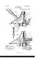
- Fig. 4 ' is a View partly in side elevation and partly in central vertical section, the view being in the same direction as Fig. 3 and the worm or cork-screw proper being inits highest position.
- Fig; 5 is a View similar to Fig. 4, the worm being, however, in its lowest, position.
- Fig. 4 is a View similar to Fig. 4, the worm being, however, in its lowest, position.
- Fig. 6 is a front elevation of the cork-extractor, the view being in the direction indicated by the arrow 00 Fig. 3.
- Fig. 7 is,a top plan of the bottle-clamping jaws at the lower end of the case or barrel of the cork-extractor, the parts above the jaws being removed by horizontal plane passing through the line 7--7, Fig. 6 and the jaws being in their position of greatest separation.
- Fig. 8 is a view partly in top plan and partly in horizontal section showing the jaws in their closed position.
- Fig. 9 is an elevation of the inner face of the lever, which actuates the clamping jaws and
- Fig. 10 is an elevation of the clamping jaws in the position illustrated in Fig. 7, the operating lever being removed to show the form and relation of the jaws.
- A, A are the two similar parts making up the hollow shell or frame of my improved cork-extractor, the two parts being connected by suitably placed transverse screws, S, S, and also preferably by an inclined plate, A forming an ornamental top or cover for a portion of the hollow shell.
- the two parts, A, A, of the shell are provided, respectively, with partialintegrally cast feet, a, a, formed approximately as shown in Fig.
- the two castings A, A are of suchshape as to leave in the bottom of the shell at the inner end of the base-plate, a, a,
- the front portion of the shell formed by the two castings, A, A is an approximately cylindrical vertical barrel in which slides freely up and down a corkscrew carrier, B, preferably formed with lateral flanges, b, slid- 7o ing in grooves, 0. in the walls of the barrel and adapted to prevent rotation of the corkscrewcarrier.
- a corkscrew carrier In this corkscrew carrier is supported a freely rotating corkscrew or worm, C, secured against longitudinal movement with reference to the carrier, 13, by means of a head, 0, lying in a suitable chamber in the carrier.
- the corkscrew passes through and conforms to a nut, D, formed with flanges, cl, lyingin the groove, a already mentioned, and adapted to permit Vertical .movement of the nut, but to prevent its rotation, the function of the not being evidently to cause the rotation of the corkscrew when the corkscrew and nut move longitudinally with relation to each other.
- a trans- "verse shaft, E preferably integral with a lever, E, and a crank, E both at right angles to the shaft, the crank being within the shell and the lever without it, and the lever being provided with a suitable handle, c.
- the crank, E is connected by a pitman, F, with the corkscrew carrier B, the latter being pro- 5 vided with a projecting ear, I), to receive one end of the pitman and the connectionof the pitman with the crank and the corkscrew carrier being by suitable transverse pivots.
- the transverse shaft, E may be connected rpo withthe lever, E',,and crank, E in any desired manner, instead of being formed integrally therewith, but I prefer to form all of said parts in a single piece, the lever and shaft being connected by a curved portion as shown in Fig. 1, and the shaft being brought into proper relation to the part, A, of the shell by passing the free end of the lever outwardthrough the shaft-opening in the shell before the parts of the shell are fastened together.
- the two parts, A, A, of the shell are provided with corresponding forwardly project ing lugs, a a and between these lugs is pivoted a lever, H, provided at its lower end with curved or cam-shaped fingers, h, h, engaging lugs, g 9 on the front ends of the jaws, G, G, the shape of the fingers, h, h, beingsuch that when the lever, H, is in the position shown in Fig. 3, its upper end being at its rearward limit of movement, the fingers are in such relation to the lugs, g g as to permit the greatest possible separation of the front or free ends of the jaws G, G, as illustrated in Fig. 7.
- a lug, H On the inner end face of the lever, H, is formed a lug, H, of such shape and so placed as to pass through an opening, a", in the front wall of the shell, A, A, and to lie immediately above the nut, D, when the lever, H, is in its normal position and the jaws, G, G, are in their position of greatest separation.
- the lug, I-I lies above the nut, D, it forms a stop preventing upward movement of the nut, but when the lever, H, is thrown forward to the position shown in Figs.
- Fig. 2 The position of the parts of the cork-extractor at the beginning of the operation of drawing a cork from a bottle is illustrated in Fig. 2, the lever, E, being thrown back, the corkscrew being in its highest position and the lever, 1 1, being thrown forward to draw the jaws, G, G, together and clamp the neck of the bottle so as to hold it in place beneath the barrel and the corkscrew therein.
- the first movement of the operation of drawing the cork is that of throwing the lever, E, forward in the direction indicated by the arrow thereon in Fig. 4, the result of this movement being to press the corkscrew downward through the nut, D, and into the cork, the corkscrew being rotated by means of the nut in its downward movement.
- the lever, E is again swung forward pressing the corkscrew carrier, the corkscrew, the nut and the cork downward together, the lug, ll, being pressed outward as the nut, D, passes it and being pressed inward by the spring immediately thereafter to form a stop for holding the nut in its lowest position.
- the movement of the lever, E is again reversed and the corkscrew carrier and corkscrew are raised to their highest position, the corkscrew being rotated in this upward movement by means of the stationary nut and being thus withdrawn from the cork.
- a simple wire stripping device attached to the extractor and adapted to strip the wires from the cork and neck of the bottle is a great convenience and such a device is shown in Figs. 1 and 2, K being a plate of sheet-metal fastened to the rear face of the shell, A, A, and formed with a downwardly projecting point, K, adapted to engage the wire.
- the position of the bottle during the stripping of the wire is shown in dotted lines in Fig. 1, the side of the neck of the bottle being in contact with the point of the stripper and the neck being supported upon a shoulder, 70, at the upper end of the plate, A which forms part of the shell as hereinbefore set forth.
- the shoulder, 70 forms a fulcrum upon which the bottle neck may be rotated and drawn away from the stripper, thereby drawing th wire from the bottle neck and cork.
- a cork-extractor the combination with asuitable case, a corkscrew rotating and moving longitudinally in the case, and means for reciprocating the corkscrew longitudinally, of a non-rotatable nut encircling the corkscrew and having a limited longitudinal movement, and alever movableindependentlyof the corkscrew operating mechanism and provided with a lug adapted when in one position to form a stop for said nut and prevent the longitudinal movement thereof.
- a cork-extractor the combination with a suitable case, a corkscrew rotating and movinglongitudinally in the case and means for reciprocating the corkscrew longitudinally, of a non-rotatable nut encircling the corkscrew and havinga limited longitudinal movement, a movable stop lying normally in the'path of movement of the nut, a spring exerting its force upon said stop and tending to hold it.
- a rotatable cork-screw moving longitudinally therein and means for reciprocating the corkscrew longitudinally, of a non-rotatable nut encircling the corkscrew and having a limited longitudinal movement, co-acting jaws adapted to clasp the neck of a bottle in the path of movement of the corkscrew, a lever connected withsaid jaws and adapted to draw them together, and a mov-- ing longitudinally therein and means for 116* ciprocating the corkscrew longitudinally, of a non-rotatable nut encircling the corkscrew and having a limited longitudinal movemerit, co-acting jaws adapted to clasp the neck of a bottle in the path of movement of the corkscrew, and a lever connected with said jaws and adapted to draw them together, the lever being provided with a lug'adapted, in one position of the lever, to engage said nut and prevent longitudinal movement thereof, and
Description
(No Model.) 4 Sheets-Sheet 1.
U. MORGAN.
- GORK EXTRAGTOR.
No. 532,575. PatentedjJan. 15, 1895..
(No Model.) 4 Sheets-Sheet 2.
.0. MORGAN. CORK EXTRAGTOR.
No. 532,575. Patented Jan. 15, 1895.
1: it i! k ,2 :w W1 1J7; Mfl "G a l 4 I l W I (No Model.) *4 sheets- -sheet '3.
0. MORGAN.
CORK EXTRAGTOR.
5. Patented Jan. 15,1895.
"WM 2 11v 'illiill Mi i g v m x v l l f H5 III 7 mum M .4 w "Illllllllllll I i 1! J 1. J" h (No Model.) 4 Sheets-Sheet 4.;
0 MORGAN GORK' EXTRAGTOR.
Patented Jan. 15, 1895.
. Extractors, of which the following is a speciextractor, the View being in the direction in- CHARLES MORGAN, OF
FREEPORT, ILLINOIS.
CORK-EXTRACTOR.
SPECIFICATION forming part of Letters Iatent No. 532,575, dated January 15, 1895.
Application filed September 12, 189A- Serial No. 22,801- (No model.)
.To all whom it may concern:
Be it known that I, CHARLES MORGAN, a citizen of the United States of America, residing at Freeport, in the county of Stephenson and State of Illinois, have invented cer-' tain new and useful Improvements in Corkfication.
My invention relates to improvements in cork-extractors and is fully described and explained in thisspecification and shown in the accompanying drawings, in which Figure 1 is a top plan of a cork-extractor embodying my improvements. Fig. 2 is a partial rear elevation thereof, the View being in the direction indicated by the arrow, 00, Fig. 1. Fig. 3 is a side elevation ofthe corkdicated by the arrow ac Fig. 1. Fig. 4 'is a View partly in side elevation and partly in central vertical section, the view being in the same direction as Fig. 3 and the worm or cork-screw proper being inits highest position. Fig; 5 is a View similar to Fig. 4, the worm being, however, in its lowest, position. Fig. 6 is a front elevation of the cork-extractor, the view being in the direction indicated by the arrow 00 Fig. 3. Fig. 7 is,a top plan of the bottle-clamping jaws at the lower end of the case or barrel of the cork-extractor, the parts above the jaws being removed by horizontal plane passing through the line 7--7, Fig. 6 and the jaws being in their position of greatest separation. Fig. 8 is a view partly in top plan and partly in horizontal section showing the jaws in their closed position. Fig. 9 is an elevation of the inner face of the lever, which actuates the clamping jaws and Fig. 10 is an elevation of the clamping jaws in the position illustrated in Fig. 7, the operating lever being removed to show the form and relation of the jaws.
In the views, A, A are the two similar parts making up the hollow shell or frame of my improved cork-extractor, the two parts being connected by suitably placed transverse screws, S, S, and also preferably by an inclined plate, A forming an ornamental top or cover for a portion of the hollow shell. The two parts, A, A, of the shell are provided, respectively, with partialintegrally cast feet, a, a, formed approximately as shown in Fig.
l and constituting together a base-plate having screw-holes for fastening it to the top of a counter. 1 The two castings A, A, are of suchshape as to leave in the bottom of the shell at the inner end of the base-plate, a, a,
an opening adapted to permit the insertion of one of the jaws of a clamp, A having the usual set screw, S, by means of which the shell may be fastened to the edge of a counter, it being objectionable or impossible in some cases to fasten the base-plate to the counter by means of screws passing through the screw-holes.
The front portion of the shell formed by the two castings, A, A, is an approximately cylindrical vertical barrel in which slides freely up and down a corkscrew carrier, B, preferably formed with lateral flanges, b, slid- 7o ing in grooves, 0. in the walls of the barrel and adapted to prevent rotation of the corkscrewcarrier. In this corkscrew carrier is supported a freely rotating corkscrew or worm, C, secured against longitudinal movement with reference to the carrier, 13, by means of a head, 0, lying in a suitable chamber in the carrier. The corkscrew passes through and conforms to a nut, D, formed with flanges, cl, lyingin the groove, a already mentioned, and adapted to permit Vertical .movement of the nut, but to prevent its rotation, the function of the not being evidently to cause the rotation of the corkscrew when the corkscrew and nut move longitudinally with relation to each other.
In the .walls of the shell at a suitable distance from the worm, O, isjournaled a trans- "verse shaft, E, preferably integral with a lever, E, and a crank, E both at right angles to the shaft, the crank being within the shell and the lever without it, and the lever being provided with a suitable handle, c. The crank, E is connected by a pitman, F, with the corkscrew carrier B, the latter being pro- 5 vided with a projecting ear, I), to receive one end of the pitman and the connectionof the pitman with the crank and the corkscrew carrier being by suitable transverse pivots.
The transverse shaft, E, may be connected rpo withthe lever, E',,and crank, E in any desired manner, instead of being formed integrally therewith, but I prefer to form all of said parts in a single piece, the lever and shaft being connected by a curved portion as shown in Fig. 1, and the shaft being brought into proper relation to the part, A, of the shell by passing the free end of the lever outwardthrough the shaft-opening in the shell before the parts of the shell are fastened together.
Immediately beneath the lower end of the barrel of the shell or frame are two co-acting bottle-clamping jaws, G, G, swinging about a common joint formed by rearwardly projectrespectively, these cars being cylindrical segments and being partially encircled and held in place by two, dependent flanges, G, G, formed on the castings, A, A, respectively, and constituting a partial socket for the ears. The inner faces of the jaws, G, G, are provided with rubber cushions, g, whose ends lie in the slightly undercut walls of the jaws and are thus secured against accidental displacement and the front ends of the jaws are normally held apart orin the position shown in Fig. 5, by means of a spring, 3, whose free ends rest in suitable openings in the inner faces of the jaws.
The two parts, A, A, of the shell are provided with corresponding forwardly project ing lugs, a a and between these lugs is pivoted a lever, H, provided at its lower end with curved or cam-shaped fingers, h, h, engaging lugs, g 9 on the front ends of the jaws, G, G, the shape of the fingers, h, h, beingsuch that when the lever, H, is in the position shown in Fig. 3, its upper end being at its rearward limit of movement, the fingers are in such relation to the lugs, g g as to permit the greatest possible separation of the front or free ends of the jaws G, G, as illustrated in Fig. 7. When, however, the upper end of the lever, H, is swung forward or in the direction indicated by the arrow thereon in Fig. 3,the fingers, 71, h, are moved approximately upward about the pivot of the lever and force the lugs, g 9 toward each other, thereby bringing the jaws toward or into the position shown in Fig. 8. The force of the spring, 3, is sufficient to hold the front ends of the jaws normally in their position of greatest separation and, consequently, to hold the lever, H, in the position shown in Fig. 3, the lower portion of the lever being in contact with the front of the barrel of the case.
On the inner end face of the lever, H, is formed a lug, H, of such shape and so placed as to pass through an opening, a", in the front wall of the shell, A, A, and to lie immediately above the nut, D, when the lever, H, is in its normal position and the jaws, G, G, are in their position of greatest separation. When the lug, I-I, lies above the nut, D, it forms a stop preventing upward movement of the nut, but when the lever, H, is thrown forward to the position shown in Figs. 4.- and 5, for the purpose of drawing the jaws G, G, together, the lug, H, is withdrawn from its ing co-acting ears, g, g, formed on the jaws position above the nut and leaves the latter free to rise in the barrel in which it lies.
The position of the parts of the cork-extractor at the beginning of the operation of drawing a cork from a bottle is illustrated in Fig. 2, the lever, E, being thrown back, the corkscrew being in its highest position and the lever, 1 1, being thrown forward to draw the jaws, G, G, together and clamp the neck of the bottle so as to hold it in place beneath the barrel and the corkscrew therein. The first movement of the operation of drawing the cork is that of throwing the lever, E, forward in the direction indicated by the arrow thereon in Fig. 4, the result of this movement being to press the corkscrew downward through the nut, D, and into the cork, the corkscrew being rotated by means of the nut in its downward movement. As soon as the corkscrew fully enters the cork, the movement of the lever, B is reversed and the corkscrew carrier and corkscrew are raised again to the position shown in Fig. 4, but as the cork is immediatetly beneath the nut, the latter rises with the corkscrew, which thus moves upward without rotation and draws the cork from the bottle. Upon the extraction of the cork the bottle is removed from the jaws, G, G, and the lever-,H, is released and is pressed by the spring, 8, to its normal position, in which the lug H, passes through the opening, a", and projects into the path of the nut, D,. The lever, E, is again swung forward pressing the corkscrew carrier, the corkscrew, the nut and the cork downward together, the lug, ll, being pressed outward as the nut, D, passes it and being pressed inward by the spring immediately thereafter to form a stop for holding the nut in its lowest position. As soon as the nut reaches its lowest position, the movement of the lever, E, is again reversed and the corkscrew carrier and corkscrew are raised to their highest position, the corkscrew being rotated in this upward movement by means of the stationary nut and being thus withdrawn from the cork.
In the use of a cork-extractor, a simple wire stripping device attached to the extractor and adapted to strip the wires from the cork and neck of the bottle is a great convenience and such a device is shown in Figs. 1 and 2, K being a plate of sheet-metal fastened to the rear face of the shell, A, A, and formed with a downwardly projecting point, K, adapted to engage the wire. The position of the bottle during the stripping of the wire is shown in dotted lines in Fig. 1, the side of the neck of the bottle being in contact with the point of the stripper and the neck being supported upon a shoulder, 70, at the upper end of the plate, A which forms part of the shell as hereinbefore set forth. The shoulder, 70, forms a fulcrum upon which the bottle neck may be rotated and drawn away from the stripper, thereby drawing th wire from the bottle neck and cork.
The device above described for gripping the neck of the bottle and holding it in position while the cork is drawn meets all the requirements of actual use and is a great addition to the practical effectiveness of the cork-extractor. The operation of the jaws, G, G, by means of the cam-shaped fingers on the lever, H, insures their symmetrical movement, so that the neck of thebottle and the cork within it are always held in a central position with relation to the barrel of the cork-extractor, and the manipulation of the jaws by the hand of the operator,independently of the mechanism for extracting the cork afiords a perfect adjustment, adapting the jaws to grasp firmly a bottle neck of any size within necessary limits. So far as I know these two features of operation are not found in any prior de' vice of this class.
I claim as new and desire to secure by Letters Patent- 1. In a cork-extractor, the combination with a suitable case, a corkscrew rotating and moving longitudinally therein and means for imparting reciprocal longitudinal movement to the corkscrew, of a non-rotating nut encircling the corkscrew and having a limited longitudinal movement in the case and a'movable stop adapted to be moved into or out of the path of the nut, by means independent of the corkscrew-operating mechanism and when in one position to prevent longitudinal movement of the nut.
2. In a cork-extractor, the combination with asuitable case, a corkscrew rotating and moving longitudinally in the case, and means for reciprocating the corkscrew longitudinally, of a non-rotatable nut encircling the corkscrew and having a limited longitudinal movement, and alever movableindependentlyof the corkscrew operating mechanism and provided with a lug adapted when in one position to form a stop for said nut and prevent the longitudinal movement thereof.
3. In a cork-extractor, the combination with a suitable case, a corkscrew rotating and movinglongitudinally in the case and means for reciprocating the corkscrew longitudinally, of a non-rotatable nut encircling the corkscrew and havinga limited longitudinal movement, a movable stop lying normally in the'path of movement of the nut, a spring exerting its force upon said stop and tending to hold it.
a suitable case, a rotatable cork-screw moving longitudinally therein and means for reciprocating the corkscrew longitudinally, of a non-rotatable nut encircling the corkscrew and having a limited longitudinal movement, co-acting jaws adapted to clasp the neck of a bottle in the path of movement of the corkscrew, a lever connected withsaid jaws and adapted to draw them together, and a mov-- ing longitudinally therein and means for 116* ciprocating the corkscrew longitudinally, of a non-rotatable nut encircling the corkscrew and having a limited longitudinal movemerit, co-acting jaws adapted to clasp the neck of a bottle in the path of movement of the corkscrew, and a lever connected with said jaws and adapted to draw them together, the lever being provided with a lug'adapted, in one position of the lever, to engage said nut and prevent longitudinal movement thereof, and
the movement of the lever in drawing the jaws together being adapted to withdraw said lug from engagement with the nut.-
6. The combination with the case, the corkscrew supported therein and means for rotating and reciprocating the screw, of the pivoted jaws, G, G, adapted to clasp the neck of a bottle and formed at their free ends with lugs, g g the swinging lever, H, formed with symmetrical cams or fingers, h, h, impinging upon the lugs, and means substantially as shown and described for pressing, apart the free ends of the jaws, G,
7. In a cork-extractor, the combination with the two-part case, A, A, and the corkscrew carrier, B, moving longitudinally therein, of the transverse shaft, E, lever, E, and crank, E formed in a single. piece and the pitman F, connecting the crank and corkscrew carrier, the lever, shaft and crank being formed and the parts being adaptedto be assembled substantially as described.
8. Ina corkscrew carrier, the combination with the two-part shell, A, A, having the de-' pendent flanges, G, G, of the rotatable and longitudinally movable corkscrew within the shell and means for operating the same, the co-acting jaws, G, G, formed with ears, g, g, lying between the flanges, G, G, and means substantially as shown and described for operating said jaws to clamp the neck of a bottle in the path of movement of the corkscrew. 1
CHARLES MORGAN.
Witnesses:
RUDOLPH LABUDDE, AUGUST WEBER.
Publications (1)
| Publication Number | Publication Date |
|---|---|
| US532575A true US532575A (en) | 1895-01-15 |
Family
ID=2601344
Family Applications (1)
| Application Number | Title | Priority Date | Filing Date |
|---|---|---|---|
| US532575D Expired - Lifetime US532575A (en) | Cork-extractor |
Country Status (1)
| Country | Link |
|---|---|
| US (1) | US532575A (en) |
Cited By (4)
| Publication number | Priority date | Publication date | Assignee | Title |
|---|---|---|---|---|
| US4253351A (en) * | 1979-07-09 | 1981-03-03 | Hallen Company | Cork extractor |
| US5934160A (en) * | 1998-01-20 | 1999-08-10 | Faye Fong Chen | Cork extractor |
| KR100885369B1 (en) | 2005-12-23 | 2009-02-26 | 주식회사 엘지화학 | New leveler for leveling and cu electro deposition by using the same |
| US9181072B2 (en) | 2010-12-20 | 2015-11-10 | True Fabrications, Inc. | Foil cutting cork extractor |
-
0
- US US532575D patent/US532575A/en not_active Expired - Lifetime
Cited By (4)
| Publication number | Priority date | Publication date | Assignee | Title |
|---|---|---|---|---|
| US4253351A (en) * | 1979-07-09 | 1981-03-03 | Hallen Company | Cork extractor |
| US5934160A (en) * | 1998-01-20 | 1999-08-10 | Faye Fong Chen | Cork extractor |
| KR100885369B1 (en) | 2005-12-23 | 2009-02-26 | 주식회사 엘지화학 | New leveler for leveling and cu electro deposition by using the same |
| US9181072B2 (en) | 2010-12-20 | 2015-11-10 | True Fabrications, Inc. | Foil cutting cork extractor |
Similar Documents
| Publication | Publication Date | Title |
|---|---|---|
| US532575A (en) | Cork-extractor | |
| US2769978A (en) | Clip applying devices | |
| US2583479A (en) | Automatic clamp for pipe bending machines | |
| US546747A (en) | Cork-extractor | |
| US1141267A (en) | Bottle-capping machine. | |
| US931325A (en) | Tire-upsetter. | |
| US474788A (en) | Device for extracting corks | |
| US909671A (en) | Machine for removing from and replacing gears, &c., upon shafts. | |
| US920008A (en) | Cork-puller. | |
| US1412153A (en) | Car mover | |
| US444755A (en) | To the bottlers | |
| US728520A (en) | Cork-puller. | |
| US784501A (en) | Umbrella-holder. | |
| US1432199A (en) | Ejecting device for key-forming machines | |
| US797246A (en) | Corking-machine. | |
| US659626A (en) | Riveting-machine. | |
| US334061A (en) | Cork-extractor | |
| US441422A (en) | Cork-extractor | |
| US436202A (en) | Half to mtjmford d | |
| US728517A (en) | Cork-puller. | |
| US927127A (en) | Corkscrew. | |
| US1440982A (en) | Metal-bending device | |
| US1979110A (en) | Capping machine for manual and mechanical driving | |
| US1057021A (en) | Automatic cork-puller. | |
| US549607A (en) | morgan |