US772477A - Turret-lathe. - Google Patents
Turret-lathe. Download PDFInfo
- Publication number
- US772477A US772477A US4236301A US1901042363A US772477A US 772477 A US772477 A US 772477A US 4236301 A US4236301 A US 4236301A US 1901042363 A US1901042363 A US 1901042363A US 772477 A US772477 A US 772477A
- Authority
- US
- United States
- Prior art keywords
- shaft
- turret
- lathe
- slide
- belt
- Prior art date
- Legal status (The legal status is an assumption and is not a legal conclusion. Google has not performed a legal analysis and makes no representation as to the accuracy of the status listed.)
- Expired - Lifetime
Links
Images


Classifications
-
- B—PERFORMING OPERATIONS; TRANSPORTING
- B23—MACHINE TOOLS; METAL-WORKING NOT OTHERWISE PROVIDED FOR
- B23Q—DETAILS, COMPONENTS, OR ACCESSORIES FOR MACHINE TOOLS, e.g. ARRANGEMENTS FOR COPYING OR CONTROLLING; MACHINE TOOLS IN GENERAL CHARACTERISED BY THE CONSTRUCTION OF PARTICULAR DETAILS OR COMPONENTS; COMBINATIONS OR ASSOCIATIONS OF METAL-WORKING MACHINES, NOT DIRECTED TO A PARTICULAR RESULT
- B23Q15/00—Automatic control or regulation of feed movement, cutting velocity or position of tool or work
-
- Y—GENERAL TAGGING OF NEW TECHNOLOGICAL DEVELOPMENTS; GENERAL TAGGING OF CROSS-SECTIONAL TECHNOLOGIES SPANNING OVER SEVERAL SECTIONS OF THE IPC; TECHNICAL SUBJECTS COVERED BY FORMER USPC CROSS-REFERENCE ART COLLECTIONS [XRACs] AND DIGESTS
- Y10—TECHNICAL SUBJECTS COVERED BY FORMER USPC
- Y10T—TECHNICAL SUBJECTS COVERED BY FORMER US CLASSIFICATION
- Y10T29/00—Metal working
- Y10T29/51—Plural diverse manufacturing apparatus including means for metal shaping or assembling
- Y10T29/5179—Speed controller
Definitions
- the present invention has particular reference to the driving mechanism of thelathe.
- the invention consists in the peculiar and novel construction and the combination of the parts whereby the speed of the revolving work and the feed of the several tools may be adjusted and automatically controlled, as will be more fully set forth hereinafter.
- the object of this invention is to provide means for adjusting the speed and feed for 3 each of thetools carried on the turret of a turret-lathe and when adjusted to reproduce a series of duplicates ofthe work by automatically controlling the speed and the feed.
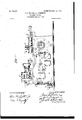
- Figure l is a side view of our improved lathe, showing a turret tool-holder supported on the tool-slide. the head of the lathe.
- Fig. 3 is an end view as seen from the slide end of the lathe. 'Fig.
- Fig. 4 is a longitudinal vertical section of the head 4 of the lathe, showing two pairs of cone-pulleys and the mechanismfor automatically controlling the belts on the-cone-pulleys.
- Fig. 5 is a transverse sectional view ofgthe head,
- Fig. 6 is a Fig; 2 is an end view of 1 detail View illustrating the gearing for driving the spindle at different speeds.
- A indicates the Supportclosed sides and provided with doors to secure convenient access to the interior; B, the headstock; 0, the main tool-slide; D, the turret tool-holder, and E a cross-slide.
- Power is applied, usually by a belt, tothe pulley b, secured to the shaft 6 of the lower cone-pulley 6 which is connected by a belt 6 with the uppercOne-pulley b, on the shaft of which the pinion b engages with the gear 6, and this engages with the gear 6 secured to the back shaftb whereby rotary motion is imparted to the back shaft.
- On the back shaft 6 are two gears 6 and 6 mounted loose on the shaft. One of these gears is provided with a coupling 6 and the other with the coupling 6 and these gears engage, respec-' spindle 6
- the clutch b is connected with the back shaft by a spline and groove.
- the clutch When connected with the coupling 5, it drives the spindle 6 through the larger gear Z), and when the clutch is connected with the coupling 6 it-drives the spindle through the smaller gear 6
- the clutch is operated by the rock-shaft 6, having at one end an arm or fork engaging with a circumferential groove on the clutch, and on the other end the operating-lever 5 is secured.
- the rock-shaft 6 is provided with a collar bearing against the inner end of the sleeveb".
- the clampinglever b is in screw-thread engagement with I the threaded end Of the shaft 6 and serves to clamp the same in the adjusted position.
- the Spindle 6 may be rotated at highor'low speed. Both of these speeds are under the control of the cone-pulleys b and 6*, by which the speed may be adtomatically varied.
- the mechanism foroperating the main toolslide C and turret D is driven from the pul- .ley 6 on the shaft 6 by means of a belt connecting the pulley 6 with-the pulley L on ing-base of the lathe, preferably formed with tivelygwiththe gear 6 and the gear 6 on the the shaft of the upper back cone-pulley 71 connected by the belt 5 with thelower back cone-pulley 6
- a graduated driving-pulley 6 is secured to the shaft of the lower back cone-pulley b and is connected by a belt with the graduated-driving-pulley 11 on the shaft 6 which extends to the mechanism operating the main tool-slide C and imparts motion to the same.
- the mechanism operated by the shaft I) may be of any one of the kinds heretofore used to convert the rotary motion of the shaft Z2 into the desired reciprocating movement of the main tool-slide and the turret.
- the variation of the speed of rotation of the work is secured through the armf pivotally supported near the heel f on a fixed part of the machine.
- the heel f has a roller which bears against the edges of the plates f on the left-hand side of the drum f.
- the coiled spring f serves to maintain the contact between the heel f and the plates f.
- the arm f is provided with the segmental gear f engaging with the pinion f, on the shaft of which is secured the gear j, which engages with the rack-bar f one end of which is secured to the shipper f, by which the belt 5 connecting the cone-pulleys b and 5, is controlled.
- the spindle 6 is driven through the cone-pulleys I) and b and the work is rotated by the spindle tthe speed of rotation is controlled through the shipper mechanism above described by the edges of the plates f on the left of the drum f.
- the normal position of the belts b and 6 is shown in the drawings near the ends of the cone-pulleys.
- the normal position of the belts may be at any point between the opposite ends of the cone-pulleys required to give the desired normal speed of the lathe-spindle and the normal feed or speed of reciprocation to the main tool-slide.
- the shaft supporting the pinion f and the gear f engaging with the rack-barf, and the shaft supporting the pinion f, on which shaft the gear engaging with the rack-bar sccured to the shipper f is also supported are both extended through the wall of the sunporting-base.
- the ends of these shafts are squared or formed to [it a wrench.
- the ratchet-wheels f f are secured on the ends of the two shafts, and the pawlsff"" are pivoted to the base A to engage with the ratchet-wheels f, as is shown in Fig. 1.
- the ratchet-wheelsf f are preferably provided with twenty-four teeth, and index-marks are placed on the ratchet-wheels.
- the mechanism shown in dotted lines in Fig. 1 may be employed, it comprising a worm (ir on the shaft 6 which meshes with a wormwheel H on the same shaft with the pinion /1, that meshes with a gear I, having a crank 1', that engages a lever K to vibrate the latter, the lever K being connected by a pitman c with the tool-slide.
- a worm ir on the shaft 6 which meshes with a wormwheel H on the same shaft with the pinion /1, that meshes with a gear I, having a crank 1', that engages a lever K to vibrate the latter, the lever K being connected by a pitman c with the tool-slide.
- a lathe the combination of a part to be moved at variable speeds, belt-gearing for imparting motion to said part, a belt-shipper, a rack and gear for moving said shipper, a pinion connected with the gear, a lever having a rack meshing with the pinion, and a cam for operating the lever.
Description
No. 772,477. PATENTEDOGT. 18, 1904. J. G. POTTER & J. JOHNSTON.
TURRET LATHE. v APPLICATION FILED JAN. 7. 1901.
4 SHEETS-SHEET 1.
no MODEL.
No. 772,477. PATENTEID OCT. 18, 1904. J. 0. POTTER & J; JOHNSTON.
TURRET LATHE. 1
APPLICATION FILED JAN. 7. 1901.
I 4 SHEETS-SHEET 2 N0 MODEL.
' wz TNIEEEE .m YEN 5E5 N0.772,477. I PAT-ENTED 00'1 .'1s,1904.
J. 0. POTTER & J. JOHNSTON.
TURRET LATHE. APPLICATION rILEn'JAN. 7, 1901.
4 SHEETS-SHEET 3- N0 MODEL.
5 555: 7 I INZIZIINZ' TTQHNEY:
No. 772,477. PATENTED OCT. 18,1904.
J. 0 POTTER & J. JOHNSTON.
TU-RRBT LATHE.
APPLICATION FILED JAN. 'I. 1901.
N0 menu 4 SHEBTS-SHEET 4.
. up If a u n wz rmzzssrs .rrb amzys UNITED STATES Patented October 18, I904.
JAMES c. POTTER AND JOHN JOHNSTON, OFPAWTUOI ET, RHODE ISLAND, ASSIGNORS TO POTTER AND JOHNSTON MACHINE COMPANY, OF PAW- T OKET, RHODE ISLAND, A CORPORATION OF RHODE ISLAND.
TURRET-LATHE.
' SPECIFICATION forming part of Letters Patent No. 772,477, dated. Oetober 18, 1904.
Application filed January 7, 1901. Serial No. Z$2,363.. (No model.) i I I To all whom it may concern.- Be it known that we, JAMES C. POTTER, a citizen of the United States, and JOHN J OHNSTON, a subject of the King of Great Britain, both 5 residing at Pawtucket, inthe county of Providence and State of Rhode Island, have invented a new and useful Improvement in Turret: Lathes, of which the following is a specification. I This invention has reference to an improvement in metal-working lathes in which the work is supported and rotated by the headstock and is operated on by a series of tools.
\ The present invention has particular reference to the driving mechanism of thelathe.
The invention consists in the peculiar and novel construction and the combination of the parts whereby the speed of the revolving work and the feed of the several tools may be adjusted and automatically controlled, as will be more fully set forth hereinafter. p In turret-lathes six tools are usually supported in the turret and successively presented to the work. Each tool requires to secure 5. the best work a specific feed of the tooljand also the specific speed of the work'best adapted to the tool. The object of this invention is to provide means for adjusting the speed and feed for 3 each of thetools carried on the turret of a turret-lathe and when adjusted to reproduce a series of duplicates ofthe work by automatically controlling the speed and the feed. Figure l is a side view of our improved lathe, showing a turret tool-holder supported on the tool-slide. the head of the lathe. Fig. 3 is an end view as seen from the slide end of the lathe. 'Fig.
4 is a longitudinal vertical section of the head 4 of the lathe, showing two pairs of cone-pulleys and the mechanismfor automatically controlling the belts on the-cone-pulleys. Fig. 5 is a transverse sectional view ofgthe head,
showing the two cone-pulleys for driving thehead-spindle and the two rear cone-pulleys for operating the tool-slide and also the Shipper connections for varying the Speed of the head-spindle and the tool-slide. Fig. 6 is a Fig; 2 is an end view of 1 detail View illustrating the gearing for driving the spindle at different speeds.
Similar marks of reference indicate corresponding parts in all the figures.
In the drawings, A indicates the Supportclosed sides and provided with doors to secure convenient access to the interior; B, the headstock; 0, the main tool-slide; D, the turret tool-holder, and E a cross-slide.
Power is applied, usually by a belt, tothe pulley b, secured to the shaft 6 of the lower cone-pulley 6 which is connected by a belt 6 with the uppercOne-pulley b, on the shaft of which the pinion b engages with the gear 6, and this engages with the gear 6 secured to the back shaftb whereby rotary motion is imparted to the back shaft. On the back shaft 6 are two gears 6 and 6 mounted loose on the shaft. One of these gears is provided with a coupling 6 and the other with the coupling 6 and these gears engage, respec-' spindle 6 The clutch b is connected with the back shaft by a spline and groove. When connected with the coupling 5, it drives the spindle 6 through the larger gear Z), and when the clutch is connected with the coupling 6 it-drives the spindle through the smaller gear 6 The clutch is operated by the rock-shaft 6, having at one end an arm or fork engaging with a circumferential groove on the clutch, and on the other end the operating-lever 5 is secured. The rock-shaft 6 is provided with a collar bearing against the inner end of the sleeveb". The clampinglever b is in screw-thread engagement with I the threaded end Of the shaft 6 and serves to clamp the same in the adjusted position. By this arrangement the Spindle 6 may be rotated at highor'low speed. Both of these speeds are under the control of the cone-pulleys b and 6*, by which the speed may be adtomatically varied. I p
The mechanism foroperating the main toolslide C and turret D is driven from the pul- .ley 6 on the shaft 6 by means of a belt connecting the pulley 6 with-the pulley L on ing-base of the lathe, preferably formed with tivelygwiththe gear 6 and the gear 6 on the the shaft of the upper back cone-pulley 71 connected by the belt 5 with thelower back cone-pulley 6 A graduated driving-pulley 6 is secured to the shaft of the lower back cone-pulley b and is connected by a belt with the graduated-driving-pulley 11 on the shaft 6 which extends to the mechanism operating the main tool-slide C and imparts motion to the same.
The mechanism operated by the shaft I) may be of any one of the kinds heretofore used to convert the rotary motion of the shaft Z2 into the desired reciprocating movement of the main tool-slide and the turret.
With the mechanism used to operate the main tool-slide we connect the shaft F, so that the same will make one revolution during the time required to use all the tools in the turret. With a six-sided turret the shaft F will make one-sixth (1;) of a revolution during one reriiprocation of the turret and the main toolsli e.
On the shaft F is secured the drum f, and on the peripheral surface are adjustably secured two sets of plates f. f. The outwardprojecting edges of these plates f f are shaped to correspond with the variations of the speed of rotation of the work on the lefthand side of the drum f and the variations of the speed of the main tool-slide and turret on the right-hand side of the drum during one reciprocation of the main tool-slide.
The variation of the speed of rotation of the work is secured through the armf pivotally supported near the heel f on a fixed part of the machine. The heel f has a roller which bears against the edges of the plates f on the left-hand side of the drum f. The coiled spring f serves to maintain the contact between the heel f and the plates f. The arm f is provided with the segmental gear f engaging with the pinion f, on the shaft of which is secured the gear j, which engages with the rack-bar f one end of which is secured to the shipper f, by which the belt 5 connecting the cone-pulleys b and 5, is controlled. As the spindle 6 is driven through the cone-pulleys I) and b and the work is rotated by the spindle tthe speed of rotation is controlled through the shipper mechanism above described by the edges of the plates f on the left of the drum f.
The plates f on the right of the drum f control, through the arm f and the pinion f, the rack-bar connected with the shipper f, by which the belt 6 is guided, and the variation of the speed of the shaft Z) and through the same the feed of the tool-supporting turret are controlled.
The normal position of the belts b and 6 is shown in the drawings near the ends of the cone-pulleys. The normal position of the belts may be at any point between the opposite ends of the cone-pulleys required to give the desired normal speed of the lathe-spindle and the normal feed or speed of reciprocation to the main tool-slide. To secure this end, the shaft supporting the pinion f and the gear f engaging with the rack-barf, and the shaft supporting the pinion f, on which shaft the gear engaging with the rack-bar sccured to the shipper f is also supported, are both extended through the wall of the sunporting-base. The ends of these shafts are squared or formed to [it a wrench. The ratchet-wheels f f are secured on the ends of the two shafts, and the pawlsff"" are pivoted to the base A to engage with the ratchet-wheels f, as is shown in Fig. 1.
As the cone-pulleys are, as shown in the drawings, of such length as to allow an adjustment of the driving-belts of twenty-four inches, the ratchet-wheelsf f are preferably provided with twenty-four teeth, and index-marks are placed on the ratchet-wheels. By this construction and arrangement the normal position of the belts on the cone-pulleys may be accurately adjusted from the outside.
For reciprocating the main tool-slide O the mechanism shown in dotted lines in Fig. 1 may be employed, it comprising a worm (ir on the shaft 6 which meshes with a wormwheel H on the same shaft with the pinion /1, that meshes with a gear I, having a crank 1', that engages a lever K to vibrate the latter, the lever K being connected by a pitman c with the tool-slide. The details of this mechanism need not be shown and described herein, as the same appear in our Patent No. 735,583, dated August 4:, 1903, to which reference may be made for a full understanding of the particular construction of said mechanism.
We have shown in the drawings the construction of the parts and their relations to each other in the (by us at this time) preferred form, but do not wish to confine ourselves to the exact construction of the parts and relations to each other as shown.
Having thus described our invention, we claim as new and desire to secure by Letters Patent 1. In a lathe, the combination of a part to be moved at variable speeds, belt-gearing for imparting motion to said part, a belt-shipper, a rack and gear for moving said shipper, and a cam-actuated lever for moving the gear.
2. In a lathe, the combination of a part to be moved at variable speeds, belt-gearing for imparting motion to said part, a belt-shipper, a rack and gear for moving said shipper, a pinion connected with the gear, a lever having a rack meshing with the pinion, and a cam for operating the lever.
3. In a lathe, the combination of a spindle, a tool-slide, belt-gearing for driving the spindle at variable speeds, belt-gearing for moving the slide at varying speeds, and an automatic belt-shipping mechanism for each of said belt-gearings.
4. In a lathe, the combination of a spindle,
spindle, one part of said belt-gearing being on i said driving-shaft, a tool-slide, a variablespeed beltgearing for moving said slide,
means for imparting motion from the drivingbelts of said belt-gearings. V
In testimony whereof We have signed our shaft to said second variable-speed b'elt-gear-v 'ing, andmeans for automatically shifting the names to this specification in the presence of a two subscribing Witnesses.
JAMES C. POTTER.
-- JOHN JOHNSTON.
Witnesses:
B. M. SIMMs, J. A. MILLER, Jr.
Priority Applications (1)
| Application Number | Priority Date | Filing Date | Title |
|---|---|---|---|
| US4236301A US772477A (en) | 1901-01-07 | 1901-01-07 | Turret-lathe. |
Applications Claiming Priority (1)
| Application Number | Priority Date | Filing Date | Title |
|---|---|---|---|
| US4236301A US772477A (en) | 1901-01-07 | 1901-01-07 | Turret-lathe. |
Publications (1)
| Publication Number | Publication Date |
|---|---|
| US772477A true US772477A (en) | 1904-10-18 |
Family
ID=2840962
Family Applications (1)
| Application Number | Title | Priority Date | Filing Date |
|---|---|---|---|
| US4236301A Expired - Lifetime US772477A (en) | 1901-01-07 | 1901-01-07 | Turret-lathe. |
Country Status (1)
| Country | Link |
|---|---|
| US (1) | US772477A (en) |
Cited By (1)
| Publication number | Priority date | Publication date | Assignee | Title |
|---|---|---|---|---|
| US2659020A (en) * | 1950-11-01 | 1953-11-10 | Cone Automatic Mach Co Inc | Mechanism for adjustable correlating tool feed with rate of cutting of machine tools |
-
1901
- 1901-01-07 US US4236301A patent/US772477A/en not_active Expired - Lifetime
Cited By (1)
| Publication number | Priority date | Publication date | Assignee | Title |
|---|---|---|---|---|
| US2659020A (en) * | 1950-11-01 | 1953-11-10 | Cone Automatic Mach Co Inc | Mechanism for adjustable correlating tool feed with rate of cutting of machine tools |
Similar Documents
| Publication | Publication Date | Title |
|---|---|---|
| US1115972A (en) | Automatic turret-lathe. | |
| US772477A (en) | Turret-lathe. | |
| US809594A (en) | Self-acting multispindle-machine. | |
| US699613A (en) | Machine for finishing metal articles. | |
| US2354266A (en) | Machine tool rapid traverse mechanism | |
| US593622A (en) | Machine foe drilling and tapping metal castings | |
| US942843A (en) | Gearing. | |
| US703660A (en) | Boring-machine. | |
| US341207A (en) | Metal turning lathe | |
| US615146A (en) | Lathe | |
| US376408A (en) | Machine for counterboring and tapping nuts | |
| US1356020A (en) | Metal-working machine | |
| US1136719A (en) | Screw-machine. | |
| US1112209A (en) | Driving mechanism for multispindle machines. | |
| US807634A (en) | Planer. | |
| US735583A (en) | Lathe. | |
| US659844A (en) | Boring and turning machine. | |
| US629874A (en) | Engine-lathe. | |
| US601580A (en) | Vertical planer | |
| USRE5996E (en) | Improvement in machines for cutting and shaping metals | |
| US468183A (en) | shellenback | |
| US416517A (en) | taylor | |
| US639888A (en) | Turret-lathe. | |
| US1510135A (en) | Machine tool | |
| US649504A (en) | Turning-lathe. |