US9120195B2 - Wheel assembly and method for making same - Google Patents
Wheel assembly and method for making same Download PDFInfo
- Publication number
- US9120195B2 US9120195B2 US12/709,986 US70998610A US9120195B2 US 9120195 B2 US9120195 B2 US 9120195B2 US 70998610 A US70998610 A US 70998610A US 9120195 B2 US9120195 B2 US 9120195B2
- Authority
- US
- United States
- Prior art keywords
- wheel
- grind
- flange surface
- bolts
- bearing
- Prior art date
- Legal status (The legal status is an assumption and is not a legal conclusion. Google has not performed a legal analysis and makes no representation as to the accuracy of the status listed.)
- Expired - Fee Related, expires
Links
Images


Classifications
-
- B—PERFORMING OPERATIONS; TRANSPORTING
- B23—MACHINE TOOLS; METAL-WORKING NOT OTHERWISE PROVIDED FOR
- B23C—MILLING
- B23C3/00—Milling particular work; Special milling operations; Machines therefor
- B23C3/13—Surface milling of plates, sheets or strips
-
- B—PERFORMING OPERATIONS; TRANSPORTING
- B23—MACHINE TOOLS; METAL-WORKING NOT OTHERWISE PROVIDED FOR
- B23C—MILLING
- B23C1/00—Milling machines not designed for particular work or special operations
- B23C1/08—Milling machines not designed for particular work or special operations with a plurality of vertical working-spindles
-
- B—PERFORMING OPERATIONS; TRANSPORTING
- B24—GRINDING; POLISHING
- B24B—MACHINES, DEVICES, OR PROCESSES FOR GRINDING OR POLISHING; DRESSING OR CONDITIONING OF ABRADING SURFACES; FEEDING OF GRINDING, POLISHING, OR LAPPING AGENTS
- B24B1/00—Processes of grinding or polishing; Use of auxiliary equipment in connection with such processes
-
- B—PERFORMING OPERATIONS; TRANSPORTING
- B24—GRINDING; POLISHING
- B24B—MACHINES, DEVICES, OR PROCESSES FOR GRINDING OR POLISHING; DRESSING OR CONDITIONING OF ABRADING SURFACES; FEEDING OF GRINDING, POLISHING, OR LAPPING AGENTS
- B24B5/00—Machines or devices designed for grinding surfaces of revolution on work, including those which also grind adjacent plane surfaces; Accessories therefor
- B24B5/36—Single-purpose machines or devices
- B24B5/44—Single-purpose machines or devices for grinding rims of vehicle wheels, e.g. for bicycles
-
- B—PERFORMING OPERATIONS; TRANSPORTING
- B24—GRINDING; POLISHING
- B24B—MACHINES, DEVICES, OR PROCESSES FOR GRINDING OR POLISHING; DRESSING OR CONDITIONING OF ABRADING SURFACES; FEEDING OF GRINDING, POLISHING, OR LAPPING AGENTS
- B24B9/00—Machines or devices designed for grinding edges or bevels on work or for removing burrs; Accessories therefor
- B24B9/02—Machines or devices designed for grinding edges or bevels on work or for removing burrs; Accessories therefor characterised by a special design with respect to properties of materials specific to articles to be ground
- B24B9/04—Machines or devices designed for grinding edges or bevels on work or for removing burrs; Accessories therefor characterised by a special design with respect to properties of materials specific to articles to be ground of metal, e.g. skate blades
-
- B—PERFORMING OPERATIONS; TRANSPORTING
- B60—VEHICLES IN GENERAL
- B60B—VEHICLE WHEELS; CASTORS; AXLES FOR WHEELS OR CASTORS; INCREASING WHEEL ADHESION
- B60B27/00—Hubs
- B60B27/0078—Hubs characterised by the fixation of bearings
-
- B—PERFORMING OPERATIONS; TRANSPORTING
- B23—MACHINE TOOLS; METAL-WORKING NOT OTHERWISE PROVIDED FOR
- B23C—MILLING
- B23C2215/00—Details of workpieces
- B23C2215/08—Automotive parts
- B23C2215/085—Wheels
-
- B—PERFORMING OPERATIONS; TRANSPORTING
- B23—MACHINE TOOLS; METAL-WORKING NOT OTHERWISE PROVIDED FOR
- B23C—MILLING
- B23C2220/00—Details of milling processes
- B23C2220/08—Milling with the axis of the tool perpendicular to the workpiece axis
-
- B—PERFORMING OPERATIONS; TRANSPORTING
- B60—VEHICLES IN GENERAL
- B60B—VEHICLE WHEELS; CASTORS; AXLES FOR WHEELS OR CASTORS; INCREASING WHEEL ADHESION
- B60B2310/00—Manufacturing methods
- B60B2310/20—Shaping
- B60B2310/232—Shaping by milling
-
- B—PERFORMING OPERATIONS; TRANSPORTING
- B60—VEHICLES IN GENERAL
- B60B—VEHICLE WHEELS; CASTORS; AXLES FOR WHEELS OR CASTORS; INCREASING WHEEL ADHESION
- B60B2310/00—Manufacturing methods
- B60B2310/20—Shaping
- B60B2310/234—Shaping by grinding
-
- B—PERFORMING OPERATIONS; TRANSPORTING
- B60—VEHICLES IN GENERAL
- B60B—VEHICLE WHEELS; CASTORS; AXLES FOR WHEELS OR CASTORS; INCREASING WHEEL ADHESION
- B60B2320/00—Manufacturing or maintenance operations
- B60B2320/10—Assembling; disassembling
-
- Y—GENERAL TAGGING OF NEW TECHNOLOGICAL DEVELOPMENTS; GENERAL TAGGING OF CROSS-SECTIONAL TECHNOLOGIES SPANNING OVER SEVERAL SECTIONS OF THE IPC; TECHNICAL SUBJECTS COVERED BY FORMER USPC CROSS-REFERENCE ART COLLECTIONS [XRACs] AND DIGESTS
- Y10—TECHNICAL SUBJECTS COVERED BY FORMER USPC
- Y10T—TECHNICAL SUBJECTS COVERED BY FORMER US CLASSIFICATION
- Y10T29/00—Metal working
- Y10T29/49—Method of mechanical manufacture
- Y10T29/49481—Wheel making
- Y10T29/49492—Land wheel
- Y10T29/49496—Disc type wheel
-
- Y—GENERAL TAGGING OF NEW TECHNOLOGICAL DEVELOPMENTS; GENERAL TAGGING OF CROSS-SECTIONAL TECHNOLOGIES SPANNING OVER SEVERAL SECTIONS OF THE IPC; TECHNICAL SUBJECTS COVERED BY FORMER USPC CROSS-REFERENCE ART COLLECTIONS [XRACs] AND DIGESTS
- Y10—TECHNICAL SUBJECTS COVERED BY FORMER USPC
- Y10T—TECHNICAL SUBJECTS COVERED BY FORMER US CLASSIFICATION
- Y10T29/00—Metal working
- Y10T29/49—Method of mechanical manufacture
- Y10T29/49481—Wheel making
- Y10T29/49492—Land wheel
- Y10T29/49538—Tire making
-
- Y—GENERAL TAGGING OF NEW TECHNOLOGICAL DEVELOPMENTS; GENERAL TAGGING OF CROSS-SECTIONAL TECHNOLOGIES SPANNING OVER SEVERAL SECTIONS OF THE IPC; TECHNICAL SUBJECTS COVERED BY FORMER USPC CROSS-REFERENCE ART COLLECTIONS [XRACs] AND DIGESTS
- Y10—TECHNICAL SUBJECTS COVERED BY FORMER USPC
- Y10T—TECHNICAL SUBJECTS COVERED BY FORMER US CLASSIFICATION
- Y10T409/00—Gear cutting, milling, or planing
- Y10T409/30—Milling
- Y10T409/304144—Means to trim edge
-
- Y—GENERAL TAGGING OF NEW TECHNOLOGICAL DEVELOPMENTS; GENERAL TAGGING OF CROSS-SECTIONAL TECHNOLOGIES SPANNING OVER SEVERAL SECTIONS OF THE IPC; TECHNICAL SUBJECTS COVERED BY FORMER USPC CROSS-REFERENCE ART COLLECTIONS [XRACs] AND DIGESTS
- Y10—TECHNICAL SUBJECTS COVERED BY FORMER USPC
- Y10T—TECHNICAL SUBJECTS COVERED BY FORMER US CLASSIFICATION
- Y10T409/00—Gear cutting, milling, or planing
- Y10T409/30—Milling
- Y10T409/30868—Work support
- Y10T409/309016—Work support with work holder or guide
- Y10T409/309072—Work support with work holder or guide including cutter limited to rotary motion
Definitions
- the present invention relates generally to an apparatus and a method for reducing lateral run-out of a wheel-hub assembly and, more specifically, a method and an apparatus for machining the rotor-mounting flange surface of the hub.
- a typical automotive vehicle is equipped with disc brake systems for the purpose of stopping the vehicle.
- These disc brake systems are located at the front axle wheel assemblies and/or at the rear wheel assembly.
- Each wheel assembly typically includes a wheel hub, a rotor and a bearing.
- the bearing may further engage a knuckle that in turn may be connected to the vehicle.
- the disc brake rotor is comprised of a circular metal disc having opposed braking surfaces that are clamped by the brake pads to exert a braking effect.
- the rotor is attached to a wheel hub.
- Performance of the braking system is related to the dimensional characteristics of the rotor and the wheel hub surface abutting the rotor. Any run-out variation in the wheel hub surface will cause lateral run-out or lateral deflection in the rotor. Lateral disc run-out refers to a lateral deviation of the planar surface of a rotor along a plane perpendicular to the longitudinal axis of rotation of the rotor. Because the rotor is designed to operate in a precise plane normal to the axis of the wheel, even slight run-out variations of the wheel hub is problematic.
- the radial run-out of the outer edges of the braking surfaces need to be controlled to ensure that the brake pads engage as much of the available rotor-braking surface as possible without overlapping the edges of the rotor. If run-out is not controlled it can cause premature failure of the brake lining due to uneven wear which requires premature replacement of the brake lining at an increased expense. Further, problems due to run-out include, brake judder, steering wheel “nibble” and pedal pulses felt by the user, and warped rotors which result in brake noise and uneven stopping. However, manufacturers have faced difficulties in achieving enhanced control over these tolerances due to the influence of several factors.
- One factor that frequently contributes to lateral run-out is variation in the processes that are used to machine the flange surface of the wheel hub.
- the outer and inner flange surfaces of the wheel hub may be individually machined causing uneven deviation of the planar surface of the wheel hub.
- Another factor that contributes to run-out is the stack-up of the individual components in a wheel assembly, i.e., their combined tolerances. While the tolerances of each part can be reduced when they are separately machined, when the parts are assembled, the combined tolerances stack up, causing run-out that is still relatively significant. Tolerance stacking may also be caused by variation in the turning processes that are used to machine the flange surface, when the wheel hub is individually machined, in an effort to make it flat with respect to the rotor. Further, the installation and press condition of the wheel bolts, the assembly process of the wheel assembly, and improperly pre-loaded bearings, can all cause misalignment of the hub surface with respect to the rotor and thus cause unacceptable run-out.
- Lateral run-out may also be caused by the insertion and/or press-fitting of the wheel bolts to the flange after the flange surface of the wheel hub has been finished or machined.
- the force causes the peripheral areas immediately around the wheel bolts to deform on the flange surface. Consequently, this deformation causes the surface of the flange to deform and deviate from the necessary planar surface of the wheel hub, causing lateral run-out.
- the process of pressing or assembling the hub to the bearing is another possible factor that causes lateral run out.
- additional run-out variation may be introduced to the rotor mounting face of the hub. Additionally, removal of the bearing and/or reassembling the bearing to the wheel hub after machining the wheel hub can re-introduce lateral run-out variation.
- the present invention provides an apparatus and a method for manufacturing a wheel hub to reduce lateral run-out.
- a wheel hub having a flange portion with an outer flange surface and an inner flange surface is provided.
- a plurality of wheel bolts are connected to the wheel hub, and the wheel hub is connected to a bearing.
- a grind wheel is then applied to the inner flange surface and outer flange surface to minimize run-out of the flange portion.
- the grind wheel includes a channel configured to allow clearance of the wheel bolts during rotation of the grind wheel.
- FIG. 1 is a perspective view of a portion of a wheel hub assembly engaged with a mill cutter.
- FIG. 2 is a perspective view of a wheel hub assembly including a knuckle.
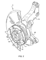
- FIG. 3 is a perspective view of a portion of a wheel hub assembly engaged with a mill cutter.
- FIG. 4 is a perspective view of a portion of a wheel hub assembly engaged with a grind wheel.
- FIG. 5 is a perspective view of a portion of a wheel hub assembly engaged with a grind wheel.
- FIG. 6 is a cross-sectional view of a portion of a wheel hub assembly engaged with a grind wheel.
- FIGS. 1 and 2 illustrate a wheel hub assembly 1 .
- the assembly 1 may include a variety of components, including a wheel hub 4 , bearing 5 , and knuckle 16 .
- the wheel hub 4 may have a flange face 12 and a pilot portion 6 .
- the pilot portion 6 extends generally outward from the flange face 12 so as to allow a rotor to be guided and affixed to the wheel hub assembly as known to one of ordinary skill in the art.
- the knuckle 16 may have a generally circular bore 18 formed therein and a plurality of outwardly extending appendages or legs 20 that are capable of attachment to the vehicle through a plurality of apertures formed in the plurality of legs 20 , as is known in the art.
- the bearing 5 may be press-fit into the bore 18 of the knuckle 16 .
- the bearing 5 may be press-fit with or without a snap ring, or may be held in place with a nut, or secured by other methods known in the art.
- a portion of the bearing 5 may be bolted to the knuckle 16 or integrally formed with the knuckle 16 .
- an inner portion of the bearing 5 may be integrally formed with the wheel hub.
- a plurality of respective wheel bolts 3 may be attachable to the wheel hub 4 .
- the wheel bolts 3 are attached to the flange face 12 in a predetermined pattern, such as equidistantly spaced, and on the same pitch circle diameter.
- the wheel bolts 3 are oriented with the threaded ends extending outwardly so as to connect a rotor and an associated wheel onto the wheel hub 4 as commonly known in the skill of the art.
- the flange face 12 may have a relief channel 8 machined therein.
- the relief channel 8 may divide the flange face 12 into an outer flange surface 7 and an inner flange surface 9 .
- the relief channel 8 is turned into the flange face 12 so that the plurality of the wheel bolts 3 are positioned in the relief channel 8 .
- the wheel hub 4 may be positioned on the bearing 5 .
- the bearing 5 is not limited to being positioned as illustrated in the figures and may, for example, secure about and/or attach about the inside diameter of the wheel hub 4 , the outside diameter of the wheel hub 4 and/or therebetween.
- the bearing 5 may be any bearing type as known to one of ordinary skill in the art, including but not limited to a single row, a double row, a ball, a roller and/or the like.
- the bearing 5 may be integrated with the wheel hub 4 .
- the bearing 5 is used in the final wheel assembly 1 such that the bearing 5 is not detached from and/or reassembled with the wheel hub 4 .
- the bearing 5 is used in the wheel assembly 1 that is attachable and/or securable to and/or secured to, for example, a vehicle.
- the present invention provides an apparatus and a method for machining the flange face 12 after the bearing 5 is attached to and/or integrated with the wheel hub 4 .
- the wheel hub 4 may be secured to the bearing 5 so that the wheel hub 4 can rotate with respect to the bearing 5 .
- the wheel hub 4 and bearing 5 may rotate with respect to the knuckle 16 .
- the wheel hub 4 may be affixed or mounted onto the bearing 5 in a variety of wheel hub/bearing configurations as known to one of ordinary skill in the art.
- the wheel hub assembly 1 is machined to flatten the outer flange surface 7 and the inner flange surface 9 that will contact a rotor, and thus minimize any lateral run-out.
- the machining process flattens the inner flange surface 9 and the outer flange surface 7 such that surfaces 7 , 9 are parallel with respect to each other.
- the machining process finishes the flange surfaces 7 , 9 such that the flange surfaces 7 , 9 are co-planar.
- the use of grind wheel process accomplishes the machining of the flange face 12 . Both processes, however, may occur after the wheel bolts 3 and/or the bearing 5 are attached or secured to the wheel hub 4 .
- FIGS. 3 and 5 illustrate rotational directions for certain components of the wheel hub assembly and components used for the finishing thereof. It will be appreciated that the rotational direction of each component is not limited to the direction of rotation illustrated. Rather, each denoted components may rotate in any direction as required.
- FIG. 3 illustrates a milling process for the flange face 12 and wheel hub assembly 1 .
- the wheel hub 4 is situated on the bearing 5 , allowing the wheel hub 4 to rotate about an axis determined by the bearing 5 .
- the wheel hub 4 is positioned on the bearing 5 so as to allow the flange face 12 to engage an inner mill cutter 2 and an outer mill cutter 10 protruding from a machine, such as a lathe.
- the inner mill cutter 2 and the outer mill cutter 10 are stationary and each consists of a cutting end, but individually rotate about an axis determined by the tool and it's bearing. The cutting end of the inner mill cutter 2 engages the inner flange surface 9 of the flange face 12 .
- the cutting end of the outer mill cutter 10 engages the outer flange surface 7 of the flange face 12 .
- one of the mill cutters 2 , 10 may be used to machine the inner flange surface 9 and/or the outer flange surface 7 .
- the milling process may occur as the wheel hub 4 rotates on the bearing 5 in a clockwise motion.
- the mill cutters 2 , 10 move from a storage position and engage the flange surfaces 7 , 9 as described above.
- the outer mill cutter 10 and/or the inner mill cutter 2 moves radially in and out as the hub wheel 4 turns, milling and finishing the flange surfaces 7 , 9 . This process of finishing reduces lateral run-out.
- an alternate embodiment for refinishing the flange face 12 is a grinding process.
- the grinding process involves use of a grind wheel 11 .
- the grind wheel 11 may be constructed from an abrasive material that may be, for example, boron, diamond, or any other abrasive and immalleable material known to one of ordinary skill of the art.
- the grind wheel 11 is a singular cylindrical apparatus that may consist of an inner lip 13 and an outer lip 14 .
- the inner lip 13 has a shape that corresponds with the inner flange surface 9 .
- the outer lip 14 and the outer flange surface 7 have corresponding shapes.
- Located in between the inner lip 13 and outer lip 14 is a channel 15 .
- the channel 15 and the relief channel 8 also have corresponding shapes.
- the purpose of the channel 15 is to allow the wheel bolts 3 of the wheel hub 4 to pass or clear within the grind wheel 11 while the grind wheel 11 engages and finishes the flange surfaces 7 , 9 .
- the grind wheel 11 is described as having both an inner lip and outer lip, it will be appreciated that other configurations may be used.
- the grind wheel 11 may comprise a single lip configured to engage either the outer flange surface 7 or the inner flange surface 9 .
- the grind wheel 11 serves as a machining apparatus for the purpose of finishing the flange face 12 .
- the open face of grind wheel 11 is placed on the top of the wheel hub 4 so that the grind wheel 11 engages flange face 12 .
- the inner lip 13 is aligned along the inner flange surface 9 .
- the outer lip 14 is aligned along the outer flange surface 7 . This arrangement allows the outer lip 14 to cup the wheel bolts 3 so that the wheel bolts 3 terminate within the channel 15 of the grind wheel 11 .
- FIGS. 5 and 6 illustrate the grinding process of the present invention.
- the grind wheel 11 is placed on top of the wheel hub 4 as described above. As the wheel hub 4 rotates in a clockwise direction about the axis of the bearing 5 , the grind wheel 11 is rotated in the counterclockwise direction.
- the rotations of the wheel hub 4 and the grind wheel 11 are not limited to clockwise and counterclockwise rotations respectively, but, preferably are in opposite directions as known to one of ordinary skill of the art.
- the inner flange surface 9 and outer flange surface 7 are finished by the friction created against the inner lip 13 and outer lip 14 of the grind wheel.
- the grind wheel 11 rotates at a higher rate of speed than the wheel hub 4 and in an opposite direction with respect to the wheel hub 4 .
- the rotational axis of the bearing 5 and the rotational axis of the of the grind wheel 11 are not coaxial during the grinding process, e.g., while grinding the inner and outer flange surfaces 7 , 9 .
- the rotational axis of the grind wheel 11 may be angled relative to the axis of rotation of the bearing 5 .
- the rotational axis of the grind wheel 11 is angled away from the rotational axis of the bearing 5 , in the direction from the bearing 5 to the grind wheel 11 .
- the lips 13 , 14 of the grind wheel have surfaces that are grinding surfaces that form an acute angle with the plane normal to the axis of rotation of the grind wheel 11 .
- the portion of the surfaces of the lips 13 , 14 that contact with an inner or outer flange surface for grinding the flange surfaces are preferably oriented perpendicular to the axis of rotation of the bearing 5 .
- a grinding surface of a lip 13 , 14 may have a width and a circumference.
- a first portion of the grinding surface of the lip 13 , 14 contacts a flange surface 7 , 9 along the width of the lip and a second portion of the lip is located above the flange surface 7 , 9 and has no contact with the flange surface along the width of the lip.
- the number of bolts having a length entirely in the annular channel at any moment preferably is one or less, such as illustrated in FIGS. 5 and 6 .
Abstract
Description
Claims (20)
Priority Applications (2)
| Application Number | Priority Date | Filing Date | Title |
|---|---|---|---|
| US12/709,986 US9120195B2 (en) | 2009-02-20 | 2010-02-22 | Wheel assembly and method for making same |
| US14/809,742 US20150367426A1 (en) | 2009-02-20 | 2015-07-27 | Wheel assembly, and apparatus and method for making same |
Applications Claiming Priority (2)
| Application Number | Priority Date | Filing Date | Title |
|---|---|---|---|
| US20810209P | 2009-02-20 | 2009-02-20 | |
| US12/709,986 US9120195B2 (en) | 2009-02-20 | 2010-02-22 | Wheel assembly and method for making same |
Related Child Applications (1)
| Application Number | Title | Priority Date | Filing Date |
|---|---|---|---|
| US14/809,742 Continuation US20150367426A1 (en) | 2009-02-20 | 2015-07-27 | Wheel assembly, and apparatus and method for making same |
Publications (2)
| Publication Number | Publication Date |
|---|---|
| US20100257737A1 US20100257737A1 (en) | 2010-10-14 |
| US9120195B2 true US9120195B2 (en) | 2015-09-01 |
Family
ID=42634240
Family Applications (2)
| Application Number | Title | Priority Date | Filing Date |
|---|---|---|---|
| US12/709,986 Expired - Fee Related US9120195B2 (en) | 2009-02-20 | 2010-02-22 | Wheel assembly and method for making same |
| US14/809,742 Abandoned US20150367426A1 (en) | 2009-02-20 | 2015-07-27 | Wheel assembly, and apparatus and method for making same |
Family Applications After (1)
| Application Number | Title | Priority Date | Filing Date |
|---|---|---|---|
| US14/809,742 Abandoned US20150367426A1 (en) | 2009-02-20 | 2015-07-27 | Wheel assembly, and apparatus and method for making same |
Country Status (2)
| Country | Link |
|---|---|
| US (2) | US9120195B2 (en) |
| WO (1) | WO2010096765A1 (en) |
Cited By (2)
| Publication number | Priority date | Publication date | Assignee | Title |
|---|---|---|---|---|
| US20150367426A1 (en) * | 2009-02-20 | 2015-12-24 | Diversified Machine, Inc. | Wheel assembly, and apparatus and method for making same |
| US9440488B1 (en) * | 2016-02-08 | 2016-09-13 | Ahmed Y. A. Mothafar | Hubless wheel system for motor vehicles |
Families Citing this family (3)
| Publication number | Priority date | Publication date | Assignee | Title |
|---|---|---|---|---|
| US8801503B2 (en) | 2012-06-19 | 2014-08-12 | Gleason Cutting Tools Corporation | Grinding machine with multi-spindle grinding head |
| CN112517985A (en) * | 2020-06-09 | 2021-03-19 | 湖南思远智能装备有限公司 | Intelligent double-spindle end face milling machine for processing blade root flange face |
| CN117415685B (en) * | 2023-11-16 | 2024-03-26 | 启东海大聚龙新材料科技有限公司 | Resin sliding bearing inner ring surface polishing equipment |
Citations (59)
| Publication number | Priority date | Publication date | Assignee | Title |
|---|---|---|---|---|
| US1605173A (en) | 1923-12-07 | 1926-11-02 | Niles Bement Pond Co | Work-holding means for car-wheel lathes |
| US2891435A (en) | 1952-09-30 | 1959-06-23 | Ammco Tools Inc | Lathe |
| US3044791A (en) | 1961-05-16 | 1962-07-17 | Budd Co | Clamp chuck for workpieces |
| US3526058A (en) | 1967-06-28 | 1970-09-01 | Litton Industries Inc | Diamond roller dresser |
| US4042346A (en) | 1975-12-24 | 1977-08-16 | Norton Company | Diamond or cubic boron nitride grinding wheel with resin core |
| EP0023881A2 (en) | 1979-07-31 | 1981-02-11 | Mannesmann Kronprinz AG | Commercial-vehicle wheel for single or dual assembly |
| GB2080745A (en) | 1980-07-29 | 1982-02-10 | Barlow Peter | Adapter for caravan hub |
| EP0065127A2 (en) | 1981-05-18 | 1982-11-24 | RIV-SKF OFFICINE DI VILLAR PEROSA S.p.A | A support assembly for vehicle wheels |
| US4699431A (en) | 1986-06-26 | 1987-10-13 | General Motors Corporation | Piloted wheel assembly |
| GB2198995A (en) | 1986-12-19 | 1988-06-29 | Honda Motor Co Ltd | Vehicle wheel assembly |
| JPS6428056A (en) | 1987-07-23 | 1989-01-30 | Koyo Seiko Co | Bearing device for axle |
| US4881842A (en) | 1988-10-17 | 1989-11-21 | General Motors Corporation | Wheel bearing assembly |
| US4918872A (en) * | 1984-05-14 | 1990-04-24 | Kanebo Limited | Surface grinding apparatus |
| DE3900356A1 (en) | 1989-01-07 | 1990-07-12 | Bergische Achsen Kotz Soehne | Wheel bearing |
| US4949511A (en) * | 1986-02-10 | 1990-08-21 | Toshiba Tungaloy Co., Ltd. | Super abrasive grinding tool element and grinding tool |
| JPH0391990A (en) | 1989-09-05 | 1991-04-17 | Seiko Epson Corp | Bonding device for semiconductor device |
| US5090851A (en) | 1991-08-15 | 1992-02-25 | White Joseph P | Cutting tool for milling machines |
| US5108156A (en) | 1991-06-10 | 1992-04-28 | Bell Chris R | Rotor and hub run-out shim for automotive wheel assembly |
| US5158739A (en) | 1990-06-27 | 1992-10-27 | Framatome | Device for dismantling an irradiated component of a nuclear reactor by machining its wall |
| US5209701A (en) | 1990-12-07 | 1993-05-11 | Nikon Corporation | Hub unit bearing apparatus with improved pre-loading arrangement |
| US5257561A (en) | 1992-05-11 | 1993-11-02 | Illinois Tool Works Inc. | Tire holding fixture for tire processing machine |
| US5381630A (en) * | 1992-09-28 | 1995-01-17 | Kinner; James | Brake rotor grinding method and apparatus |
| US5398999A (en) | 1993-03-01 | 1995-03-21 | Kelsey-Hayes Company | Vehicle brake assembly and method of installation |
| JPH07164809A (en) | 1993-12-10 | 1995-06-27 | Koyo Seiko Co Ltd | Fastening structure |
| US5430926A (en) | 1994-01-03 | 1995-07-11 | Kelsey-Hayes Company | Method of producing a rotatable brake component and bearing assembly |
| US5443316A (en) | 1993-06-24 | 1995-08-22 | The Budd Company | Live spindle hub with inboard bearing retention |
| US5464233A (en) | 1993-03-08 | 1995-11-07 | Howa Machinery Ltd. | Finger chuck for use with machine tool |
| US5490720A (en) | 1994-01-27 | 1996-02-13 | Hayes Wheels International, Inc. | Vehicle wheel having a tinnerman nut clearance groove |
| US5653153A (en) | 1996-02-09 | 1997-08-05 | Greenwald; Christopher L. | On-vehicle brake lathe and alignment device therefor |
| US5680801A (en) | 1995-11-02 | 1997-10-28 | General Electric Company | Machining damper and method of using same |
| US5791976A (en) * | 1995-12-08 | 1998-08-11 | Tokyo Seimitsu Co., Ltd. | Surface machining method and apparatus |
| US5885137A (en) * | 1997-06-27 | 1999-03-23 | Siemens Aktiengesellschaft | Chemical mechanical polishing pad conditioner |
| US5884980A (en) | 1996-10-31 | 1999-03-23 | Robert Bosch Technologies Corporation | Vehicle brake and hub attachment system and method |
| US5899305A (en) | 1997-05-21 | 1999-05-04 | Varga Brakes, Inc. | Method for fabricating brake disc |
| US5915502A (en) | 1997-02-27 | 1999-06-29 | Varga North America, Inc. | Brake disc assembly and a method for fabricating brake disc |
| US5937499A (en) | 1997-12-19 | 1999-08-17 | Varga Brakes, Inc. | Machining brake disc without moment load on bearing |
| US6004196A (en) * | 1998-02-27 | 1999-12-21 | Micron Technology, Inc. | Polishing pad refurbisher for in situ, real-time conditioning and cleaning of a polishing pad used in chemical-mechanical polishing of microelectronic substrates |
| US6071180A (en) * | 1999-01-19 | 2000-06-06 | Ernst Thielenhaus Gmbh & Co. Kg | Method of surface grinding a flange surface of a wheel hub for an automotive vehicle |
| US6139405A (en) * | 1999-01-19 | 2000-10-31 | Ernst Thielenhaus Gmbh & Co. Kg | Method of making a motor-vehicle brake-disk assembly |
| US6158124A (en) | 1998-11-17 | 2000-12-12 | Varga Brakes, Inc. | Preloading & machining mounted brake disc |
| US6212981B1 (en) * | 1999-05-28 | 2001-04-10 | Simpson Industries, Inc. | Knuckle hub fixture assembly and method of using |
| US6247219B1 (en) | 1997-02-27 | 2001-06-19 | Kelsey-Hayes Company | Method for producing a vehicle hub, bearing and brake disc assembly |
| US20010029153A1 (en) * | 1992-06-03 | 2001-10-11 | Hitachi Ltd. | Rolling mill equipped with on-line roll grinding system and grinding wheel |
| US20010045770A1 (en) | 1999-05-28 | 2001-11-29 | Artz & Artz Pc | Knuckle hub assembly and method for making same |
| US6364426B1 (en) | 1998-08-05 | 2002-04-02 | Kelsey-Hayes Company | Vehicle wheel hub and bearing unit assembly and method for producing same |
| US6415508B1 (en) * | 1999-06-09 | 2002-07-09 | The Timken Company | Hub assembly having minimum runout and process for producing the same |
| US20040046440A1 (en) | 2001-12-14 | 2004-03-11 | Daniel Brinker | Knuckle hub assembly and method for making same |
| US6708589B2 (en) | 1999-05-28 | 2004-03-23 | Metaldyne Machining & Assembly Company, Inc. | Brake rotor assembly and method for making same |
| US6880898B2 (en) * | 1999-02-17 | 2005-04-19 | Nsk Ltd. | Bearing unit for wheel and manufacturing method thereof |
| US7024751B2 (en) | 2003-03-25 | 2006-04-11 | Metaldyne Company Llc | Housing and method of manufacturing said housing |
| US7047645B2 (en) * | 2000-02-23 | 2006-05-23 | Nsk Ltd. | Bearing unit for wheel and method of manufacturing the same |
| US7083504B2 (en) * | 2003-06-12 | 2006-08-01 | Koyo Seiko Co., Ltd. | Method of processing antifriction bearing unit for wheel |
| US7270037B2 (en) * | 1996-09-04 | 2007-09-18 | Pro-Cut Licensing Company, Llc | Apparatus and method for automatically compensating for lateral runout |
| US7337699B2 (en) * | 1996-09-04 | 2008-03-04 | Pro-Cut Licensing Company, Llc | Apparatus and method for automatically compensating for lateral runout |
| US20090105031A1 (en) | 2007-10-17 | 2009-04-23 | Michael Sefcik | Differential assembly and method for manufacturing same |
| US7650696B2 (en) * | 2005-03-30 | 2010-01-26 | Nsk Ltd. | Manufacturing method for bearing unit for support wheel |
| US7681478B2 (en) * | 2003-07-24 | 2010-03-23 | Hunter Engineering Company | Method and apparatus for resurfacing brake rotors |
| WO2010096765A1 (en) | 2009-02-20 | 2010-08-26 | Diversified Machine Inc. | Wheel assembly and method for making same |
| US8151434B2 (en) * | 2006-03-29 | 2012-04-10 | Jtekt Corporation | Method of grinding a brake disk mounting surface with an annular recess using an inclined grinding wheel |
-
2010
- 2010-02-22 WO PCT/US2010/024924 patent/WO2010096765A1/en active Application Filing
- 2010-02-22 US US12/709,986 patent/US9120195B2/en not_active Expired - Fee Related
-
2015
- 2015-07-27 US US14/809,742 patent/US20150367426A1/en not_active Abandoned
Patent Citations (74)
| Publication number | Priority date | Publication date | Assignee | Title |
|---|---|---|---|---|
| US1605173A (en) | 1923-12-07 | 1926-11-02 | Niles Bement Pond Co | Work-holding means for car-wheel lathes |
| US2891435A (en) | 1952-09-30 | 1959-06-23 | Ammco Tools Inc | Lathe |
| US3044791A (en) | 1961-05-16 | 1962-07-17 | Budd Co | Clamp chuck for workpieces |
| US3526058A (en) | 1967-06-28 | 1970-09-01 | Litton Industries Inc | Diamond roller dresser |
| US4042346A (en) | 1975-12-24 | 1977-08-16 | Norton Company | Diamond or cubic boron nitride grinding wheel with resin core |
| US4456308A (en) | 1979-07-31 | 1984-06-26 | Mannesmann Ag | Wheel and brake-drum configuration for vehicles |
| EP0023881A2 (en) | 1979-07-31 | 1981-02-11 | Mannesmann Kronprinz AG | Commercial-vehicle wheel for single or dual assembly |
| GB2080745A (en) | 1980-07-29 | 1982-02-10 | Barlow Peter | Adapter for caravan hub |
| EP0065127A2 (en) | 1981-05-18 | 1982-11-24 | RIV-SKF OFFICINE DI VILLAR PEROSA S.p.A | A support assembly for vehicle wheels |
| US4918872A (en) * | 1984-05-14 | 1990-04-24 | Kanebo Limited | Surface grinding apparatus |
| US4949511A (en) * | 1986-02-10 | 1990-08-21 | Toshiba Tungaloy Co., Ltd. | Super abrasive grinding tool element and grinding tool |
| US4699431A (en) | 1986-06-26 | 1987-10-13 | General Motors Corporation | Piloted wheel assembly |
| GB2198995A (en) | 1986-12-19 | 1988-06-29 | Honda Motor Co Ltd | Vehicle wheel assembly |
| US4792020A (en) | 1986-12-19 | 1988-12-20 | Honda Giken Kogyo Kabushiki Kaisha | Vehicle wheel assembly |
| JPS6428056A (en) | 1987-07-23 | 1989-01-30 | Koyo Seiko Co | Bearing device for axle |
| US4864231A (en) | 1987-07-23 | 1989-09-05 | Koyo Seiko Co., Ltd. | Bearing assembly having a wheel speed sensor |
| US4881842A (en) | 1988-10-17 | 1989-11-21 | General Motors Corporation | Wheel bearing assembly |
| DE3900356A1 (en) | 1989-01-07 | 1990-07-12 | Bergische Achsen Kotz Soehne | Wheel bearing |
| JPH0391990A (en) | 1989-09-05 | 1991-04-17 | Seiko Epson Corp | Bonding device for semiconductor device |
| US5158739A (en) | 1990-06-27 | 1992-10-27 | Framatome | Device for dismantling an irradiated component of a nuclear reactor by machining its wall |
| US5209701A (en) | 1990-12-07 | 1993-05-11 | Nikon Corporation | Hub unit bearing apparatus with improved pre-loading arrangement |
| US5108156A (en) | 1991-06-10 | 1992-04-28 | Bell Chris R | Rotor and hub run-out shim for automotive wheel assembly |
| US5090851A (en) | 1991-08-15 | 1992-02-25 | White Joseph P | Cutting tool for milling machines |
| US5257561A (en) | 1992-05-11 | 1993-11-02 | Illinois Tool Works Inc. | Tire holding fixture for tire processing machine |
| US20010029153A1 (en) * | 1992-06-03 | 2001-10-11 | Hitachi Ltd. | Rolling mill equipped with on-line roll grinding system and grinding wheel |
| US5381630A (en) * | 1992-09-28 | 1995-01-17 | Kinner; James | Brake rotor grinding method and apparatus |
| US5398999A (en) | 1993-03-01 | 1995-03-21 | Kelsey-Hayes Company | Vehicle brake assembly and method of installation |
| US5464233A (en) | 1993-03-08 | 1995-11-07 | Howa Machinery Ltd. | Finger chuck for use with machine tool |
| US5443316A (en) | 1993-06-24 | 1995-08-22 | The Budd Company | Live spindle hub with inboard bearing retention |
| JPH07164809A (en) | 1993-12-10 | 1995-06-27 | Koyo Seiko Co Ltd | Fastening structure |
| US5430926A (en) | 1994-01-03 | 1995-07-11 | Kelsey-Hayes Company | Method of producing a rotatable brake component and bearing assembly |
| US5490720A (en) | 1994-01-27 | 1996-02-13 | Hayes Wheels International, Inc. | Vehicle wheel having a tinnerman nut clearance groove |
| US5680801A (en) | 1995-11-02 | 1997-10-28 | General Electric Company | Machining damper and method of using same |
| US5791976A (en) * | 1995-12-08 | 1998-08-11 | Tokyo Seimitsu Co., Ltd. | Surface machining method and apparatus |
| US5653153A (en) | 1996-02-09 | 1997-08-05 | Greenwald; Christopher L. | On-vehicle brake lathe and alignment device therefor |
| US7337699B2 (en) * | 1996-09-04 | 2008-03-04 | Pro-Cut Licensing Company, Llc | Apparatus and method for automatically compensating for lateral runout |
| US7270037B2 (en) * | 1996-09-04 | 2007-09-18 | Pro-Cut Licensing Company, Llc | Apparatus and method for automatically compensating for lateral runout |
| US5884980A (en) | 1996-10-31 | 1999-03-23 | Robert Bosch Technologies Corporation | Vehicle brake and hub attachment system and method |
| US5915502A (en) | 1997-02-27 | 1999-06-29 | Varga North America, Inc. | Brake disc assembly and a method for fabricating brake disc |
| US6247219B1 (en) | 1997-02-27 | 2001-06-19 | Kelsey-Hayes Company | Method for producing a vehicle hub, bearing and brake disc assembly |
| US5899305A (en) | 1997-05-21 | 1999-05-04 | Varga Brakes, Inc. | Method for fabricating brake disc |
| US5885137A (en) * | 1997-06-27 | 1999-03-23 | Siemens Aktiengesellschaft | Chemical mechanical polishing pad conditioner |
| US5937499A (en) | 1997-12-19 | 1999-08-17 | Varga Brakes, Inc. | Machining brake disc without moment load on bearing |
| US6004196A (en) * | 1998-02-27 | 1999-12-21 | Micron Technology, Inc. | Polishing pad refurbisher for in situ, real-time conditioning and cleaning of a polishing pad used in chemical-mechanical polishing of microelectronic substrates |
| USRE39195E1 (en) * | 1998-02-27 | 2006-07-18 | Micron Technology, Inc. | Polishing pad refurbisher for in situ, real-time conditioning and cleaning of a polishing pad used in chemical-mechanical polishing of microelectronic substrates |
| US6364426B1 (en) | 1998-08-05 | 2002-04-02 | Kelsey-Hayes Company | Vehicle wheel hub and bearing unit assembly and method for producing same |
| US6158124A (en) | 1998-11-17 | 2000-12-12 | Varga Brakes, Inc. | Preloading & machining mounted brake disc |
| US6071180A (en) * | 1999-01-19 | 2000-06-06 | Ernst Thielenhaus Gmbh & Co. Kg | Method of surface grinding a flange surface of a wheel hub for an automotive vehicle |
| US6139405A (en) * | 1999-01-19 | 2000-10-31 | Ernst Thielenhaus Gmbh & Co. Kg | Method of making a motor-vehicle brake-disk assembly |
| US6880898B2 (en) * | 1999-02-17 | 2005-04-19 | Nsk Ltd. | Bearing unit for wheel and manufacturing method thereof |
| US20010048242A1 (en) | 1999-05-28 | 2001-12-06 | Simpson Industries, Inc. | Knuckle hub assembly and method for making same |
| US20080129106A1 (en) * | 1999-05-28 | 2008-06-05 | Daniel Brinker | Knuckle hub assembly and method for making same |
| US6634266B2 (en) | 1999-05-28 | 2003-10-21 | Simpson Industries, Inc. | Wheel hub assembly fixture |
| US20100236069A1 (en) | 1999-05-28 | 2010-09-23 | Daniel Brinker | Knuckle hub assembly and method for making same |
| US7716833B2 (en) | 1999-05-28 | 2010-05-18 | Metaldyne Chassis Products, Llc | Knuckle hub assembly and method for making same |
| US6708589B2 (en) | 1999-05-28 | 2004-03-23 | Metaldyne Machining & Assembly Company, Inc. | Brake rotor assembly and method for making same |
| US6450584B2 (en) | 1999-05-28 | 2002-09-17 | Daniel Brinker | Knuckle hub assembly and method for making same |
| US20050206221A1 (en) * | 1999-05-28 | 2005-09-22 | Daniel Brinker | Knuckle hub assembly and method for making same |
| US6485109B2 (en) | 1999-05-28 | 2002-11-26 | Simpson Industries, Inc. | Knuckle hub assembly and method for making same |
| US6212981B1 (en) * | 1999-05-28 | 2001-04-10 | Simpson Industries, Inc. | Knuckle hub fixture assembly and method of using |
| US7296332B2 (en) | 1999-05-28 | 2007-11-20 | Daniel Brinker | Brake rotor assembly and method for making same |
| US20010045770A1 (en) | 1999-05-28 | 2001-11-29 | Artz & Artz Pc | Knuckle hub assembly and method for making same |
| US6415508B1 (en) * | 1999-06-09 | 2002-07-09 | The Timken Company | Hub assembly having minimum runout and process for producing the same |
| US6702398B2 (en) * | 1999-06-09 | 2004-03-09 | The Timken Company | Hub assembly having minimum runout and process for producing the same |
| US7047645B2 (en) * | 2000-02-23 | 2006-05-23 | Nsk Ltd. | Bearing unit for wheel and method of manufacturing the same |
| US20040046440A1 (en) | 2001-12-14 | 2004-03-11 | Daniel Brinker | Knuckle hub assembly and method for making same |
| US7024751B2 (en) | 2003-03-25 | 2006-04-11 | Metaldyne Company Llc | Housing and method of manufacturing said housing |
| US7226344B2 (en) * | 2003-06-12 | 2007-06-05 | Koyo Seiko Co., Ltd. | Method of processing antifriction bearing unit for wheel |
| US7083504B2 (en) * | 2003-06-12 | 2006-08-01 | Koyo Seiko Co., Ltd. | Method of processing antifriction bearing unit for wheel |
| US7681478B2 (en) * | 2003-07-24 | 2010-03-23 | Hunter Engineering Company | Method and apparatus for resurfacing brake rotors |
| US7650696B2 (en) * | 2005-03-30 | 2010-01-26 | Nsk Ltd. | Manufacturing method for bearing unit for support wheel |
| US8151434B2 (en) * | 2006-03-29 | 2012-04-10 | Jtekt Corporation | Method of grinding a brake disk mounting surface with an annular recess using an inclined grinding wheel |
| US20090105031A1 (en) | 2007-10-17 | 2009-04-23 | Michael Sefcik | Differential assembly and method for manufacturing same |
| WO2010096765A1 (en) | 2009-02-20 | 2010-08-26 | Diversified Machine Inc. | Wheel assembly and method for making same |
Non-Patent Citations (11)
| Title |
|---|
| Corresponding U.S. Appl. No. 09/414,113, filed Oct. 8, 1999 now patented as 6,485,109. |
| Corresponding U.S. Appl. No. 09/899,772, filed Jul. 5, 2001 now patented as 6,450,584. |
| Corresponding U.S. Appl. No. 10/016,589, filed Dec. 14, 2001 now patented as 6,634,266. |
| Corresponding U.S. Appl. No. 10/658,861, filed Sep. 9, 2003 (Abandoned) published as 2004/0046440 dated Mar. 11, 2004. |
| Corresponding U.S. Appl. No. 11/012,074, filed Dec. 14, 2004 (Abandoned) published as 2005/0206221 dated Sep. 22, 2005. |
| Corresponding U.S. Appl. No. 11/413,076, filed Apr. 27, 2006 reissue application now patented 6,450,584. |
| Corresponding U.S. Appl. No. 11/998,865, filed Nov. 30, 2007 now patented as 7,716,833. |
| Corresponding U.S. Appl. No. 12/749,053, filed Mar. 29, 2010 published as 2010/0236069. |
| International Search Report/Written Opinion, PCT/US2010/024924, dated Apr. 15, 2010(Published as WO2010/096765 on Aug. 26, 2010. |
| Shevket, Cengiz R., Handwritten note to Bill Sullivan of Continental-Teves Re: U222/8 Hub and Bearing Unit Proposal, Nov. 19, 1998. |
| Shevket, Cengiz R., SKF Comparison of Taper Unit Bearing with Respect to U222 Program Requirements, E-mail, Jul. 17, 1998. |
Cited By (2)
| Publication number | Priority date | Publication date | Assignee | Title |
|---|---|---|---|---|
| US20150367426A1 (en) * | 2009-02-20 | 2015-12-24 | Diversified Machine, Inc. | Wheel assembly, and apparatus and method for making same |
| US9440488B1 (en) * | 2016-02-08 | 2016-09-13 | Ahmed Y. A. Mothafar | Hubless wheel system for motor vehicles |
Also Published As
| Publication number | Publication date |
|---|---|
| US20150367426A1 (en) | 2015-12-24 |
| WO2010096765A1 (en) | 2010-08-26 |
| US20100257737A1 (en) | 2010-10-14 |
Similar Documents
| Publication | Publication Date | Title |
|---|---|---|
| US6364426B1 (en) | Vehicle wheel hub and bearing unit assembly and method for producing same | |
| EP1200219B1 (en) | Process for producing a hub assembly having minimum runout | |
| US20150367426A1 (en) | Wheel assembly, and apparatus and method for making same | |
| US5430926A (en) | Method of producing a rotatable brake component and bearing assembly | |
| US6450584B2 (en) | Knuckle hub assembly and method for making same | |
| EP2563639B1 (en) | Apparatus for final finishing a wheel hub of a knuckle assembly and related method | |
| JP5566916B2 (en) | Outer hub barrel mounting rotor | |
| US7650696B2 (en) | Manufacturing method for bearing unit for support wheel | |
| KR100908504B1 (en) | Brake Rotor Assembly and Manufacturing Method Thereof | |
| EP1652690A2 (en) | A wheel hub of corner assembly | |
| US20050231025A1 (en) | Wheel support rolling bearing unit and manufacturing method therefor | |
| US20020066185A1 (en) | Method of machining a hub bearing unit for a wheel of a motor vehicle | |
| EP1780100B1 (en) | A method of manufacturing a steering knuckle corner assembly | |
| JP2004092830A (en) | Manufacturing method for bearing unit for wheel | |
| US20200254536A1 (en) | Wheel assembly and method for making same | |
| JP3238927B2 (en) | Device for centering rotary units | |
| WO2007029700A1 (en) | Rolling bearing unit for supporting wheel and method of producing the same | |
| US7117600B1 (en) | Process of manufacturing a corner assembly | |
| EP3900875B1 (en) | Bearing ring member production method, roller bearing production method, hub unit bearing production method, and vehicle production method | |
| CN111059175B (en) | Machining method of drum brake and drum brake | |
| EP1470936A1 (en) | Bearing unit for vehicle wheel | |
| JP2006021605A (en) | Rolling bearing unit for supporting wheel and its manufacturing method | |
| EP1470935A1 (en) | Bearing unit for vehicle wheel | |
| JP2006071057A (en) | Bearing unit for supporting wheel and its manufacturing method | |
| JP2003184918A (en) | Bearing unit for wheel attached with rotating body for brake |
Legal Events
| Date | Code | Title | Description |
|---|---|---|---|
| AS | Assignment |
Owner name: DIVERSIFIED MACHINE, INC., MICHIGAN Free format text: ASSIGNMENT OF ASSIGNORS INTEREST;ASSIGNOR:VELDMAN, ROBERT;REEL/FRAME:024724/0981 Effective date: 20100719 |
|
| AS | Assignment |
Owner name: BARCLAYS BANK PLC, AS COLLATERAL AGENT, NEW YORK Free format text: SECURITY AGREEMENT SUPPLEMENT;ASSIGNORS:DMI EDON LLC;DIVERSIFIED MACHINE MONTAGUE, INC.;DIVERSIFIED MACHINE, INC.;REEL/FRAME:025605/0448 Effective date: 20101028 |
|
| AS | Assignment |
Owner name: BMO HARRIS BANK N.A., ILLINOIS Free format text: PATENT SECURITY AGREEMENT;ASSIGNORS:DIVERSIFIED MACHINE, INC.;DMI EDON, LLC;DIVERSIFIED MACHINE MONTAGUE, INC.;REEL/FRAME:027335/0056 Effective date: 20111201 Owner name: BANK OF MONTREAL, ILLINOIS Free format text: PATENT SECURITY AGREEMENT;ASSIGNORS:DIVERSIFIED MACHINE, INC.;DMI EDON, LLC;DIVERSIFIED MACHINE MONTAGUE, INC.;REEL/FRAME:027333/0841 Effective date: 20111201 |
|
| AS | Assignment |
Owner name: DIVERSIFIED MACHINE, INC., MICHIGAN Free format text: RELEASE BY SECURED PARTY;ASSIGNOR:BARCLAYS BANK PLC;REEL/FRAME:027385/0526 Effective date: 20111201 |
|
| AS | Assignment |
Owner name: BMO HARRIS BANK N.A., ILLINOIS Free format text: PATENT SECURITY AGREEMENT;ASSIGNORS:DIVERSIFIED MACHINE, INC.;DMI EDON LLC;DIVERSIFIED MACHINE MONTAGUE, INC.;AND OTHERS;REEL/FRAME:029835/0726 Effective date: 20121221 |
|
| AS | Assignment |
Owner name: BANK OF MONTREAL, ILLINOIS Free format text: PATENT SECURITY AGREEMENT;ASSIGNORS:DIVERSIFIED MACHINE, INC.;DMI EDON LLC;DIVERSIFIED MACHINE MONTAGUE, INC.;AND OTHERS;REEL/FRAME:029839/0512 Effective date: 20121221 Owner name: DIVERSIFIED MACHINE, INC., MICHIGAN Free format text: RELEASE OF SECURITY INTEREST IN PATENTS;ASSIGNOR:BANK OF MONTREAL;REEL/FRAME:029844/0874 Effective date: 20121221 Owner name: DIVERSIFIED MACHINE MONTAGUE, INC., MICHIGAN Free format text: RELEASE OF SECURITY INTEREST IN PATENTS;ASSIGNOR:BANK OF MONTREAL;REEL/FRAME:029844/0874 Effective date: 20121221 Owner name: DMI EDON, LLC, MICHIGAN Free format text: RELEASE OF SECURITY INTEREST IN PATENTS;ASSIGNOR:BANK OF MONTREAL;REEL/FRAME:029844/0874 Effective date: 20121221 Owner name: DIVERSIFIED MACHINE MONTAGUE, INC., MICHIGAN Free format text: RELEASE OF SECURITY INTEREST IN PATENTS;ASSIGNOR:BMO HARRIS BANK N.A.;REEL/FRAME:029840/0265 Effective date: 20121221 Owner name: DIVERSIFIED MACHINE, INC., MICHIGAN Free format text: RELEASE OF SECURITY INTEREST IN PATENTS;ASSIGNOR:BMO HARRIS BANK N.A.;REEL/FRAME:029840/0265 Effective date: 20121221 Owner name: DMI EDON, LLC, MICHIGAN Free format text: RELEASE OF SECURITY INTEREST IN PATENTS;ASSIGNOR:BMO HARRIS BANK N.A.;REEL/FRAME:029840/0265 Effective date: 20121221 |
|
| AS | Assignment |
Owner name: DMI EDON LLC, MICHIGAN Free format text: RELEASE BY SECURED PARTY;ASSIGNOR:BANK OF MONTREAL;REEL/FRAME:030858/0833 Effective date: 20130723 Owner name: SMW AUTOMOTIVE, LLC, MICHIGAN Free format text: RELEASE BY SECURED PARTY;ASSIGNOR:BANK OF MONTREAL;REEL/FRAME:030858/0833 Effective date: 20130723 Owner name: DIVERSIFIED MACHINE MONTAGUE, LLC, MICHIGAN Free format text: RELEASE BY SECURED PARTY;ASSIGNOR:BANK OF MONTREAL;REEL/FRAME:030858/0833 Effective date: 20130723 Owner name: DIVERSIFIED MACHINE, INC., MICHIGAN Free format text: RELEASE BY SECURED PARTY;ASSIGNOR:BANK OF MONTREAL;REEL/FRAME:030858/0833 Effective date: 20130723 |
|
| AS | Assignment |
Owner name: BMO HARRIS BANK N.A., ILLINOIS Free format text: PATENT SECURITY AGREEMENT;ASSIGNORS:DIVERSIFIED MACHINE, INC.;DMI EDON LLC;DIVERSIFIED MACHINE MONTAGUE, LLC;AND OTHERS;REEL/FRAME:030875/0308 Effective date: 20130723 |
|
| AS | Assignment |
Owner name: U.S. BANK NATIONAL ASSOCIATION, AS COLLATERAL AGEN Free format text: SECURITY AGREEMENT;ASSIGNORS:DIVERSIFIED MACHINE, INC.;DIVERSIFIED MACHINE MONTAGUE, LLC;DMI EDON LLC;AND OTHERS;REEL/FRAME:030889/0178 Effective date: 20130723 |
|
| AS | Assignment |
Owner name: DIVERSIFIED MACHINE MONTAGUE, LLC, MICHIGAN Free format text: TERMINATION OF SECURITY INTEREST IN PATENTS;ASSIGNOR:BMO HARRIS BANK N.A.;REEL/FRAME:035223/0619 Effective date: 20150312 Owner name: SMW AUTOMOTIVE, LLC, MICHIGAN Free format text: TERMINATION OF SECURITY INTEREST IN PATENTS;ASSIGNOR:BMO HARRIS BANK N.A.;REEL/FRAME:035223/0619 Effective date: 20150312 Owner name: DMI EDON LLC, MICHIGAN Free format text: TERMINATION OF SECURITY INTEREST IN PATENTS;ASSIGNOR:BMO HARRIS BANK N.A.;REEL/FRAME:035223/0619 Effective date: 20150312 Owner name: DIVERSIFIED MACHINE, INC., MICHIGAN Free format text: TERMINATION OF SECURITY INTEREST IN PATENTS;ASSIGNOR:BMO HARRIS BANK N.A.;REEL/FRAME:035223/0619 Effective date: 20150312 |
|
| AS | Assignment |
Owner name: SMW AUTOMOTIVE, LLC, MICHIGAN Free format text: TERMINATION OF SECURITY INTEREST IN PATENTS -RELEASE OF 030889/0178;ASSIGNOR:U.S. BANK NATIONAL ASSOCIATION;REEL/FRAME:036213/0779 Effective date: 20150729 Owner name: DIVERSIFIED MACHINE MONTAGUE, LLC, MICHIGAN Free format text: TERMINATION OF SECURITY INTEREST IN PATENTS -RELEASE OF 030889/0178;ASSIGNOR:U.S. BANK NATIONAL ASSOCIATION;REEL/FRAME:036213/0779 Effective date: 20150729 Owner name: DIVERSIFIED MACHINE, INC., MICHIGAN Free format text: TERMINATION OF SECURITY INTEREST IN PATENTS -RELEASE OF 030889/0178;ASSIGNOR:U.S. BANK NATIONAL ASSOCIATION;REEL/FRAME:036213/0779 Effective date: 20150729 Owner name: DMI EDON LLC, MICHIGAN Free format text: TERMINATION OF SECURITY INTEREST IN PATENTS -RELEASE OF 030889/0178;ASSIGNOR:U.S. BANK NATIONAL ASSOCIATION;REEL/FRAME:036213/0779 Effective date: 20150729 |
|
| AS | Assignment |
Owner name: PNC BANK, NATIONAL ASSOCIATION, AS COLLATERAL AGEN Free format text: SECURITY INTEREST;ASSIGNORS:CHASSIX, INC.;DIVERSIFIED MACHINE, INC.;DIVERSIFIED MACHINE MONTAGUE, LLC;AND OTHERS;REEL/FRAME:036215/0133 Effective date: 20150729 |
|
| AS | Assignment |
Owner name: CANTOR FITZGERALD SECURITIES, AS COLLATERAL AGENT, Free format text: SECURITY INTEREST;ASSIGNORS:CHASSIX, INC.;DIVERSIFIED MACHINE, INC.;DIVERSIFIED MACHINE MONTAGUE, LLC;AND OTHERS;REEL/FRAME:036267/0933 Effective date: 20150729 |
|
| STCF | Information on status: patent grant |
Free format text: PATENTED CASE |
|
| CC | Certificate of correction | ||
| AS | Assignment |
Owner name: DMI EDON LLC, MICHIGAN Free format text: RELEASE BY SECURED PARTY;ASSIGNOR:BMO HARRIS BANK N.A.;REEL/FRAME:044087/0719 Effective date: 20171108 Owner name: SMW AUTOMOTIVE CORPORATION, MICHIGAN Free format text: RELEASE BY SECURED PARTY;ASSIGNOR:BMO HARRIS BANK N.A.;REEL/FRAME:044087/0719 Effective date: 20171108 Owner name: DIVERSIFIED MACHINE MONTAGUE, INC., MICHIGAN Free format text: RELEASE BY SECURED PARTY;ASSIGNOR:BMO HARRIS BANK N.A.;REEL/FRAME:044087/0719 Effective date: 20171108 Owner name: DIVERSIFIED MACHINE, INC., MICHIGAN Free format text: RELEASE BY SECURED PARTY;ASSIGNOR:BMO HARRIS BANK N.A.;REEL/FRAME:044087/0719 Effective date: 20171108 Owner name: SMW AUTOMOTIVE CORPORATION, MICHIGAN Free format text: RELEASE BY SECURED PARTY;ASSIGNOR:BANK OF MONTREAL;REEL/FRAME:044087/0687 Effective date: 20171108 Owner name: DIVERSIFIED MACHINE, INC., MICHIGAN Free format text: RELEASE BY SECURED PARTY;ASSIGNOR:BANK OF MONTREAL;REEL/FRAME:044087/0687 Effective date: 20171108 Owner name: DMI EDON LLC, MICHIGAN Free format text: RELEASE BY SECURED PARTY;ASSIGNOR:BANK OF MONTREAL;REEL/FRAME:044087/0687 Effective date: 20171108 Owner name: DIVERSIFIED MACHINE MONTAGUE, INC., MICHIGAN Free format text: RELEASE BY SECURED PARTY;ASSIGNOR:BANK OF MONTREAL;REEL/FRAME:044087/0687 Effective date: 20171108 |
|
| AS | Assignment |
Owner name: DIVERSIFIED MACHINE, INC., AS THE SUCCESSOR IN INT Free format text: RELEASE BY SECURED PARTY;ASSIGNOR:CANTOR FITZGERALD SECURITIES, AS COLLATERAL AGENT;REEL/FRAME:044136/0375 Effective date: 20171115 Owner name: DIVERSIFIED MACHINE MONTAGUE, LLC, MICHIGAN Free format text: RELEASE BY SECURED PARTY;ASSIGNOR:CANTOR FITZGERALD SECURITIES, AS COLLATERAL AGENT;REEL/FRAME:044136/0375 Effective date: 20171115 Owner name: SMW AUTOMOTIVE, LLC, MICHIGAN Free format text: RELEASE BY SECURED PARTY;ASSIGNOR:CANTOR FITZGERALD SECURITIES, AS COLLATERAL AGENT;REEL/FRAME:044136/0375 Effective date: 20171115 |
|
| MAFP | Maintenance fee payment |
Free format text: PAYMENT OF MAINTENANCE FEE, 4TH YEAR, LARGE ENTITY (ORIGINAL EVENT CODE: M1551); ENTITY STATUS OF PATENT OWNER: LARGE ENTITY Year of fee payment: 4 |
|
| AS | Assignment |
Owner name: ALUDYNE NORTH AMERICA, INC., MICHIGAN Free format text: CHANGE OF NAME;ASSIGNOR:DIVERSIFIED MACHINE, INC.;REEL/FRAME:050963/0299 Effective date: 20191001 |
|
| AS | Assignment |
Owner name: PNC BANK, NATIONAL ASSOCIATION, AS COLLATERAL AGEN Free format text: SECURITY INTEREST;ASSIGNORS:ALUDYNE NORTH AMERICA, INC.;ALUDYNE US LLC;ALUDYNE MONTAGUE, LLC;AND OTHERS;REEL/FRAME:051368/0071 Effective date: 20191220 |
|
| AS | Assignment |
Owner name: BLUE TORCH FINANCE LLC, AS THE COLLATERAL AGENT, NEW YORK Free format text: SECURITY INTEREST;ASSIGNORS:ALUDYNE NORTH AMERICA, INC.;ALUDYNE NORTH AMERICA LLC;REEL/FRAME:062947/0294 Effective date: 20230310 |
|
| AS | Assignment |
Owner name: ALUDYNE NORTH AMERICA, INC. (F/K/A DIVERSIFIED MACHINE, INC.), MICHIGAN Free format text: RELEASE (REEL 044455 / FRAME 0773);ASSIGNOR:JPMORGAN CHASE BANK, N.A.;REEL/FRAME:063083/0462 Effective date: 20230310 |
|
| FEPP | Fee payment procedure |
Free format text: MAINTENANCE FEE REMINDER MAILED (ORIGINAL EVENT CODE: REM.); ENTITY STATUS OF PATENT OWNER: LARGE ENTITY |
|
| LAPS | Lapse for failure to pay maintenance fees |
Free format text: PATENT EXPIRED FOR FAILURE TO PAY MAINTENANCE FEES (ORIGINAL EVENT CODE: EXP.); ENTITY STATUS OF PATENT OWNER: LARGE ENTITY |
|
| STCH | Information on status: patent discontinuation |
Free format text: PATENT EXPIRED DUE TO NONPAYMENT OF MAINTENANCE FEES UNDER 37 CFR 1.362 |
|
| FP | Lapsed due to failure to pay maintenance fee |
Effective date: 20230901 |