US9386299B2 - Reference image techniques for three-dimensional sensing - Google Patents

Reference image techniques for three-dimensional sensing Download PDF

Info

Publication number
US9386299B2
US9386299B2 US14/301,427 US201414301427A US9386299B2 US 9386299 B2 US9386299 B2 US 9386299B2 US 201414301427 A US201414301427 A US 201414301427A US 9386299 B2 US9386299 B2 US 9386299B2
Authority
US
United States
Prior art keywords
image
pattern
distance
image sensor
reference image
Prior art date
Legal status (The legal status is an assumption and is not a legal conclusion. Google has not performed a legal analysis and makes no representation as to the accuracy of the status listed.)
Active, expires
Application number
US14/301,427
Other versions
US20140285638A1 (en
Inventor
Alexander Shpunt
Dmitri Rais
Niv Galezer
Current Assignee (The listed assignees may be inaccurate. Google has not performed a legal analysis and makes no representation or warranty as to the accuracy of the list.)
Apple Inc
Original Assignee
Apple Inc
Priority date (The priority date is an assumption and is not a legal conclusion. Google has not performed a legal analysis and makes no representation as to the accuracy of the date listed.)
Filing date
Publication date
Application filed by Apple Inc filed Critical Apple Inc
Priority to US14/301,427 priority Critical patent/US9386299B2/en
Assigned to PRIMESENSE LTD. reassignment PRIMESENSE LTD. ASSIGNMENT OF ASSIGNORS INTEREST (SEE DOCUMENT FOR DETAILS). Assignors: GALEZER, NIV, RAIS, DMITRI, SHPUNT, ALEXANDER
Publication of US20140285638A1 publication Critical patent/US20140285638A1/en
Assigned to APPLE INC. reassignment APPLE INC. ASSIGNMENT OF ASSIGNORS INTEREST (SEE DOCUMENT FOR DETAILS). Assignors: PRIMESENSE LTD.
Assigned to APPLE INC. reassignment APPLE INC. CORRECTIVE ASSIGNMENT TO CORRECT THE APPLICATION # 13840451 AND REPLACE IT WITH CORRECT APPLICATION # 13810451 PREVIOUSLY RECORDED ON REEL 034293 FRAME 0092. ASSIGNOR(S) HEREBY CONFIRMS THE ASSIGNMENT. Assignors: PRIMESENSE LTD.
Application granted granted Critical
Publication of US9386299B2 publication Critical patent/US9386299B2/en
Active legal-status Critical Current
Adjusted expiration legal-status Critical

Links

Images

Classifications

    • HELECTRICITY
    • H04ELECTRIC COMMUNICATION TECHNIQUE
    • H04NPICTORIAL COMMUNICATION, e.g. TELEVISION
    • H04N13/00Stereoscopic video systems; Multi-view video systems; Details thereof
    • H04N13/20Image signal generators
    • H04N13/204Image signal generators using stereoscopic image cameras
    • H04N13/207Image signal generators using stereoscopic image cameras using a single 2D image sensor
    • H04N13/218Image signal generators using stereoscopic image cameras using a single 2D image sensor using spatial multiplexing
    • H04N13/0217
    • GPHYSICS
    • G01MEASURING; TESTING
    • G01BMEASURING LENGTH, THICKNESS OR SIMILAR LINEAR DIMENSIONS; MEASURING ANGLES; MEASURING AREAS; MEASURING IRREGULARITIES OF SURFACES OR CONTOURS
    • G01B11/00Measuring arrangements characterised by the use of optical techniques
    • G01B11/24Measuring arrangements characterised by the use of optical techniques for measuring contours or curvatures
    • G01B11/25Measuring arrangements characterised by the use of optical techniques for measuring contours or curvatures by projecting a pattern, e.g. one or more lines, moiré fringes on the object
    • G01B11/2518Projection by scanning of the object
    • GPHYSICS
    • G01MEASURING; TESTING
    • G01BMEASURING LENGTH, THICKNESS OR SIMILAR LINEAR DIMENSIONS; MEASURING ANGLES; MEASURING AREAS; MEASURING IRREGULARITIES OF SURFACES OR CONTOURS
    • G01B11/00Measuring arrangements characterised by the use of optical techniques
    • G01B11/24Measuring arrangements characterised by the use of optical techniques for measuring contours or curvatures
    • G01B11/25Measuring arrangements characterised by the use of optical techniques for measuring contours or curvatures by projecting a pattern, e.g. one or more lines, moiré fringes on the object
    • G01B11/2545Measuring arrangements characterised by the use of optical techniques for measuring contours or curvatures by projecting a pattern, e.g. one or more lines, moiré fringes on the object with one projection direction and several detection directions, e.g. stereo
    • G06K9/2036
    • GPHYSICS
    • G06COMPUTING; CALCULATING OR COUNTING
    • G06TIMAGE DATA PROCESSING OR GENERATION, IN GENERAL
    • G06T1/00General purpose image data processing
    • G06T1/0007Image acquisition
    • G06T7/0057
    • GPHYSICS
    • G06COMPUTING; CALCULATING OR COUNTING
    • G06TIMAGE DATA PROCESSING OR GENERATION, IN GENERAL
    • G06T7/00Image analysis
    • G06T7/50Depth or shape recovery
    • G06T7/521Depth or shape recovery from laser ranging, e.g. using interferometry; from the projection of structured light
    • GPHYSICS
    • G06COMPUTING; CALCULATING OR COUNTING
    • G06VIMAGE OR VIDEO RECOGNITION OR UNDERSTANDING
    • G06V10/00Arrangements for image or video recognition or understanding
    • G06V10/10Image acquisition
    • G06V10/12Details of acquisition arrangements; Constructional details thereof
    • G06V10/14Optical characteristics of the device performing the acquisition or on the illumination arrangements
    • G06V10/145Illumination specially adapted for pattern recognition, e.g. using gratings
    • H04N13/0253
    • HELECTRICITY
    • H04ELECTRIC COMMUNICATION TECHNIQUE
    • H04NPICTORIAL COMMUNICATION, e.g. TELEVISION
    • H04N13/00Stereoscopic video systems; Multi-view video systems; Details thereof
    • H04N13/20Image signal generators
    • H04N13/204Image signal generators using stereoscopic image cameras
    • H04N13/254Image signal generators using stereoscopic image cameras in combination with electromagnetic radiation sources for illuminating objects

Landscapes

  • Engineering & Computer Science (AREA)
  • Physics & Mathematics (AREA)
  • General Physics & Mathematics (AREA)
  • Computer Vision & Pattern Recognition (AREA)
  • Theoretical Computer Science (AREA)
  • Multimedia (AREA)
  • Signal Processing (AREA)
  • Artificial Intelligence (AREA)
  • Electromagnetism (AREA)
  • Optics & Photonics (AREA)
  • Length Measuring Devices By Optical Means (AREA)
  • Projection Apparatus (AREA)

Abstract

A method including providing a device that projects a pattern of coherent radiation. The method further includes capturing a reference image of the pattern using an image sensor by projecting the pattern of the coherent radiation onto a reference surface and engendering a relative motion between the reference surface and the image sensor while capturing the reference image. The method also includes storing the reference image in a memory associated with the device.

Description

CROSS-REFERENCE TO RELATED APPLICATION
This application is a division of U.S. patent application Ser. No. 12/707,678, filed Feb. 18, 2010, which claims the benefit of U.S. Provisional Patent Application 61/157,560, filed Mar. 5, 2009, which is incorporated herein by reference.
FIELD OF THE INVENTION
The present invention relates generally to imaging systems, and specifically to imaging systems using reference images for three-dimensional mapping.
BACKGROUND OF THE INVENTION
Some three-dimensional (3D) mapping systems use a reference image of a pattern projected onto a calibration surface. Examples of such systems are described in PCT Publication WO 2007/043036 to Zalevsky et al., and in PCT Publication WO 2007/105205 to Shpunt et al., both of which are incorporated herein by reference. In these types of 3D mapping systems, measured deviations from the reference image in an image of a test object allows the test object to be mapped. It is thus advantageous to use high quality reference images in the mapping systems.
The description above is presented as a general overview of related art in this field and should not be construed as an admission that any of the information it contains constitutes prior art against the present patent application.
SUMMARY OF THE INVENTION
An embodiment of the present invention provides a method, including:
providing a device that projects a pattern of coherent radiation;
capturing a reference image of the pattern using an image sensor by projecting the pattern of the coherent radiation onto a reference surface and engendering a relative motion between the reference surface and the image sensor while capturing the reference image; and
storing the reference image in a memory associated with the device.
Typically, engendering the relative motion includes connecting a motion actuator to the device and activating the motion actuator while capturing the reference image.
Alternatively or additionally, engendering the relative motion includes connecting a motion actuator to a reference object having the reference surface, and activating the motion actuator while capturing the reference image.
Engendering the relative motion may include moving the device parallel to the reference surface, moving the reference surface parallel to itself, selecting an amplitude of the relative motion so as to average out effects of secondary speckles generated at the reference surface, and/or selecting an amplitude of the relative motion in response to a resolution of the image sensor.
The device may include the image sensor, the method further including:
capturing an alternative image of the pattern projected onto the reference surface using another image sensor external to the device;
registering the reference image and the alternative image; and
producing an enhanced reference image from the registered reference image and alternative image,
wherein storing the reference image in the memory includes storing the enhanced reference image in the memory.
In a disclosed embodiment, capturing the reference image includes:
capturing a first image of the pattern while the reference surface is at a first distance from the device, and a second image of the pattern while the reference surface is at a second distance, different from the first distance, from the device; and
registering the first and second images to produce an alternative reference image,
wherein storing the reference image in the memory includes storing the alternative reference image in the memory.
In another disclosed embodiment, capturing the reference image includes:
capturing a first image of the pattern while the reference surface is at a first distance from the device, and a second image of the pattern while the reference surface is at a second distance, different from the first distance, from the device, the first and the second images being configured to be registered to produce an alternative reference image; and
storing the first and second images in the memory.
Typically, the device is configured to generate a three-dimensional (3D) map of an object by capturing a test image of the pattern on the object and measuring local transverse shifts of the pattern in the test image relative to the reference image.
The device may include the image sensor, and capturing the test image may include capturing the test image using the image sensor.
In some embodiments the image sensor has an integration time, and the reference surface is stationary as measured with respect to the integration time.
There is further provided, according to an embodiment of the present invention, a method, including:
providing a device that projects a pattern onto an object and captures an image of the pattern on the object using a first image sensor having a first optical characteristic;
capturing a reference image of the pattern using a second image sensor having a second optical characteristic enhanced with respect to the first optical characteristic, by projecting the pattern onto a reference surface;
registering the reference image in a frame of reference of the device; and
storing the reference image in a memory associated with the device.
Typically, capturing the reference image includes capturing a first image of the pattern projected onto the reference surface using the first image sensor, and capturing a second image of the pattern projected onto the reference surface using the second image sensor, and wherein registering the reference image includes registering the first and second images to produce a registered reference image, and wherein storing the reference image includes storing the registered reference image in the memory.
Typically the device includes the first image sensor, and the second image sensor is external to and separate from the device.
The pattern may be projected using incoherent radiation.
The first and second optical characteristics may include at least one of respective fields of view, respective resolutions, respective signal to noise ratios, and respective dynamic ranges.
Typically, the device is configured to generate a three-dimensional (3D) map of the object by capturing a test image of the pattern on the object and measuring local transverse shifts of the pattern in the test image relative to the reference image.
In one embodiment the method further includes generating a map of the object using the reference image and the image of the pattern on the object.
There is further provided, according to an embodiment of the present invention, a method, including:
providing a device that projects a pattern onto an object;
capturing a reference image of the pattern using an image sensor by projecting the pattern onto a reference surface located at a first distance from the image sensor and at a second distance, different from the first distance, from the image sensor;
registering the reference image in a frame of reference of the device; and
storing the reference image in a memory associated with the device.
Typically, capturing the reference image includes capturing a first image of the pattern projected onto the reference surface at the first distance using the image sensor, and capturing a second image of the pattern projected onto the reference surface at the second surface using the image sensor, and wherein registering the reference image includes registering the first and second images to produce a registered reference image, and wherein storing the reference image includes storing the registered reference image in the memory.
In a disclosed embodiment projecting the pattern includes projecting the pattern into a first field of view, and wherein the image sensor has a second field of view different from the first field of view.
The image sensor may have a field of view including a subset of the reference image.
Typically, the device is configured to generate a three-dimensional (3D) map of the object by capturing a test image of the pattern on the object and measuring local transverse shifts of the pattern in the test image relative to the reference image.
Typically, the method includes generating a map of the object using the reference image and the image of the pattern on the object.
There is further provided, according to an embodiment of the invention, apparatus, including:
a projection and imaging device including:
a projector that projects a pattern of coherent radiation; and
an image sensor that captures a reference image of the pattern of coherent radiation projected onto a reference surface; and
a processor which is configured to:
implement a relative motion between the device and the reference surface while the image sensor captures the reference image, and
store the reference image in a memory associated with the device.
There is further provided, according to an embodiment of the invention, apparatus, including:
a projection and imaging device including:
a projector that projects a pattern of radiation onto an object; and
a first image sensor having a first optical characteristic, that captures an image of the pattern on the object;
a second image sensor having a second optical characteristic enhanced with respect to the first optical characteristic and which is configured to capture a reference image of the pattern projected onto a reference surface; and
a processor that is configured to:
register the reference image in a frame of reference of the device; and
store the registered reference image in a memory associated with the device.
There is further provided, according to an embodiment of the present invention, apparatus, including:
a projection and imaging device including:
a projector that projects a pattern of radiation; and
an image sensor that captures a reference image of the pattern projected on a reference surface; and
a processor which is configured to:
generate the reference image by projecting the pattern onto the reference surface located at a first distance from the image sensor and at a second distance, different from the first distance, from the image sensor,
register the reference image in a frame of reference of the device, and
store the registered reference image in a memory associated with the device.
There is further provided, according to an embodiment of the present invention, a method, including:
providing a device that projects a pattern onto an object;
capturing a reference image of the pattern using an image sensor by projecting the pattern onto a reference surface which is oriented with respect to the image sensor to have a first region of the reference surface a first distance from the image sensor and to have a second region of the reference surface a second distance, different from the first distance, from the image sensor;
registering the reference image in a frame of reference of the device; and
storing the reference image in a memory associated with the device.
Typically, the reference surface is planar and is oriented non-orthogonally with respect to an optical axis of the image sensor.
The reference surface may be curved between the first distance and the second distance. A curvature of the reference surface may be preconfigured to match a geometrical disparity between the image sensor and a projector configured to project the pattern, so as to introduce a constant rate of shrinkage of the reference image.
There is further provided, according to an embodiment of the present invention, apparatus, including:
a projection and imaging device including:
a projector that projects a pattern of radiation onto an object; and
an image sensor that captures a reference image of the pattern projected onto a reference surface which is oriented with respect to the image sensor to have a first region of the reference surface a first distance from the image sensor and to have a second region of the reference surface a second distance, different from the first distance, from the image sensor; and
a processor which is configured to:
use the image sensor to capture the reference image by projecting the pattern onto the reference surface,
register the reference image in a frame of reference of the device, and
store the registered reference image in a memory associated with the device.
The present invention will be more fully understood from the following detailed description of the embodiments thereof, taken together with the drawings in which:
BRIEF DESCRIPTION OF THE DRAWINGS
FIG. 1 is a schematic block diagram of a system for generating a reference image, according to an embodiment of the present invention;
FIG. 2 is a flowchart describing steps for acquiring the reference image in the system of FIG. 1, according to an embodiment of the present invention;
FIG. 3 is a schematic block diagram of an alternative system for generating a reference image, according to an embodiment of the present invention;
FIG. 4 is a schematic block diagram of a further alternative system for generating a reference image, according to an embodiment of the present invention;
FIG. 5 is a flowchart describing steps for acquiring the reference image in the system of FIG. 4, according to an embodiment of the present invention;
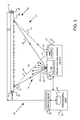
FIG. 6 is a schematic block diagram of a yet further alternative system for generating a reference image, according to an embodiment of the present invention;
FIG. 7 is a flowchart describing steps for acquiring the reference image in the system of FIG. 6, according to an embodiment of the present invention
FIG. 8 is a schematic block diagram of another alternative system for generating a reference image, according to an embodiment of the present invention;
FIG. 9 is a schematic block diagram of yet another alternative system for generating a reference image, according to an embodiment of the present invention; and
FIG. 10 is a flowchart describing steps for acquiring the reference image of the system of FIG. 8 or of FIG. 9, according to an embodiment of the present invention.
DETAILED DESCRIPTION OF EMBODIMENTS Overview
Embodiments of the present invention produce an enhanced quality reference image for a device that generates a three-dimensional (3D) map of a test object. The device projects a pattern onto a calibration object, and captures an image of the projected pattern as the reference image. The pattern is then projected onto the test object and the device images the projected pattern. The device measures transverse shifts in the imaged pattern of the test object, compared to the reference image, to generate a 3D map of the test object.
In some embodiments, the pattern is formed using coherent radiation. Speckles in the reference image, caused by non-specularity or roughness in the calibration object, are removed by applying a small relative motion between the device and the calibration object. Removal of the speckles enhances the quality of the reference image.
In some embodiments the reference image is formed by capturing two different images of the pattern projected onto the calibration object. The different images are registered with each other, and the enhanced quality reference image is generated from the registered images.
While for the sake of concreteness, the embodiments concentrate on 3D mapping device, it should be understood that the methods of the present invention are beneficially applicable to any setup requiring enhancement of the image of the projected pattern.
DETAILED DESCRIPTION
Reference is now made to FIG. 1, which is a schematic block diagram of a system 20 for generating a reference image, according to an embodiment of the present invention. FIG. 1 and the other block diagrams in this disclosure are top views. System 20 comprises a projection and imaging device 22, which is used for performing three-dimensional (3D) mapping of objects. The operation and functioning of a device similar to device 22 are described in more detail in PCT Publication WO 2007/043036, referred to in the Background of the Invention.
Device 22 comprises a projector 26, which uses a coherent source of radiation 28, typically a laser diode, followed by a projection optics 29, to generate a pattern 30 of the radiation. Pattern 30 projects in a field of view (FOV) 35 of the projector, the field of view being illustrated schematically in FIG. 1 by projector FOV bounding lines 37 and 39. The projector projects pattern 30 onto a reference object 24 acting as a calibration object for system 20, and the pattern typically images as a base reference 31 on a reference surface 33 of object 24. Projection optics 29 may vary according to application, and may include but are not limited to a diffractive optical element projector, a micro-lens projector, a diffuser-based primary speckle projector, or other type of projector utilizing coherent light. Depending on the specific projector embodiment and the system requirements for device 22, the base reference may have a relatively complicated structure. For clarity and simplicity and by way of example, in the following description the base reference is assumed to comprise an array of distinct spots distributed in some fashion over the reference surface, so that base reference 31 may also be referred to as array of spots 31. Those having ordinary skill in the art will be able to adapt the description, mutatis mutandis, for base references having a structure other than that of distinct spots.
Device 22 also comprises an image sensor 32, herein also referred to as a device camera 32. The device camera has a field of view 41, which is illustrated schematically by device camera FOV bounding lines 43 and 45. Camera 32 is configured to capture an image of the spots formed by pattern 30 on an array 34, typically a CCD (charge coupled device) array or CMOS (complementary metal-oxide-semiconductor), in the device camera. Array 34, together with optics of the camera, effectively defines a frame of reference of camera 32. The fields of view of projector 26 and device camera 32 are generally different, but by way of example are assumed to overlap at reference object 24, so that the image captured by the camera comprises all the spots projected onto the reference object by the projector.
The captured image is analyzed in a processing unit 36 of the system, to generate a reference image for use by device 22 in 3D mapping of objects other than the reference object. Such objects are assumed, by way of example, to comprise an “object-to-be-mapped” by system 20, also referred to herein as a test object.
Processing unit 36 comprises a processor 38 and a memory 40, typically including non-volatile and volatile sections. Processor 38 typically stores system operating software, including the reference image, in a non-volatile section of memory 40. Processing unit 36 may be physically separate from device 22, or alternatively, the processing unit may be incorporated together with device 22 into a single package.
The software used by processor 38 may be downloaded to processing unit 36 in electronic form, over a network, for example, or it may alternatively be supplied to the processing unit on tangible media, such as on a CD-ROM.
Once the reference image has been obtained and stored, device 22, together with processing unit 36, is able to perform 3D mapping of the test object. The 3D mapping is performed by projecting pattern 30 onto the test object, whereupon camera 32 captures an image of the pattern projected onto the test object. Processor 38 measures local transverse shifts of the spots of the pattern in the test image relative to respective spots, corresponding to spots 31, in the reference image. Using the transverse shifts, the processor is able to measure depths of the test object at the positions of the spots projected onto the test object.
As stated above, pattern 30 is formed by optics 29 using coherent light source. Because of the necessarily non-specular nature of surface 33, so called secondary speckles are generated at the surface. The term “secondary” refers to the fact that these speckles come from the roughness of the surface on which the projected pattern impinges. The secondary speckles are caused by adjacent regions of the surface scattering their incident coherent radiation so that the scattered radiation interferes constructively or destructively. The adjacent regions are typically in portions of the surface upon which a spot 31 is formed. In addition to being a function of the characteristics of surface 33, the secondary speckle characteristics depend on properties of the incident coherent radiation, as well as on the numerical aperture of the image sensor, camera 32.
Array 34 has a finite integration time, typically of the order of 33 ms, so that absent the embodiments described herein, images of the secondary speckle are integrated multiplicatively into the images of spots 31 comprising the reference image. This integration reduces, in some cases drastically, the contrast of the spot images. Other negative effects of the secondary speckles include the fact that in systems of interest the speckle image has a size of the order of a single pixel, and it is difficult or impossible to remove the speckle effects digitally.
These considerations apply to any system that uses coherent radiation to project patterns, and any situation where such patterns need to be captured. Moreover, the system/situation need not be confined to capturing an image for 3D mapping purposes only. Consequently, for substantially any object that is stationary relative to the integration time of the image sensor, and which is illuminated by coherent radiation, the image captured benefits from the methods described herein for removing speckles.
As explained below, embodiments of the present invention eliminate the deleterious effects on the reference image caused by the secondary speckles.
Device 22 is attached to a motion actuator 42, which is typically under control of processing unit 36. Actuator 42 is configured to move device 22, so that there is relative motion between reference object 24 and its surface 33, and image sensor 32. The motion is typically configured to be linear and oscillatory, and in some embodiments the linear direction of the motion is selected to be parallel to surface 33. However, there is no requirement that the motion be linear, oscillatory, and parallel to surface 33, and other types of motion, such as vibratory, or linear, oscillatory, and orthogonal to surface 33 may be applied by unit 42 to device 22. As explained below, the motion is applied to remove the effects on the reference image of the secondary speckles, and those having ordinary skill in the art will be able to determine an optimum type of motion to be applied to device 22, without undue experimentation.
FIG. 2 is a flowchart 50, describing steps for acquiring the reference image in system 20, according to an embodiment of the present invention.
In an initial step 52, projector 26 of the projection and imaging device projects pattern 30 onto reference surface 33.
In an imaging step 54, array 34 captures an image of base reference 31 generated by the projected pattern, and while capturing the image, processing unit 36 activates actuator 42 to move device 22, so that the device moves relative to reference surface 33. The type of motion applied is selected as described above with reference to FIG. 1. The amplitude of the motion is configured to be sufficient to effectively average out the effects of the secondary speckles on the image of base reference 31, while maintaining the image of the base reference very nearly constant on array 34. It will be understood that because of the characteristics of the secondary speckles, the amplitude of the motion required is small, typically finer than the resolution of camera 32, i.e., of the order of one pixel dimension or less of array 34.
In a final step 56, the acquired reference image is stored in memory 40, for use by processor 38 in 3D mapping of a test object.
FIG. 3 is a schematic block diagram of an alternative system 60 for generating a reference image, according to an embodiment of the present invention. Apart from the differences described below, the operation of system 60 is generally similar to that of system 20, and elements indicated by the same reference numerals in both systems 20 and 60 are generally similar in construction and in operation. Instead of moving device 22 (as in system 20), in system 60 the reference surface upon which spots 31 are formed is moved.
By way of example, in place of reference object 24, system 60 comprises a reference object 62, which is formed as a continuous sheet 64 in the form of a closed loop. Reference object 62 acts as a calibration object for system 60. Sheet 64 has an outer surface 66 that is non-specular. Sheet 64 is mounted on rollers 68 which may be rotated by respective rotators 70, under control of processing unit 36. In some embodiments, only one rotator is used, attached to one roller 68, and the other roller is free to rotate. Since in system 60 device 22 is not moved, actuator 42 is not present in the system.
Rotation of rollers 68 moves surface 66 parallel to itself. Typically, the rotation is unidirectional so that surface 66 moves in a loop. Alternatively, the rotation of the rollers is configured to be oscillatory, so that surface 66 also moves in an oscillatory manner.
The acquisition of the reference image in system 60 is generally similar to the acquisition in system 20, as described above with reference to FIG. 2. Thus, projector 26 initially projects pattern 30 onto reference surface 66, and array 34 captures an image of spots 31 generated by the projected pattern. While capturing the image, processing unit 36 activates rotators 70 to move surface 66, so that the surface moves relative to device 22. The amplitude of the motion is configured to be sufficient to effectively average out the effects of the secondary speckles on the image of spots 31 formed on array 34. As for system 20, in system 60 the amplitude of motion required is small, and is typically of the same order of magnitude as that of system 20.
System 60 may comprise a reference object other than reference object 62, and/or means to move the reference object other than rotators 70, since any such system only requires that the reference object move relative to device 22. Thus, alternative methods for implementing the relative motion by moving the reference object include, but are not limited to, having a reference object similar to object 24, and attaching a motion actuator similar to actuator 42 to the reference object. Other types of reference object and/or motion actuators will be familiar to those having ordinary skill in the art, and are assumed to be comprised within the scope of the present invention.
Systems 20 and 60 may be combined to form a composite embodiment of the present invention. In the composite embodiment, during acquisition by array 34 of the image of spots 31, both device 22 and the reference object are moved.
FIG. 4 is a schematic block diagram of a further alternative system 100 for generating a reference image, according to an embodiment of the present invention. Apart from the differences described below, the operation of system 100 is generally similar to that of system 20, and elements indicated by the same reference numerals in both systems 20 and 100 are generally similar in construction and in operation.
Unlike systems 20 and 60, system 100 uses two different images of a reference object, as is explained in more detail below.
System 100 comprises a projection and imaging device 102 which is generally similar to device 22, and which comprises device camera 32, described above with reference to FIG. 1. Device 102 also comprises a projector 104, which may be generally similar to projector 26, but which in system 100 may comprise as its radiation source either a coherent or an incoherent source. Hereinbelow, for simplicity, projector 104 is assumed to comprise an incoherent source 106.
In the case of an incoherent source, in place of coherent projection optics 29 (such as a diffuser or system incorporating diffractive optical elements), projector 104 comprises optics 108, which typically have a small numerical aperture, and a mask 110. Among other possible implementations, mask 110 can either be a transmission slide or a micro-lens array designed to create the pattern to be projected. The small numerical aperture of optics 108 generates a corresponding large depth of focus of an image of the mask. A pattern 112, that is generally similar to pattern 30 (but which is not necessarily formed by coherent radiation), is formed by projector 104 imaging the mask. The pattern is projected into a projector field of view 113, which is illustrated schematically by projector FOV bounding lines 115 and 117. Pattern 112 is projected onto surface 33 to form a base reference 119, herein by way of example assumed to comprise an array of spots 119 which are generally similar to spots 31, on the surface.
System 100 comprises an image sensor 114, herein also termed external camera 114, which is separate from device 102. The external camera is typically of a significantly higher quality than the device camera. Thus, the two cameras typically have at least one different optical characteristic, such as different fields of view, different resolutions, different signal to noise ratios, or different dynamic ranges. Marketing considerations typically require the cost of the device camera to be as low as possible, so that the price of devices 22 and 102 may be as low as possible. Such considerations do not apply to the cost of the external camera, which is not intended to be marketed with devices 22 or 102. Rather, as is described hereinbelow, the external camera is used for generating the reference image for device 102, typically in a production facility for the device. Consequently, external camera 114 may have one or more of its optical characteristics, referred to above, enhanced compared to that of the device camera. For simplicity, the following description assumes the optical characteristic of the two cameras to be their field of view or their resolution, so that external camera 114 may have a larger field of view than the field of view of the device camera, and/or may have a finer resolution than the resolution of the device camera. While the field of view and the resolution of the device camera is fixed according to the field of view that is decided for device 22 or device 102, also referred to herein as the product devices, it will be understood that it is often beneficial that the reference image is formed with a larger field of view and/or better fidelity than that of any particular product device.
In the following description, external camera 114 is assumed to have both a larger field of view, and a finer resolution, than the field of view and resolution of the device camera. Those of ordinary skill in the art will be able to adapt the description, mutatis mutandis, if only one of these conditions holds, i.e., for an external camera wherein either the field of view is larger or the resolution is finer than that of the device camera.
Pattern 112 projects spots 119 onto surface 33, and the projected spots are assumed to comprise a projected set 116 of the spots. Projected set 116 is also referred to herein as full set 116. A field of view 122 of camera 114, illustrated schematically by external camera FOV bounding lines 124 and 126, is configured to encompass full set 116. In contrast, field of view 41 of the device camera is configured to encompass a subset 118 of the full set, subset 118 comprising a smaller number of spots 119 than set 116.
As stated above, the resolution of external camera 114 is assumed to be finer than the resolution of device camera 32. By way of example, the finer resolution is assumed to be achieved by external camera 114 comprising a pixel array 120 having more pixels than the number of pixels in array 34. To comply with the finer resolution and larger field of view assumed for the external camera, other characteristics of the external camera and its elements may need to be different from those of the device camera. For example, the area of array 120 may need to be greater than the area of array 34. The external camera optics are assumed to be adjusted accordingly to provide the required field of view.
FIG. 5 is a flowchart 130, describing steps for acquiring the reference image in system 100, according to an embodiment of the present invention. The description assumes, by way of example, that base reference 119 comprises array of spots 119.
In an initial step 132, device 102 and external camera 114 are located in known positions, with known orientations.
In a projection and image capture step 134, projector 104 projects pattern 112 onto reference surface 33. Array 34 captures an image of subset 118 of the spots generated by the projected pattern. In addition, array 120 captures an image of the full set of the spots.
In a registration step 136, the two images are transferred to processing unit 36. The processing unit is configured to register the two images, using spots of subset 118 that are common to both images. The registration may be by any convenient method of image registration known in the art. Typically the method used comprises a feature-based algorithm, the processing unit initially identifying the spots in each image, and then correlating spots common to both images. Typically one or both of the images may need to be locally transformed by local scaling, rotating, and/or translating of regions of the images to achieve good registration. While the local transformations are typically linear, in some embodiments the transformations may be non-linear. In addition, the processing unit may apply epipolar or other geometric relations known in the art to perform the registration, using the known positions and orientations of the device camera, the external camera, and projector 104.
In a global transformation step 138, the processing unit combines the procedures described above, including the local transformations, into a global transformation of the image captured by the external camera. The global transformation encompasses the spots of the larger field of view of the external camera, and also maintains the finer resolution of the external camera. The combined procedures may be performed, for example, by using parameters derived from the local transformations to estimate coefficients of a polynomial representing the global transformation. The processing unit then applies the global transformation to the image captured by the external camera, so producing an image suitable for use by the device camera, i.e., an image that is registered with respect to the frame of reference (described above with reference to FIG. 1) of the device camera.
In a final step 140, the image produced in step 138 is stored in memory 40 for use by the device camera as its reference image. The reference image is an enhanced image, since it includes the spots of the larger field of view of the external camera, and in addition has the finer resolution of the external camera.
FIG. 6 is a schematic block diagram of a yet further alternative system 150 for generating a reference image, according to an embodiment of the present invention. Apart from the differences described below, the operation of system 150 is generally similar to that of system 100 (FIG. 4), and elements indicated by the same reference numerals in both systems 100 and 150 are generally similar in construction and in operation.
As is the case in system 100, system 150 uses two images of reference object 24. However, system 150 does not comprise external camera 114. Rather, the two images of reference object 24 are formed by device camera 32 when the object is at different distances, D1 and D2, D1>D2, from a projection and imaging device 152, which except as explained below, is generally similar to device 102. D1 and D2 are typically measured parallel to an optical axis 151 of camera 32.
Projection and imaging device 152 in system 150 comprises device camera 32 and a projector 154. Projector 154 is generally similar to projector 104, but may have a different field of view. A field of view 156 of projector 154, illustrated in FIG. 6 by projector FOV bounding lines 158 and 160, is configured so that a subset of the spots projected by the projector onto reference object 24, when the reference object is at distance D1, are within the field view of the device camera.
In one embodiment, object 24 is connected to a positioning module 162, which is controlled by processing unit 36. Module 162 is configured to reposition reference object 24 according to instructions from processing unit 36, and is also configured so that the processing unit is aware of the positions of the object. Alternatively or additionally, a positioning module generally similar to module 162 is connected to device 152, so that the device may be located in known positions by unit 36. Further alternatively, reference objects at distances D1 and D2 can be located in different physical locations, and the device 152 is statically positioned in these locations, in which case there is no need for positioning module 162.
FIG. 7 is a flowchart 180, describing steps for acquiring the reference image of system 150, according to an embodiment of the present invention. In the description, the different distances between the device and the reference object are assumed to be implemented using module 162. The description assumes, by way of example, that base reference 119 comprises array of spots 119.
In an initial step 182, module 162 locates reference object 24 in a far position PF so that it is distance D1 from device 152.
In a first projection and imaging step 184, projector 154 projects its pattern of spots 119 onto surface 33 of the reference object, and camera 32 captures a first image of the surface. The first image is also referred to herein as the far-location image.
In a second projection and imaging step 186, module 162 locates the reference object in a near position PN, so that it is distance D2, smaller than D1, from device 152. As is illustrated in FIG. 6, in the near position, a subset 164 of spots 119 is in the field of view of the device camera, and a subset 166 of the spots is not in the camera's field of view. However, spots corresponding to subset 166 are in the camera's field of view at the far position, PF. In addition, subset 164 includes a further subset 168 of spots 119, subset 168 being within the camera's field of view at the near position PN, but not in its field of view at the far position PF.
In a third projection and imaging step 188 device camera 32 captures a second image of surface 33 when the reference object is in near position PN. The second image is also referred to herein as the near-location image.
In a registration step 190, processing unit 36 registers the far-location and near-location images, using spots that are common to the two images. The registration is generally as is described for registration step 136 of flowchart 130, mutatis mutandis, using local transformations and geometric relations that are appropriate for system 150, such as relations that may be applied from the known distances D1 and D2 of the images.
In a global transformation step 192, the processing unit combines the procedures performed in the registration step into a global transformation of the spots of the far-location image onto the near-location image. Transformation step 192 is generally similar, mutatis mutandis, to transformation step 138 of flowchart 130. In transformation step 192, the processing unit produces a reference image comprising all the spots of the far-location image at near position PN. The reference image thus corresponds to an effective field of view larger than the actual FOV, as is illustrated in FIG. 6, since the reference image includes positions of subset 166 of spots 119.
Referring back to FIG. 6, the figure illustrates a beneficial property of the reference image of embodiments of the present invention: that subsets of the reference image correspond to the FOV of the device at different distances from the device. In other words, the reference image typically comprises a superset of the FOV of the device at a particular distance. This property is illustrated by the description above with reference to subset 166. which as stated, is within the far position FOV, but not within the near position FOV, and also with reference to subset 168, which is within the near position FOV, but not within the far position FOV.
Continuing with flowchart 180, in a final step 194 processing unit 36 stores the reference image produced in step 190 in memory 40.
The description above, with reference to systems 100 and 150, has assumed capturing and registering two images to produce an enhanced reference image for use in the systems. Those having ordinary skill in the art will be able to adapt the description for the cases of capturing and registering more than two images, in order to produce further enhanced reference images, and such cases are assumed to be comprised within the scope of the present invention.
FIG. 8 is a schematic block diagram of another alternative system 250 for generating a reference image, according to an embodiment of the present invention. Apart from the differences described below, the operation of system 250 is generally similar to that of system 150 (FIG. 6), and elements indicated by the same reference numerals in both systems 250 and 150 are generally similar in construction and in operation.
Unlike system 150, system 250 does not comprise positioning module 162, or reference object 24. Rather, system 250 comprises a reference object 252 which has a surface 255 having varying distances, measured parallel to optical axis 151, to device 152, so that the surface is not necessarily oriented orthogonally with respect to the optical axis. By way of example, surface 255 is assumed to be a distance D1 from device 152 at a point 251 on the reference object, and to be a distance D2 from device 152 at a point 253 on the reference object. Array of spots 119 are projected onto surface 255.
In system 250, reference object 252 and its surface are assumed to be curved, typically in the dimension substantially parallel to the triangulation base (a vector connecting camera 32 and projector 154) of device 152. Typically the curvature is preconfigured to match a geometrical disparity between camera 32 and projector 154 of device 152, so as to introduce a constant rate of shrinkage of a captured reference image at camera 32.
In FIG. 8, a line 258 corresponds to a first direction of projection from projector 154. Line 258 passes from optics 108 through a point 254 which is distant D2 from device 152 and which lies on bounding line 45. A line 260 corresponds to a second direction of projection from projector 154. Line 260 passes from optics 108 through a point 256 which is distant D1 from device 152 and which lies on bounding line 43.
Projector bounding lines 158 and 160, and lines 258 and 260, define subsets of spots 119 on surface 255. A subset 258 is bounded by lines 160 and 258; a subset 260 is bounded by lines 258 and 260; and a subset 262 is bounded by lines 260 and 158. Thus, the reference image generated on surface 255 comprises subsets of captured images of camera 32 at different distances from the camera.
FIG. 9 is a schematic block diagram of yet another alternative system 270 for generating a reference image, according to an embodiment of the present invention. Apart from the differences described below, the operation of system 270 is generally similar to that of system 250 (FIG. 8), and elements indicated by the same reference numerals in both systems 270 and 250 are generally similar in construction and in operation.
In system 270, a reference object 272 replaces reference object 252 of system 250. Reference object 272 comprises a planar surface 273 which is not orthogonal to axis 151. In system 270 the planar surface has distances from device 152 which vary from D1 to D2. As for system 250, in system 270 projector bounding lines 158 and 160, and lines 258 and 260, define subsets of spots 119 on surface 273. A subset 274 is bounded by lines 160 and 258; a subset 276 is bounded by lines 258 and 260; and a subset 278 is bounded by lines 260 and 158. Subsets 274, 276, and 278 respectively correspond to subsets 258, 260, and 262 of system 250 (FIG. 8), so that, as for system 250, the reference image generated on surface 273 comprises subsets of captured images of camera 32 at different distances from the camera.
Consideration of FIGS. 8 and 9 illustrate a property of systems 250 and 270: that using one reference object encompassing a wide field of view of the projector enables reference images to be generated for cameras having smaller fields of view than that of the projector.
FIG. 10 is a flowchart 300, describing steps for acquiring the reference image of system 250 or of system 270, according to an embodiment of the present invention. For simplicity and clarity, the description refers to system 250. Those having ordinary skill in the art will be able to adapt the description of the flowchart, mutatis mutandis, for system 270. The description assumes, by way of example, that base reference 119 comprises array of spots 119.
In an initial step 302, reference object 252 is positioned in front of device 152, and projector 154 projects spots 119 onto the surface of the reference object. Distances D1 and D2 are selected to cover a desired distance range, which typically comprises all working distances of device 152.
In an image capture step 304, camera 32 captures an image of the projected spots.
In an analysis step 306, processing unit 36 analyzes the image. The analysis straightens the image and/or allows for the depth accuracy curve of the device, as necessary, to generate a reference image. The reference image is valid over all fields of view of device 152 and all working distances of the device, and is registered with respect to a frame of reference of the camera.
In a final step 308, the reference image is stored in memory 40, for use by processor 38 in 3D mapping of a test object.
Embodiments of the present invention may be combined to produce enhanced reference images. For example, if the projector in system 100 is configured to use coherent radiation, the secondary speckles introduced into system 100 may be eliminated using system 20. Similarly, secondary speckles may also be eliminated in systems 250 and 270 using system 20. It will thus be appreciated that the embodiments described above are cited by way of example, and that the present invention is not limited to what has been particularly shown and described hereinabove. Rather, the scope of the present invention includes both combinations and subcombinations of the various features described hereinabove, as well as variations and modifications thereof which would occur to persons skilled in the art upon reading the foregoing description and which are not disclosed in the prior art.

Claims (11)

The invention claimed is:
1. A method, comprising:
providing a device that projects a pattern;
capturing a reference image of the pattern using an image sensor by projecting the pattern onto a reference surface while at least a first part of the reference surface, containing a first portion of the pattern, is located at a first distance from the image sensor and while at least a second part of the reference surface, containing a second portion of the pattern, is located at a second distance, different from the first distance, from the image sensor, and combining the first and second portions of the pattern into the reference image;
registering the captured reference image in a frame of reference of the device;
storing the registered reference image in a memory associated with the device; and
generating a three-dimensional (3D) map of an object, different from the reference surface, after storing the registered reference image by projecting the pattern onto the object, capturing a test image of the pattern on the object, and measuring local transverse shifts of the pattern in the test image relative to the reference image that is stored in the memory.
2. The method according to claim 1, wherein capturing the reference image comprises capturing a first image of the pattern projected onto the reference surface at the first distance using the image sensor, and capturing a second image of the pattern projected onto the reference surface at the second distance using the image sensor, and wherein registering the reference image comprises registering the first and second images to produce a registered reference image, and wherein storing the reference image comprises storing the registered reference image in the memory.
3. The method according to claim 1, wherein projecting the pattern comprises projecting the pattern into a first field of view, and wherein the image sensor has a second field of view different from the first field of view.
4. The method according to claim 1, wherein the reference surface is oriented with respect to the image sensor to have a first region of the reference surface at the first distance from the image sensor and to have a second region of the reference surface at the second distance, different from the first distance, from the image sensor.
5. The method according to claim 4, wherein the reference surface is planar and is oriented non-orthogonally with respect to an optical axis of the image sensor.
6. The method according to claim 4, wherein the reference surface is curved between the first distance and the second distance.
7. Apparatus, comprising:
a projection and imaging device comprising:
a projector that projects a pattern of radiation;
an image sensor that captures images of a field of view on which the pattern is projected; and
a memory, which is configured to store a reference image of the pattern,
wherein the device is configured to generate a three-dimensional (3D) map of an object, after storing the reference image in the memory, by projecting the pattern onto the object, capturing a test image of the pattern on the object, and measuring local transverse shifts of the pattern in the test image relative to the reference image that is stored in the memory; and
a system for generating the reference image, which comprises:
a reference surface, which is different from the object that is to be mapped and is configured to enable the projection and imaging device to project the pattern onto the reference surface while at least a first part of the reference surface, containing a first portion of the pattern, is located at a first distance from the image sensor and while at least a second part of the reference surface, containing a second portion of the pattern, is located at a second distance, different from the first distance, from the image sensor; and
a processor, which is configured to combine the first and second portions of the pattern into the reference image, to register the captured reference image in a frame of reference of the device, and to store the registered reference image in the memory of the device.
8. The apparatus according to claim 7, wherein the projector is configured to project the pattern into a first field of view, and wherein the field of view of the image sensor is a second field of view different from the first field of view.
9. The apparatus according to claim 7, wherein the reference surface is oriented with respect to the image sensor to have a first region of the reference surface at the first distance from the image sensor and to have a second region of the reference surface at the second distance, different from the first distance, from the image sensor.
10. The apparatus according to claim 9, wherein the reference surface is planar and is oriented non-orthogonally with respect to an optical axis of the image sensor.
11. The apparatus according to claim 9, wherein the reference surface is curved between the first distance and the second distance.
US14/301,427 2009-03-05 2014-06-11 Reference image techniques for three-dimensional sensing Active 2030-04-30 US9386299B2 (en)

Priority Applications (1)

Application Number Priority Date Filing Date Title
US14/301,427 US9386299B2 (en) 2009-03-05 2014-06-11 Reference image techniques for three-dimensional sensing

Applications Claiming Priority (3)

Application Number Priority Date Filing Date Title
US15756009P 2009-03-05 2009-03-05
US12/707,678 US8786682B2 (en) 2009-03-05 2010-02-18 Reference image techniques for three-dimensional sensing
US14/301,427 US9386299B2 (en) 2009-03-05 2014-06-11 Reference image techniques for three-dimensional sensing

Related Parent Applications (1)

Application Number Title Priority Date Filing Date
US12/707,678 Division US8786682B2 (en) 2009-03-05 2010-02-18 Reference image techniques for three-dimensional sensing

Publications (2)

Publication Number Publication Date
US20140285638A1 US20140285638A1 (en) 2014-09-25
US9386299B2 true US9386299B2 (en) 2016-07-05

Family

ID=42677901

Family Applications (2)

Application Number Title Priority Date Filing Date
US12/707,678 Active 2033-04-14 US8786682B2 (en) 2009-03-05 2010-02-18 Reference image techniques for three-dimensional sensing
US14/301,427 Active 2030-04-30 US9386299B2 (en) 2009-03-05 2014-06-11 Reference image techniques for three-dimensional sensing

Family Applications Before (1)

Application Number Title Priority Date Filing Date
US12/707,678 Active 2033-04-14 US8786682B2 (en) 2009-03-05 2010-02-18 Reference image techniques for three-dimensional sensing

Country Status (3)

Country Link
US (2) US8786682B2 (en)
CN (1) CN101825431B (en)
TW (1) TWI480832B (en)

Cited By (1)

* Cited by examiner, † Cited by third party
Publication number Priority date Publication date Assignee Title
US11852727B2 (en) 2017-12-18 2023-12-26 Apple Inc. Time-of-flight sensing using an addressable array of emitters

Families Citing this family (91)

* Cited by examiner, † Cited by third party
Publication number Priority date Publication date Assignee Title
US8400494B2 (en) 2005-10-11 2013-03-19 Primesense Ltd. Method and system for object reconstruction
US20110096182A1 (en) * 2009-10-25 2011-04-28 Prime Sense Ltd Error Compensation in Three-Dimensional Mapping
US9330324B2 (en) 2005-10-11 2016-05-03 Apple Inc. Error compensation in three-dimensional mapping
EP1994503B1 (en) 2006-03-14 2017-07-05 Apple Inc. Depth-varying light fields for three dimensional sensing
CN101496033B (en) 2006-03-14 2012-03-21 普莱姆森斯有限公司 Depth-varying light fields for three dimensional sensing
WO2008087652A2 (en) * 2007-01-21 2008-07-24 Prime Sense Ltd. Depth mapping using multi-beam illumination
US8493496B2 (en) * 2007-04-02 2013-07-23 Primesense Ltd. Depth mapping using projected patterns
WO2008155770A2 (en) * 2007-06-19 2008-12-24 Prime Sense Ltd. Distance-varying illumination and imaging techniques for depth mapping
DE112009001652T5 (en) 2008-07-08 2012-01-12 Chiaro Technologies, Inc. Multichannel recording
US8456517B2 (en) 2008-07-09 2013-06-04 Primesense Ltd. Integrated processor for 3D mapping
US9482755B2 (en) 2008-11-17 2016-11-01 Faro Technologies, Inc. Measurement system having air temperature compensation between a target and a laser tracker
US8462207B2 (en) 2009-02-12 2013-06-11 Primesense Ltd. Depth ranging with Moiré patterns
US8786682B2 (en) 2009-03-05 2014-07-22 Primesense Ltd. Reference image techniques for three-dimensional sensing
US8717417B2 (en) 2009-04-16 2014-05-06 Primesense Ltd. Three-dimensional mapping and imaging
US9582889B2 (en) 2009-07-30 2017-02-28 Apple Inc. Depth mapping based on pattern matching and stereoscopic information
US8830227B2 (en) * 2009-12-06 2014-09-09 Primesense Ltd. Depth-based gain control
US8982182B2 (en) 2010-03-01 2015-03-17 Apple Inc. Non-uniform spatial resource allocation for depth mapping
US8619265B2 (en) 2011-03-14 2013-12-31 Faro Technologies, Inc. Automatic measurement of dimensional data with a laser tracker
US9772394B2 (en) 2010-04-21 2017-09-26 Faro Technologies, Inc. Method and apparatus for following an operator and locking onto a retroreflector with a laser tracker
US9400170B2 (en) 2010-04-21 2016-07-26 Faro Technologies, Inc. Automatic measurement of dimensional data within an acceptance region by a laser tracker
US9377885B2 (en) 2010-04-21 2016-06-28 Faro Technologies, Inc. Method and apparatus for locking onto a retroreflector with a laser tracker
CN103053167B (en) 2010-08-11 2016-01-20 苹果公司 Scanning projector and the image capture module mapped for 3D
CN102466479B (en) * 2010-11-16 2013-08-21 深圳泰山在线科技有限公司 System and method for measuring anti-jamming distance of moving object
WO2012066501A1 (en) 2010-11-19 2012-05-24 Primesense Ltd. Depth mapping using time-coded illumination
US9167138B2 (en) 2010-12-06 2015-10-20 Apple Inc. Pattern projection and imaging using lens arrays
TWI459322B (en) * 2011-02-25 2014-11-01 Inst Information Industry Graphic rendering system and projecting method thereof
GB2518769A (en) 2011-03-03 2015-04-01 Faro Tech Inc Target apparatus and method
US8445878B2 (en) 2011-03-16 2013-05-21 Controlrad Systems, Inc. Radiation control and minimization system and method
US9030528B2 (en) 2011-04-04 2015-05-12 Apple Inc. Multi-zone imaging sensor and lens array
US9482529B2 (en) 2011-04-15 2016-11-01 Faro Technologies, Inc. Three-dimensional coordinate scanner and method of operation
US9686532B2 (en) 2011-04-15 2017-06-20 Faro Technologies, Inc. System and method of acquiring three-dimensional coordinates using multiple coordinate measurement devices
US9164173B2 (en) 2011-04-15 2015-10-20 Faro Technologies, Inc. Laser tracker that uses a fiber-optic coupler and an achromatic launch to align and collimate two wavelengths of light
WO2012141868A1 (en) 2011-04-15 2012-10-18 Faro Technologies, Inc. Enhanced position detector in laser tracker
KR101845226B1 (en) 2011-07-01 2018-05-18 돌비 레버러토리즈 라이쎈싱 코오포레이션 System and method for adaptive audio signal generation, coding and rendering
KR101823347B1 (en) * 2011-07-08 2018-02-01 삼성전자주식회사 Sensor and data processing system having the same
US9033516B2 (en) * 2011-09-27 2015-05-19 Qualcomm Incorporated Determining motion of projection device
CN104094081A (en) 2012-01-27 2014-10-08 法罗技术股份有限公司 Inspection method with barcode identification
US9651417B2 (en) * 2012-02-15 2017-05-16 Apple Inc. Scanning depth engine
DE102012103766A1 (en) 2012-04-27 2013-10-31 Bircher Reglomat Ag Method for controlling and / or monitoring the areas around resealable building openings
CN103424077A (en) * 2012-05-23 2013-12-04 联想(北京)有限公司 Motion detection device, detection method and electronic equipment
TWI464692B (en) * 2012-07-03 2014-12-11 Wistron Corp Method of identifying an operating object, method of constructing depth information of an operating object, and an electronic device
US10199835B2 (en) 2015-12-29 2019-02-05 Energous Corporation Radar motion detection using stepped frequency in wireless power transmission system
US10312715B2 (en) 2015-09-16 2019-06-04 Energous Corporation Systems and methods for wireless power charging
US10270261B2 (en) 2015-09-16 2019-04-23 Energous Corporation Systems and methods of object detection in wireless power charging systems
JP6082556B2 (en) * 2012-09-28 2017-02-15 日立オートモティブシステムズ株式会社 Imaging device
CN103854017B (en) * 2012-12-03 2017-03-01 联想(北京)有限公司 A kind of method of collection image information and electronic equipment
DE102012112321B4 (en) 2012-12-14 2015-03-05 Faro Technologies, Inc. Device for optically scanning and measuring an environment
TWI591584B (en) * 2012-12-26 2017-07-11 財團法人工業技術研究院 Three dimensional sensing method and three dimensional sensing apparatus
JP6089722B2 (en) * 2013-01-23 2017-03-08 富士通株式会社 Image processing apparatus, image processing method, and image processing program
DE102013002399B4 (en) * 2013-02-13 2016-12-22 Chromasens Gmbh Device for generating light patterns with a one-dimensionally focused illumination device
US9798302B2 (en) 2013-02-27 2017-10-24 Rockwell Automation Technologies, Inc. Recognition-based industrial automation control with redundant system input support
US9393695B2 (en) 2013-02-27 2016-07-19 Rockwell Automation Technologies, Inc. Recognition-based industrial automation control with person and object discrimination
US9498885B2 (en) 2013-02-27 2016-11-22 Rockwell Automation Technologies, Inc. Recognition-based industrial automation control with confidence-based decision support
US9804576B2 (en) 2013-02-27 2017-10-31 Rockwell Automation Technologies, Inc. Recognition-based industrial automation control with position and derivative decision reference
US9041914B2 (en) 2013-03-15 2015-05-26 Faro Technologies, Inc. Three-dimensional coordinate scanner and method of operation
JP6355710B2 (en) * 2013-03-15 2018-07-11 ファロ テクノロジーズ インコーポレーテッド Non-contact optical three-dimensional measuring device
US20160262685A1 (en) 2013-11-12 2016-09-15 Highland Instruments, Inc. Motion analysis systemsand methods of use thereof
US9562760B2 (en) 2014-03-10 2017-02-07 Cognex Corporation Spatially self-similar patterned illumination for depth imaging
CN104918031B (en) * 2014-03-10 2018-08-07 联想(北京)有限公司 depth recovery device and method
WO2015152829A1 (en) 2014-04-03 2015-10-08 Heptagon Micro Optics Pte. Ltd. Structured-stereo imaging assembly including separate imagers for different wavelengths
JP6337614B2 (en) * 2014-05-23 2018-06-06 セイコーエプソン株式会社 Control device, robot, and control method
FR3021784B1 (en) * 2014-05-27 2017-10-13 European Aeronautic Defence & Space Co Eads France METHOD FOR PROJECTING VIRTUAL DATA AND DEVICE FOR SAID PROJECTION
JP6408259B2 (en) * 2014-06-09 2018-10-17 株式会社キーエンス Image inspection apparatus, image inspection method, image inspection program, computer-readable recording medium, and recorded apparatus
US9395174B2 (en) 2014-06-27 2016-07-19 Faro Technologies, Inc. Determining retroreflector orientation by optimizing spatial fit
CN105306922B (en) * 2014-07-14 2017-09-29 联想(北京)有限公司 Acquisition methods and device of a kind of depth camera with reference to figure
USD733141S1 (en) 2014-09-10 2015-06-30 Faro Technologies, Inc. Laser scanner
US9503708B2 (en) * 2014-11-03 2016-11-22 Aquifi, Inc. Systems and methods for reducing z-thickness and zero-order effects in depth cameras
US10432842B2 (en) * 2015-04-06 2019-10-01 The Texas A&M University System Fusion of inertial and depth sensors for movement measurements and recognition
US9964402B2 (en) * 2015-04-24 2018-05-08 Faro Technologies, Inc. Two-camera triangulation scanner with detachable coupling mechanism
US9525863B2 (en) 2015-04-29 2016-12-20 Apple Inc. Time-of-flight depth mapping with flexible scan pattern
US10571668B2 (en) 2015-05-09 2020-02-25 Cognex Corporation Catadioptric projector systems, devices, and methods
US10528840B2 (en) 2015-06-24 2020-01-07 Stryker Corporation Method and system for surgical instrumentation setup and user preferences
JP6566768B2 (en) * 2015-07-30 2019-08-28 キヤノン株式会社 Information processing apparatus, information processing method, and program
US9871387B1 (en) 2015-09-16 2018-01-16 Energous Corporation Systems and methods of object detection using one or more video cameras in wireless power charging systems
US9893538B1 (en) 2015-09-16 2018-02-13 Energous Corporation Systems and methods of object detection in wireless power charging systems
CN108431626B (en) * 2015-12-20 2022-06-17 苹果公司 Light detection and ranging sensor
US9961318B2 (en) * 2016-01-20 2018-05-01 Seiko Epson Corporation Projector
JP6878816B2 (en) * 2016-01-20 2021-06-02 セイコーエプソン株式会社 projector
TWI651513B (en) 2016-11-15 2019-02-21 財團法人工業技術研究院 Three dimensional measuring system and measuring method thereof
CN106875435B (en) * 2016-12-14 2021-04-30 奥比中光科技集团股份有限公司 Method and system for obtaining depth image
US10666927B2 (en) * 2017-03-15 2020-05-26 Baker Hughes, A Ge Company, Llc Method and device for inspection of an asset
JP6879822B2 (en) * 2017-05-18 2021-06-02 株式会社 東京ウエルズ Work appearance inspection device and work appearance inspection method
US11494897B2 (en) 2017-07-07 2022-11-08 William F. WILEY Application to determine reading/working distance
CN109635619B (en) 2017-08-19 2021-08-31 康耐视公司 Encoding distance topology of structured light patterns for three-dimensional reconstruction
EP3444782B1 (en) 2017-08-19 2022-03-30 Cognex Corporation Coding distance topologies for structured light patterns for 3d reconstruction
WO2019213760A1 (en) 2018-05-10 2019-11-14 Daniel Licht System, method, and kit for using triggering objects to create concatenated audio/video
US10638104B2 (en) * 2018-09-14 2020-04-28 Christie Digital Systems Usa, Inc. Device, system and method for generating updated camera-projector correspondences from a reduced set of test patterns
US10861726B2 (en) * 2018-09-21 2020-12-08 Advanced Semiconductor Engineering, Inc. Apparatus and method for measuring warpage
US20200292297A1 (en) * 2019-03-15 2020-09-17 Faro Technologies, Inc. Three-dimensional measurement device
US20210158552A1 (en) * 2019-11-22 2021-05-27 Magic Leap, Inc. Systems and methods for enhanced depth determination using projection spots
WO2023195911A1 (en) * 2022-04-05 2023-10-12 Ams-Osram Asia Pacific Pte. Ltd. Calibration of depth map generating system

Citations (3)

* Cited by examiner, † Cited by third party
Publication number Priority date Publication date Assignee Title
US5289261A (en) * 1991-09-17 1994-02-22 Opton, Co., Ltd. Device for measuring a three-dimensional shape of an elongate member
US6700669B1 (en) * 2000-01-28 2004-03-02 Zheng J. Geng Method and system for three-dimensional imaging using light pattern having multiple sub-patterns
US20070057946A1 (en) * 2003-07-24 2007-03-15 Dan Albeck Method and system for the three-dimensional surface reconstruction of an object

Family Cites Families (164)

* Cited by examiner, † Cited by third party
Publication number Priority date Publication date Assignee Title
DE2951207A1 (en) * 1978-12-26 1980-07-10 Canon Kk METHOD FOR THE OPTICAL PRODUCTION OF A SPREADING PLATE
US4542376A (en) * 1983-11-03 1985-09-17 Burroughs Corporation System for electronically displaying portions of several different images on a CRT screen through respective prioritized viewports
JPS61241612A (en) * 1985-04-19 1986-10-27 Kinkashiya:Kk Three-dimensional form measuring system
US4843568A (en) * 1986-04-11 1989-06-27 Krueger Myron W Real time perception of and response to the actions of an unencumbered participant/user
JPH0615968B2 (en) * 1986-08-11 1994-03-02 伍良 松本 Three-dimensional shape measuring device
US5075562A (en) * 1990-09-20 1991-12-24 Eastman Kodak Company Method and apparatus for absolute Moire distance measurements using a grating printed on or attached to a surface
GB9116151D0 (en) 1991-07-26 1991-09-11 Isis Innovation Three-dimensional vision system
US5483261A (en) * 1992-02-14 1996-01-09 Itu Research, Inc. Graphical input controller and method with rear screen image detection
EP0559978B1 (en) * 1992-03-12 1998-08-05 International Business Machines Corporation Image processing method
US5636025A (en) * 1992-04-23 1997-06-03 Medar, Inc. System for optically measuring the surface contour of a part using more fringe techniques
US5856871A (en) * 1993-08-18 1999-01-05 Applied Spectral Imaging Ltd. Film thickness mapping using interferometric spectral imaging
US6041140A (en) * 1994-10-04 2000-03-21 Synthonics, Incorporated Apparatus for interactive image correlation for three dimensional image production
JPH08186845A (en) 1994-12-27 1996-07-16 Nobuaki Yanagisawa Focal distance controlling stereoscopic-vision television receiver
US5630043A (en) * 1995-05-11 1997-05-13 Cirrus Logic, Inc. Animated texture map apparatus and method for 3-D image displays
IL114278A (en) * 1995-06-22 2010-06-16 Microsoft Internat Holdings B Camera and method
CA2227183A1 (en) * 1995-07-18 1997-02-06 Kevin G. Harding Moire interferometry system and method with extended imaging depth
JPH09261535A (en) * 1996-03-25 1997-10-03 Sharp Corp Image pickup device
DE19638727A1 (en) 1996-09-12 1998-03-19 Ruedger Dipl Ing Rubbert Method for increasing the significance of the three-dimensional measurement of objects
JP3402138B2 (en) * 1996-09-27 2003-04-28 株式会社日立製作所 Liquid crystal display
IL119341A (en) * 1996-10-02 1999-09-22 Univ Ramot Phase-only filter for generating an arbitrary illumination pattern
IL119831A (en) 1996-12-15 2002-12-01 Cognitens Ltd Apparatus and method for 3d surface geometry reconstruction
CA2275411A1 (en) 1996-12-20 1998-07-02 Lifef/X Networks, Inc. Apparatus and method for rapid 3d image parametrization
US5838428A (en) * 1997-02-28 1998-11-17 United States Of America As Represented By The Secretary Of The Navy System and method for high resolution range imaging with split light source and pattern mask
JPH10327433A (en) 1997-05-23 1998-12-08 Minolta Co Ltd Display device for composted image
US6008813A (en) * 1997-08-01 1999-12-28 Mitsubishi Electric Information Technology Center America, Inc. (Ita) Real-time PC based volume rendering system
DE19736169A1 (en) 1997-08-20 1999-04-15 Fhu Hochschule Fuer Technik Method to measure deformation or vibration using electronic speckle pattern interferometry
US6101269A (en) * 1997-12-19 2000-08-08 Lifef/X Networks, Inc. Apparatus and method for rapid 3D image parametrization
DE19815201A1 (en) * 1998-04-04 1999-10-07 Link Johann & Ernst Gmbh & Co Measuring arrangement for detecting dimensions of test specimens, preferably of hollow bodies, in particular of bores in workpieces, and methods for measuring such dimensions
US6731391B1 (en) * 1998-05-13 2004-05-04 The Research Foundation Of State University Of New York Shadow moire surface measurement using Talbot effect
DE19821611A1 (en) * 1998-05-14 1999-11-18 Syrinx Med Tech Gmbh Recording method for spatial structure of three-dimensional surface, e.g. for person recognition
GB2352901A (en) 1999-05-12 2001-02-07 Tricorder Technology Plc Rendering three dimensional representations utilising projected light patterns
US6377700B1 (en) * 1998-06-30 2002-04-23 Intel Corporation Method and apparatus for capturing stereoscopic images using image sensors
JP3678022B2 (en) 1998-10-23 2005-08-03 コニカミノルタセンシング株式会社 3D input device
US6084712A (en) * 1998-11-03 2000-07-04 Dynamic Measurement And Inspection,Llc Three dimensional imaging using a refractive optic design
US8965898B2 (en) 1998-11-20 2015-02-24 Intheplay, Inc. Optimizations for live event, real-time, 3D object tracking
US6759646B1 (en) * 1998-11-24 2004-07-06 Intel Corporation Color interpolation for a four color mosaic pattern
JP2001166810A (en) * 1999-02-19 2001-06-22 Sanyo Electric Co Ltd Device and method for providing solid model
US6259561B1 (en) * 1999-03-26 2001-07-10 The University Of Rochester Optical system for diffusing light
US6751344B1 (en) * 1999-05-28 2004-06-15 Champion Orthotic Investments, Inc. Enhanced projector system for machine vision
US6512385B1 (en) * 1999-07-26 2003-01-28 Paul Pfaff Method for testing a device under test including the interference of two beams
US6268923B1 (en) * 1999-10-07 2001-07-31 Integral Vision, Inc. Optical method and system for measuring three-dimensional surface topography of an object having a surface contour
JP2001141430A (en) 1999-11-16 2001-05-25 Fuji Photo Film Co Ltd Image pickup device and image processing device
LT4842B (en) * 1999-12-10 2001-09-25 Uab "Geola" Universal digital holographic printer and method
US6301059B1 (en) * 2000-01-07 2001-10-09 Lucent Technologies Inc. Astigmatic compensation for an anamorphic optical system
US6937348B2 (en) * 2000-01-28 2005-08-30 Genex Technologies, Inc. Method and apparatus for generating structural pattern illumination
JP4560869B2 (en) * 2000-02-07 2010-10-13 ソニー株式会社 Glasses-free display system and backlight system
JP4265076B2 (en) * 2000-03-31 2009-05-20 沖電気工業株式会社 Multi-angle camera and automatic photographing device
KR100355718B1 (en) * 2000-06-10 2002-10-11 주식회사 메디슨 System and method for 3-d ultrasound imaging using an steerable probe
US6810135B1 (en) * 2000-06-29 2004-10-26 Trw Inc. Optimized human presence detection through elimination of background interference
TW527518B (en) 2000-07-14 2003-04-11 Massachusetts Inst Technology Method and system for high resolution, ultra fast, 3-D imaging
US7227526B2 (en) * 2000-07-24 2007-06-05 Gesturetek, Inc. Video-based image control system
US6686921B1 (en) * 2000-08-01 2004-02-03 International Business Machines Corporation Method and apparatus for acquiring a set of consistent image maps to represent the color of the surface of an object
US6754370B1 (en) * 2000-08-14 2004-06-22 The Board Of Trustees Of The Leland Stanford Junior University Real-time structured light range scanning of moving scenes
US6639684B1 (en) 2000-09-13 2003-10-28 Nextengine, Inc. Digitizer using intensity gradient to image features of three-dimensional objects
US6813440B1 (en) * 2000-10-10 2004-11-02 The Hong Kong Polytechnic University Body scanner
JP3689720B2 (en) 2000-10-16 2005-08-31 住友大阪セメント株式会社 3D shape measuring device
JP2002152776A (en) 2000-11-09 2002-05-24 Nippon Telegr & Teleph Corp <Ntt> Method and device for encoding and decoding distance image
JP2002191058A (en) * 2000-12-20 2002-07-05 Olympus Optical Co Ltd Three-dimensional image acquisition device and three- dimensional image acquisition method
JP2002213931A (en) 2001-01-17 2002-07-31 Fuji Xerox Co Ltd Instrument and method for measuring three-dimensional shape
US6841780B2 (en) * 2001-01-19 2005-01-11 Honeywell International Inc. Method and apparatus for detecting objects
JP2002365023A (en) 2001-06-08 2002-12-18 Koji Okamoto Apparatus and method for measurement of liquid level
AU2002354681A1 (en) * 2001-07-13 2003-01-29 Mems Optical, Inc. Autosteroscopic display with rotated microlens-array and method of displaying multidimensional images, especially color images
US6741251B2 (en) * 2001-08-16 2004-05-25 Hewlett-Packard Development Company, L.P. Method and apparatus for varying focus in a scene
WO2003071410A2 (en) * 2002-02-15 2003-08-28 Canesta, Inc. Gesture recognition system using depth perceptive sensors
US7369685B2 (en) * 2002-04-05 2008-05-06 Identix Corporation Vision-based operating method and system
US7811825B2 (en) 2002-04-19 2010-10-12 University Of Washington System and method for processing specimens and images for optical tomography
WO2003105289A2 (en) * 2002-06-07 2003-12-18 University Of North Carolina At Chapel Hill Methods and systems for laser based real-time structured light depth extraction
US7006709B2 (en) * 2002-06-15 2006-02-28 Microsoft Corporation System and method deghosting mosaics using multiperspective plane sweep
US20040001145A1 (en) * 2002-06-27 2004-01-01 Abbate Jeffrey A. Method and apparatus for multifield image generation and processing
US6859326B2 (en) * 2002-09-20 2005-02-22 Corning Incorporated Random microlens array for optical beam shaping and homogenization
KR100624405B1 (en) * 2002-10-01 2006-09-18 삼성전자주식회사 Substrate for mounting optical component and method for producing the same
US7194105B2 (en) * 2002-10-16 2007-03-20 Hersch Roger D Authentication of documents and articles by moiré patterns
TWI291040B (en) * 2002-11-21 2007-12-11 Solvision Inc Fast 3D height measurement method and system
US7103212B2 (en) * 2002-11-22 2006-09-05 Strider Labs, Inc. Acquisition of three-dimensional images by an active stereo technique using locally unique patterns
US20040174770A1 (en) * 2002-11-27 2004-09-09 Rees Frank L. Gauss-Rees parametric ultrawideband system
US7639419B2 (en) * 2003-02-21 2009-12-29 Kla-Tencor Technologies, Inc. Inspection system using small catadioptric objective
US7127101B2 (en) * 2003-03-10 2006-10-24 Cranul Technologies, Inc. Automatic selection of cranial remodeling device trim lines
US20040213463A1 (en) * 2003-04-22 2004-10-28 Morrison Rick Lee Multiplexed, spatially encoded illumination system for determining imaging and range estimation
US7539340B2 (en) * 2003-04-25 2009-05-26 Topcon Corporation Apparatus and method for three-dimensional coordinate measurement
CA2435935A1 (en) * 2003-07-24 2005-01-24 Guylain Lemelin Optical 3d digitizer with enlarged non-ambiguity zone
US20050111705A1 (en) * 2003-08-26 2005-05-26 Roman Waupotitsch Passive stereo sensing for 3D facial shape biometrics
US6934018B2 (en) * 2003-09-10 2005-08-23 Shearographics, Llc Tire inspection apparatus and method
US7187437B2 (en) * 2003-09-10 2007-03-06 Shearographics, Llc Plurality of light sources for inspection apparatus and method
US7874917B2 (en) * 2003-09-15 2011-01-25 Sony Computer Entertainment Inc. Methods and systems for enabling depth and direction detection when interfacing with a computer program
JP4307206B2 (en) * 2003-09-30 2009-08-05 パナソニック株式会社 Display device
US7112774B2 (en) * 2003-10-09 2006-09-26 Avago Technologies Sensor Ip (Singapore) Pte. Ltd CMOS stereo imaging system and method
US7250949B2 (en) * 2003-12-23 2007-07-31 General Electric Company Method and system for visualizing three-dimensional data
US20050135555A1 (en) * 2003-12-23 2005-06-23 Claus Bernhard Erich H. Method and system for simultaneously viewing rendered volumes
US8134637B2 (en) * 2004-01-28 2012-03-13 Microsoft Corporation Method and system to increase X-Y resolution in a depth (Z) camera using red, blue, green (RGB) sensing
US7961909B2 (en) 2006-03-08 2011-06-14 Electronic Scripting Products, Inc. Computer interface employing a manipulated object with absolute pose detection component and a display
WO2005076198A1 (en) * 2004-02-09 2005-08-18 Cheol-Gwon Kang Device for measuring 3d shape using irregular pattern and method for the same
US7427981B2 (en) * 2004-04-15 2008-09-23 Avago Technologies General Ip (Singapore) Pte. Ltd. Optical device that measures distance between the device and a surface
US7308112B2 (en) * 2004-05-14 2007-12-11 Honda Motor Co., Ltd. Sign based human-machine interaction
EP1787157B1 (en) * 2004-07-23 2014-09-24 GE Healthcare Niagara Inc. Apparatus for fluorescent confocal microscopy
US20060017656A1 (en) * 2004-07-26 2006-01-26 Visteon Global Technologies, Inc. Image intensity control in overland night vision systems
KR101183000B1 (en) * 2004-07-30 2012-09-18 익스트림 리얼리티 엘티디. A system and method for 3D space-dimension based image processing
US7120228B2 (en) 2004-09-21 2006-10-10 Jordan Valley Applied Radiation Ltd. Combined X-ray reflectometer and diffractometer
JP2006128818A (en) 2004-10-26 2006-05-18 Victor Co Of Japan Ltd Recording program and reproducing program corresponding to stereoscopic video and 3d audio, recording apparatus, reproducing apparatus and recording medium
IL165212A (en) 2004-11-15 2012-05-31 Elbit Systems Electro Optics Elop Ltd Device for scanning light
US7076024B2 (en) * 2004-12-01 2006-07-11 Jordan Valley Applied Radiation, Ltd. X-ray apparatus with dual monochromators
US20060156756A1 (en) * 2005-01-20 2006-07-20 Becke Paul E Phase change and insulating properties container and method of use
US20060221218A1 (en) * 2005-04-05 2006-10-05 Doron Adler Image sensor with improved color filter
EP2657761A3 (en) 2005-04-06 2013-12-25 Dimensional Photonics International, Inc. Multiple channel interferometric surface contour measurement system
US7560679B1 (en) 2005-05-10 2009-07-14 Siimpel, Inc. 3D camera
US7609875B2 (en) * 2005-05-27 2009-10-27 Orametrix, Inc. Scanner system and method for mapping surface of three-dimensional object
US7760173B2 (en) * 2005-07-11 2010-07-20 Casio Computer Co., Ltd. Projection display apparatus having image modulation timing changing function
US20110096182A1 (en) 2009-10-25 2011-04-28 Prime Sense Ltd Error Compensation in Three-Dimensional Mapping
US8400494B2 (en) 2005-10-11 2013-03-19 Primesense Ltd. Method and system for object reconstruction
US8050461B2 (en) * 2005-10-11 2011-11-01 Primesense Ltd. Depth-varying light fields for three dimensional sensing
US8018579B1 (en) 2005-10-21 2011-09-13 Apple Inc. Three-dimensional imaging and display system
EP1949339A2 (en) * 2005-11-04 2008-07-30 Clean Earth Technologies, Llc Tracking using an elastic cluster of trackers
US8157381B2 (en) * 2005-12-21 2012-04-17 International Business Machines Corporation Method to synchronize stereographic hardware to sequential color rendering apparatus
US7856125B2 (en) 2006-01-31 2010-12-21 University Of Southern California 3D face reconstruction from 2D images
JP4917615B2 (en) 2006-02-27 2012-04-18 プライム センス リミティド Range mapping using uncorrelated speckle
CN101496033B (en) 2006-03-14 2012-03-21 普莱姆森斯有限公司 Depth-varying light fields for three dimensional sensing
EP1994503B1 (en) 2006-03-14 2017-07-05 Apple Inc. Depth-varying light fields for three dimensional sensing
US7869649B2 (en) * 2006-05-08 2011-01-11 Panasonic Corporation Image processing device, image processing method, program, storage medium and integrated circuit
US8488895B2 (en) 2006-05-31 2013-07-16 Indiana University Research And Technology Corp. Laser scanning digital camera with pupil periphery illumination and potential for multiply scattered light imaging
US8139142B2 (en) 2006-06-01 2012-03-20 Microsoft Corporation Video manipulation of red, green, blue, distance (RGB-Z) data including segmentation, up-sampling, and background substitution techniques
WO2008014826A1 (en) 2006-08-03 2008-02-07 Alterface S.A. Method and device for identifying and extracting images of multiple users, and for recognizing user gestures
US7737394B2 (en) 2006-08-31 2010-06-15 Micron Technology, Inc. Ambient infrared detection in solid state sensors
JP5249221B2 (en) 2006-09-04 2013-07-31 コーニンクレッカ フィリップス エレクトロニクス エヌ ヴィ Method for determining depth map from image, apparatus for determining depth map
US7256899B1 (en) * 2006-10-04 2007-08-14 Ivan Faul Wireless methods and systems for three-dimensional non-contact shape sensing
US8542421B2 (en) 2006-11-17 2013-09-24 Celloptic, Inc. System, apparatus and method for extracting three-dimensional information of an object from received electromagnetic radiation
US8090194B2 (en) * 2006-11-21 2012-01-03 Mantis Vision Ltd. 3D geometric modeling and motion capture using both single and dual imaging
US7990545B2 (en) 2006-12-27 2011-08-02 Cambridge Research & Instrumentation, Inc. Surface measurement of in-vivo subjects using spot projector
US7840031B2 (en) 2007-01-12 2010-11-23 International Business Machines Corporation Tracking a range of body movement based on 3D captured image streams of a user
WO2008087652A2 (en) 2007-01-21 2008-07-24 Prime Sense Ltd. Depth mapping using multi-beam illumination
US20080212835A1 (en) 2007-03-01 2008-09-04 Amon Tavor Object Tracking by 3-Dimensional Modeling
US8150142B2 (en) 2007-04-02 2012-04-03 Prime Sense Ltd. Depth mapping using projected patterns
US8493496B2 (en) 2007-04-02 2013-07-23 Primesense Ltd. Depth mapping using projected patterns
US8488868B2 (en) 2007-04-03 2013-07-16 Her Majesty The Queen In Right Of Canada, As Represented By The Minister Of Industry, Through The Communications Research Centre Canada Generation of a depth map from a monoscopic color image for rendering stereoscopic still and video images
AU2008244494B2 (en) 2007-04-23 2010-10-21 California Institute Of Technology Single-lens 3-D imaging device using a polarization-coded aperture mask combined with a polarization-sensitive sensor
US7835561B2 (en) 2007-05-18 2010-11-16 Visiongate, Inc. Method for image processing and reconstruction of images for optical tomography
WO2008155770A2 (en) 2007-06-19 2008-12-24 Prime Sense Ltd. Distance-varying illumination and imaging techniques for depth mapping
CA2693666A1 (en) 2007-07-12 2009-01-15 Izzat H. Izzat System and method for three-dimensional object reconstruction from two-dimensional images
JP4412362B2 (en) 2007-07-18 2010-02-10 船井電機株式会社 Compound eye imaging device
US20090060307A1 (en) 2007-08-27 2009-03-05 Siemens Medical Solutions Usa, Inc. Tensor Voting System and Method
DE102007045332B4 (en) 2007-09-17 2019-01-17 Seereal Technologies S.A. Holographic display for reconstructing a scene
KR100858034B1 (en) 2007-10-18 2008-09-10 (주)실리콘화일 One chip image sensor for measuring vitality of subject
US8166421B2 (en) 2008-01-14 2012-04-24 Primesense Ltd. Three-dimensional user interface
US8176497B2 (en) 2008-01-16 2012-05-08 Dell Products, Lp Method to dynamically provision additional computer resources to handle peak database workloads
WO2009093228A2 (en) 2008-01-21 2009-07-30 Prime Sense Ltd. Optical designs for zero order reduction
US8384997B2 (en) 2008-01-21 2013-02-26 Primesense Ltd Optical pattern projection
DE102008011350A1 (en) 2008-02-27 2009-09-03 Loeffler Technology Gmbh Apparatus and method for real-time detection of electromagnetic THz radiation
US8121351B2 (en) 2008-03-09 2012-02-21 Microsoft International Holdings B.V. Identification of objects in a 3D video using non/over reflective clothing
US8035806B2 (en) 2008-05-13 2011-10-11 Samsung Electronics Co., Ltd. Distance measuring sensor including double transfer gate and three dimensional color image sensor including the distance measuring sensor
CN201259570Y (en) * 2008-05-27 2009-06-17 北京中视中科光电技术有限公司 A decoherence device
US8456517B2 (en) 2008-07-09 2013-06-04 Primesense Ltd. Integrated processor for 3D mapping
CN100573033C (en) * 2008-07-15 2009-12-23 合肥工业大学 Three-dimensional surface model building system based on binocular
TWM352201U (en) * 2008-10-15 2009-03-01 Nat Applied Res Laboratories Projection auxiliary device for rapid adjustment of 3-D stereoscopic image
US8462207B2 (en) 2009-02-12 2013-06-11 Primesense Ltd. Depth ranging with Moiré patterns
US8786682B2 (en) 2009-03-05 2014-07-22 Primesense Ltd. Reference image techniques for three-dimensional sensing
US8717417B2 (en) 2009-04-16 2014-05-06 Primesense Ltd. Three-dimensional mapping and imaging
US8503720B2 (en) 2009-05-01 2013-08-06 Microsoft Corporation Human body pose estimation
US8744121B2 (en) 2009-05-29 2014-06-03 Microsoft Corporation Device for identifying and tracking multiple humans over time
EP2275990B1 (en) 2009-07-06 2012-09-26 Sick Ag 3D sensor
US9582889B2 (en) 2009-07-30 2017-02-28 Apple Inc. Depth mapping based on pattern matching and stereoscopic information
US8773514B2 (en) 2009-08-27 2014-07-08 California Institute Of Technology Accurate 3D object reconstruction using a handheld device with a projected light pattern
US8830227B2 (en) 2009-12-06 2014-09-09 Primesense Ltd. Depth-based gain control
US8320621B2 (en) 2009-12-21 2012-11-27 Microsoft Corporation Depth projector system with integrated VCSEL array
US8982182B2 (en) 2010-03-01 2015-03-17 Apple Inc. Non-uniform spatial resource allocation for depth mapping
US8330804B2 (en) 2010-05-12 2012-12-11 Microsoft Corporation Scanned-beam depth mapping to 2D image
US8654152B2 (en) 2010-06-21 2014-02-18 Microsoft Corporation Compartmentalizing focus area within field of view

Patent Citations (3)

* Cited by examiner, † Cited by third party
Publication number Priority date Publication date Assignee Title
US5289261A (en) * 1991-09-17 1994-02-22 Opton, Co., Ltd. Device for measuring a three-dimensional shape of an elongate member
US6700669B1 (en) * 2000-01-28 2004-03-02 Zheng J. Geng Method and system for three-dimensional imaging using light pattern having multiple sub-patterns
US20070057946A1 (en) * 2003-07-24 2007-03-15 Dan Albeck Method and system for the three-dimensional surface reconstruction of an object

Cited By (1)

* Cited by examiner, † Cited by third party
Publication number Priority date Publication date Assignee Title
US11852727B2 (en) 2017-12-18 2023-12-26 Apple Inc. Time-of-flight sensing using an addressable array of emitters

Also Published As

Publication number Publication date
US20140285638A1 (en) 2014-09-25
TWI480832B (en) 2015-04-11
CN101825431B (en) 2014-12-24
TW201033938A (en) 2010-09-16
US8786682B2 (en) 2014-07-22
US20100225746A1 (en) 2010-09-09
CN101825431A (en) 2010-09-08

Similar Documents

Publication Publication Date Title
US9386299B2 (en) Reference image techniques for three-dimensional sensing
Feng et al. Fast three-dimensional measurements for dynamic scenes with shiny surfaces
EP2751521B1 (en) Method and system for alignment of a pattern on a spatial coded slide image
EP2141448B1 (en) Calibration of a profile measuring system
US9330324B2 (en) Error compensation in three-dimensional mapping
US10218955B2 (en) Motion blur compensation
US6741279B1 (en) System and method for capturing document orientation information with a digital camera
US9275431B2 (en) Method and system for calibrating laser measuring apparatus
TW488145B (en) Three-dimensional profile scanning system
US20110096182A1 (en) Error Compensation in Three-Dimensional Mapping
US20140152771A1 (en) Method and apparatus of profile measurement
JP2002213931A (en) Instrument and method for measuring three-dimensional shape
US20230199324A1 (en) Projection unit and photographing apparatus comprising same projection unit, processor, and imaging device
JP4843544B2 (en) 3D image correction method and apparatus
CN112469361A (en) Apparatus, method and system for generating dynamic projection patterns in confocal cameras
US20210150744A1 (en) System and method for hybrid depth estimation
Zhang et al. A novel 3D multispectral vision system based on filter wheel cameras
Lindner et al. New insights into the calibration of ToF-sensors
Wang et al. Dual structured light 3d using a 1d sensor
JP2010256296A (en) Omnidirectional three-dimensional space recognition input apparatus
Chen et al. Finding optimal focusing distance and edge blur distribution for weakly calibrated 3-D vision
US20190178628A1 (en) System and method for depth estimation using a movable image sensor and illumination source
Gribben et al. Calibration for 3D imaging with a single-pixel camera
CA2810587C (en) Method and system for alignment of a pattern on a spatial coded slide image
Kumar et al. Non-frontal camera calibration using focal stack imagery

Legal Events

Date Code Title Description
AS Assignment

Owner name: PRIMESENSE LTD., ISRAEL

Free format text: ASSIGNMENT OF ASSIGNORS INTEREST;ASSIGNORS:SHPUNT, ALEXANDER;RAIS, DMITRI;GALEZER, NIV;SIGNING DATES FROM 20100216 TO 20100217;REEL/FRAME:033073/0649

AS Assignment

Owner name: APPLE INC., CALIFORNIA

Free format text: ASSIGNMENT OF ASSIGNORS INTEREST;ASSIGNOR:PRIMESENSE LTD.;REEL/FRAME:034293/0092

Effective date: 20140828

AS Assignment

Owner name: APPLE INC., CALIFORNIA

Free format text: CORRECTIVE ASSIGNMENT TO CORRECT THE APPLICATION # 13840451 AND REPLACE IT WITH CORRECT APPLICATION # 13810451 PREVIOUSLY RECORDED ON REEL 034293 FRAME 0092. ASSIGNOR(S) HEREBY CONFIRMS THE ASSIGNMENT;ASSIGNOR:PRIMESENSE LTD.;REEL/FRAME:035624/0091

Effective date: 20140828

STCF Information on status: patent grant

Free format text: PATENTED CASE

MAFP Maintenance fee payment

Free format text: PAYMENT OF MAINTENANCE FEE, 4TH YEAR, LARGE ENTITY (ORIGINAL EVENT CODE: M1551); ENTITY STATUS OF PATENT OWNER: LARGE ENTITY

Year of fee payment: 4

MAFP Maintenance fee payment

Free format text: PAYMENT OF MAINTENANCE FEE, 8TH YEAR, LARGE ENTITY (ORIGINAL EVENT CODE: M1552); ENTITY STATUS OF PATENT OWNER: LARGE ENTITY

Year of fee payment: 8