WO2003061370A1 - Method and apparatus for controlling atmospheric conditions - Google Patents

Method and apparatus for controlling atmospheric conditions Download PDF

Info

Publication number
WO2003061370A1
WO2003061370A1 PCT/IL2002/001036 IL0201036W WO03061370A1 WO 2003061370 A1 WO2003061370 A1 WO 2003061370A1 IL 0201036 W IL0201036 W IL 0201036W WO 03061370 A1 WO03061370 A1 WO 03061370A1
Authority
WO
WIPO (PCT)
Prior art keywords
seeding
droplets
charged
atmosphere
flow stream
Prior art date
Application number
PCT/IL2002/001036
Other languages
French (fr)
Other versions
WO2003061370A8 (en
Inventor
Alexander Khain
Yuri Feldman
Mark Pinsky
Vladimir Arkhipov
Yaroslav Ryabov
Alexander Puzenko
Original Assignee
Yissum Research Development Company Of The Hebrew University Of Jerusalem
Priority date (The priority date is an assumption and is not a legal conclusion. Google has not performed a legal analysis and makes no representation as to the accuracy of the date listed.)
Filing date
Publication date
Application filed by Yissum Research Development Company Of The Hebrew University Of Jerusalem filed Critical Yissum Research Development Company Of The Hebrew University Of Jerusalem
Priority to MXPA04006194A priority Critical patent/MXPA04006194A/en
Priority to AT02806549T priority patent/ATE313941T1/en
Priority to EP02806549A priority patent/EP1467611B1/en
Priority to AU2002367449A priority patent/AU2002367449B2/en
Priority to DE60208445T priority patent/DE60208445T2/en
Priority to IL16163202A priority patent/IL161632A0/en
Publication of WO2003061370A1 publication Critical patent/WO2003061370A1/en
Priority to US10/726,563 priority patent/US20040134997A1/en
Priority to IL161632A priority patent/IL161632A/en
Publication of WO2003061370A8 publication Critical patent/WO2003061370A8/en

Links

Classifications

    • EFIXED CONSTRUCTIONS
    • E01CONSTRUCTION OF ROADS, RAILWAYS, OR BRIDGES
    • E01HSTREET CLEANING; CLEANING OF PERMANENT WAYS; CLEANING BEACHES; DISPERSING OR PREVENTING FOG IN GENERAL CLEANING STREET OR RAILWAY FURNITURE OR TUNNEL WALLS
    • E01H13/00Dispersing or preventing fog in general, e.g. on roads, on airfields
    • AHUMAN NECESSITIES
    • A01AGRICULTURE; FORESTRY; ANIMAL HUSBANDRY; HUNTING; TRAPPING; FISHING
    • A01GHORTICULTURE; CULTIVATION OF VEGETABLES, FLOWERS, RICE, FRUIT, VINES, HOPS OR SEAWEED; FORESTRY; WATERING
    • A01G15/00Devices or methods for influencing weather conditions

Definitions

  • This invention relates to a method and apparatus for weather control and modification, and in particular, for controlling atmospheric conditions by seeding dispersing materials in the atmosphere causing the precipitation of water therein.
  • Fig. 1 illustrates a scheme of collisions of small droplets 11 having a radius of r with a large drop 12 (also known as a "drop-collector") having a radius of R.
  • the drop 12 moving under the force of gravity may collect the small droplets locating within a cylinder 13.
  • a volume of the cylinder 13 over a unit of time reads:
  • V ⁇ (R+rj 2 [V R - V r ], (1) wherein ⁇ (R+r) is the area of a geometric cross-section 14; and V r and V R are the velocities of the droplets 11 and the drop-collector 12, respectively.
  • a collision rate N (the number of collisions per a unit of time) may be expressed as a product of the volume of the cylinder 13 and the concentration C of the droplets 11, to wit:
  • an effective collision rate N e ff can be determined according to the following equation:
  • Fig. 2 shows a dependence of the collision efficiency E on the ratio r/R plotted for various radii R of the drop-collector (12 in Fig. 1). It can be appreciated that when the drop collectors have a small radius, i.e. around 10 microns (curve 21), the value of the collision efficiency is very small (ranging from 10 " to 10 " ). In other words, the small droplets, in fact, do not collide over a reasonable period of time.
  • the collision efficiency E has a value sufficient to produce collisions, i.e. larger than 0.1 (curves 22-24).
  • This drop-collector size is usually thought of as the minimum drop size necessary for triggering a process of collisions and creating the raindrops, i.e., drops larger than about 50 microns in radius.
  • Glaciogenic seeding may be accomplished, for example, by vaporizing silver iodide at a high temperature and causing it to recrystallize, or by spraying into the atmosphere a solution of silver iodide in ammonia, or by burning a solution of silver iodide in acetone.
  • Various methods of generating fine particles and multicomponent aerosols on the basis of glaciogenic seeding techniques for the precipitation of atmospheric water are disclosed, for example, in U.S. Pat. No. 3,429,507 to Jones; U.S. Pat. No. 3,613,992 to Knollenberg; U.S. Pat. No. 3,788,543 to Amand et al; U.S. Pat. No.
  • glaciogenic seeding methods are their limited operability, since they may be utilized only when cloud or fog water droplets are below the freezing point of water (around 0 C).
  • One such technique for triggering raindrop formation through the acceleration of large droplets formation is the hygroscopic seeding technique.
  • This technique is widely utilized for rain enhancement and fog dispersal (see, for example, G.B. Pat. No 1,110,768; U.S. Pat. No. 3,378,201 to Glew et al; U.S. Pat. No. 3,608,810 to Kooser; U.S. Pat. No. 3,608,820 to Kooser; U.S. Pat. No. 3,659,785 to Nelson; U.S. Pat. No. 3,802,624 to Kuhne; U.S. Pat. No. 3,896,993 to Serpolay; U.S. Pat. No.
  • hygroscopic materials widely used for cloud seeding is particles obtained by burning (flares).
  • these materials contain mainly small particles (less than 1 micron in radius), leading to the growth of small droplets, which are ineffective for precipitation.
  • the fraction of the large particles (effective for the purpose of creating drop-collectors) in the flares is remarkably lower than that of the small particles. Since the effects of the small and large particles on the drop growth are opposite, the total effect of the seeding is not clear (see, for example, R.T. Bruintjes, "A review of cloud seeding experiments to enhance precipitation and some new prospects ", Bull. Amer. Met. Soc, 1999, V. 80, P. 805-819).
  • U.S. Pat. No. 4,475,927 to Loos describes a technique for the abatement of fog in a space over an aircraft approach zone and runway. According to this technique, charged droplets of both polarities are introduced in the space by air jets. These positively charged droplets having sufficiently low mobility in order to stay long enough are blown aloft to form a virtual electrode suspended at an appropriate height above the ground. The negatively charged droplets (collector drops) are given high enough mobility for collecting of fog drops in an upward motion in the electric field created between the spaced-apart positively and negatively charged droplets.
  • U.S. Pat. No. 4,671,805 to Gourdine describes an EGD (electro- gas-dynamic) system deployed in an array and used for the precipitation of fog over airports.
  • the patent discloses a technique for producing a cloud of sub-micron size charged water droplets that are sprayed into the atmosphere for creating a space-charge cloud above a runway extending to a height of a few tens of meters.
  • the cloud has a maximum electric field strength at the ground, and a zero field strength at the top of the cloud.
  • the charged water droplets, in their earthward motion under the electric force attach themselves to any other particles that may be suspended in the space-charge cloud. Precipitation occurs also as wind transports the spaced-charge cloud.
  • U.S. Pat. No. 4,684,063 to Goudy, Jr. describes a mixer/charger apparatus for a variety of purposes employed simultaneously to mix and to electrically charge a fluid flowing therethrough.
  • the mixer/charger apparatus includes a liquid supply from which the charged mist ultimately is produced for seeding clouds.
  • the apparatus employs an air input supply that is delivered to a mixer/charger that produces a charged air output used to effect seeding function.
  • the present invention satisfies the aforementioned need by providing a novel method of controlling atmospheric conditions in a portion of the atmosphere for weather modification.
  • the portion of the atmosphere may, for example, be a portion of a cloud or fog containing water droplets having different sizes dispersed therein.
  • the droplet size is usually distributed in a broad spectrum of sizes.
  • the control of atmospheric conditions is carried out by controUably urging the collisions between the water droplets in the atmosphere so as to cause their controllable coalescence.
  • the urging is characterized by adjusting non-gravitational attraction forces between the droplets to a predetermined value so as to alter a collision rate between the water droplets to a desired value.
  • the changes of the non-gravitational attraction forces between the droplets are achieved by dosed seeding in a portion of a cloud or fog a seeding material that is electrically charged to a required magnitude and polarity.
  • the seeding material contains fine particles of a particulate material.
  • the seeding material contains seeding water droplets which are collected from the cloud or fog, and then electrically charged to a predetermined magnitude and polarity.
  • the seeding material contains particles of a particulate material together with seeding water droplets.
  • the ratio between a concentration of the particles and the concentration of the water droplets has a predetermined value.
  • the dosed seeding of the charged seeding materials can control the concentration of the charged droplets in the cloud or fog, the electric attraction between the charged droplets with neutral droplets as well as the electric interaction between the charged droplets.
  • the droplets in natural clouds and fogs are usually electrically neutral and represent weak salt solutions.
  • the charged seeding material utilized for seeding may be obtained, for example, by passing a particulate material and/or water droplets through an electric discharge (e.g., a corona discharge).
  • a charged seeding element When an element of the charged seeding materials (hereinafter also referred to as a charged seeding element) approaches an electrically neutral droplet at a distance sufficient for electrical interaction, a charge with a polarity opposite to the charge of the element is induced on the side of the droplet facing the element.
  • the induced charge causes an electrical attraction between the element and droplet, i.e. a non-gravitational attraction. This attraction results in a close approach and capture of the element by the droplet.
  • the droplet that received the charge from the element can, in its turn, attract another electrically neutral droplet with a consequent approach and coalescence that would not be possible in the case of a pure gravity-induced attraction.
  • the foregoing need is also accomplished by providing an apparatus for controlling atmospheric conditions in a portion of the atmosphere containing microscopic water droplets.
  • the apparatus includes a chamber for providing a element flow stream of uncharged seeding elements, a charger coupled to the chamber for charging the elements in the element flow stream, a seeder for controUably scattering the charged seeding elements in the atmosphere and a control module for controlling the operation of the apparatus.
  • the chamber of the apparatus includes a feeder for allowing the introduction of raw material into the chamber, a mixer for mixing an air flow stream with a particulate material derived from the raw material and an outlet for releasing an output obtained thereby to the charger.
  • the air flow stream can, for example, be provided by a fan coupled to the chamber.
  • the air flow stream is provided by an inlet arranged in the chamber.
  • the inlet is fitted for receiving an input air flow stream containing atmospheric water droplets and transferring this stream to the chamber thereby providing the air flow stream containing atmospheric water droplets.
  • a suction device can be arranged in the inlet for the facilitation of the receiving of the input air flow stream from the atmosphere.
  • the control module of the apparatus is equipped with conventional devices for indicating and controlling certain parameters such as the amount and kind of raw material to be used, the strain of the air in the air flow stream, the strain of the element flow stream, the strain of the charged element flow stream, the size, charge and concentration of the seeding elements in the element flow stream, etc.
  • the control module of the apparatus can include a first strain regulator arranged in the inlet for producing a first sensor signal representative of the strain of the air in the air flow stream.
  • the control module is responsive to the first sensor signal for controlling the strain.
  • the control module can also include a second strain regulator arranged in the outlet for producing a second sensor signal representative of the strain of the element flow stream.
  • the control module is responsive to the second sensor signal for controlling the strain. Further, the module can also include a third strain regulator arranged in the seeder for producing a third sensor signal representative of the strain of the charged element flow stream. The control module is responsive to the third sensor signal for controlling the strain.
  • the control module can include a charge regulator arranged in the charger and is responsive to a signal produced thereby for controlling the charge magnitude and/or polarity of the charged particles.
  • the apparatus receives electric power from an electrical power source and can also include a burner coupled to the chamber for burning the raw material so as to form the particulate material as a combustion product.
  • the control module preferably includes a temperature regulator arranged in the chamber. The temperature regulator is responsive to a signal produced thereby for controlling the temperature in the burner.
  • the technique of the present invention for controlling the atmospheric conditions has many of the advantages of the aforementioned prior art techniques, while simultaneously overcoming some of the disadvantages normally associated therewith.
  • none of the techniques addresses the controllable seeding of charged particulate materials.
  • the method of the present invention can provide a significantly higher collision efficiency than the conventional methods used for seeding particulate materials, which lack the step of charging the particles.
  • the charging of particulate seed materials can even provide collisions and precipitation of small droplets, having sizes of 1-10 microns in radius, that is impossible in the glaciogenic and hygroscopic seeding techniques.
  • not only particles having a size higher than 1 micron can serve as a seed agent, but even rather small particles of about 0.1 to 1 micron do so.
  • the competing effects of small and large particles, that crucially decrease the efficiency of the prior art methods of glaciogenic and hygroscopic seeding are eliminated, and both small and large charged particles can accelerate the process of large drop formation.
  • the raw particulate material utilized for producing charged particles can be selected from a very broad type of conventional materials. Therefore, many inexpensive and easily produced materials (e.g., soot) may be utilized.
  • a method of controlling atmospheric conditions in a portion of the atmosphere containing microscopic water droplets dispersed therein comprising the step of controUably altering an effective collision rate between the water droplets so as to produce their desired coalescence and precipitation.
  • an apparatus for controlling atmospheric conditions in a portion of the atmosphere containing microscopic water droplets dispersed therein comprising: a chamber for providing an element flow stream containing uncharged seeding elements having a predetermined size; a charger downstream of the chamber and in communication therewith for charging said uncharged seeding elements in said element flow stream so as to produce charged seeding elements having a predetermined polarity and charge magnitude; a seeder for controllable scattering said charged seeding elements in said portion of the atmosphere; a control module for controlling operation of the apparatus; and an electrical power source for providing electrical power required for operation of the apparatus.
  • Fig. 1 illustrates a scheme of collisions of small droplets with a large drop (a drop-collector);
  • Fig. 2 illustrates an example of the dependence of the collision efficiency on the ratio between the small uncharged droplet and the uncharged drop-collector of Fig. 1, shown for various radii of the drop-collector;
  • Fig. 3 illustrates an example of the dependence of an electric attraction force between a typical droplet and a typical charged particle on the distance therebetween;
  • Fig. 4 illustrates three examples of the dependence of the collision efficiency on the droplet charge for cloud
  • Fig. 5 illustrates two examples of the dependence of the collision efficiency on the droplet charge for fog
  • Fig. 6A is a schematic block diagram of an apparatus according to one embodiment of the present invention
  • Fig. 6B is a schematic block diagram of an apparatus according to another embodiment of the present invention.
  • Fig. 7 illustrates two examples of the time dependence of visibility in fog seeded by charged seeding elements.
  • Fig. 8 illustrates four examples of the time dependence of the relative rainwater content in a cloud seeded by charged elements.
  • the principles and operation of a method and an apparatus according to the present invention may be better understood with reference to the drawings and the accompanying description, it being understood that these drawings are given for illustrative purposes only and are not meant to be limiting.
  • the present invention provides a novel method and apparatus for controlling atmospheric conditions in a portion of the atmosphere for weather modification.
  • the portion of the atmosphere may, for example, be a portion of a cloud or fog containing water droplets having different sizes dispersed therein.
  • the control of atmospheric conditions is carried out by controUably urging the collisions between the water droplets in the atmosphere so as to cause their controllable coalescence.
  • the urging is characterized by adjusting non-gravitational attraction forces between the droplets to a predetermined value so as to alter a collision rate between the water droplets to a desired value.
  • the changes of the non-gravitational attraction forces between the droplets are achieved by dosed seeding in a portion of a cloud or fog of a seeding material that is electrically charged to a required magnitude and polarity.
  • the seeding material contains fine particles of a particulate material.
  • the seeding material contains seeding water droplets which are collected from the cloud or fog, and then electrically charged to a predetermined magnitude and polarity.
  • the seeding material contains particles of a particulate material together with seeding water droplets.
  • the ratio between a concentration of the particles and the concentration of the water droplets has a predetermined value.
  • the charged seeding material utilized for seeding contains charged seeding elements, such as charged fine particles and/or water droplets.
  • the charged seeding material can be obtained, for example, by passing an uncharged seeding material through an electric discharge (e.g., a corona discharge).
  • the dosed seeding of the charged materials controls the concentration of the charged droplets and the electric attraction between the charged droplets with neutral droplets as well as the electrical interaction between the charged droplets.
  • the droplets in natural clouds and fogs are usually electrically neutral and represent weak salt solutions.
  • a charge with a polarity opposite to the charge of the element is induced on the side of the droplet that is facing the particle.
  • This induced charge causes a non-gravitational attraction, such as an electrical attraction between the element and droplet.
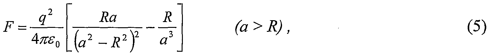
  • the magnitude of the attraction force in air can, for example, be derived from the following equation (see, for example, B.I. Bleaney and B. Bleaney, Electricity and Magnetism, Oxford University Press, Third Edition, 1976, v. 1, p. 58): 15
  • R is the radius of the neutral droplet
  • a is the distance between the centers of the charged element and the droplet
  • q is the element charge
  • FIG. 3 illustrates the dependence of the electric attraction force between a droplet and a charged element (calculated by using Eq. (5)) on the distance between the droplet and element.
  • This attraction results in a close approach and capture of the charged element by the droplet.
  • the droplet that received the charge from the charged element can, in its turn, attract another electrically neutral droplet with consequent approach and coalescence that would not be possible in the case of pure gravity-induced attraction.
  • the elements utilized for seeding may have a spread of sizes ranging from sub-micron to several microns size, e.g., between 0.1 and 20 microns.
  • the charge may have negative or positive polarity, and maximum magnitude of such charged elements may, e.g., range from about +10 "16 Coulomb to about +10 "12 Coulomb.
  • the collision efficiency can be calculated by utilizing Eq. (3).
  • Fig. 1 an example of the case of axisymmetric geometry of the collisions is illustrated.
  • the collision cross section 17 is a circle having a center 18 located on a vertical axis 19 passing through a center 10 of the large drop 12.
  • a calculation of a radius of the collision cross section 17 can be carried out by numerical simulation experiments of the approach of the small droplets 11 to the large drop 12.
  • various state-of the-art mathematical models can be used for a hydrodynamic description of the droplet motions.
  • a known per se superposition method can be considered, according to which each droplet is assumed to move under the gravitational, electric, buoyancy and drag forces in the flow induced by its counterpart moving alone. This method is described in the following publications:
  • a mutual motion of the large drop 12 relative to one small droplet that is selected from the droplets 11 can be carried out.
  • the small droplet 111 is selected subject to the condition that it is located on the axis 19 below the large drop 12 at a distance of larger than 30R (i.e., 30 radii of the large drop) from the large drop 12.
  • the distance is selected subject to the condition that at the start of the simulation, the electric and hydrodynamic interactions between the drop 12 and the droplet 111 should be insignificant.
  • the droplet 112 can also be placed at the distance of 3 OR from the large drop 12. However, the initial distance of small droplet 112 from the
  • the collisions between the small droplets and the large drop may take place only when the initial deviations of the small droplets from the vertical axis are relatively small.
  • the initial deviations start to exceed a certain value, the small droplets will move around the
  • This distance (deviation) separating a zone of collisions from the non-collision zone can be defined as a radius of the collision cross-section 17.
  • the large drop 12 can be considered to be electrically neutral and ti e small droplets 11 to be electrically charged. In this case, in order to adjust
  • the simulations can be run for various sizes of the large drop as well as various sizes and charge of the small droplets.
  • a collision efficiency between the droplets and particles when necessary, can be calculated in the same manner as the collision efficiency between the drops and droplets.
  • Fig. 4 three examples of calculations of the collision efficiency between the drop-collector and droplets (particles) as a function of the droplet (particle) charge are illustrated.
  • the size of the drop-collector is 10 microns in radius and the sizes of the small droplets (particles) are 1 micron (curve 41), 2 microns (curve 42) and 5 microns (curve 41), 1 microns (curve 42) and 5 microns (curve 41), 2 microns (curve 42) and 5 microns (curve
  • the collision efficiency has a magnitude of about 0.003, 0.01 and 0.02 for the droplets having the size of 1 micron, 2 microns and 5 microns, respectively. This means that the drop and droplets, in fact, do not collide over a reasonable period of time.
  • the situation changes when the droplets are charged.
  • the collision efficiency between the drop-collector and the 5 micron droplet increases by about 10 times, when the droplet receives a charge having a value of
  • the collision efficiency increases even more drastically for the droplets having radii of 1 micron and 2 microns.
  • the collision efficiency increases by about two orders of magnitude for the droplets having a radius of 2 microns (see curve 43) and by about three orders of magnitude for the droplets having a radius of 1 micron (see curve 43).
  • the collision efficiency for certain situations can exceed 1 (see curve 41).
  • the collision cross section (17 in Fig. 1) is larger than the geometrical cross-section (14 in Fig. 1), meaning that even the droplets located outside the volume of the cylinder (13 in Fig. 1) participate in the collisions.
  • the collision efficiency may be varied in a rather broad range, for example, from 0.001 to 100.
  • Fig. 5 illustrates examples of calculations of the collision efficiency for a situation relevant to fogs containing relatively small droplet (1-3 microns).
  • the collision efficiency is calculated as a function of the droplet (particle) charge for the drop-collectors having radius of 2 microns (see curve 51) and 3 microns (see curve 52) interacting with the small droplets (particles) having the radius of 1 micron.
  • the collision efficiency is about 10 " .
  • the collision efficiency between the neutral and charged droplets increases by 2 to 3 orders of magnitude, depending on the charge value.
  • the measure of the efficiency of the fog abatement techniques can be characterized by improvement of visibility in fog after the injection of seeding elements.
  • the visibility (VIS) is related to the extinction coefficient ⁇ by the known equation:
  • is the contrast threshold, usually equal to 0.02 (see, for example, B. A. Kunkel, "Parameterization of droplet terminal velocity and extinction coefficient in fog models ", Journal of climate and Applied Meteorology, 1984, v. 23, p. 34-41).
  • the extinction coefficient ⁇ characterizes the rate of the weakening of light beam energy in fog. It is known (see, for example, Zuev V.E. "Propagation of visible and infrared radiation in the atmosphere", Israel Program for Scientific Translations Ltd, Halsted Press, New York-Toronto- Jerusalem-London, 1974, p. 230), that the extinction coefficient ⁇ depends on the droplet size distribution in fog, and can be calculated by using the following equations:
  • N is the droplet concentration
  • a is the droplet radius
  • f( ⁇ ) is the droplet size distribution function in fog (or in a cloud)
  • n - 1.33 is the refractive index of water
  • is the wavelength of the scattered radiation.
  • the time evolution of the droplet size distribution caused by the droplet collisions must be determined. It is known in the art that the evolution of the droplet spectrum with time can be obtained by solving the stochastic collection equation (see, for example, A. Bott, "A flux method for the numerical solution of the stochastic collection equation ", J. Atmos. Set, 1998, v. 55, p. 2284-2293; and A.P. Khain, M. Ovtchinnikov, M. Pinsky, A. Pokrovsky, and H. Krugliak, “Notes on the state-of-the-art numerical modeling of cloud microphysics ", Atmos. Res. 2000, v.55, p. 159-224).
  • Fig. 7 illustrates two examples of calculations of the time dependence of visibility in fog.
  • the droplet spectrum typical of fogs was used.
  • the droplet spectrum was taken from the observations presented in the article titled titled "The physics of radiation fog: I - a field study", by W.T. Roach, R. Brown, S. J. Caughey, J. A. Garland and C.J. Readings, published in Ouart. J. Roy. Met. Soc, 1976, v. 102, p. 313-333.
  • the initial visibility (before seeding) in the fog equals 34 m.
  • the magnitude of the charge, selected for the calculations depends on the droplet size, and varies in the range of about ⁇ 7J Coulomb for the droplets having 1 micron radius to about ⁇ 10 " Coulomb for the droplets having 20 micron radius, respectively.
  • the efficiency of the cloud seeding technique can be measured by the mass of precipitating raindrops produced by seeding the clouds, which initially contain only non-precipitating cloud droplets.
  • the drops with radii exceeding 50 microns are referred to as raindrops and the droplets having the radii below 50 micron are referred to as non-precipitating cloud droplets.
  • the seeding efficiency is characterized by the ratio between the raindrop content (i.e., the mass of the raindrops per unit of volume) and the total cloud water content. This ratio hereinafter will be referred to as the relative rainwater content.
  • Fig. 8 illustrates four examples of the calculations of the time dependence of the relative rainwater content in a cloud. The results are obtained by solving the stochastic collection equation, similar to that used in the case of fog.
  • a cloud droplet spectrum measured by Rosenfeld and Woodley in summertime Texas clouds on 13 August 1999 was selected as an example for the present calculations.
  • the clouds investigated by Rosenfeld et al. have a rather narrow droplet size distribution, centered at about 9 micron in radius, and do not produce rain (or produce negligible rain amount) under the natural conditions.
  • a calculated curve 81 in Fig. 8 corresponds to the case when 5% of the cloud droplets of the initial droplet size distribution within a certain cloud volume are charged by the same polarity charges.
  • the maximum magnitude of the charge depends on the droplet size.
  • the magnitude of the charge varies in the range of about ⁇ 10 '
  • a calculated curve 83 illustrates the rain formation in the case when 2% of the cloud droplets in the initial droplet size distribution are charged by one polarity charges, while 3% of the droplets are charged by the opposite polarity charges.
  • the seeding elements are charged by opposite polarity charges.
  • the seeding elements are charged by the same polarity charges.
  • FIG. 6A there is illustrated a schematic block diagram of an apparatus 60 for controlling atmospheric conditions in a portion 66 of the atmosphere, according to one embodiment of the present invention.
  • the apparatus 60 includes a chamber 61 for providing an element flow stream 63, a charger 62 coupled to the chamber 61 for charging the particles 64 in the element flow stream 63, a seeder 65 for releasing a charged element flow stream 70 and controUably scattering charged particles 71 of the charged element flow stream 70 in the portion 66 of the atmosphere, and a control module 67 for controlling the operation of the apparatus 60.
  • the chamber 61 of the apparatus includes a feeder 620 for allowing the introduction of raw material (not shown) into the chamber 61, a mixer 610 for mixing an air flow stream 68 with a particulate material derived from the raw material and an outlet 72 for releasing an output obtained thereby to the charger 62.
  • the air flow stream 68 may be provided with a fan 630 arranged in the mixer 610.
  • control module 67 of the apparatus 60 is equipped with various conventional devices for indicating and regulating certain parameters such as the amount and kind of the raw material to be used, the strain of the air in the air flow stream 68, the strain of the element flow stream 63, the strain of the charged element flow stream 70, the size, charge and concentration of the particles 71 in the charged element flow stream 70, etc.
  • the control module of the apparatus can include a first strain regulator 81 arranged in the mixer 610 for producing a first sensor signal representative of the strain of the air in the air flow stream 68.
  • the control module 67 is responsive to the first sensor signal for controlling the strain.
  • the control module 67 can also include a second strain regulator 82 arranged in the outlet 72 for producing a second sensor signal representative of the strain of the element flow stream.
  • the control module is responsive to the second sensor signal for controlling the strain.
  • the module can also include a third strain regulator 83 arranged in the seeder 65 for producing a third sensor signal representative of the strain of the charged element flow stream 70.
  • the control module 67 is responsive to the third sensor signal for controlling the strain.
  • the control module 67 can include a charge regulator 84 coupled to the charger 62. The regulator is responsive to a signal produced thereby for controlling the charge magnitude and/or polarity of the charged particles.
  • the apparatus 60 can also include a burner 630 coupled to the chamber 61 for burning the raw material so as to form the particulate material as a combustion product.
  • the control module 67 can include a temperature regulator 84 coupled to the burner 630. The temperature regulator is responsive to a signal produced thereby for controlling the temperature in the burner 630.
  • the apparatus receives electric power from an electrical power source 80 coupled to the chamber 61, charger 62, seeder 65 and their components for providing electrical power for operation of the apparatus.
  • FIG. 6B a schematic block diagram of an apparatus 600 for controlling atmospheric conditions in the atmosphere is illustrated, according to another embodiment of the invention.
  • the apparatus 600 distinguishes from the apparatus 60 in that the chamber 61 does not include the feeder and the burner of the particulate material.
  • the air flow stream 68 is provided by an inlet 621.
  • the inlet 621 is fitted for receiving an input air flow stream 69 containing atmospheric water droplets and transferring this stream to the chamber 61, thereby providing the air flow stream 680 containing the water droplets.
  • the air flow stream 680 can be fed to the charger 62 coupled to the chamber 61 for charging the water droplets.
  • the operation of all the other elements of the apparatus 600 is similar to those of the apparatus 60.
  • the apparatus 600 can include a suction device 690, such as a pump, arranged in the inlet 621 for the facilitation of the receiving of the input air flow stream 69.
  • the charged seeding material can contain the charged particles together with the charged atmospheric water droplets.
  • the apparatus of the present invention can include two chambers identified by reference numeral 61 in Fig. 6A and Fig. 6B.
  • One of these chambers can provide the element flow stream containing particles of a particulate material, as described above with reference to Fig. 6A, while another chambers can provide the element flow stream containing atmospheric water droplets, as descried above with reference to Fig. 6B.
  • the element flow stream provided by these two chambers can be fed to the charger 62, and thereafter to the seeder 65, as described above.
  • controlling the atmospheric conditions for the purpose of rain regulation by seeding electrically charged particles in clouds can be carried out by the apparatus that is mounted on a flying object, e.g., an airplane, helicopter or dirigible.
  • a flying object e.g., an airplane, helicopter or dirigible.
  • the apparatus can be carried on a motorized vehicle.
  • the water droplets of fog can be treated by a low flying ai ⁇ lane controUably dispersing the electrically charged particles in accordance with the invention.
  • the control of the atmospheric conditions can be effected from a ground located source, e.g. from a chimney-stack.
  • the charger of the kind described above, can be mounted within the chimney-stack in order to charge the smoke particles ejected into the atmosphere when clouds or fog are in the vicinity of the chimney-stack.
  • the controllable scattering of the charged smoke particles not only affects the atmospheric conditions, but can also scavenge the atmosphere from the ejected materials.
  • Use of the method and apparatus according to the invention may result in a higher precipitation of rain than hitherto-proposed techniques and rain produced using the method and apparatus according to the invention falls within the scope of the invention as defined by the appended claims.

Abstract

A novel method of controlling atmospheric conditions in a portion of the atmosphere for weather modification is described. The control of atmospheric conditions is carried out by controllably urging the collisions between the water droplets in the atmosphere so as to cause their controllable coalescence. The urging is characterized by adjusting non-gravitational attraction forces between the droplets to a predetermined value so as to alter a collision rate between the water droplets to a desired value. The changes of the non-gravitational attraction force between the droplets are achieved by dosed seeding in a portion of a cloud or fog a particulate material that is electrically charged to a required magnitude and polarity. The dosed seeding of the charged materials controls the concentration of the charged droplets and the electric attraction between the charged droplets with neutral droplets as well as the electric interaction between the charged droplets.

Description

Method and apparatus for controlling atmospheric conditions
FIELD OF THE INVENTION
This invention relates to a method and apparatus for weather control and modification, and in particular, for controlling atmospheric conditions by seeding dispersing materials in the atmosphere causing the precipitation of water therein.
BACKGROUND OF THE INVENTION
Various techniques are known in the art for treating atmospheric conditions to precipitate atmospheric water. Such techniques are utilized for the regulation and enhancement of rain, prevention and suppression of hail, dispersal of ground mist and abatement of fog. In particular, the regulation and enhancement of rain is especially important in countries that experience water shortage for agriculture and other human activities, for example, while the modifying of unfavorable weather by precipitation of fog or mist is crucial for increasing visibility, for example, on roads and runways of airports.
It is known that typically water droplets in clouds and fogs are relatively small. Magnitudes of the radii of majority of the droplets in clouds and fogs are distributed in the ranges of 1-10 microns and 1-5 microns, respectively. However, in order to trigger raindrop formation, the droplet radius should exceed 20-25 microns (see, for example, Khain et al, "Notes on the state-of-the-art numerical modeling of cloud microphysics". Atmos. Res., 2000, v. 55, p. 159-224). Droplets having a radius of 1 to 25 microns will be referred to hereafter as microscopic droplets, and droplets having a radius exceeding 25 microns will be referred to hereinafter as drops. All references to the size of drops or droplets refer to their radius. Water droplets with a radius of higher than 25 microns have sufficient mass to attain a fall velocity under the force of gravity sufficient to collect smaller droplets and precipitate from clouds or fog owing to their collisions and coalescence. On the other hand, the gravity-induced approach of small droplets does not usually lead to their coalescence, because most of the small droplets move around their counterparts together with the airflow.
Fig. 1 illustrates a scheme of collisions of small droplets 11 having a radius of r with a large drop 12 (also known as a "drop-collector") having a radius of R. The drop 12 moving under the force of gravity may collect the small droplets locating within a cylinder 13. A volume of the cylinder 13 over a unit of time reads:
V = π(R+rj2 [VR - Vr], (1) wherein ^(R+r) is the area of a geometric cross-section 14; and Vr and VR are the velocities of the droplets 11 and the drop-collector 12, respectively. A collision rate N (the number of collisions per a unit of time) may be expressed as a product of the volume of the cylinder 13 and the concentration C of the droplets 11, to wit:
N = VC (2)
However, the number of collisions in clouds and fogs is, in fact, much smaller than that determined by Eq. (2), because most of the small droplets move around the drop-collector 12 together with the airflow without collisions. Collisions between the droplets are possible only due to droplet inertia that leads to a deviation of the collected droplets from streamlines 16 of the airflow. Since the inertia of small droplets is small, most of the droplets move around the drop-collector 12, avoiding collisions. Thus, only the droplets located in a swept volume 15 (that is a rather small fraction of the volume of the cylinder 13) experiences collisions. This fraction is referred to as a collision efficiency that can be defined as the ratio between an area S of the collision cross-section 17 and the area of the geometrical cross-section 14, to wit: E = S/ π(R+r)2 (3)
As a result, an effective collision rate N eff can be determined according to the following equation:
Neff = EVC (4)
Fig. 2 shows a dependence of the collision efficiency E on the ratio r/R plotted for various radii R of the drop-collector (12 in Fig. 1). It can be appreciated that when the drop collectors have a small radius, i.e. around 10 microns (curve 21), the value of the collision efficiency is very small (ranging from 10" to 10" ). In other words, the small droplets, in fact, do not collide over a reasonable period of time.
On the other hand, when the drop-collectors reach a radius exceeding about 20 microns, the collision efficiency E has a value sufficient to produce collisions, i.e. larger than 0.1 (curves 22-24). This drop-collector size is usually thought of as the minimum drop size necessary for triggering a process of collisions and creating the raindrops, i.e., drops larger than about 50 microns in radius.
Therefore, if a cloud does not have a sufficient number of large drop-collectors, it cannot realize fully its precipitation potential. Such a situation in clouds is quite usual, because the time necessary to form large drops in natural conditions often exceeds the time period of the cloud's development.
Various techniques have been used to date to generate drop-collectors having a size sufficient for the coalescence of cloud and fog droplets. One of the methods of treatment of atmospheric conditions for this purpose is the glaciogenic seeding technique, i.e. artificially creating ice freezing nuclei and generating ice crystals in supercooled clouds and fogs. The ice crystals may grow faster than the water droplets owing to condensation of the atmospheric water vapor, since a supersaturation with respect to ice is higher than that with respect to liquid water. As a result of this grows, the large ice crystals (or water drop-collectors on such crystals) dispersed in the air may attain the sizes sufficient to collect other cloud droplets to trigger precipitation.
Glaciogenic seeding may be accomplished, for example, by vaporizing silver iodide at a high temperature and causing it to recrystallize, or by spraying into the atmosphere a solution of silver iodide in ammonia, or by burning a solution of silver iodide in acetone. Various methods of generating fine particles and multicomponent aerosols on the basis of glaciogenic seeding techniques for the precipitation of atmospheric water are disclosed, for example, in U.S. Pat. No. 3,429,507 to Jones; U.S. Pat. No. 3,613,992 to Knollenberg; U.S. Pat. No. 3,788,543 to Amand et al; U.S. Pat. No. 4,096005 to Slusher; U.S. Pat. No. 5,174,498 to Popovitz-Ronit et al; U.S. Pat. No. 5,360,162 to Mentus, and U.S. Pat. No. 6,056,203 to Fukuta.
One of the main drawbacks of the prior art glaciogenic seeding methods is their limited operability, since they may be utilized only when cloud or fog water droplets are below the freezing point of water (around 0 C).
Various techniques for promoting the precipitation of cloud and fog droplets at temperatures above the freezing point of water are also known in the art. These techniques are based on dispersing the particles having the property of absorbing the water from clouds and fog, thereby creating large droplet-collectors.
One such technique for triggering raindrop formation through the acceleration of large droplets formation is the hygroscopic seeding technique. This technique is widely utilized for rain enhancement and fog dispersal (see, for example, G.B. Pat. No 1,110,768; U.S. Pat. No. 3,378,201 to Glew et al; U.S. Pat. No. 3,608,810 to Kooser; U.S. Pat. No. 3,608,820 to Kooser; U.S. Pat. No. 3,659,785 to Nelson; U.S. Pat. No. 3,802,624 to Kuhne; U.S. Pat. No. 3,896,993 to Serpolay; U.S. Pat. No. 3,940,059 to Clark; U.S. Pat. No. 4,362,271 to Montmory; U.S. Pat. No. 4,653,690 to St. Amand et al; and U.S. Pat. No. 5,357,865 to Mather). The prior art hygroscopic seeding techniques suffer from numerous drawbacks. For example, when granular materials are used as seed agents, their hygroscopic nature often causes agglomeration and caking in storage, even in the presence of low moisture content. These negative phenomena lead to the creation of particles of sizes which are usually much greater than the desired value, that is, e.g., about 1 to 10 microns in radius. Notwithstanding that huge hygroscopic particles could be appropriate for the creation of large drop-collectors, such particles are rather heavy for transportation by airplanes to provide the desirable concentration of such particles into clouds. Thus, the utilization of such materials turns out to be inefficient.
Another example of hygroscopic materials widely used for cloud seeding is particles obtained by burning (flares). However, these materials contain mainly small particles (less than 1 micron in radius), leading to the growth of small droplets, which are ineffective for precipitation. In other words, the fraction of the large particles (effective for the purpose of creating drop-collectors) in the flares is remarkably lower than that of the small particles. Since the effects of the small and large particles on the drop growth are opposite, the total effect of the seeding is not clear (see, for example, R.T. Bruintjes, "A review of cloud seeding experiments to enhance precipitation and some new prospects ", Bull. Amer. Met. Soc, 1999, V. 80, P. 805-819).
Also known in the art are electrostatic precipitation techniques employing an electrical field to force liquid particles in the fog together to form large drops of sufficient mass to precipitate. For example, U.S. Pat. No. 3,600,653 to Hall describes a method for reducing fog density by passing the fog between a pair of electrodes. However, this method may be utilized only with equipment emitting artificial fog, since the installation of electrodes above a runway for water precipitation in natural fogs would be highly impractical.
U.S. Pat. No. 4,475,927 to Loos describes a technique for the abatement of fog in a space over an aircraft approach zone and runway. According to this technique, charged droplets of both polarities are introduced in the space by air jets. These positively charged droplets having sufficiently low mobility in order to stay long enough are blown aloft to form a virtual electrode suspended at an appropriate height above the ground. The negatively charged droplets (collector drops) are given high enough mobility for collecting of fog drops in an upward motion in the electric field created between the spaced-apart positively and negatively charged droplets.
U.S. Pat. No. 4,671,805 to Gourdine describes an EGD (electro- gas-dynamic) system deployed in an array and used for the precipitation of fog over airports. The patent discloses a technique for producing a cloud of sub-micron size charged water droplets that are sprayed into the atmosphere for creating a space-charge cloud above a runway extending to a height of a few tens of meters. The cloud has a maximum electric field strength at the ground, and a zero field strength at the top of the cloud. The charged water droplets, in their earthward motion under the electric force, attach themselves to any other particles that may be suspended in the space-charge cloud. Precipitation occurs also as wind transports the spaced-charge cloud.
It should also be mentioned that U.S. Pat. No. 4,671,805 observes that seeding fog with electrically charged particles from an airplane was contemplated but discarded in favor a ground-based system owing to the many operational difficulties of an airborne system. The patent does not expand on the nature of these operational difficulties, but in any event, is restricted to a discussion of ground based systems for fog precipitation principally for dispersing fogs near airports and the like. Moreover, no suggestion is made as to how this can be achieved controUably. One of the main drawbacks of the electrostatic precipitation prior art techniques is their inefficiency, since these techniques require high energy consumption for producing an electromagnetic field over a large space or territory. Therefore, these techniques cannot be utilized over large areas of fog and clouds. , „„„ 03/061370
- 7 -
U.S. Pat. No. 4,684,063 to Goudy, Jr. describes a mixer/charger apparatus for a variety of purposes employed simultaneously to mix and to electrically charge a fluid flowing therethrough. In one version, the mixer/charger apparatus includes a liquid supply from which the charged mist ultimately is produced for seeding clouds. In an alternate version, the apparatus employs an air input supply that is delivered to a mixer/charger that produces a charged air output used to effect seeding function.
The techniques mentioned above are addressed to seeding clouds and fog for rain enhancement and/or fog abatement. However, as mentioned above, uncontrolled seeding may result in phenomena that are opposite from what the users expected. For example, the utilization of many conventional glaciogenic and hygroscopic techniques may result in the production of small droplets that are ineffective for rain formation.
Thus, despite the extensive prior art in the area of treating atmospheric conditions by seeding various materials, there is still a need for further improvements for controlling the precipitation of atmospheric water.
SUMMARY OF THE INVENTION
The present invention satisfies the aforementioned need by providing a novel method of controlling atmospheric conditions in a portion of the atmosphere for weather modification. The portion of the atmosphere may, for example, be a portion of a cloud or fog containing water droplets having different sizes dispersed therein. The droplet size is usually distributed in a broad spectrum of sizes. The control of atmospheric conditions is carried out by controUably urging the collisions between the water droplets in the atmosphere so as to cause their controllable coalescence. The urging is characterized by adjusting non-gravitational attraction forces between the droplets to a predetermined value so as to alter a collision rate between the water droplets to a desired value. The changes of the non-gravitational attraction forces between the droplets are achieved by dosed seeding in a portion of a cloud or fog a seeding material that is electrically charged to a required magnitude and polarity.
According to one embodiment of the invention, the seeding material contains fine particles of a particulate material.
According to another embodiment of the invention, the seeding material contains seeding water droplets which are collected from the cloud or fog, and then electrically charged to a predetermined magnitude and polarity.
According to yet embodiment of the invention, the seeding material contains particles of a particulate material together with seeding water droplets. The ratio between a concentration of the particles and the concentration of the water droplets has a predetermined value.
The dosed seeding of the charged seeding materials (charged particles and/or water droplets) can control the concentration of the charged droplets in the cloud or fog, the electric attraction between the charged droplets with neutral droplets as well as the electric interaction between the charged droplets.
The droplets in natural clouds and fogs are usually electrically neutral and represent weak salt solutions. The charged seeding material utilized for seeding may be obtained, for example, by passing a particulate material and/or water droplets through an electric discharge (e.g., a corona discharge).
When an element of the charged seeding materials (hereinafter also referred to as a charged seeding element) approaches an electrically neutral droplet at a distance sufficient for electrical interaction, a charge with a polarity opposite to the charge of the element is induced on the side of the droplet facing the element. The induced charge causes an electrical attraction between the element and droplet, i.e. a non-gravitational attraction. This attraction results in a close approach and capture of the element by the droplet. The droplet that received the charge from the element can, in its turn, attract another electrically neutral droplet with a consequent approach and coalescence that would not be possible in the case of a pure gravity-induced attraction. The attractions increase the collision efficiency between the droplets and the rate of their collisions, which in turn fosters the formation of large droplets leading to raindrops in clouds. In case of fog, it leads to the elimination of small droplets owing to their collisions and coalescence that results in fog dissipation. The foregoing need is also accomplished by providing an apparatus for controlling atmospheric conditions in a portion of the atmosphere containing microscopic water droplets. The apparatus includes a chamber for providing a element flow stream of uncharged seeding elements, a charger coupled to the chamber for charging the elements in the element flow stream, a seeder for controUably scattering the charged seeding elements in the atmosphere and a control module for controlling the operation of the apparatus.
According to one embodiment of the invention, the chamber of the apparatus includes a feeder for allowing the introduction of raw material into the chamber, a mixer for mixing an air flow stream with a particulate material derived from the raw material and an outlet for releasing an output obtained thereby to the charger. The air flow stream can, for example, be provided by a fan coupled to the chamber.
According to another embodiment, the air flow stream is provided by an inlet arranged in the chamber. The inlet is fitted for receiving an input air flow stream containing atmospheric water droplets and transferring this stream to the chamber thereby providing the air flow stream containing atmospheric water droplets. When required, a suction device can be arranged in the inlet for the facilitation of the receiving of the input air flow stream from the atmosphere.
In order to control the operation of the apparatus, the control module of the apparatus is equipped with conventional devices for indicating and controlling certain parameters such as the amount and kind of raw material to be used, the strain of the air in the air flow stream, the strain of the element flow stream, the strain of the charged element flow stream, the size, charge and concentration of the seeding elements in the element flow stream, etc. Accordingly, the control module of the apparatus can include a first strain regulator arranged in the inlet for producing a first sensor signal representative of the strain of the air in the air flow stream. The control module is responsive to the first sensor signal for controlling the strain. The control module can also include a second strain regulator arranged in the outlet for producing a second sensor signal representative of the strain of the element flow stream. The control module is responsive to the second sensor signal for controlling the strain. Further, the module can also include a third strain regulator arranged in the seeder for producing a third sensor signal representative of the strain of the charged element flow stream. The control module is responsive to the third sensor signal for controlling the strain.
The control module can include a charge regulator arranged in the charger and is responsive to a signal produced thereby for controlling the charge magnitude and/or polarity of the charged particles. The apparatus receives electric power from an electrical power source and can also include a burner coupled to the chamber for burning the raw material so as to form the particulate material as a combustion product. In such a case, the control module preferably includes a temperature regulator arranged in the chamber. The temperature regulator is responsive to a signal produced thereby for controlling the temperature in the burner.
The technique of the present invention for controlling the atmospheric conditions has many of the advantages of the aforementioned prior art techniques, while simultaneously overcoming some of the disadvantages normally associated therewith. Despite the large variety of the prior art techniques dealing with seeding clouds and fog with glaciogenic and hygroscopic materials and also with charged droplets, none of the techniques addresses the controllable seeding of charged particulate materials.
As far as the conventional glaciogenic and hygroscopic seeding techniques are concerned, it is relevant to note that the method of the present invention can provide a significantly higher collision efficiency than the conventional methods used for seeding particulate materials, which lack the step of charging the particles.
Since the electric force is usually larger than the force of hydrodynamic attraction of droplets due to gravity, the charging of particulate seed materials can even provide collisions and precipitation of small droplets, having sizes of 1-10 microns in radius, that is impossible in the glaciogenic and hygroscopic seeding techniques. Thus, in contrast to these techniques, not only particles having a size higher than 1 micron can serve as a seed agent, but even rather small particles of about 0.1 to 1 micron do so. In this case, the competing effects of small and large particles, that crucially decrease the efficiency of the prior art methods of glaciogenic and hygroscopic seeding, are eliminated, and both small and large charged particles can accelerate the process of large drop formation.
Additionally, according to one embodiment, the raw particulate material utilized for producing charged particles can be selected from a very broad type of conventional materials. Therefore, many inexpensive and easily produced materials (e.g., soot) may be utilized.
Thus, according to one broad aspect of the present invention, there is provided a method of controlling atmospheric conditions in a portion of the atmosphere containing microscopic water droplets dispersed therein, the method comprising the step of controUably altering an effective collision rate between the water droplets so as to produce their desired coalescence and precipitation.
According to another broad aspect of the present invention, there is provided an apparatus for controlling atmospheric conditions in a portion of the atmosphere containing microscopic water droplets dispersed therein, the apparatus comprising: a chamber for providing an element flow stream containing uncharged seeding elements having a predetermined size; a charger downstream of the chamber and in communication therewith for charging said uncharged seeding elements in said element flow stream so as to produce charged seeding elements having a predetermined polarity and charge magnitude; a seeder for controllable scattering said charged seeding elements in said portion of the atmosphere; a control module for controlling operation of the apparatus; and an electrical power source for providing electrical power required for operation of the apparatus.
There has thus been outlined, rather broadly, the more important features of the invention in order that the detailed description thereof that follows hereinafter may be better understood. Additional details and advantages of the invention will be set forth in the detailed description, and in part will be appreciated from the description, or may be learned by practice of the invention.
BRIEF DESCRIPTION OF THE DRAWINGS In order to understand the invention and to see how it may be carried out in practice, a preferred embodiment will now be described, by way of non-limiting example only, with reference to the accompanying drawings, in which:
Fig. 1 illustrates a scheme of collisions of small droplets with a large drop (a drop-collector); Fig. 2 illustrates an example of the dependence of the collision efficiency on the ratio between the small uncharged droplet and the uncharged drop-collector of Fig. 1, shown for various radii of the drop-collector;
Fig. 3 illustrates an example of the dependence of an electric attraction force between a typical droplet and a typical charged particle on the distance therebetween;
Fig. 4 illustrates three examples of the dependence of the collision efficiency on the droplet charge for cloud;
Fig. 5 illustrates two examples of the dependence of the collision efficiency on the droplet charge for fog; Fig. 6A is a schematic block diagram of an apparatus according to one embodiment of the present invention;
Fig. 6B is a schematic block diagram of an apparatus according to another embodiment of the present invention;
Fig. 7 illustrates two examples of the time dependence of visibility in fog seeded by charged seeding elements; and
Fig. 8 illustrates four examples of the time dependence of the relative rainwater content in a cloud seeded by charged elements.
DETAILED DESCRIPTION OF SPECIFIC EMBODIMENTS
The principles and operation of a method and an apparatus according to the present invention may be better understood with reference to the drawings and the accompanying description, it being understood that these drawings are given for illustrative purposes only and are not meant to be limiting. The present invention provides a novel method and apparatus for controlling atmospheric conditions in a portion of the atmosphere for weather modification. The portion of the atmosphere may, for example, be a portion of a cloud or fog containing water droplets having different sizes dispersed therein.
The control of atmospheric conditions is carried out by controUably urging the collisions between the water droplets in the atmosphere so as to cause their controllable coalescence. The urging is characterized by adjusting non-gravitational attraction forces between the droplets to a predetermined value so as to alter a collision rate between the water droplets to a desired value.
The collision rate is proportional to the collision efficiency and to the droplet concentration according to Eq. (4). Therefore, altering the non-gravitational attraction forces between the droplets can result in altering the effective collision rate, thereby causing the enhancement or reduction of coalescence and precipitation of the droplets in their motion under the force of gravity. , „„„ 03/061370
- 14 -
The changes of the non-gravitational attraction forces between the droplets are achieved by dosed seeding in a portion of a cloud or fog of a seeding material that is electrically charged to a required magnitude and polarity.
According to one embodiment of the invention, the seeding material contains fine particles of a particulate material.
According to another embodiment of the invention, the seeding material contains seeding water droplets which are collected from the cloud or fog, and then electrically charged to a predetermined magnitude and polarity.
According to yet embodiment of the invention, the seeding material contains particles of a particulate material together with seeding water droplets. The ratio between a concentration of the particles and the concentration of the water droplets has a predetermined value.
The charged seeding material utilized for seeding contains charged seeding elements, such as charged fine particles and/or water droplets. The charged seeding material can be obtained, for example, by passing an uncharged seeding material through an electric discharge (e.g., a corona discharge). The dosed seeding of the charged materials controls the concentration of the charged droplets and the electric attraction between the charged droplets with neutral droplets as well as the electrical interaction between the charged droplets. The droplets in natural clouds and fogs are usually electrically neutral and represent weak salt solutions. Upon the approach of a charged element (particle and/or water droplet) of the charged seeding material to an electrically neutral droplet at a distance sufficient for electrical interaction, a charge with a polarity opposite to the charge of the element is induced on the side of the droplet that is facing the particle. This induced charge causes a non-gravitational attraction, such as an electrical attraction between the element and droplet. The magnitude of the attraction force in air can, for example, be derived from the following equation (see, for example, B.I. Bleaney and B. Bleaney, Electricity and Magnetism, Oxford University Press, Third Edition, 1976, v. 1, p. 58): 15
Figure imgf000017_0001
where R is the radius of the neutral droplet, a is the distance between the centers of the charged element and the droplet, q is the element charge and
12 εo = 8.854 10" F/m is the universal dielectric constant. Fig. 3 illustrates the dependence of the electric attraction force between a droplet and a charged element (calculated by using Eq. (5)) on the distance between the droplet and element. For this example, magnitudes of the element ι η charge and the droplet radius were set to q = 10" Coulomb and R = 10 microns, respectively. This attraction results in a close approach and capture of the charged element by the droplet. The droplet that received the charge from the charged element can, in its turn, attract another electrically neutral droplet with consequent approach and coalescence that would not be possible in the case of pure gravity-induced attraction. These attractions increase the collision efficiency between the droplets and the rate of their collisions, which in turn foster the formation of large droplets leading to raindrops in clouds. In case of fog, it leads to the elimination of small droplets due to their collisions and coalescence that results in fog dissipation.
In order to understand the manner in which the collision efficiency between the droplets depends on the sizes and electrical charges of the element (or droplets) and to see how the collision efficiency can be altered to a desired value in practice by varying these parameters, several non-limiting examples of computer simulations are described hereinafter in details.
In general, for the purpose of the invention, the elements utilized for seeding may have a spread of sizes ranging from sub-micron to several microns size, e.g., between 0.1 and 20 microns. The charge may have negative or positive polarity, and maximum magnitude of such charged elements may, e.g., range from about +10"16 Coulomb to about +10"12 Coulomb. The collision efficiency can be calculated by utilizing Eq. (3). Turning to Fig. 1, an example of the case of axisymmetric geometry of the collisions is illustrated. In this example, the collision cross section 17 is a circle having a center 18 located on a vertical axis 19 passing through a center 10 of the large drop 12. A calculation of a radius of the collision cross section 17 can be carried out by numerical simulation experiments of the approach of the small droplets 11 to the large drop 12. For the purpose of the numerical experiments, various state-of the-art mathematical models can be used for a hydrodynamic description of the droplet motions. For example, a known per se superposition method can be considered, according to which each droplet is assumed to move under the gravitational, electric, buoyancy and drag forces in the flow induced by its counterpart moving alone. This method is described in the following publications:
M. Pinsky, A. Khain, and M. Shapiro, "Collisions of small drops in a turbulent flow. Pt.1 : Collision efficiency: problem formulation and preliminary results," J. Atmos. Set, 1999, v. 56, p. 2585-2600; and
M. Pinsky, A. Khain, and M. Shapiro, "Collision efficiencies of drops in a wide range of Reynolds numbers: Effects of pressure, " J. Atmos. Sci, 2001, v. 58, p. 742-764.
At the beginning of the simulation, a mutual motion of the large drop 12 relative to one small droplet (e.g., a droplet 111 in Fig. 1) that is selected from the droplets 11 can be carried out. The small droplet 111 is selected subject to the condition that it is located on the axis 19 below the large drop 12 at a distance of larger than 30R (i.e., 30 radii of the large drop) from the large drop 12. The distance is selected subject to the condition that at the start of the simulation, the electric and hydrodynamic interactions between the drop 12 and the droplet 111 should be insignificant. During motion under gravity, the large droplet moves faster than the small droplet owing to the counteracting electrical, buoyancy and drag forces and attains the distance at which the interactions start to affect the droplet relative motion that results in their collision. In the next step of the simulation experiment, a hydrodynamic motion of another selected small droplet (for example a droplet 112) relative to the large drop
12 can be considered. The droplet 112 can also be placed at the distance of 3 OR from the large drop 12. However, the initial distance of small droplet 112 from the
5 vertical axis 19 should be successively increased.
Thereafter, the simulation experiment can be continued with a consequent increase of the initial distance of the small droplet from the vertical axis 19. In each of these simulations, trajectories of the approach of the small droplets to the drop collector and variations in time of the distances between the small droplets and the
10 large drop can be calculated.
It should be appreciated that the collisions between the small droplets and the large drop may take place only when the initial deviations of the small droplets from the vertical axis are relatively small. On the other hand, when the initial deviations start to exceed a certain value, the small droplets will move around the
15 large droplet together with the airflow without collisions. This distance (deviation) separating a zone of collisions from the non-collision zone can be defined as a radius of the collision cross-section 17.
For example, the large drop 12 can be considered to be electrically neutral and ti e small droplets 11 to be electrically charged. In this case, in order to adjust
20 the collision efficiency to a desired value the simulations can be run for various sizes of the large drop as well as various sizes and charge of the small droplets.
It should be understood that a collision efficiency between the droplets and particles, when necessary, can be calculated in the same manner as the collision efficiency between the drops and droplets.
25 Referring now to Fig. 4, three examples of calculations of the collision efficiency between the drop-collector and droplets (particles) as a function of the droplet (particle) charge are illustrated. In these examples, the size of the drop-collector is 10 microns in radius and the sizes of the small droplets (particles) are 1 micron (curve 41), 2 microns (curve 42) and 5 microns (curve
30 43), respectively. This situation of the droplet sizes is typical for cumulus clouds. However, it should be noted that if a droplet radius in fog have a magnitude of up to 10 microns, then Fig. 4 serves also as illustration for the fog conditions.
It can be seen that in the absence of electrical attraction between the droplets (i.e., when the drop and droplets are not charged), the collision efficiency has a magnitude of about 0.003, 0.01 and 0.02 for the droplets having the size of 1 micron, 2 microns and 5 microns, respectively. This means that the drop and droplets, in fact, do not collide over a reasonable period of time.
However, the situation changes when the droplets are charged. In this case, the collision efficiency between the drop-collector and the 5 micron droplet increases by about 10 times, when the droplet receives a charge having a value of
1 fi about 2 10" Coulomb (see curve 43).
The collision efficiency increases even more drastically for the droplets having radii of 1 micron and 2 microns. Thus, the collision efficiency increases by about two orders of magnitude for the droplets having a radius of 2 microns (see curve 43) and by about three orders of magnitude for the droplets having a radius of 1 micron (see curve 43).
It can be noted that the magnitude of the collision efficiency for certain situations can exceed 1 (see curve 41). In other words, the collision cross section (17 in Fig. 1) is larger than the geometrical cross-section (14 in Fig. 1), meaning that even the droplets located outside the volume of the cylinder (13 in Fig. 1) participate in the collisions. In general, by utilizing the technique of the invention, the collision efficiency may be varied in a rather broad range, for example, from 0.001 to 100.
It should be appreciated that in contrast to the teaching of the prior art, the computer experiment shows that collision efficiency for the smaller droplets (particles) is higher than the collision efficiency for the larger droplets (particles). This unexpected result provides an advantage of the method of the present invention that was unappreciated hitherto. As was mentioned above, one of the major requirements of the prior art techniques was producing large seed particles, since the small particles are not effective for creating large drop-collectors. In particular, the techniques based on seeding combustion products obtained by burning are not sufficiently effective since the combustion product contain mainly small particles. Thus, the main drawback of the prior art technique that militates against the use of small seed particles is overcome by the invention and actually used to advantage.
Fig. 5 illustrates examples of calculations of the collision efficiency for a situation relevant to fogs containing relatively small droplet (1-3 microns). The collision efficiency is calculated as a function of the droplet (particle) charge for the drop-collectors having radius of 2 microns (see curve 51) and 3 microns (see curve 52) interacting with the small droplets (particles) having the radius of 1 micron. In the case when the droplets are uncharged the collision efficiency is about 10" . However, the collision efficiency between the neutral and charged droplets increases by 2 to 3 orders of magnitude, depending on the charge value.
Referring now to Fig. 7 and Fig. 8, the results of computer calculations of the efficiency of the proposed method in controlling atmospheric conditions is illustrated.
The measure of the efficiency of the fog abatement techniques can be characterized by improvement of visibility in fog after the injection of seeding elements. The visibility (VIS) is related to the extinction coefficient β by the known equation:
_ Inε V1^ ~η (6) where ε is the contrast threshold, usually equal to 0.02 (see, for example, B. A. Kunkel, "Parameterization of droplet terminal velocity and extinction coefficient in fog models ", Journal of Climate and Applied Meteorology, 1984, v. 23, p. 34-41). The extinction coefficient β characterizes the rate of the weakening of light beam energy in fog. It is known (see, for example, Zuev V.E. "Propagation of visible and infrared radiation in the atmosphere", Israel Program for Scientific Translations Ltd, Halsted Press, New York-Toronto- Jerusalem-London, 1974, p. 230), that the extinction coefficient β depends on the droplet size distribution in fog, and can be calculated by using the following equations:
Figure imgf000022_0001
where
*M = 2-^ p{n + \) fc (n - 1) , and 2ττa
P (8).
In Eqs. (7) and (8), N is the droplet concentration, a is the droplet radius, f(ά) is the droplet size distribution function in fog (or in a cloud), n - 1.33 is the refractive index of water and λ is the wavelength of the scattered radiation. In the present calculations, the wavelength λ=500 nanometers have been selected, that corresponds to the center of the visible range of the light spectrum.
In order to calculate a time dependence of visibility in fog, the time evolution of the droplet size distribution caused by the droplet collisions must be determined. It is known in the art that the evolution of the droplet spectrum with time can be obtained by solving the stochastic collection equation (see, for example, A. Bott, "A flux method for the numerical solution of the stochastic collection equation ", J. Atmos. Set, 1998, v. 55, p. 2284-2293; and A.P. Khain, M. Ovtchinnikov, M. Pinsky, A. Pokrovsky, and H. Krugliak, "Notes on the state-of-the-art numerical modeling of cloud microphysics ", Atmos. Res. 2000, v.55, p. 159-224).
It can be appreciated that, according to the stochastic collection equation, the production of large droplets is accelerated when the effective collision rate Neff increases.
The aforementioned calculation technique described by Bott has been utilized for solving the stochastic collection equation, and thereby calculation of the time evolution of the initial droplet spectrum. The effect of the charge of the seeding elements on the collision efficiency, illustrated in Fig. 4 and Fig. 5, has been taken into account in the calculations. Fig. 7 illustrates two examples of calculations of the time dependence of visibility in fog. In the calculations, the droplet spectrum typical of fogs was used. In particular, the droplet spectrum was taken from the observations presented in the article titled titled "The physics of radiation fog: I - a field study", by W.T. Roach, R. Brown, S. J. Caughey, J. A. Garland and C.J. Readings, published in Ouart. J. Roy. Met. Soc, 1976, v. 102, p. 313-333.
As can be seen, the initial visibility (before seeding) in the fog equals 34 m. In the present calculations, the fog droplets were assumed to be charged at time of 0 seconds (t=0s). The magnitude of the charge, selected for the calculations, depends on the droplet size, and varies in the range of about ±7J Coulomb for the droplets having 1 micron radius to about ±10" Coulomb for the droplets having 20 micron radius, respectively.
In the case when 50% of the droplets within a certain volume of the fog are initially charged by one polarity charges, and another 50% of the droplets within the same volume are charged by the opposite polarity charges, the visibility in the fog increases from 34 m at the time t=0 s to 240 m at the time t=1800 s (see Fig. 7, curve 71). As can be seen, a rather rapid increase in the fog visibility is observed during the first 5-10 seconds. For instance, the visibility increases from 34 m to 52 m over the first ten seconds (see curve 71 in the inset in Fig. 7).
In the case when 30% of the droplets are initially charged by one polarity charges and 30% of the droplets are charged by the opposite polarity charges, the visibility increases from 34 m to 43 m over the first 10 seconds, and then increases to 75 m by the time period of 1800 seconds (see Fig. 7, curves 72). The calculations show that the visibility continues to increase also after 1800 seconds. That indicates that the collision processes in the selected fog volume, triggered by the seeding, still continue with the further decreasing of the droplet concentration.
The efficiency of the cloud seeding technique can be measured by the mass of precipitating raindrops produced by seeding the clouds, which initially contain only non-precipitating cloud droplets. For the purpose of the present calculations, the drops with radii exceeding 50 microns are referred to as raindrops and the droplets having the radii below 50 micron are referred to as non-precipitating cloud droplets. Since different clouds contain different amount of liquid water, the seeding efficiency is characterized by the ratio between the raindrop content (i.e., the mass of the raindrops per unit of volume) and the total cloud water content. This ratio hereinafter will be referred to as the relative rainwater content.
It should be appreciated by a person skilled in the art that in the case of a cloud that contains only non-precipitating cloud droplets, the relative rainwater content is equal to zero. On the other hand, when the cloud contains only precipitating raindrops, the relative rainwater content is equal to one.
Fig. 8 illustrates four examples of the calculations of the time dependence of the relative rainwater content in a cloud. The results are obtained by solving the stochastic collection equation, similar to that used in the case of fog. A cloud droplet spectrum measured by Rosenfeld and Woodley in summertime Texas clouds on 13 August 1999 (see the paper titled "Deep convective clouds with sustained highly supercooled liquid water until -37.5 C", published in Nature, 2000, v. 405, p. 440-442) was selected as an example for the present calculations. The clouds investigated by Rosenfeld et al. have a rather narrow droplet size distribution, centered at about 9 micron in radius, and do not produce rain (or produce negligible rain amount) under the natural conditions. A calculated curve 84 in Fig. 8, corresponding to the case when no charged seed elements are injected, nicely supports the experimental observations. Indeed, as can be seen, the relative rainwater content is constant and equal to zero. In other words, no raindrops are formed over the calculated period of time of 600 seconds.
A calculated curve 81 in Fig. 8 corresponds to the case when 5% of the cloud droplets of the initial droplet size distribution within a certain cloud volume are charged by the same polarity charges. As was noted above, the maximum magnitude of the charge depends on the droplet size. For the purpose of the calculations, the magnitude of the charge, varies in the range of about ±10'
12
Coulomb for droplets having 1 micron radius to about ±10' Coulomb for the droplets having 20 micron radius, respectively.
One can see that the charging of the cloud droplets leads to a relatively rapid rain formation. Thus, after injecting charged seed elements in a certain cloud volume, the relative rainwater content increases from zero (at time period of about t=300s) to 0.85 (at t=540s). These results show that 85% of the initial droplet mass transfers to the precipitating rain drops over a rather short period of time of about 250 seconds. A calculated curve 82 in Fig. 8 shows the rain formation in the case when
1% of the droplets in the initial droplet size distribution are charged by one polarity charges, while 4% of the droplets are charged by the opposite polarity charges. In turn, a calculated curve 83 illustrates the rain formation in the case when 2% of the cloud droplets in the initial droplet size distribution are charged by one polarity charges, while 3% of the droplets are charged by the opposite polarity charges. One can see that the seeding of clouds with the charged elements leads to a rather rapid rain formation.
It can be appreciated from the illustrated calculations that the cloud seeding with elements charged by the same polarity charges (curve 81) produces more rain over the same period of time, as compared to the cases when seeding was carried out by the elements charged by opposite polarity charges (curves 82,
83).
Thus, according to one non-limiting example of the invention, in order to obtain fast increase of visibility in fog, the seeding elements are charged by opposite polarity charges.
According to another non-limiting example of the invention, in order to obtain the maximum rain enhancement, the seeding elements are charged by the same polarity charges.
Referring now to Fig 6A, there is illustrated a schematic block diagram of an apparatus 60 for controlling atmospheric conditions in a portion 66 of the atmosphere, according to one embodiment of the present invention. It should be noted that the blocks in Fig. 6A are intended as functional entities only, such that the functional relationships between the entities are shown, rather than any physical connections and/or physical relationships. The apparatus 60 includes a chamber 61 for providing an element flow stream 63, a charger 62 coupled to the chamber 61 for charging the particles 64 in the element flow stream 63, a seeder 65 for releasing a charged element flow stream 70 and controUably scattering charged particles 71 of the charged element flow stream 70 in the portion 66 of the atmosphere, and a control module 67 for controlling the operation of the apparatus 60.
The chamber 61 of the apparatus includes a feeder 620 for allowing the introduction of raw material (not shown) into the chamber 61, a mixer 610 for mixing an air flow stream 68 with a particulate material derived from the raw material and an outlet 72 for releasing an output obtained thereby to the charger 62. The air flow stream 68 may be provided with a fan 630 arranged in the mixer 610.
In order to control the operation of the apparatus, the control module 67 of the apparatus 60 is equipped with various conventional devices for indicating and regulating certain parameters such as the amount and kind of the raw material to be used, the strain of the air in the air flow stream 68, the strain of the element flow stream 63, the strain of the charged element flow stream 70, the size, charge and concentration of the particles 71 in the charged element flow stream 70, etc.
Accordingly, the control module of the apparatus can include a first strain regulator 81 arranged in the mixer 610 for producing a first sensor signal representative of the strain of the air in the air flow stream 68. The control module 67 is responsive to the first sensor signal for controlling the strain. The control module 67 can also include a second strain regulator 82 arranged in the outlet 72 for producing a second sensor signal representative of the strain of the element flow stream. The control module is responsive to the second sensor signal for controlling the strain. Further, the module can also include a third strain regulator 83 arranged in the seeder 65 for producing a third sensor signal representative of the strain of the charged element flow stream 70. The control module 67 is responsive to the third sensor signal for controlling the strain. The control module 67 can include a charge regulator 84 coupled to the charger 62. The regulator is responsive to a signal produced thereby for controlling the charge magnitude and/or polarity of the charged particles.
The apparatus 60 can also include a burner 630 coupled to the chamber 61 for burning the raw material so as to form the particulate material as a combustion product. In such a case, the control module 67 can include a temperature regulator 84 coupled to the burner 630. The temperature regulator is responsive to a signal produced thereby for controlling the temperature in the burner 630.
The apparatus receives electric power from an electrical power source 80 coupled to the chamber 61, charger 62, seeder 65 and their components for providing electrical power for operation of the apparatus.
Referring to Fig. 6B, a schematic block diagram of an apparatus 600 for controlling atmospheric conditions in the atmosphere is illustrated, according to another embodiment of the invention. The apparatus 600 distinguishes from the apparatus 60 in that the chamber 61 does not include the feeder and the burner of the particulate material.
According to this embodiment of the invention, the air flow stream 68 is provided by an inlet 621. The inlet 621 is fitted for receiving an input air flow stream 69 containing atmospheric water droplets and transferring this stream to the chamber 61, thereby providing the air flow stream 680 containing the water droplets. The air flow stream 680 can be fed to the charger 62 coupled to the chamber 61 for charging the water droplets. The operation of all the other elements of the apparatus 600 is similar to those of the apparatus 60. The apparatus 600 can include a suction device 690, such as a pump, arranged in the inlet 621 for the facilitation of the receiving of the input air flow stream 69.
It should be appreciated by a person skilled in the art that the charged seeding material can contain the charged particles together with the charged atmospheric water droplets. In such a case, the apparatus of the present invention can include two chambers identified by reference numeral 61 in Fig. 6A and Fig. 6B. One of these chambers can provide the element flow stream containing particles of a particulate material, as described above with reference to Fig. 6A, while another chambers can provide the element flow stream containing atmospheric water droplets, as descried above with reference to Fig. 6B. The element flow stream provided by these two chambers can be fed to the charger 62, and thereafter to the seeder 65, as described above.
According to one embodiment of the invention, controlling the atmospheric conditions for the purpose of rain regulation by seeding electrically charged particles in clouds can be carried out by the apparatus that is mounted on a flying object, e.g., an airplane, helicopter or dirigible. For the controllable dispersal of fog or ground mist, the apparatus can be carried on a motorized vehicle. Likewise, the water droplets of fog can be treated by a low flying aiφlane controUably dispersing the electrically charged particles in accordance with the invention.
According to another embodiment of the invention, the control of the atmospheric conditions can be effected from a ground located source, e.g. from a chimney-stack. In this case, the charger, of the kind described above, can be mounted within the chimney-stack in order to charge the smoke particles ejected into the atmosphere when clouds or fog are in the vicinity of the chimney-stack. The controllable scattering of the charged smoke particles not only affects the atmospheric conditions, but can also scavenge the atmosphere from the ejected materials. Use of the method and apparatus according to the invention may result in a higher precipitation of rain than hitherto-proposed techniques and rain produced using the method and apparatus according to the invention falls within the scope of the invention as defined by the appended claims. As such, those skilled in the art to which the present invention pertains, can appreciate that while the present invention has been described in terms of preferred embodiments, the concept upon which this disclosure is based may readily be utilized as a basis for the designing of other structures, systems and processes for carrying out the several puφoses of the present invention. It is apparent that although the examples based on the numerical experiments were shown for interaction between the neutral drop and electrically charged droplets (particles), the method of the present invention can be applied for controlling the collision rate between the charged drops and neutral droplets (particles), or charged drops and charged droplets (particles). Moreover, any reference to a specific implementation in terms of usage of the chamber, the charger, the control module, or any other components are shown by way of a non-limiting example.
Also, it is to be understood that the phraseology and terminology employed herein are for the puφose of description and should not be regarded as limiting.
It is important, therefore, that the scope of the invention is not construed as being limited by the illustrative embodiments set forth herein. Other variations are possible within the scope of the present invention as defined in the appended claims and their equivalents.

Claims

CLAIMS:
1. A method of controlling atmospheric conditions in a portion of the atmosphere containing microscopic water droplets dispersed therein, the method characterized by controUably altering an effective collision rate between the water droplets so as to produce their desired coalescence and precipitation.
2. The method of claim 1 wherein said portion of the atmosphere is a portion of cloud.
3. The method of claim 1 wherein said portion of the atmosphere is a portion of fog.
4. The method of claim 1 wherein said droplets are substantially electrically neutral.
5. The method of claim 1 wherein said droplets are electrically charged.
6. The method of claim 1 wherein controUably altering an effective collision rate includes: (a) providing a predetermined amount of a seeding material having uncharged seeding elements of a predetermined size;
(b) electrically charging the uncharged seeding elements so as to produce charged seeding elements having a predetermined polarity and charge magnitude, said magnitude being sufficient at least for attraction between the charged seeding elements and said microscopic water droplets; and
(c) seeding said charged seeding elements in said portion of the atmosphere.
7. The method of claim 6 wherein said portion of the atmosphere is a portion of fog and said seeding elements are charged by opposite polarity charges.
8. The method of claim 6 wherein said portion of the atmosphere is a portion of cloud and said seeding elements are charged by the same polarity charges.
9. The method of claim 6 wherein said seeding material includes particles of a particulate material.
10. The method of claim 6 wherein said seeding material includes atmospheric water droplets.
11. The method of claim 9 wherein the providing of the particulate material includes burning a pyrotechnic material.
12. The method of claim 9 wherein the particles are soot particles.
13. The method of claim 9 wherein the particulate material is a powdered solid material.
14. The method of claim 6 wherein said seeding elements have a spread of sizes ranging from sub-micron to several micron sizes.
15. The method of claim 14 wherein the size of said seeding elements ranges from 0.1 micron to 20 microns.
16. The method of claim 6 wherein the charge magnitude of the charged seeding elements ranges from about +10" Coulomb to about +10" Coulomb.
17. The method of claim 6 wherein the electrically charging of the seeding elements comprising passing the particles through an electric discharge of a predetermined discharge characteristic.
18. The method of claim 17 wherein said electric discharge is corona discharge.
19. The method of claim 1 wherein said effective collision rate is proportional at least to a collision efficiency and a concentration of the droplets.
20. The method of claim 19 wherein said collision efficiency has a value higher than 1.
21. The method of claim 19 wherein said collision efficiency ranges from 0.001 to 100.
22. The method of claim 1 wherein the controlling of the atmospheric conditions is effected from a flying object.
23. The method of claim 1 wherein the controlling of the atmospheric conditions is effected from a ground located source.
24. The method of claim 23 wherein the ground located source is a chimney stack.
25. A method of controlling atmospheric conditions in a portion of the atmosphere containing microscopic water droplets, the method comprising the step of: urging collisions between said water droplets so as to cause their coalescence and precipitation, characterized by: adjusting non-gravitational attraction forces between the droplets to a predetermined value so as to alter an effective collision rate between the water droplets.
26. The method of claim 25 wherein said portion of the atmosphere is a portion of cloud.
27. The method of claim 25 wherein said portion of the atmosphere is a portion of fog.
28. The method of claim 25 wherein said droplets are substantially electrically neutral.
29. The method of claim 25 wherein said droplets are electrically charged.
30. A method of claim 25 wherein the adjusting of the non-gravitational attraction forces between said water droplets includes:
(a) providing a predetermined amount of a seeding material having uncharged seeding elements of a predetermined size;
(b) electrically charging the uncharged seeding elements so as to produce charged seeding elements having a predetermined polarity and charge magnitude, said magnitude being sufficient at least for attraction between the charged seeding elements and said microscopic water droplets; and
(c) seeding said charged seeding elements in said portion of the atmosphere.
31. The method of claim 30 wherein said portion of the atmosphere is a portion of fog and said seeding elements are charged by opposite polarity charges.
32. The method of claim 30 wherein said portion of the atmosphere is a portion of cloud and said seeding elements are charged by the same polarity charges.
33. The method of claim 30 wherein said seeding material includes particles of 5 a particulate material.
34. The method of claim 30 wherein said seeding material includes atmospheric water droplets.
35. The method of claim 33 wherein the providing of the particulate material includes burning a pyrotechnic material.
10 36. The method of claim 33 wherein the particles are soot particles.
37. The method of claim 33 wherein said particulate material is a powdered solid material.
38. The method of claim 30 wherein the seeding elements have a spread of sizes ranging from sub-micron to several micron sizes.
15 39. The method of claim 30 wherein the charge magnitude of the charged seeding elements ranges from
Figure imgf000033_0001
Coulomb.
40. The method of claim 30 wherein the electrically charging of the seeding elements comprising passing the particles through an electric discharge of a predetermined discharge characteristic. 0
41. The method of claim 40 wherein said electric discharge is corona discharge.
42. The method of claim 25 said effective collision rate is proportional at least to a collision efficiency and a concentration of the droplets.
43. The method of claim 42 wherein said collision efficiency has a value 25 higher than 1.
44. The method of claim 42 wherein said collision efficiency ranges from 0.001 to 100.
45. The method of claim 25 wherein the controlling of the atmospheric conditions is effected from a flying object.
46. The method of claim 25 wherein the controlling of the atmospheric conditions is effected from a ground located source.
47. The method of claim 46 wherein said ground located source is a chimney stack.
48. An apparatus for controlling atmospheric conditions in a portion of the atmosphere containing microscopic water droplets dispersed therein, the apparatus comprising: a chamber for providing an element flow stream of a seeding material containing uncharged seeding elements having a predetermined size; a charger downstream of the chamber and in communication therewith for charging said uncharged seeding elements in said element flow stream so as to produce charged seeding elements having a predetermined polarity and charge magnitude; a seeder for controllable scattering said charged seeding elements in said portion of the atmosphere; a control module for controlling operation of the apparatus; and an electrical power source for providing electrical power required for operation of the apparatus.
49. The apparatus of claim 48 wherein said seeding material includes particles of a particulate material.
50. The apparatus of claim 48 wherein said seeding material includes atmospheric water droplets.
51. The apparatus of claim 49 wherein the chamber comprising: a feeder for allowing introduction of a raw material of a required kind in a required amount, a mixer for mixing an air flow stream with a predetermined amount of the particulate material derived from said raw material, thereby producing said element flow stream, an outlet for releasing said element flow stream.
52. The apparatus of claim 49 wherein said mixer includes a fan for providing said air flow stream.
53. The apparatus of claim 49 further comprising a burner coupled to the chamber for burning said raw material so as to form the particulate material as a combustion product.
54. The apparatus of claim 48 wherein said portion of the atmosphere is a portion of cloud.
55. The apparatus of claim 48 wherein said portion of the atmosphere is a portion of fog.
56. The apparatus of claim 48 wherein said droplets are substantially electrically neutral.
57. The apparatus of claim 49 wherein the particulate material is a powder.
58. The apparatus of claim 53 wherein said combustion product is soot particles.
59. The apparatus of claim 48 wherein the seeding elements have a spread of sizes ranging from sub-micron to several micron sizes.
60. The apparatus of claim 48 wherein the value of the charge of the seeding elements ranging from about
Figure imgf000035_0001
Coulomb.
61. The apparatus of claim 49 wherein said mixer includes a fan for providing said air flow stream.
62. The apparatus of claim 48 wherein said chamber includes an inlet for receiving an input air flow stream from atmosphere and transferring the input air flow stream to the chamber thereby providing said air flow stream.
63. The apparatus of claim 62 further including a suction device arranged in said inlet.
64. The apparatus of claim 48 wherein the charger comprises at least a pair of electrodes for producing an electric field.
65. The apparatus of claim 48 wherein the charger comprises at least a pair of electrodes for producing an electric discharge.
66. The apparatus of claim 62 wherein said control module includes a first strain regulator arranged in the inlet for producing a first sensor signal representative of a strain of the air in the air flow stream, the control module being responsive to said first sensor signal for controlling the strain. 5
67. The apparatus of claim 48 wherein said control module includes a second strain regulator arranged in the outlet for producing a second sensor signal representative of a strain of the element flow stream, the control module being responsive to said second sensor signal for controlling the strain.
68. The apparatus of claim 48 wherein said control module includes a third 10 strain regulator arranged in the seeder for producing a third sensor signal representative of a strain of the charged element flow stream, the control module being responsive to said third sensor signal for controlling the strain.
69. The apparatus of claim 53 wherein said control module includes a temperature regulator arranged in the chamber and is responsive to a signal
15 produced thereby for controlling temperature in the burner.
70. The apparatus of claim 48 wherein said control module includes a charge regulator arranged in the charger and is responsive to a signal produced thereby for controlling the charge magnitude and/or polarity of the charged particles.
71. The apparatus of claim 48 for use with a flying object.
20 72. The apparatus of claim 48 for use with a ground located source.
73. The apparatus of claim 72 wherein said ground located source is a chimney-stalk.
74. Rain obtainable by the method of claim 1.
PCT/IL2002/001036 2001-12-25 2002-12-25 Method and apparatus for controlling atmospheric conditions WO2003061370A1 (en)

Priority Applications (8)

Application Number Priority Date Filing Date Title
MXPA04006194A MXPA04006194A (en) 2001-12-25 2002-12-25 Method and apparatus for controlling atmospheric conditions.
AT02806549T ATE313941T1 (en) 2001-12-25 2002-12-25 METHOD AND DEVICE FOR CONTROLLING ATMOSPHERIC CONDITIONS
EP02806549A EP1467611B1 (en) 2001-12-25 2002-12-25 Method and apparatus for controlling atmospheric conditions
AU2002367449A AU2002367449B2 (en) 2001-12-25 2002-12-25 Method and apparatus for controlling atmospheric conditions
DE60208445T DE60208445T2 (en) 2001-12-25 2002-12-25 METHOD AND DEVICE FOR CONTROLLING ATMOSPHERIC CONDITIONS
IL16163202A IL161632A0 (en) 2001-12-25 2002-12-25 Method and apparatus for controlling atmospheric conditions
US10/726,563 US20040134997A1 (en) 2001-12-25 2003-12-04 Method and apparatus for controlling atmospheric conditions
IL161632A IL161632A (en) 2001-12-25 2004-04-26 Method and apparatus for controlling atmospheric conditions

Applications Claiming Priority (2)

Application Number Priority Date Filing Date Title
IL14728701A IL147287A0 (en) 2001-12-25 2001-12-25 Method and apparatus for controlling atmospheric conditions
IL147287 2001-12-25

Related Child Applications (1)

Application Number Title Priority Date Filing Date
US10/726,563 Continuation-In-Part US20040134997A1 (en) 2001-12-25 2003-12-04 Method and apparatus for controlling atmospheric conditions

Publications (2)

Publication Number Publication Date
WO2003061370A1 true WO2003061370A1 (en) 2003-07-31
WO2003061370A8 WO2003061370A8 (en) 2004-09-16

Family

ID=27590147

Family Applications (1)

Application Number Title Priority Date Filing Date
PCT/IL2002/001036 WO2003061370A1 (en) 2001-12-25 2002-12-25 Method and apparatus for controlling atmospheric conditions

Country Status (9)

Country Link
US (1) US20040134997A1 (en)
EP (1) EP1467611B1 (en)
AT (1) ATE313941T1 (en)
AU (1) AU2002367449B2 (en)
DE (1) DE60208445T2 (en)
IL (2) IL147287A0 (en)
MX (1) MXPA04006194A (en)
WO (1) WO2003061370A1 (en)
ZA (1) ZA200403187B (en)

Cited By (2)

* Cited by examiner, † Cited by third party
Publication number Priority date Publication date Assignee Title
WO2005053379A1 (en) 2003-12-04 2005-06-16 Yissum Research Development Company Of The Hebrew University Of Jerusalem Apparatus for controlling atmospheric conditions
WO2014082036A1 (en) * 2012-11-26 2014-05-30 Elwha Llc System for facilitating cloud formation and cloud precipitation

Families Citing this family (12)

* Cited by examiner, † Cited by third party
Publication number Priority date Publication date Assignee Title
US8373962B2 (en) * 2006-08-18 2013-02-12 Exelis Inc. Charged seed cloud as a method for increasing particle collisions and for scavenging airborne biological agents and other contaminants
US8421047B2 (en) 2008-01-22 2013-04-16 Accio Energy, Inc. Electro-hydrodynamic wind energy system
US8502507B1 (en) 2012-03-29 2013-08-06 Accio Energy, Inc. Electro-hydrodynamic system
US8878150B2 (en) 2008-01-22 2014-11-04 Accio Energy, Inc. Electro-hydrodynamic wind energy system
US20090319164A1 (en) * 2008-05-31 2009-12-24 International Business Machines Corporation System and method for reducing energy consumption over a broad geographic area using aircraft contrails
JP2011529332A (en) * 2008-07-31 2011-12-08 メテオ・システムズ・インターナショナル・アーゲー Apparatus and related methods for weather control by electrical processes in the atmosphere
CN106452182A (en) 2010-10-18 2017-02-22 阿齐欧能源公司 System and method for controlling electric fields in electro-hydrodynamic applications
US10314249B2 (en) * 2014-12-10 2019-06-11 The Boeing Company Systems and methods of inducing rainfall
DE202016004238U1 (en) 2016-07-07 2016-08-09 Stefan Krichbaumer Ignition system for an acetone - silver iodide generator
US11116150B2 (en) * 2018-07-09 2021-09-14 The United States Of America, As Represented By The Secretary Of Agriculture Aerial electrostatic system for weather modification
CN115423762B (en) * 2022-08-25 2023-11-07 河北省人工影响天气中心 Supercooled water inversion method based on airborne probe combined particle spectrum
CN116739439A (en) * 2023-08-10 2023-09-12 中国气象局人工影响天气中心 Artificial precipitation work effect evaluation method based on visual regional comparison

Citations (12)

* Cited by examiner, † Cited by third party
Publication number Priority date Publication date Assignee Title
US1928963A (en) * 1925-01-12 1933-10-03 Donald W Salisbury Electrical system and method
GB1110768A (en) 1964-04-09 1968-04-24 Consiglio Nazionale Ricerche A method for aerosolization with the purpose of fog clearing,cloud seeding and weather modification
US3429507A (en) 1966-07-25 1969-02-25 Robert K Jones Rainmaker
US3600653A (en) * 1970-04-02 1971-08-17 Atlantic Richfield Co Fog abatement
US3613992A (en) 1966-03-25 1971-10-19 Nat Science Foundation Usa Weather modification method
US3788543A (en) 1972-09-14 1974-01-29 Us Navy Uniform size particle generator
US4096005A (en) 1977-06-13 1978-06-20 Nuclei Engineering, Inc. Pyrotechnic cloud seeding composition
US4475927A (en) * 1981-03-03 1984-10-09 Loos Hendricus G Bipolar fog abatement system
US5174498A (en) 1990-01-15 1992-12-29 Yeda Research And Development Co. Ltd. Cloud seeding
US5357865A (en) * 1991-02-22 1994-10-25 Water Research Commission Method of cloud seeding
US5360162A (en) 1991-06-11 1994-11-01 Alberta Ltd. Method and composition for precipitation of atmospheric water
US6056203A (en) 1996-12-15 2000-05-02 Fukuta; Norihiko Method and apparatus for modifying supercooled clouds

Family Cites Families (20)

* Cited by examiner, † Cited by third party
Publication number Priority date Publication date Assignee Title
US3378201A (en) * 1966-01-19 1968-04-16 Dow Chemical Co Method for precipitating atmospheric water masses
US3456880A (en) * 1966-10-18 1969-07-22 Ronald J Blackwell Method of producing precipitation from the atmosphere and apparatus therefor
US3534906A (en) * 1967-11-20 1970-10-20 Dow Chemical Co Control of atmospheric particles
US3608810A (en) * 1968-12-05 1971-09-28 World Weather Inc Methods of treating atmospheric conditions
US3608820A (en) * 1968-12-05 1971-09-28 Eugene K Kooser Treatment of atmospheric conditions by intermittent dispensing of materials therein
US3659785A (en) * 1970-12-08 1972-05-02 Us Air Force Weather modification utilizing microencapsulated material
US3940059A (en) * 1971-06-04 1976-02-24 The United States Of America As Represented By The Secretary Of The Navy Method of fog dispersion
BE793144A (en) * 1971-12-21 1973-06-21 Hoechst Ag PROCESS AND AGENTS ALLOWING TO INFLUENCE THE TIME
US3898188A (en) * 1972-08-14 1975-08-05 California Inst Of Techn Novel polyelectrolytes
FR2199565B1 (en) * 1972-09-15 1975-03-14 France Etat
US4362271A (en) * 1979-11-02 1982-12-07 Agence Nationale De Valorisation De La Recherche (Anvar) Procedure for the artificial modification of atmospheric precipitation as well as compounds with a dimethyl sulfoxide base for use in carrying out said procedure
US4671805A (en) * 1984-02-15 1987-06-09 Energy Innovations, Inc. Method for airport fog precipitation
US4684063A (en) * 1984-08-29 1987-08-04 Autotrol Corporation Particulates generation and removal
US4653690A (en) * 1984-11-05 1987-03-31 The United States Of America As Represented By The Secretary Of The Navy Method of producing cumulus clouds
US5411209A (en) * 1993-10-18 1995-05-02 Ollivier; Gerald Anti-hail shock wave generator
US6182216B1 (en) * 1997-09-17 2001-01-30 Frank C. Luyster Block cipher method
US6189095B1 (en) * 1998-06-05 2001-02-13 International Business Machines Corporation Symmetric block cipher using multiple stages with modified type-1 and type-3 feistel networks
JP3499810B2 (en) * 2000-03-06 2004-02-23 株式会社東芝 ENCRYPTION DEVICE, ENCRYPTION METHOD, COMPUTER-READABLE RECORDING MEDIUM CONTAINING PROGRAM FOR FUNCTIONING COMPUTER AS ENCRYPTION DEVICE, AND COMPUTER READING RECORDING PROGRAM FOR FUNCTIONING COMPUTER AS DECRYPTION DEVICE, DECRYPTION METHOD, AND DECRYPTION DEVICE Possible recording media
WO2002003605A1 (en) * 2000-07-04 2002-01-10 Koninklijke Philips Electronics N.V. Substitution-box for symmetric-key ciphers
US20020021801A1 (en) * 2000-07-13 2002-02-21 Takeshi Shimoyama Computing apparatus using an SPN structure in an F function and a computation method thereof

Patent Citations (12)

* Cited by examiner, † Cited by third party
Publication number Priority date Publication date Assignee Title
US1928963A (en) * 1925-01-12 1933-10-03 Donald W Salisbury Electrical system and method
GB1110768A (en) 1964-04-09 1968-04-24 Consiglio Nazionale Ricerche A method for aerosolization with the purpose of fog clearing,cloud seeding and weather modification
US3613992A (en) 1966-03-25 1971-10-19 Nat Science Foundation Usa Weather modification method
US3429507A (en) 1966-07-25 1969-02-25 Robert K Jones Rainmaker
US3600653A (en) * 1970-04-02 1971-08-17 Atlantic Richfield Co Fog abatement
US3788543A (en) 1972-09-14 1974-01-29 Us Navy Uniform size particle generator
US4096005A (en) 1977-06-13 1978-06-20 Nuclei Engineering, Inc. Pyrotechnic cloud seeding composition
US4475927A (en) * 1981-03-03 1984-10-09 Loos Hendricus G Bipolar fog abatement system
US5174498A (en) 1990-01-15 1992-12-29 Yeda Research And Development Co. Ltd. Cloud seeding
US5357865A (en) * 1991-02-22 1994-10-25 Water Research Commission Method of cloud seeding
US5360162A (en) 1991-06-11 1994-11-01 Alberta Ltd. Method and composition for precipitation of atmospheric water
US6056203A (en) 1996-12-15 2000-05-02 Fukuta; Norihiko Method and apparatus for modifying supercooled clouds

Cited By (3)

* Cited by examiner, † Cited by third party
Publication number Priority date Publication date Assignee Title
WO2005053379A1 (en) 2003-12-04 2005-06-16 Yissum Research Development Company Of The Hebrew University Of Jerusalem Apparatus for controlling atmospheric conditions
WO2014082036A1 (en) * 2012-11-26 2014-05-30 Elwha Llc System for facilitating cloud formation and cloud precipitation
US9526216B2 (en) 2012-11-26 2016-12-27 Elwha Llc System for facilitating cloud formation and cloud precipitation

Also Published As

Publication number Publication date
ZA200403187B (en) 2005-02-07
WO2003061370A8 (en) 2004-09-16
IL147287A0 (en) 2002-08-14
AU2002367449B2 (en) 2007-08-02
MXPA04006194A (en) 2004-10-11
IL161632A (en) 2008-06-05
DE60208445T2 (en) 2006-08-31
EP1467611B1 (en) 2005-12-28
US20040134997A1 (en) 2004-07-15
EP1467611A1 (en) 2004-10-20
ATE313941T1 (en) 2006-01-15
DE60208445D1 (en) 2006-02-02

Similar Documents

Publication Publication Date Title
EP1467611B1 (en) Method and apparatus for controlling atmospheric conditions
AU2002367449A1 (en) Method and apparatus for controlling atmospheric conditions
Greenfield Rain scavenging of radioactive particulate matter from the atmosphere
AU2009275553B2 (en) Apparatus and related methods for weather modification by electrical processes in the atmosphere
Yan et al. Numerical evaluation of thefog collection potential of electrostatically enhanced fog collector
CN110047722B (en) Charged particle generating device for processing atmospheric environment
WO2005053379A1 (en) Apparatus for controlling atmospheric conditions
Kocmond IV. DISSIPATION OF NATURAL FOG IN THE ATMOSPHERE
Scott et al. A mathematical model of suspension with saltation
Andreev et al. Results of Experimental Studies on the Dispersal of Warm Fogs Using Gauze Electrostatic Precipitators
AU2007285894A1 (en) Charged seed cloud as a method for increasing particle collisions and for scavenging airborne biological agents and other contaminants
RU2670134C1 (en) Method of mechanical destruction of locusts mass and device for its implementation
CA1251374A (en) Warm fog dissipation using large volume water sprays
RU2264081C2 (en) Method of artificial forming of clouds
RU2245026C2 (en) Fog and cloud dissipation method
He et al. Mesoscale numerical simulation study of warm fog dissipation by salt particles seeding
RU2647276C1 (en) Method of fog and clouds dispersion and precipitation inducing
Kochin Formation of an Electric Charge in a Melting Layer of a Nimbostratus Cloud
RU2112357C1 (en) Method for acting upon atmospheric formations
RU2272096C1 (en) Method for fog dispersion
Keller Development testing of large volume water sprays for warm fog dispersal
Axisa New Particle Formation in the Mid-Latitude Upper Troposphere
Stow on the prevention of lighting
Kochin GENERATION OF ELECTRIC CHARGES IN CLOUD MELTING LAYER
Grabowski Growth of cloud droplets and raindrops in turbulent clouds

Legal Events

Date Code Title Description
AK Designated states

Kind code of ref document: A1

Designated state(s): AE AG AL AM AT AU AZ BA BB BG BR BY BZ CA CH CN CO CR CU CZ DE DK DM DZ EC EE ES FI GB GD GE GH GM HR HU ID IL IN IS JP KE KG KP KR KZ LC LK LR LS LT LU LV MA MD MG MK MN MW MX MZ NO NZ OM PH PL PT RO RU SC SD SE SG SK SL TJ TM TN TR TT TZ UA UG US UZ VC VN YU ZA ZM ZW

AL Designated countries for regional patents

Kind code of ref document: A1

Designated state(s): GH GM KE LS MW MZ SD SL SZ TZ UG ZM ZW AM AZ BY KG KZ MD RU TJ TM AT BE BG CH CY CZ DE DK EE ES FI FR GB GR IE IT LU MC NL PT SE SK TR BF BJ CF CG CI CM GA GN GQ GW ML MR NE SN TD TG

DFPE Request for preliminary examination filed prior to expiration of 19th month from priority date (pct application filed before 20040101)
121 Ep: the epo has been informed by wipo that ep was designated in this application
WWE Wipo information: entry into national phase

Ref document number: 10726563

Country of ref document: US

WWE Wipo information: entry into national phase

Ref document number: 161632

Country of ref document: IL

WWE Wipo information: entry into national phase

Ref document number: 2002367449

Country of ref document: AU

WWE Wipo information: entry into national phase

Ref document number: 2004/03187

Country of ref document: ZA

Ref document number: 200403187

Country of ref document: ZA

WWE Wipo information: entry into national phase

Ref document number: PA/a/2004/006194

Country of ref document: MX

WWE Wipo information: entry into national phase

Ref document number: 2002806549

Country of ref document: EP

DFPE Request for preliminary examination filed prior to expiration of 19th month from priority date (pct application filed before 20040101)
CFP Corrected version of a pamphlet front page
CR1 Correction of entry in section i

Free format text: IN PCT GAZETTE 31/2003 DUE TO A TECHNICAL PROBLEMAT THE TIME OF INTERNATIONAL PUBLICATION, SOME INFORMATION WAS MISSING UNDER (84). THE MISSING INFORMATION NOW APPEARS IN THE CORRECTED VERSION

WWP Wipo information: published in national office

Ref document number: 2002806549

Country of ref document: EP

WWG Wipo information: grant in national office

Ref document number: 2002806549

Country of ref document: EP

NENP Non-entry into the national phase

Ref country code: JP

WWW Wipo information: withdrawn in national office

Country of ref document: JP

WWG Wipo information: grant in national office

Ref document number: 2002367449

Country of ref document: AU