Creating Customizable Foodservice Revit Families using Subcategories
Christopher Huebner
Creator of Kreator - 3D Configurator + Floorplanner + Revit Automation + AR/VR/CPQ for the Foodservice Equipment Industry. Focused on Foodservice Design Technology and related Industries
I am writing this article to shed some light on how subcategories can be used in foodservice design to the benefit of all foodservice designers. Subcategories control the object styles which are the core part of visibility and graphics in Revit which is great, but what's even better is how they work. When subcategories are set in a Revit family the foodservice designer can still customize the visibility and graphics after the family is inserted into a project. As a designer, if you want dashed lines or colored lines or thick lines or different materials then subcategories are your friend. While I will be covering those basic uses of subcategories, I am also going to explain how to use subcategories to build Revit families that can be used by all foodservice designers. That means one family that can be transparent and outlined with symbolic lines while at the same time being used to create color floor plans with non-transparent geometry. This topic is not simple because Revit is not simple. There are layers to visibility and graphics and to explain this topic correctly I need to explain each of those layers, what they do, how to use them, and throughout all of this you will see that the best way to create foodservice equipment families for all designers is to use a standard list of subcategories.
Subcategories
So what are subcategories anyways? Well to begin, they are called subcategories because they are used to specify the properties of their parent category like a sub-setting of the category or subcategory. For this article we will be talking specifically about Specialty Equipment subcategories but all categories have subcategories that work in the same way. To get to the subcategories in Revit, you go to the Manage tab and click the Object Styles button. Here you will see all of the categories in Revit. Click on the + to expand each category and find the subcategories.
Object Styles
Object Styles is where all of the line weights, line colors, line patterns, and materials for different categories and subcategories are set. Revit allows you set to the Object Styles for an entire category, or you can expand the category and set the Object Styles for each of the subcategories instead. Setting the Object Styles for an entire category is helpful in lots of situations, but if you really want to control the graphics and visibility per element than you must use subcategories. Revit allows you to set a subcategory for elements like 2D lines or 3D geometry thus allowing the designer to control both types of elements separately. This is the foundation of how we build our customizable Revit family.
An Overview of the Process
First we will set the subcategories for all of our 2D symbolic lines. Then we will set the subcategories for all of our 3D geometry like extrusions, sweeps, and revolves. Once we have all of our 2D lines and 3D geometry on to their respective subcategories, we can then use Object Styles to control each of them separately. That means we can turn off the 2D symbolic lines if we want to create a color floor plan view, or we can turn off the 3D geometry if we want to create a simple black and white 2D floor plan view.
Many designers will not use both of these methods, instead opting for the only one method, but subcategories can give Revit family content creators the option of building a single family that satisfies all designers. The other option is to build two families, one for each type of designer, but all parties involved want to avoid that option.
All designers will need to do is set up their subcategories in their Revit template and whenever a family in inserted into their project, it will automatically convert the families object styles to the projects object styles. It doesn't matter if the family was built with abnormal line weights, or line colors, or line patterns, or materials. All of those object styles will take the settings from the project file when the family in inserted as long as the subcategory names match. That means as foodservice designers all we need to do is agree on the names of the subcategories and how each one will be used. Then we can get great looking content in our projects that matches our internal standards with no extra steps.
Creating and Settings Subcategories in Families
Before we get into the results that subcategories provide, let's first go over the basics of how to create and set subcategories for different types of elements.
First step is to open up Object Styles.

Navigate to the Manage tab in Revit, then click the Object Styles button.

In the window that opens up you will be able to see the category, in this case Specialty Equipment, and the current subcategories, in this case only Hidden Lines.
Hidden Lines is a default subcategory that Revit automatically adds for all categories, it can also not be deleted.
In this window you can also see the different columns for Line Weight, Line Color, Line Pattern, and Material. As you can see, we are able to set these object styles for either the category or the subcategory.
But going back to what I said earlier, the object styles that are set inside the family will be overridden by the project Object Styles if the project already has the same subcategories.
This is a good thing, we would prefer to control the Object Styles globally from the project instead of having to control them individually in every family.
Let's now create a new subcategory.

Click on the New button.

I am going to name our new subcategory "QF_2DOutline" and then click OK.
Great now let's repeat these steps to create additional subcategories called:
- QF_2DOutline_Overcounter
- QF_2DOutline_Undercounter
- QF_3DGeometry
- QF_3DGeometry_Overcounter
- QF_3DGeometry_Undercounter
- QF_Details_Surface
Also make sure you do not make any typos and mirror the casing (lowercase/uppercase).
Subcategories are case-sensitive and if the names in your family and your project do not match exactly then your project's object styles will not override the family object styles.

Ok, now that we created a handful of new subcategories let's set some of their object styles.

First let's set the Overcounter subcategories to a Magenta Line Color.
Then let's change the Undercounter Line Pattern to Dashed and change the Overcounter Line Pattern to Overhead.
The line patterns we used are default Revit line patterns so you can select them from the dropdowns without having to create them. While they are not perfect, they are a good starting point for our conversation.
Setting the Subcategory for 2D and 3D Elements
Now that we have created our subcategories, let's go through our 2D and 3D elements and set their subcategories. For this exercise, we will be using this dishtable family as our test subject.

Let's start setting our subcategories with the double-sided tubular rack shelf up first.

First thing to do is select all of the 3D elements since we can set the subcategory for multiple elements at once.

With the elements selected, navigate to the Properties palette and use the Subcategory dropdown to select QF_3DGeometry_Overcounter.
If you do not see the Subcategory parameter in the Properties palette than you most likely accidently selected an element that does not have subcategories like a void. It is also not possible to set the subcategories for model lines and 3D geometry at the same time, but you can set subcategories for each for these elements when they are by themselves.

And here is how our overshelves now look. The magenta could be spotted a mile away but if you look closely you will also see that the lines are also dashed.
When you set subcategories for 3D geometry, the 3D geometry elements will display the Line Color, Line Pattern, Line Weight, and Material just like the 2D Revit elements.
That color is a bit much but the dashed lines on the 3D geometry will actually turn out to be a very helpful feature when we discuss transparency.
Next I am going to select all of the counter height elements with a selection box and a filter and set these elements to QF_3DGeometry

I made sure to filter out those lines in a star pattern inside the soiled sink, those are actually Model Lines which will receive their own subcategory.

Next let's select the legs and crossbracing and set the subcategory to QF_3DGeometry_Undercounter

Finally let's set the star-shaped model lines to QF_Details_Surface. Model Lines are a special type of line in Revit that can be seen in 3D views and 2D views.
Model Lines are more like 3D geometry than 2D lines. In foodservice they are typically used to draw surface details that should be visible in 3D such as the crease lines in sinks or the perimeter of control panels.
Having a separate subcategory for the surface details is very helpful because we can control the visibility on a per view basis. These extra details are great at helping the person understand the equipment floor plans but they get in the way of the floor sinks on the plumbing plan. But subcategories solve that problem since we will just turn the QF_Details_Surface subcategory off in the plumbing view to hide the model lines.
Now let's switch over to a floor plan view so we can set the 2D subcategories.
The Value of Color and Shading

And here is what our dishtable looks like in our 2D floor plan view. So what do you think? Certainly not the easiest thing to understand but the dashed lines and colors do help distinguish certain groups of lines from other groups. Those dashed lines do seem a bit off though, a bit too long. That is because we used the default Revit line patterns called Dashed and Overhead which are not great when we are viewing at 1/4" scale. Let's change the scale and see if that helps.

Ok this is better but I still think those line patterns need some work. This is also at 1" = 1ft scale which is a non-starter for foodservice. We will come back to the issue of line patterns in a bit, but first let's take a look at what would happen if we didn't use line patterns or colors.

So after my first glance at this all I can think is wow, that is a whole lot of lines. This is a parametric family with an option for an end splash but that is just contributing to the overlapping mess at the bottom. This brings up a good question, how do you hide some of these lines? Well to answer that question we first must know what we are trying to hide.
Take a look at this, same table but this is a shaded view that adds some gray scale and gradient to mimic shadows from a light source.

Just this little bit of grayscale shading can do wonders for our brain's ability to process what we are looking at. As designers I think we take our ability to read plans for granted but with the technology that we already possess we can do amazing things with color and 3D.
Let's try one more. This time I will just change the camera on a 3D View to top down.

I think we will all agree that this is a drastic improvement to the wireframe but this still isn't perfect. How do we know what is under the table?
Imagine how the person who can't read plans would feel if you showed them this as opposed to the others?
I am also aware that there are many obstacles and challenges to color plans and while this may look better on the screen, it would be expensive to print and contractors require black and white. But to be clear, that is not the point of this article. I am simply explaining the value of color and shading when it comes to understanding complex line work. Color is something that human brains enjoy looking at and we don't use it nearly as much as we could in foodservice design. 2020 is the year of change and innovation, this is one area that should be looked at.
Okay so let's put the topic of color aside for just a bit and get back to the question we were answering, how do you hide some of the lines in a 2D view? Well as you can see in the color image above, those lines are the boundaries of our 3D elements. The only way to remove them would be to delete the 3D element completely or to hide the 3D element completely. Since deleting is not an option, we must hide them.
So instead of 'how do I hide lines?', the question really is, 'how do I only show the lines that I want to see?' There is only one way, you must use Symbolic Lines.
Outlining Families with Symbolic Lines
Symbolic lines are 2D lines that are not visible in 3D. Technically they are visible parallel to the view in which you draw them in, which is a fancy way of saying that if you draw them in a floor plan view, they will be visible in a floor plan or a ceiling plan view. If you draw them in a left elevation, they will be visible in a left elevation or a right elevation. And if you draw them in a front elevation, they will be visible in a front elevation or a back elevation. Symbolic lines also have a subcategory property just like 3D geometric elements.
Historically, symbolic lines have been an integral part of the FCSI Revit Standards dating back to the time when they were created up to today. They are still widely used and can be found in almost all foodservice Revit content. The many designers that created the standards knew that symbolic lines are required if you wanted to control exactly what lines were visible in your floor plans. They came from AutoCAD where lines are not just important, they are all you got. Revit is not AutoCAD though and lines are no longer the only tool in town. But that doesn't mean that lines are obsolete either. Many designers still use AutoCAD and like to keep their Revit plans looking as close to their AutoCAD plans as possible. And while I personally disagree with trying to make Revit look like AutoCAD, that is not the reason why symbolic lines are required in the first place.
The reason symbolic lines are required is because 3D geometry in a floor plan view doesn't always look the way it should or look the way you want it to.
You may have thought the reason was because symbolic lines are used to make the equipment transparent but equipment can be made transparent without symbolic lines. What we can't do is hide certain lines that Revit automatically adds due to the way it interprets 3D geometry in a 2D view. So we do the next best thing which is to hide the 3D geometry completely and draw symbolic lines outlining the equipment we want to be seen.
So let's get started outlining by tracing around the 3D geometry that we want to be visible. We can even use the Pick Lines tool in Revit to help us out.

To begin, navigate to the Annotate tab and click on the Symbolic Line button.

Before you start drawing lines, it's best to set the Subcategory first so we don't have to re-select everything after we draw it to set the subcategory. I am going to start with the overcounter lines so the subcategory is QF_2DOutline_Overcounter.

Then we will set the undercounter symbolic lines to QF_2DOutline_Undercounter and after that we will set all of the remaining lines to QF_2DOutline. Make sure you don't draw symbolic lines on top of the model lines already in the sink, you don't need to trace over model lines since they are their own thing with their own subcategory. Once you are done you will notice that the dishtable doesn't look any different than when we started. That is because we matched our 2D subcategory object styles to our 3D subcategory object styles.

Take a look at the lines shown above. This is the one detail in the 3D geometry that I purposely skipped over with the symbolic lines. Look closely and you can see that Revit adds an extra line where the rolled rim of the dishtable meets the counter surface. Revit typically adds lines where geometry meets together so it's not uncommon for round edges to cause Revit to add unwanted lines. While it may seem minor, that extra line causes the inside edge of the rolled rim to look much darker than it should which is a problem for many designers.
That is why we use symbolic lines, to remove the extra lines that Revit adds when displaying 3D geometry in 2D plans.
Alright so we finished setting the subcategories in our family, let's now start preparing our Project template to receive our dishtable family.
Preparing your Revit Project Template for Subcategories
Adding subcategories to a project file is no different than adding them to a family but what will be new is the number of subcategories we have to add. This is because we want to be prepared to receive any subcategory that might come our way.
Our goal is to have subcategories in our project file for every subcategory that we may encounter in an equipment family. If we succeed, than whenever we insert a family into our project it will automatically look exactly the way we want it to.
Sounds simple right? Well if we had a standardized list of subcategories it would be..but we aren't quite there yet so instead we will prepare as best we can.
Alright let's pop back over to Revit and see what our dishtable family looks like when inserted into our project.
Why a Standard List of Subcategories in Necessary

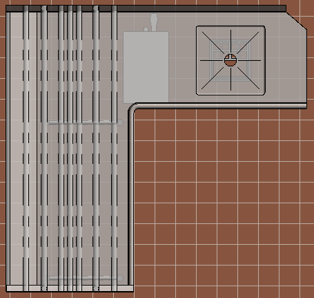
Alright well that is a bit expected. I inserted this family into a new project template that doesn't have any subcategories created yet so I didn't expect it to look any different. The checkered pattern behind the table is the tile floor. As you can see, this table is not transparent. If it was transparent then we would be able to see the tile floor underneath the table. That is an issue that we are going to solve very shortly.
Here is the same view but with a shaded view.

Let's take a look at the subcategory settings.

On the Manage tab, click on the Object Styles button.

Scroll down to the Specialty Equipment section and click on the + sign to expand and see the subcategories. Remember this was an empty project template so I didn't create any subcategories in it. All of the subcategories that you see above under Specialty Equipment were created when I inserted the dishtable family. That is why our dishtable doesn't look any different in our project or in our family, they look the same because they are using the same subcategory settings.
But what if I already set the subcategories in the project file before I inserted the family.
To simulate this I am going to remove the dishtable family, set the subcategories, then re-insert the same dishtable family. If you were following along you would notice that when you remove a family from a project, the subcategories are not removed with it.

Above are the new subcategory settings I went with. I got rid of the magenta because I only use color for clearances but that is just my preference. For the Line Patterns, I actually used some patterns that I created on my own that are optimized for 1/4" scale.

And here is our dishtable once we inserted it back into our project. Remember we didn't change any of the subcategories in the dishtable family, we only changed the subcategories in our project file. And since those subcategory names matched exactly, all of the object styles from our project file override the object styles in the family file.
This shows that as long as the person making the family sets the subcategories, the designer can control exactly how the family will look when it's inserted into their project.
Customization and automation all in one, can't beat it. So we figured it out, set the subcategories and everything is gravy, what's so hard about that? Well a lot actually...

Take a look at this list of subcategories. This isn't even all of them, there is another 100 that I couldn't fit on the screen. This is my old project template from when I was an active foodservice designer. The reason we had all of these subcategories was not because we added them, these are all of the subcategories that were in the families we had used over the years. So we kept them and set their object styles just like the others to be ready for the next time a family with a subcategory in this list gets inserted into our project.
Could we have fixed the subcategories in the families instead? Sure, but editing every family that we used is the exact problem that we are trying to avoid.
We did try to fix them too, as you can see above we also set some of the incorrect categories to Magenta which helped us see the incorrect subcategories when we inserted them into a project.
To be honest, this massive list is better than not having a subcategory at all. I mean it's not like we had to actively manage this list. This list is just every subcategory in every family we inserted which we then added to our template. It populated itself when families with incorrect subcategories were inserted. It's is a much bigger problem when a family doesn't have any of it's elements set to subcategories, then we have no control whatsoever.
That is why it is so important for content creators and everybody else that creates families to use subcategories. They give the designer control over the look of their plans.
And what names should content creators use when they create the subcategories? Well I already went over a few but here is a more complete list:
- QF_2DOutline_Overcounter - Used for symbolic lines that identify the above counter height equipment boundaries
- QF_2DOutline_Undercounter - Used for symbolic lines that identify the below counter height equipment boundaries
- QF_2DOutline - Used for symbolic lines that identify the counter height equipment boundaries
- QF_3DGeometry_Overcounter - Used for geometry above counter height
- QF_3DGeometry_Undercounter - Used for geometry below counter height
- QF_3DGeometry - Used for geometry at counter height
- QF_Details_Surface - Used for model lines on the surface of geometry
- QF_Details_Cutout - Used for symbolic lines that identify the cutout dimensions for a drop-in piece of equipment
- QF_Clearances_Code - Used for symbolic lines that identify a code mandatory clearance around the equipment
- QF_Clearances_Door_Drawer - Used for symbolic lines that identify the opening path of a door swing or open drawer
- QF_Clearances_Service - Used for symbolic lines that identify a factory service clearance around the equipment
- QF_Logo - Used for all elements that are used to create a manufacturer logo
- QF_Electrical - Used for all elements that should only be visible on the electrical plan
- QF_Plumbing - Used for all elements that should only be visible on the plumbing plan
- QF_Mechanical - Used for all elements that should only be visible on the mechanical plan
- QF_SpecialConditions - Used for all elements that should only be visible on the special conditions plan
Does this mean that no more subcategories can be added? Not at all. I mean look at that massive list above, more subcategories doesn't cause more problems, but if you are going to create new subcategories it would be best if you use the same naming convention and tell the industry what you are using. And it would nice for the industry as a whole to talk about standard subcategories, to debate this list, and to add more subcategories so the content creators don't have to make them up on the fly.
Because at the end of the day, all content creators want is to know what subcategories they should be using and all designers want is to know what subcategories they need to be prepared for.
Alright before we jump into transparency, let's take a quick detour to learn about graphic display styles since they have a role to play here to, albeit a minor one.
The Five Graphic Display Styles in Revit
Revit has five different graphic display styles that can be changed seamlessly: Wireframe, Hidden Line, Consistent Colors, Shaded, and Realistic. The most commonly used style for architectural design is Hidden Line by a mile.

Wireframe (above) may seem helpful but you end up seeing straight through the building.

Hidden Line (above) is the standard display style used by almost all designers. Black-and-white floor plans made in Revit were almost certainly made with the Hidden Line display style.

Consistent Colors (above) is similar to Shaded but without the shadows and gradient. It's a bit cartoonish and if you are already going for color, why not just use Shaded?

Shaded (above) is the best looking color display style in Revit. It uses a default light source to add shading and gradient while also displaying the colors of the materials that are set.

Realistic (above) is like a quick rendering, it never turns out as good as you think it should. It is also always too dark because foodservice designers don't typically design light sources which Revit uses when rendering the display type.

Graphic Display Options are great, they allow designers to quickly switch any view to any style. They can be used to quickly change a view to wireframe which helps when selecting undercounter items. They can be used to quickly change to a color view so you can see how different materials are turning out. Switching between black-and-white and color in Revit is super simple and seamless. It is also possible to do both and I think that is the real takeaway here, why not use both?
But most designers don't use both, most of them only use the Hidden Line style and may only use Shaded or color in general for their of 3D views.
Color floor plans have not caught on yet but I expect that will change in the future and we should always be ready for the future.
Unlike subcategories, graphic display styles don't have anything to do with line colors or line patterns. As you can see from the images above, our dishtable still has the same line colors and line patterns in every view. Although display styles may seem like they can be used to control transparency, they are really only good for controlling whether your views are color or not.
There is one more special property of subcategories that you probably haven't noticed and that I haven't mentioned since the beginning. Invisibility.

Well really the ability to be hidden in the form of checkboxes that can be used to hide all the elements in the subcategory. These checkboxes are located in the project's Visibility/Graphics Overrides which is on the View tab.
Subcategories can have their visibility turned off so they can be used to hide elements in any view.
Up to this point we haven't actually seen the finished results of this differents methods of customization. The family that we created has separate subcategories for our 2D outline and for our 3D geometry but we haven't discussed how they should be used. Why did we need to set multiple subcategories for 2D outlines and 3D geometry? When should one be visible and when should one be hidden? What is the purpose of having line patterns for 3D geometry? To answer these questions I first must explain the two ways that foodservice designers make equipment transparent.
Transparency
Foodservice designer have a special need that most other designers don't, the need to be able to see through a piece of equipment to see what's underneath. Undershelves, trash cans, crossbracing, undercounter refrigeration, and of course floor sinks. Foodservice design is layered, it doesn't just happen at the countertop level. Instead of designing at one level, foodservice design happens at three heights, undercounter, counter height , and overcounter. It is for this reason that we must be able to see through our equipment. And that is why transparency is so important. Let me show you.
Why Foodservice Designers Need Equipment Families to be Transparent

In the above image we have our dishtable family and we have two other families. One is a floor sink and the other is a booster heater. Here is a 3D color image too.

Both of these families need to be located underneath the dishtable. So let's see what happens when I place them where they need to go.

You probably expected that. If you have great eyes you might be able to see a nice piece of the floor sink through the sink drain, but otherwise it's all hidden. It's not hard to see that this is a problem.

Equipment being located underneath other equipment is a big part of foodservice design, we usually have very little space to work with so squeezing equipment into empty spaces is necessary.
That is why we need to make equipment transparent, otherwise pieces of equipment may not be seen by stakeholders and plumbing rough-ins might be missed by the construction team. So how do we fix this?
How to Make Equipment Transparent in Revit
At the current time there are two main methods that foodservice designers use to make control their visibility and graphics and make equipment transparent.
One method uses 2D outlines and turns the 3D geometry off, the other method removes the 2D outlines, shows the 3D geometry in plan view and uses transparency.
If symbolic lines weren't already serving another purpose then I would say that the 2D outline method should not be used but symbolic lines do serve a purpose as we already learned.
When symbolic lines are used for 2D outlines, 3D geometry must be turned off otherwise you won't see the outlines. Revit offers a way of turn 3D geometry off in plan views inside a family using a Visibility/Graphics Override. That method is currently in wide use but should be abandoned and subcategories should be used instead. The method involves disabling the geometry in the Family Element Visibility/Graphics Override which is a family override.

The problem with this method of hiding 3D geometry is that it can't be controlled by the designer from inside the project. Once a family is inserted, the settings inside the family are forced upon the designer.
That means every designer that likes to use 3D geometry in plan views has to edit every family that has been overridden and turn the 3D geometry back on.
That is why we need the 2D elements and the 3D elements on different subcategories, so that the designer can control visibility from inside the project.

With subcategories all we need to do is turn off the QF_3DGeometry subcategories in the project's Visibility/Graphics Overrides to hide the geometry. Visibility/Graphics Overrides can be applied on a per view basis so you can change these settings depending on the type of view.

A byproduct of turning the 3D geometry off is transparency. Remember transparency is just the ability to see through the equipment and when no 3D geometry is visible you can see right through the equipment which is technically 100% transparency.
So you could say that the 2D outline method is a two for one, not only do we get the perfect amount of detail from 2D outlines, we also get transparency which is a necessity.
This also has led some to believe that symbolic 2D outlines are only used for transparency which isn't correct, symbolic 2D outlines do give us transparency but the the reason they are required is for controlling how families look in floor plan views.
The second method is the 3D geometry method. In this method the designer shows the 3D geometry, hides or removes the 2D outlines, and uses Revit's transparency. There is no other way to control which lines are visible, but there are other ways to control transparency. Transparency can also be relative, it doesn't have to be 100% or 0%. Hiding geometry is really just 100% transparent geometry, but what if you wanted to make the equipment 50% transparent?
Revit's internal transparency property can be used to override a single element in a view, to create a filter that controls a group of elements, or as a category override for all specialty equipment families.
Revit does have its own way of handling transparency. It works great and can be customized in a number of different ways including any transparency from 0% to 100%. Everybody should understand it because it can be very helpful in a pinch, even if you are using the symbolic line method.
You could create a filter that uses a project parameter to control transparency, every time you want a family to be transparent all you would need to do is click a checkbox. Not enough? Then how about overriding the transparency property for the Specialty Equipment category to make all specialty equipment families transparent. Those options are all wide-ranging, but if you wanted to be precise than you could change the transparency of a single family in a single view using just a right click.
Transparency is not difficult to control in Revit. The difficult part is more likely to be choosing which method to use. We got time though so let's just go through all of them.
First up, our Transparency Override project parameter filter.

First thing to do is go to the Manage tab and click on the Project Parameter button.

Next click Add...

We will name our new project parameter Transparency Override. Make sure you set it to Instance so we can control a single family at a time. Make it a Yes/No parameter to give us a checkbox. I like to group this under Graphics, seems fitting. Finally make sure you set the category to Specialty Equipment. This will add our new parameter to every Specialty Equipment family in the project. If you are using other categories besides Specialty Equipment and you want to override their transparency also then you will need to include them here as well. Click OK to create the parameter.

Once you return to the project, select any Specialty Equipment family. In the Properties Palette you will see your new Transparency Override parameter. You will notice that the checkbox is grayed out. This means it's value hasn't been set yet, so technically this is not a Yes or a No, it's more like a null. Clicking this parameter right now won't do anything, we have to set up our filter first.

Let's do that now, on the View tab click on the Filters button.

We don't have any filters yet so this list is empty. Let's create one now by clicking on the New Filter button.

First we need to name our filter, I am going to go with Transparency Override Filter.

Next we need to create our filter. First select the family categories we want to use the filter on which is Specialty Equipment. Then use the Filter By dropdown to select the parameter we just created which was Transparency Override. Then we need to add the condition which for this will be Equals Yes. Remember the checkbox will default to null so this condition means our filter will only be activated if we click it on.
Click OK to return to the project.
Now you are probably thinking that we are done, but there is one more important step. So far we have created a project parameter to be used by our filter and we have created a filter, but we still haven't defined what the filter will do. We know when the filter will be active, but we haven't set what will happen when it is active. To do this we need to go to Visibility/Graphic Overrides.

On the View tab, click on the Visibility/Graphics button.
Visibility Graphics Overrides is where categories and subcategories are controlled and it is also where Filters are applied.

First we must add our Filter to this view. Click on the Add button.

Select the filter we created and click OK.

Ok we added the filter to our view and we have just one final step of specifying the Transparency Override. Click on the Override button under Transparency.

As I mentioned earlier, we don't have to choose between 0 and 100 but for this exercise I will use 100% transparency. Finally click OK here and again on the V/G Overrides screen to return to the project.

And there you go. Just select any Specialty Equipment family and click the Transparency Override checkbox to automatically make a family transparent.
Filters are a great tool that can also be used to override line patterns or surface patterns. You could create a parameter called Existing and create a filter that automatically sets the line pattern to Dashed.
Next up for Transparency tutorials, let's go over how to override the transparency for a family category like Specialty Equipment.

For this we only need to go back to Visibility/Graphics.

Scroll down to the Specialty Equipment category and click the Override button under Transparency.

And just like before we will set our Transparency to 100%. Then click OK twice and return to the project. Now it doesn't matter if the Transparency Checkbox is used or not, all Specialty Equipment families in this view will be 100% transparent.
If you wanted to, you could even alter the Filter override to set the transparency back to 0% when the checkbox is clicked. So instead of every family being solid except the ones with Transparency Override checked, every family could be transparent except for the ones with Transparency Override checked.
Ok now let me show you a more precise method that can be used on a single family.

This one is quick, all you need to do is right-click your family and click Override Graphics in View By Element...

The click the arrow next to Surface Transparency to display the slider and set it to 100%. Once you click you will return to the project and your family will be transparent. This works great if you are in a rush and don't have time to correct the underlying issue. This also only overrides the family in a single view.
You may be wondering what happens if you use all three of these transparency methods. Which method takes precedence and overrides the others? Here is a nice graphic to help you understand the hierarchy of Visibility and Graphics Overrides.

So if we had all three methods for transparency, the Override Graphics by Element would take precedence. Followed by the Filter, then the Visibility/Graphics Overrides. Then of course last is the Object Styles which are really the settings that are being overridden.
Alright transparency experts, now lets go over how to use 3D geometry in plan views using your new transparency skills.
Subcategories + Transparency
Earlier we discussed a method of using 2D symbolic outlines and turning the 3D geometry off to achieve transparency and control which lines are shown in plan views. That method certainly has its advantages but now we are going to go over a different method.
The 3D geometry method doesn't use 2D outlines at all, instead the 3D geometry is turned on in plan views and the details of the equipment are similar to a top down 3D view.
Instead of hiding the 3D geometry to create transparency, we will leave the 3D geometry on and use Revit's internal transparency properties. The result is something new, something with depth, and something that looks really great in color.
Alright so here is our dishtable family with 2D outlines and 3D geometry visible.

Now let's turn off the 2D outlines using our subcategories.

And here is what it looks like now with only 3D geometry visible.

The only difference is the cross bracing underneath, before you could see the 2D outlines of the crossbracing. Now that we turned those 2D outlines off you are unable to see the crossbracing because it is hidden by the top. We know how to fix this so let's make it transparent, but instead of making it 100% transparent let's only make it 50% transparent.

The result is something that you can only get with 3D geometry and 50% transparency. You can now see the undercounter equipment, the crossbracing, and the floor sink. But if you look closely, all of these elements that are under the 3D geometry are different than everything else.

Instead of just showing up as more black lines, they show up as gray lines.
Revit uses grayscale to indicate the level of transparency when using 3D geometry and transparency for hidden elements, this is special to the 3D geometry method.
With a bit of tweaking you can get the grayscale to show up as a lighter line which to the human eye naturally translates as being farther away, or in this case being obstructed by something else.

Drop the transparency to 15% and switch to a color shaded view for a great looking color floor plan with just enough transparency to see the undercounter equipment when you look closely.

Or don't use transparency at all and create a top down view of your foodservice design in color and 3D. This view could be used as your cover page to get the viewer excited about your design. Transparency is important but isn't required for every single view in your set.
When you have the ability to control 2D and 3D separately, you have the ability to create anything you want.
I have been saying that it is impossible to control which lines are visible when using 3D geometry in plan views but that wasn't quite correct. There is one trick but it can't be used everywhere.
Controlling How 3D Geometry Looks in Plan Views by Joining Geometry
Earlier when we discussed why symbolic lines are important I showed you how Revit automatically added a line for a radius edge. You can see it again on this image we just looked at.

I didn't get into it before but there is actually a way to get rid of this extra line in the 3D geometry. All you have to do is Join the two pieces of geometry together. Now I say that, but keep in mind that to Join geometry in Revit, both pieces of geometry must line up perfectly. it also means that both pieces of geometry must have the same material, subcategory, and visibility parameter. So while it is possible, it isn't always possible.

Here is a closeup of the dishtable where the radius edge meets the countertop. This edge is the extra line that we are seeing in the floor plan view. Let's join these elements together.

Go to the Modify tab and click on the Join button.
Now all you we need to do is select the two elements that we want to join together. Remember TAB is your friends when selecting elements.

Once you join them together you will notice that the edge dissappears. Return to your floor plan view to find that it has disappeared.

And just like that, we have a 3D geometry family that looks just like a 2D outlined family. It's not hard to see why some designers prefer 2D and some designers prefer 3D.
Joining geometry that belongs together is a best practice and all content creators should be taking advantage of this feature so foodservice designers have better looking families to work with.
Line Patterns
You probably saw why we had to set line patterns for the 3D geometry. When 3D geometry is transparent, the line patterns of the hidden elements will be visible and grayscale (unless 100% transparent).
Line patterns in Revit are easy to customize and make your own. Let me show you really quick because they can be tricky to find. Line patterns are located in Additional Settings on the Manage tab.

Line Patterns are located in Additional Settings on the Manage tab.

Click Additional Settings and then click Line Patterns.
Line patterns are simple to make, they can only contain 3 different parts. Dashes, Dots, and Spaces. Dashes and Spaces both are defined by length. Dots don't have a length. I find that the best way to learn how to make line patterns is just by looking at existing line patterns.

Here is the Undercounter line pattern that I used. The default Revit Dash line pattern uses a 1/8" Dash and a 1/8" Space. I wanted my dashes to be a bit shorter and I wanted them closer together so as you can see from above I changed the Dash length to 1/16" and the Space length to 1/32".

Here is the Overcounter line pattern I also used. As you can see this one is a bit more complicated because it is a more complex pattern. We first start out with a Dash, then a Space, then a short Dash, then another Space, then another short Dash, then a Space before the pattern starts to repeat itself. Line patterns are a great way to distinguish undercounter elements from overcounter elements.
Remember that line patterns will look different when you change the scale of the view, but also remember that you can create different line patterns for different scales and use V/G Overrides to set them.
Whenever a family is inserted into a project, all of its line patterns will be transferred to the project file. If there are line patterns of the same name already in the project file, then the project's line patterns will override the line patterns in the family. Line patterns are similar to subcategories in this way and that's a great thing.
Detail Level
Alright I know you must be ready for this to end but there is just one more topic that we must include since it is the last piece of this puzzle. Detail Level is a family setting per element meaning it must be set in the family for each element. It is very similar to the way we turned off 3D geometry in plan views and that is actually the same window where Detail Level is set.

There are three detail levels, Coarse, Medium, and Fine. These are basically just buckets that you can place different elements into to be controlled later. When you insert the family into a Project, you can set the Detail Level of the View.

If you set your view to Medium, all elements that were set to Coarse or Medium will be displayed and all elements set to Fine will be hidden. Detail level is a helpful feature for foodservice designers to use when elements are categorized correctly. For the most part, foodservice designers use the Medium level for their equipment plan and the Coarse level for their MEP plans.
Setting the perimeter of the equipment to the Coarse level and setting all other details to the Medium setting would be all that is necessary from the family creator.
Using the Fine setting may result in an element that is never seen by a designer and thus should not be used exclusively.
But detail level is another family setting that can't be controlled from the project so if foodservice designers need to correct a detail level issue then they will need to edit the family. Whereas if the elements were on their own subcategory then they could just be controlled on a per view basis from the project's visibility and graphics settings.
Detail level and subcategories are mutually exclusive properties and both of them can and should be used together.
Summary
We have gone over just about every visibility and graphics Revit topic up to this point but it's time to bring it all together. The main purpose of this article was to show how foodservice designers can customize the look of their plans and how foodservice family creators can assist foodservice designers by creating families that can be customized in multiple different ways from the project environment. Some foodservice designers like families with 2D outlines while other foodservice designers prefer to show the 3D geometry in plan views. Why not build families in a way that makes them both happy? Why not build families in a way that lets foodservice designers get the look they want without having to edit a family? Using this method of 2D and 3D standardized subcategories, foodservice content creators can build families that all foodservice designers can customize any way they like.
Findings:
- Subcategories can give Revit family content creators the option of building a single family that satisfies all designers. The other option is to build two families, one for each type of designer, but all parties involved want to avoid that option.
- Foodservice designers prefer to control the Object Styles globally from the project instead of having to control them individually in every family.
- Subcategories are case-sensitive and if the names in your family and your project do not match exactly then your project's object styles will not override the family object styles.
- When you set subcategories for 3D geometry, the 3D geometry elements will display the Line Color, Line Pattern, Line Weight, and Material just like the 2D Revit elements.
- Model Lines are more like 3D geometry than 2D lines. In foodservice they are typically used to draw surface details that should be visible in 3D such as the crease lines in sinks or the perimeter of control panels.
- Symbolic lines are required is because 3D geometry in a floor plan view doesn't always look the way it should or look the way you want it to.
- We use symbolic lines to remove the extra lines that Revit adds when displaying 3D geometry in 2D plans.
- Our goal is to already have the subcategories in our project file for every subcategory that we may encounter in an equipment family. If we succeed, than whenever we insert a family into our project it will automatically look exactly the way we want it to.
- As long as the person making the families sets the subcategories for every element, then the designer can control exactly how the family will look when it's inserted into their project.
- Subcategories can be fixed in the families but editing every family is the exact problem that foodservice designers are trying to avoid.
- It is so important for content creators and everybody else that creates families to use subcategories to give the designer control over the look of their plans.
- Content creators do not need to set any of the object styles when using standard subcategories.
- Color floor plans have not caught on yet but that will change in the future and we should always be ready for the future when building standards.
- Subcategories can have their visibility turned off so they can be used to hide elements in any view.
- There are two methods that foodservice designers use for controlling their visibility and graphics, some use 2D outlines and turn 3D geometry off, others remove the 2D outlines, show 3D geometry in plan view and use transparency.
- The 2D outline method involves hiding all of the geometry in floor plan views while showing all of the symbolic lines that outline the equipment.
- The byproduct of transparency from the 2D outline method has led some to believe that symbolic 2D outlines are only used for transparency which isn't correct, symbolic 2D outlines do give us transparency but the the reason they are required is for controlling how families look in floor plan views.
- Revit's internal transparency property can be used to override a single element in a view, to create a filter that controls a group of elements, or as a category override for all specialty equipment families.
- Filters are a great tool that can also be used to override line patterns or surface patterns. You could create a parameter called Existing and create a filter that automatically sets the line pattern to Dashed.
- The 3D geometry method doesn't use 2D outlines at all, instead the 3D geometry is visible in plan views and the details of the equipment are similar to a top down 3D view.
- Revit uses grayscale to indicate the level of transparency when using 3D geometry and transparency for hidden elements, this is special to the 3D geometry method.
- When you have the ability to control 2D and 3D separately, you have the ability to create anything you want.
- Joining geometry that belongs together is a best practice and all content creators should be taking advantage of this feature so foodservice designers have better looking families to work with.
- Remember that line patterns will look different when you change the scale of the view, but also remember that you can create different line patterns for different scales and use V/G Overrides to set them.
- Setting the perimeter of the equipment to the Coarse level and setting all other details to the Medium setting would be all that is necessary from the family creator.
- Detail level and subcategories are mutually exclusive properties and both of them can and should be used together.
Standard List of Subcategories
- QF_2DOutline_Overcounter - Used for symbolic lines that identify the above counter height equipment boundaries
- QF_2DOutline_Undercounter - Used for symbolic lines that identify the below counter height equipment boundaries
- QF_2DOutline - Used for symbolic lines that identify the counter height equipment boundaries
- QF_3DGeometry_Overcounter - Used for geometry above counter height
- QF_3DGeometry_Undercounter - Used for geometry below counter height
- QF_3DGeometry - Used for geometry at counter height
- QF_Details_Surface - Used for model lines on the surface of geometry
- QF_Details_Cutout - Used for symbolic lines that identify the cutout dimensions for a drop-in piece of equipment
- QF_Clearances_Code - Used for symbolic lines that identify a code mandatory clearance around the equipment
- QF_Clearances_Door_Drawer - Used for symbolic lines that identify the opening path of a door swing or open drawer
- QF_Clearances_Service - Used for symbolic lines that identify a factory service clearance around the equipment
- QF_Logo - Used for all elements that are used to create a manufacturer logo
- QF_Electrical - Used for all elements that should only be visible on the electrical plan
- QF_Plumbing - Used for all elements that should only be visible on the plumbing plan
- QF_Mechanical - Used for all elements that should only be visible on the mechanical plan
- QF_SpecialConditions - Used for all elements that should only be visible on the special conditions plan
We help our clients present their ideas in the best light! info@cgistudio.com.ua
5moChristopher, 👍
Axis Designs
1yWow- great article.
Chargé de projets - Concepteur chez BPA. commençant le 2 avril prochain !
1yThanks to you ! Great Job ! It's easier for me to understand ! 👍
Food Service Revit Power User, LEED AP, CFSP, TRUE Advisor, retired. Passionate about Environmental Design
4yWhew, a master class in subcategories! A great read. Clip and save. Well done, Chris!
Mericle | Making NEPA a Preferred Destination for Commerce
4yGod bless you. I got a thumb cramp while scrolling through the comprehensive dissertation. Talk about EXPERTISE! Well done CH 👏👏👏