Samsung 740NW Service Manual
Hide thumbs
Also See for 740NW:
- Owner's manual (72 pages) ,
- Manual del usuario (76 pages) ,
- Manual (86 pages)
Table of Contents

Related Manuals for Samsung 740NW


Summary of Contents for Samsung 740NW
-
Page 1: Service Manual
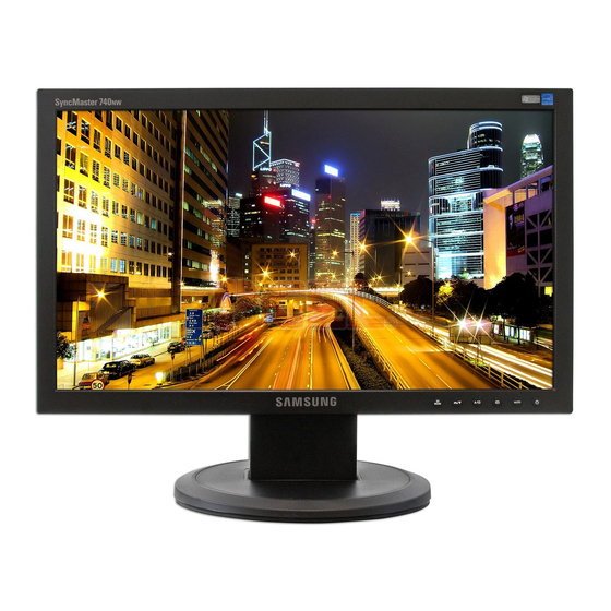
LCD-Monitor Chassis Model LS17HAN 740NW SERVICE Manual TFT-LCD Monitor Fashion Feature -Integrated UI applied -Built-in Scaler Sync Separator -Connectivity : Analog (15p Dsub), Analog Solution -Power Consumption : 20W -DPMS : under 1 W (230Vac) - Page 2 Copyright Trademarks Samsung is the registered trademark of Samsung ©2006 by Samsung Electronics Co., Ltd. Electronics Co., Ltd. All rights reserved. LS17HAN and MacMaster Cable Adapter are This manual may not, in whole or in part, be copied, trademarks of Samsung Electronics Co., Ltd.
-
Page 3: Table Of Contents
Contents . Precautions ………………………………………………………………………………………………………………………………………1 1-1 Safety Precautions ……………………………………………………………………………………………………………………… 1-1 1-2 Servicing Precautions …………………………………………………………………………………………………………………… 1-2 1-3 Electrostatically Sensitive Devices (ESD) Precautions ……………………………………………………………………………… 1-2 1-4 Installation Precautions ………………………………………………………………………………………………………………… 1-3 . Product specifications …………………………………………………………………………………………………………………………2 2-1 Fashion Feature…………………………………………………………………………………………………………………………… 2-1 2-2 Specifications ……………………………………………………………………………………………………………………………… 2-1 2-3 Spec Comparison ………………………………………………………………………………………………………………………… 2-2 2-4 Option Specification ………………………………………………………………………………………………………………………... - Page 4 Contents . Wiring Diagram …………………………………………………………………………………………………………………………………8 9. S chematic Diagrams ……………………………………………………………………………………………………………………………9 9-1 Schematic Diagrams …………………………………………………………………………………………………………………… 10-1 9-2 IP BOARD (POWER) …………………………………………………………………………………………………………………… 10-2 9-3 IP BOARD (INVERTER) ……………………………………………………………………………………………………………… 10-3 0. Operating Instructions and Installation … … …………………………………………………………………………………………………10-1 10-1 Front …………………………………………………………………………………………………………………………………… 10-1 10-2 Rear……………………………………………………………………………………………………………………………………… 10-2 10-3 Connecting the monitor ………………………………………………………………………………………………………………...
- Page 5 Samsung Electronics Co.,Ltd. -This Service Manual is a property of Samsung 416, Maetan-3Dong, Yeongtong-Gu, Suwon City, Electronics Co., Ltd. Gyeonggi-Do, Korea, 443-742 Any unauthorized use of Manual can be punished Printed in Korea under applicable International and/or domestic P/N : BN82-00171C-00 law.
-
Page 6: Precautions
1 Precautions 1 Precautions Follow these safety, servicing and ESD precautions to prevent damage and to protect against potential hazards such as electrical shock. 1-1 Safety Precautions 1-1-1 Warnings For continued safety, do not attempt to modify the circuit board. Disconnect the AC power and DC power jack before servicing. -
Page 7: Servicing Precautions
1 Precautions 1-2 Servicing Precautions WARNING: An electrolytic capacitor installed with the wrong polarity might explode. Caution: Before servicing units covered by this service manual, read and follow the Safety Precautions section of this manual. Note: If unforeseen circumstances create conflict between the following servicing precautions and any of the safety precautions, always follow the safety precautions. -
Page 8: Installation Precautions
1 Precautions 1-4 Installation Precautions 1. For safety reasons, more than two people are 6. Keep the antenna far away from any high-voltage required for carrying the product. cables and install it firmly. Contact with the highvoltage cable or the antenna falling over may 2. - Page 9 1 Precautions Memo...
-
Page 10: Product Specifications
2 Product Specifications 2 Product Specifications 2-1 Fashion Feature - Integrated UI applied - Analog Solution - Built-in Scaler Sync Separator - Connectivity : Analog (15p Dsub), - Power Consumption : 20W - DPMS : under 1 W (230Vac) - Power: Internal Power with Inverter (5V - 2A, 13V - 2A) - 100 ~ 240 Voltage, SEMCO 2-2 Specifications Item Description... -
Page 11: Spec Comparison
2 Product Specifications 2-3 Spec Comparison LME19BS LS17HAN Model Design Frequency Horizontal 30 ~ 81 kHz 30~61 kHz Vertical 60 ~ 75 Hz 56~75 Hz Display Color 16,2M colors 16,2M colors PC Resolution 1280 x 1024 / 60 Hz 1280 x 720 / 60 Hz Maximum mode Input Signal Sync Signal... -
Page 12: Option Specification
2 Product Specifications 2-4 Option Specification Item Item Name CODE.NO Remark Quick Setup Guide BH68-00376L Warranty Card (Not available in all BH68-70448A locations) User's Guide, Monitor Driver, BN59-00509Q Natural Color software, MagicTune™ software D-Sub(15 Pin) BN39-00244B Cable Power Cord 3903-000042... - Page 13 2 Product Specifications Memo...
-
Page 14: Alignments And Adjustments
3 Alignments and Adjustments 3 Alignments and Adjustments This section of the service manual explains how to use the DDC MANAGER JIG. This function is needed for AD board change and program memory (IC110) change. 3-1 Required Equipment The following equipment is necessary for adjusting the monitor: - Computer with Windows 95, Windows 98, or Windows NT. -
Page 15: Service Function Spec
3 Alignments and Adjustments 3-6 Service Function Spec. 3-6-1 How to Display Service Function OSD 1. The value for brightness and contrast should be changed to zero. 2. Within 5 seconds, press the (Enter/Source) key. 3. Service function OSD will be displayed. If you want to disable the service function OSD, you will have to power off. - Page 16 3 Alignments and Adjustments 3-6-3 How to Control Service Function OSD -After changing the panel or lamp, you must reset service function OSD. -The case of panel change After changing the panel, press the menu key within 5 seconds,. Then, panel Ch. No increases one step and the panel time information is reset to zero. Simultaneously, other information is reset to zero (Upper/Lower lamp, Panel cycle).
-
Page 17: How To Execute Ddc
1) Run DDC Manager MTI-2031. 2) Select a DDC file name. Progtam : WinDDC BY SAMSUNG ELEC.Co. [Ver:4.65.12V] --- Modify : 20050425 3) Insert into DDC Manager Port 1 (analog) and make the DDC input as for the old dual model. -
Page 18: How To Execute Mcu Code
3 Alignments and Adjustments 5. Type in the monitor serial number and press Enter. *Repeat this step 2 to 5 times the analog input. 3-8 How to execute MCU Code 3-8-1 Program Setting - Config Setting 1. Click Config Setting 2. - Page 19 3 Alignments and Adjustments 3-8-2 Change Batch File Path and DownLoad Code 4. Open the Batch file. 5. Change the Code's Path to saved Path at your PC. 6. Save the Batch file. 7. Write Batch command "batch batch file name.txt" 8.
-
Page 20: Troubleshooting
4 Troubleshooting 4 Troubleshooting Notes: 1. Before troubleshooting, setup the PC 's display as below. • Resolution: 1280 x 720 • H-frequency: 45 kHz • V-frequency: 60 Hz 2. If no picture appears, make sure the power cord is correctly connected. 3. - Page 21 4 Troubleshooting...
-
Page 22: No Video (Analog)
4 Troubleshooting 4-2 No Video Check the signal cable and its connections. Does X300 oscillate Check and replace the related correctly? circuits. Do the R, G, B inputs Check the input part. appear on R134, R135, and R138? Do the Hsync and Vsync Check IC300 and its related circuits. - Page 23 4 Troubleshooting...
- Page 24 4 Troubleshooting WAVEFORMS...
-
Page 25: Ip Board (Power)
4 Troubleshooting 4-3 IP BOARD (POWER) Power On Change FUSE Check fuse 3 pin of FDM0565R Check the Vcc system Vcc system in normal: HIGH 1 pin of FDM0565R Check the drain system Check the main switching Normal: Switching Check the Check the Check the output current protection system... -
Page 26: Ip Board (Inverter)
4 Troubleshooting 4-4 IP BOARD (INVERTER) Power On Check the 13V line Check the power system Check the IC drive 1 and 2 pins of FDM0565R Check MOSFET Check Protection Normal:0.6V~0.8V 1 and 2 pins of FDM0565R Check the OVP and OLR Check Protection circuits Normal:0.6V~0.8V... - Page 27 4 Troubleshooting Memo...
-
Page 28: Exploded View And Parts List
5 Exploded View & Parts List 5 Exploded View and Parts List -You can search for updated part codes through ITSELF web site. URL : http://itself. sec. samsung.co.kr 5-1 Exploded View M0013 M0006 M0215 M0014 T0003 M0174 M0003 M0013... -
Page 29: Parts List
5 Exploded View & Parts List 5-2 Parts List Location Code.No Item & Specification Q'ty SA/SNA Remark T0003 BN96-04589B ASSY COVER P-FRONT;LS17HAN (740NW),ABS H M0215 BN07-00352A LCD-PANEL;CLAA170WA02,Haydn,6bit FRC,393 M0174 BN44-00164A IP BOARD;IP-19145A,HAYDN,3.2 ~4.9mA,7.2 M0014 BN94-01160E ASSY PCB MAIN-PTZ,W/W;LS17HANSB/XSH S.N.A M0006 BN96-04591A ASSY SHIELD P-COVER;LS17HAN (740NW),SECC... -
Page 30: Electrical Parts List
Loc. No. Code No. Description & Specification Q'ty SA/SNA Remark LS17HANSS/EDC 740NW,WAA1/S17B2-LHA,17,LCD-MO,NETHERLAN M0001 BN90-01137A ASSY COVER FRONT;LS17HANSS/XSF,740NW S.N.A T0003 BN96-04589B ASSY COVER P-FRONT;LS17HAN (740NW),ABS H ...3 M0112 BN63-03023B COVER-FRONT;LS17HAN(740NW),ABS,T2.5,HB,S S.N.A ...3 T0022 BN64-00377B KNOB CONTROL;HA17TS,PC CLEAR,T2.1,9,112, S.N.A ...3 M0020 BN96-02474B ASSY BOARD P;HAYDN,YWP-HAYDN,17 FUNCTION... - Page 31 6 Electrical Parts List Level Loc. No. Code No. Description & Specification Q'ty SA/SNA Remark M0014 BN94-01160E ASSY PCB MAIN-PTZ,W/W;LS17HANSB/XSH S.N.A ...3 T0245 0202-001492 SOLDER-WIRE FLUX;HSE-02 LFM48 SR-34 S,-, 0.003 S.N.A ...3 CN101 3701-001219 CONNECTOR-DSUB;15P,3R,FEMALE,ANGLE,AUF ...3 BN97-01320E ASSY SMD-PTZ;LS17HANSB/XSH S.N.A ..4 SUB05 0202-001477...
- Page 32 6 Electrical Parts List Level Loc. No. Code No. Description & Specification Q'ty SA/SNA Remark ..4 R331 2007-000083 R-CHIP;3Kohm,5%,1/10W,TP,1608 ..4 R300 2007-000084 R-CHIP;4.7Kohm,5%,1/10W,TP,1608 ..4 R307 2007-000084 R-CHIP;4.7Kohm,5%,1/10W,TP,1608 ..4 R318 2007-000084 R-CHIP;4.7Kohm,5%,1/10W,TP,1608 ..4 R319 2007-000084 R-CHIP;4.7Kohm,5%,1/10W,TP,1608 ..4 R320 2007-000084 R-CHIP;4.7Kohm,5%,1/10W,TP,1608 ..4 R334 2007-000084 R-CHIP;4.7Kohm,5%,1/10W,TP,1608...
- Page 33 6 Electrical Parts List Level Loc. No. Code No. Description & Specification Q'ty SA/SNA Remark ..4 C610 2203-005005 C-CER,CHIP;100nF,10%,16V,X7R,1608 ..4 C611 2203-005005 C-CER,CHIP;100nF,10%,16V,X7R,1608 ..4 C615 2203-005005 C-CER,CHIP;100nF,10%,16V,X7R,1608 ..4 C616 2203-005005 C-CER,CHIP;100nF,10%,16V,X7R,1608 ..4 C617 2203-005005 C-CER,CHIP;100nF,10%,16V,X7R,1608 ..4 C618 2203-005005 C-CER,CHIP;100nF,10%,16V,X7R,1608 ..4 C619 2203-005005 C-CER,CHIP;100nF,10%,16V,X7R,1608...
- Page 34 6 Electrical Parts List Level Loc. No. Code No. Description & Specification Q'ty SA/SNA Remark ...3 T0562 6046-001013 STAND OFF;M3,L5,Ni PLT,SUM24L,#4-40 S.N.A M0006 BN96-04591A ASSY SHIELD P-COVER;LS17HAN (740NW),SECC S.N.A ...3 BN61-02429D STUD-PEM;PNB,M2.8,D7,L20,ZPC(SIL),SUM24L S.N.A ...3 M0001 BN63-01774A SHIELD-INSULATOR;BI17/19BS,PET,T0.35 S.N.A ...3 M0107 BN63-03025A SHIELD-COVER;LS17HAW,SECC,T0.8...
- Page 35 6 Electrical Parts List Memo...
-
Page 36: Block Diagram
7 Block Diagrams 7 Block Diagram 7-1 Power Tree... -
Page 37: Main Board Part
7 Block Diagrams 7-2 Main Board Part... -
Page 38: Ip Board Part (Smps Part)
7 Block Diagrams 7-3 IP Board Part (SMPS Part) -
Page 39: Ip Board Part (Inverter Part)
7 Block Diagrams 7-4 IP Board Part (Inverter Part) -
Page 40: Wiring Diagram
8 Wiring Diagram 8 Wiring Diagram CN601... - Page 41 8 Wiring Diagram Memo...
-
Page 42: S S Chematic Diagrams
9 Schematic Diagrams 9 Schematic Diagrams - This Document can not be used without Samsung s authorization. 9-1 Schematic Diagrams... -
Page 43: Ip Board (Power)
9 Schematic Diagrams 9-2 IP BOARD (POWER) -
Page 44: Ip Board (Inverter)
9 Schematic Diagrams 9-3 IP BOARD (INVERTER) - Page 45 9 Schematic Diagrams Memo...
-
Page 46: Operating Instructions And Installation
10 Operating Instructions and Installation 10 Operating Instructions and Installation 10-1 Front 1. Menu button 2) Text Opens the OSD menu. Also use to exit the OSD For documentations or works involving heavy text. menu or return to the previous menu. 3) Internet 2. -
Page 47: Rear
10 Operating Instructions and Installation 2,3. Adjust buttons 6. Power button Adjust items in the menu. Use this button for turn the monitor on and off. 4. Enter button 7. Power indicator Activates a highlighted menu item. This light glows green during normal operation, and blinks green once as the monitor saves your 5. -
Page 48: Connecting The Monitor
10 Operating Instructions and Installation 10-3 Connecting the monitor Rear of Computer Rear of Monitor New Model macintosh 1. Connect the power cord for your monitor to the power port on the back of the monitor. Plug the power cord for the monitor into a nearby outlet. 2-1. -
Page 49: Attaching A Base
10 Operating Instructions and Installation 10-4 Attaching a Base - This monitor accepts a 75mm x 75mm VESA-compliant mounting interface pad. A. Monitor B. Mounting interface pad (Sold separately) 1. Turn off your monitor and unplug its power cord. 2. Lay the LCD monitor face-down on a flat surface with a cushion beneath it to protect the screen. 3. -
Page 50: Disassembly And Reassembly
11 Disassembly and Reassembly 11 Disassembly and Reassembly This section of the service manual describes the disassembly and reassembly procedures for the LS17HAN TFT-LCD monitors. WARNING: This monitor contains electrostatically sensitive devices. Use caution when handling these components. 11-1 Disassembly Cautions: 1. - Page 51 11 Disassembly and Reassembly 설 설 명 사 사 진 설명 Description Picture Description 3. Turn the monitor so that its front part is looking downwards. Then remove the back cover, as shown in the figure on the left. 4. Remove the lamp protection shield on the left of the shield (back cover).
- Page 52 11 Disassembly and Reassembly 설 설 명 사 사 진 설명 Description Picture Description 6. Remove 2 screws. 7. Turn the shield so that its inside looks upwards. Remove all the screws on the main board and the IP board (total 4 screws). Then remove the protection shield at the bottom of the IP board.
-
Page 53: Reassembly
11 Disassembly and Reassembly 11-2 Reassembly Reassembly procedures are in the reverse order of disassembly procedures. 11-4... -
Page 54: Pcb Diagram
12 PCB Layout 12 PCB Diagram 12-1 Main PCB LVDS POWER CONNECTOR egulator 3.3 SCALER UNCTION lash Memory Regulator EEPROM - NVRAM EPROM - Analog 12-1... - Page 55 12 PCB Layout Memo 12-2...
-
Page 56: Circuit Descriptions
13 Circuit Descriptions 13 Circuit Descriptions 13-1 Overall Block Structure Power Tree 13-1-1 1. When the AD board is in DPMS state: 1.1 The IP has been designed so that it operates with a power consumption of less than 0.6W of. 1.2 The Scaler consumes power up to 37mA 1.3 The power to the panel is switched off 2. - Page 57 13 Circuit Descriptions Main Board Parts 13-1-2 1. Inverter: A conversion device that converts DC 6. SCALER & EEPROM: I2C is a two-way serial rated voltage/current to high ones necessary bus of two lines that supports communications for the panel lamp. across the integrated circuits as well as between FLASH and EEPROM.
- Page 58 13 Circuit Descriptions 13-1-3 IP BOARD BLOCK(POWER) Parts 13-1-4 IP BOARD BLOCK(INVERTER ) Parts 13-3...
- Page 59 13 Circuit Descriptions 13-1-5 IP BOARD ( inverter ) PROTECTION Parts BIZET INVERTER CONTROLER FAN7310 have 2-way of the PROTECTION MODE. 1. OVP[Over Voltage Protection] : If the Voltage of the series capacitors C10 & C15 is over the 2.0V, the Inverter latched-off.[See the Picture1] 2.
-
Page 60: Reference Infomation
14 Reference Infomation 14 Reference Infomation 14-1 Technical Terms -TFT-LCD -FINE The "Fine" adjustment is used to adjust visibility by (Thin film Transistor Liquid Crystal Display) ADC(Analog to Digital Converter) controlling phase difference. This is a circuit that converts from analog signal to digital signals. - Page 61 14 Reference Infomation user. The frequency of this repetition per second is called Vertical Frequency or Refresh Rate. Unit: Hz Example: If the same light repeats itself 60 times per second, this is regarded as 60 Hz. -Horizontal Frequency The time to scan one line connecting the right edge to the left edge of the screen horizontally is called Horizontal Cycle.
-
Page 62: Pin Assignments
14 Reference Infomation 14-2 Pin Assignments Sync 15-Pin D-Sub Signal Cable Connector Type Separate Composite Sync-on-green Pin No. Green Green Green + H/V Sync. Blue Blue Blue DDC Return (GND) DDC Return (GND) DDC Return (GND) GND-R GND-R GND-R GND-G GND-G GND-G GND-B... -
Page 63: Timing Chart
14 Reference Infomation 14-3 Timing Chart This section of the service manual describes the timing that the computer industry recognizes as standard for computer- generated video signals. Table 14-1 Timing Chart VESA Mode VGA2/ VGA3/ 640/75 Hz 800/60 Hz 800/75 Hz 1024/60 Hz 1024/75 Hz 1280/60 Hz... -
Page 64: Preset Timing Modes
14 Reference Infomation 14-4 Preset Timing Modes -If the signal transferred from the computer is the same as the following Preset Timing Modes, the screen will be adjusted automatically. However, if the signal differs, the screen may go blank while the power LED is on. -
Page 65: Panel Description
14 Reference Infomation 14-5 Panel Description Maker VENDOR P/N PANEL_CODE PANEL_ABB STICKER_CODE Remarks LT140X1-002 BN07-00004A BN68-00239H LT150XS-L01 BN07-00009A LT150XS-L01-B BN07-00022A LTM150XS-L02 BN07-00005A LT181E2-132 BN07-00001A LT150XS-T01 BN07-00010A LTM181E3-132 BN07-00019A LT170E2-131 BN07-10001D LT181E2-131 BN07-10001E LTM170E4-L01 BN07-00018A LTM240W1-L01 BN07-00015A LTM213U3-L01 BN07-00016A LTM150XH-L01 BN07-00026A LTM150XH-L03 BN07-00027A LTM150XS-L01... - Page 66 14 Reference Infomation Maker VENDOR P/N PANEL_CODE PANEL_ABB STICKER_CODE Remarks LTA320W1-L01 BN07-00108A Panel for AMLCD 32" TV LTM213U4-L01 BN07-00124A NARROW BEZEL 21 " PANEL LTM170E6-L04 BN07-00129A HIGHLAND 17" LOW PANEL (Panel only for TCO03) LTM190E1-L01 BN07-00088A LTM190E1-L01 ZPD panel M150X4-L06 BN07-00137A 15"...
- Page 67 14 Reference Infomation Maker VENDOR P/N PANEL_CODE PANEL_ABB STICKER_CODE Remarks LTM201UX-L01 BN07-00249A AMLCD 20.1" TN NEW Panel Code LTM240M1-L02-A05 BN07-00250A 24" High brightness Slim panel ZPD code derivation LTA320W3-L02 BN07-00219A AMLCD 32" NEW FFL Panel LTA320W2-L11 BN07-00259A IP Board for AMLCD 32" 16:9 NEW Panel LTA460WS-L02 BN07-00252A AMLCD 46"...
- Page 68 14 Reference Infomation Maker VENDOR P/N PANEL_CODE PANEL_ABB STICKER_CODE Remarks HANNSTAR HSD150MX41A(A) BN07-00020A TTL type HANNSTAR HSD150MX12 BN07-00030A TTL type HANNSTAR HSD170ME13 BN07-00180A Hannstar 17" TN new panel development HANNSTAR HSD170ME13 BN07-00180B Hannstar 17" TN new panel development ZPD code deriva- tion HANNSTAR HSD190ME12...
- Page 69 14 Reference Infomation Maker VENDOR P/N PANEL_CODE PANEL_ABB STICKER_CODE Remarks HYUNDAI HT15X15-D00 BN07-00146A Development for Ares 15" Hydis TV HYUNDAI HT15X15-D01 BN07-00146B Derivation panel HPD for Ares 15" Hydis TV HYUNDAI HT17E13-100 BN07-00167A PINEHURST-2(IBM) PJT 17" HYDIS PANEL Derivation HYUNDAI HT17E13-100 BN07-00167B PINEHURST-2(IBM) Hydis 17"...
- Page 70 14 Reference Infomation Maker VENDOR P/N PANEL_CODE PANEL_ABB STICKER_CODE Remarks CHIMEI M170E6-L05 BN07-00152A CMO 17" new panel development code CHIMEI M170E6-L05 BN07-00152B CMO 17" ZPD panel code derivation CHIMEI M150X4-L06 BN07-00137B Chimei 15" Narrow & Slim panel ZPD derivation CHIMEI M170E5-L05 BN07-00165A CMO 17"...
- Page 71 14 Reference Infomation Memo 14-12...